Juniper MX240 Hardware Manual
5g universal routing platform
Hide thumbs
Also See for MX240:
- Hardware manual (512 pages) ,
- Instruction for upgrading (35 pages) ,
- Quick start manual (31 pages)

Related Manuals for Juniper MX240


Summary of Contents for Juniper MX240
- Page 1 MX240 5G Universal Routing Platform Hardware Guide Modified: 2019-07-01 Copyright © 2019, Juniper Networks, Inc.
- Page 2 END USER LICENSE AGREEMENT The Juniper Networks product that is the subject of this technical documentation consists of (or is intended for use with) Juniper Networks software. Use of such software is subject to the terms and conditions of the End User License Agreement (“EULA”) posted at https://support.juniper.net/support/eula/.
-
Page 3: Table Of Contents
MX240 Craft Interface Overview ........35... - Page 4 MX240 DC Power Supply LEDs ........
- Page 5 MX240 PIC Description ........
- Page 6 Installing an MX240 Router Overview ........165...
- Page 7 Lift ........... 194 Connecting the MX240 Router to Power ....... . 195 Tools and Parts Required for MX240 Router Grounding and Power Connections .
- Page 8 Powering Off the MX240 Router ........206...
- Page 9 Removing an MX240 MPC ........284...
- Page 10 Power On the MX240 Router ........341...
- Page 11 MX240 PIC Serial Number Label ........369...
- Page 12 AC Power Disconnection Warning ........398 MX240 DC Power Electrical Safety Guidelines ......399 DC Power Copper Conductors Warning .
- Page 13 Figure 32: DPC Installed Horizontally in the MX240 Router ....94 Figure 33: MX240 DPC Interface Port Mapping ......96 Figure 34: Typical FPCs Supported on the MX240 Router .
- Page 14 MX240 5G Universal Routing Platform Hardware Guide Figure 39: MPC Installed Horizontally in the MX240 Router ....128 Figure 40: Application Services Modular Line Card (AS MLC) ....134 Figure 41: Application Services Modular Processing Card (AS MXC) .
- Page 15 Figure 95: Removing a Routing Engine from an MX960 Router ....245 Figure 96: Installing a Routing Engine in an MX240 Router ....246 Figure 97: Installing a Routing Engine in an MX480 Router .
- Page 16 Figure 142: Serial Number ID Label ........363 Figure 143: MX240 Chassis Serial Number Label ......363 Figure 144: SCB Serial Number Label .
- Page 17 Table 3: MX240 Router Capacity ........
- Page 18 Table 78: Rack Requirements and Specifications for an MX240 Router ..145 Table 79: MX240 Common Component Power Requirements ....148 Table 80: FRU Power Requirements .
- Page 19 List of Tables Table 81: Sample Power Requirements for an MX240 Router ....157 Table 82: Calculating Power Budget ........158 Table 83: Calculating Input Power Examples .
- Page 20 MX240 5G Universal Routing Platform Hardware Guide Copyright © 2019, Juniper Networks, Inc.
-
Page 21: About The Documentation
® To obtain the most current version of all Juniper Networks technical documentation, see the product documentation page on the Juniper Networks website at https://www.juniper.net/documentation/ If the information in the latest release notes differs from the information in the documentation, follow the product Release Notes. -
Page 22: Merging A Full Example
MX240 5G Universal Routing Platform Hardware Guide Merging a Full Example To merge a full example, follow these steps: From the HTML or PDF version of the manual, copy a configuration example into a text file, save the file with a name, and copy the file to a directory on your routing platform. -
Page 23: Documentation Conventions
Alerts you to the risk of personal injury from a laser. Indicates helpful information. Best practice Alerts you to a recommended use or implementation. Table 2 on page xxiv defines the text and syntax conventions used in this guide. Copyright © 2019, Juniper Networks, Inc. xxiii... -
Page 24: Table 2: Text And Syntax Conventions
MX240 5G Universal Routing Platform Hardware Guide Table 2: Text and Syntax Conventions Convention Description Examples Bold text like this Represents text that you type. To enter configuration mode, type the configure command: user@host> configure Fixed-width text like this Represents output that appears on the user@host>... -
Page 25: Documentation Feedback
Requesting Technical Support Technical product support is available through the Juniper Networks Technical Assistance Center (JTAC). If you are a customer with an active Juniper Care or Partner Support Services support contract, or are covered under warranty, and need post-sales technical support, you can access our tools and resources online or open a case with JTAC. -
Page 26: Self-Help Online Tools And Resources
MX240 5G Universal Routing Platform Hardware Guide Self-Help Online Tools and Resources For quick and easy problem resolution, Juniper Networks has designed an online self-service portal called the Customer Support Center (CSC) that provides you with the following features: Find CSC offerings: https://www.juniper.net/customers/support/... -
Page 27: Overview
MX240 System Overview The MX240 router is an Ethernet-optimized edge router that provides both switching and carrier-class Ethernet routing. The MX240 enables a wide range of business and residential applications and services, including high-speed transport and VPN services, next-generation broadband multiplay services, high-speed Internet and data center internetworking. -
Page 28: Mx240 Hardware Overview
MX240 Hardware Overview The MX240 router is five rack units (U) tall. Several routers can be stacked in a single floor-to-ceiling rack, for increased port density per unit of floor space. Fully populated, the MX240 provides a maximum aggregate switch fabric capacity of up to 1.92 Tbps and line-rate throughput for up to 48 10-Gigabit Ethernet ports, or four... -
Page 29: Table 4: Switch Control Board Capacities For Mx Series 5G Universal Routing Platforms (Full-Duplex)
Several types of line cards, are available. For a list of the supported line cards, see the MX Series Interface Module Reference Four SCBs are available for the MX240 routers—SCB-MX, the SCBE-MX, SCBE2-MX, and SCBE3-MX. Table 4 on page 29 compares the fabric bandwidth capacities of SCBs per MX-series router. -
Page 30: Mx240 Chassis
MX240 Component Redundancy on page 34 MX240 Craft Interface Overview on page 35 MX240 Alarm Relay Contacts on the Craft Interface on page 35 MX240 Alarm LEDs and Alarm Cutoff/Lamp Test Button on page 36 MX240 Component LEDs on the Craft Interface on page 36... -
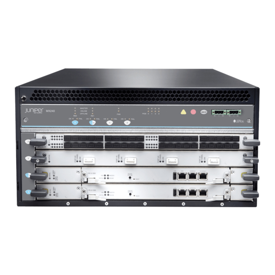
Page 31: Figure 1: Front View Of A Fully Configuredmx240 Router
P E M 0 P E M 1 A IR F ILT E R P E M 2 P E M 3 FA N T R AY Air filter ESD point Fan tray Air exhaust Copyright © 2019, Juniper Networks, Inc. -
Page 32: Figure 3: Rear View Of A Fully Configured Ac-Powered Mx240 Router
MX240 5G Universal Routing Platform Hardware Guide Figure 3: Rear View of a Fully Configured AC-Powered MX240 Router (220 V) Figure 4: Rear View of a Fully Configured DC-PoweredMX240 Router Protective earthing DC Power supplies Power supply exhaust P E M 0... -
Page 33: Mx240 Router Hardware And Cli Terminology Mapping
MX240 Router Physical Specifications on page 142 MX240 Router Hardware and CLI Terminology Mapping The MX240 router supports the components in Table 5 on page Table 5: MX240 Router Hardware Components and CLI Terminology Component Hardware Model Number CLI Name... -
Page 34: Mx240 Component Redundancy
To operate, each host subsystem requires a Routing Engine installed directly into in an SCB. In the high-line (220 V) AC power configuration, the MX240 router contains one or two AC power supplies, located horizontally at the rear of the chassis in slots... -
Page 35: Mx240 Craft Interface Overview
One power supply can provide the maximum configuration with full power for as long as the router is operational. In the low-line (110 V) AC power configuration, the MX240 router contains either two AC power supplies (nonredundant), located horizontally at the rear of the chassis in... -
Page 36: Mx240 Alarm Leds And Alarm Cutoff/Lamp Test Button
Host Subsystem LEDs on the MX240 Craft Interface on page 37 Power Supply LEDs on the MX240 Craft Interface on page 37 DPC and MPC LEDs on the MX240 Craft Interface on page 37 FPC LEDs on the MX240 Craft Interface on page 38... -
Page 37: Host Subsystem Leds On The Mx240 Craft Interface
Chapter 1: Overview SCB LEDs on the MX240 Craft Interface on page 38 Fan LED on the MX240 Craft Interface on page 39 Host Subsystem LEDs on the MX240 Craft Interface Each host subsystem has three LEDs, located in the middle of the craft interface, that indicate its status. -
Page 38: Fpc Leds On The Mx240 Craft Interface
MX240 5G Universal Routing Platform Hardware Guide Table 9: DPC and MPC LEDs on the Craft Interface Label Color State Description Green On steadily Card is functioning normally. Blinking Card is transitioning online or offline. – The slot is not online. -
Page 39: Fan Led On The Mx240 Craft Interface
Chapter 1: Overview Fan LED on the MX240 Craft Interface The fan LEDs are located on the top left of the craft interface. Table 12 on page 39 describes the functions of the fan LEDs. Table 12: Fan LEDs on the Craft Interface... -
Page 40: Mx240 Fan Led
Figure 9: Fan Tray Figure 10: Air Filter See Also Troubleshooting the MX240 Cooling System on page 350 MX240 Fan LED Each fan has an LED that displays its status. The fan LEDs are located on the top left of the craft interface. -
Page 41: Mx240 Ac Power System
The router cannot be powered from AC and DC power supplies simultaneously. The MX240 router is configurable with two, three, or four AC power supplies or one or two DC power supplies. The power supplies connect to the midplane, which distributes the different output voltages produced by the power supplies to the router components, depending on their voltage requirements. -
Page 42: Mx240 Ac Power Supply Description
MX240 5G Universal Routing Platform Hardware Guide Troubleshooting the MX240 Power System on page 356 MX240 AC Power Supply Description Each AC power supply weighs approximately 5.0 lb (2.3 kg) and consists of one AC appliance inlet, one AC input switch, a fan, and LEDs to monitor the status of the power supply. -
Page 43: Ac Power Supply Configurations
In the high-line (220 V) AC power configuration, the MX240 router contains one or two AC power supplies, located horizontally at the rear of the chassis in slots PEM0 (left to right). -
Page 44: Ac Power Supply Electrical Specifications For The Mx240 Router
LEDs for more information. AC OK DC OK See Also Connecting Power to an AC-Powered MX240 Router with Normal-Capacity Power Supplies on page 197 MX240 Chassis Grounding Specifications on page 53 AC Power Supply Electrical Specifications for the MX240 Router Table 14 on page 44 lists the AC power supply electrical specifications;... -
Page 45: Ac Power Circuit Breaker Requirements For The Mx240 Router
Replacing an MX240 AC Power Supply Cord on page 314 MX240 AC Power Electrical Safety Guidelines and Warnings AC Power Circuit Breaker Requirements for the MX240 Router on page 45 AC Power Circuit Breaker Requirements for the MX240 Router We recommend that you use a dedicated customer site circuit breaker rated for 15 A (250 VAC) minimum for each AC power feed, or as required by local code. -
Page 46: Ac Power Cord Specifications For The Mx240 Router
MX240 5G Universal Routing Platform Hardware Guide AC Power Cord Specifications for the MX240 Router Each AC power supply has a single AC appliance inlet located on the power supply that requires a dedicated AC power feed. Most sites distribute power through a main conduit that leads to frame-mounted power distribution panels, one of which can be located at the top of the rack that houses the router. -
Page 47: Figure 13: Ac Plug Types
It has a separate protective earthing terminal (sized for UNC 1/4-20 ground lugs) provided on the chassis in addition to the grounding pin of the power supply cord. This separate protective earthing terminal must be permanently connected to earth. Copyright © 2019, Juniper Networks, Inc. -
Page 48: Errata With The Mx240 Router Documentation
MX240 DC Power Supply Description on page 48 MX240 DC Power Supply LEDs on page 50 DC Power Supply Electrical Specifications for the MX240 Router on page 51 DC Power Circuit Breaker Requirements for the MX240 Router on page 52... -
Page 49: Dc Power Supply Configurations
NOTE: Do not set the input mode switch if the power supply is installed in the chassis. If the power supply is already installed, you must remove it before setting the input mode switch. Copyright © 2019, Juniper Networks, Inc. -
Page 50: Mx240 Dc Power Supply Leds
Fan tray, DPC slots , and SCB slots PEM2 See Also Connecting Power to a DC-Powered MX240 Router with Normal-Capacity Power Supplies on page 199 MX240 Chassis Grounding Specifications on page 53 MX240 DC Power Supply LEDs Each DC power supply faceplate contains three LEDs that indicate the status of the... -
Page 51: Dc Power Supply Electrical Specifications For The Mx240 Router
Chapter 1: Overview See Also MX240 Component LEDs on the Craft Interface on page 36 Connecting Power to a DC-Powered MX240 Router with Normal-Capacity Power Supplies on page 199 MX240 Chassis Grounding Specifications on page 53 DC Power Supply Electrical Specifications for the MX240 Router Table 19 on page 51 lists the DC power supply electrical specifications. -
Page 52: Dc Power Circuit Breaker Requirements For The Mx240 Router
Connecting Power to a DC-Powered MX240 Router with Normal-Capacity Power Supplies on page 199 Installing an MX240 DC Normal Capacity Power Supply on page 317 Disconnecting an MX240 DC Power Supply Cable on page 320 Calculating Power Requirements for MX240 Routers on page 156 DC Power Circuit Breaker Requirements for the MX240 Router Each DC power supply has a single DC input (–48 VDC and return) that requires a... -
Page 53: Mx240 Chassis Grounding Specifications
Chapter 1: Overview MX240 Chassis Grounding Specifications MX240 Chassis Grounding Points Specifications on page 53 MX240 Router Grounding Cable Lug Specifications on page 54 MX240 Router Grounding Cable Specifications on page 54 MX240 Chassis Grounding Points Specifications To meet safety and electromagnetic interference (EMI) requirements and to ensure proper operation, the router must be adequately grounded before power is connected. -
Page 54: Mx240 Router Grounding Cable Lug Specifications
MX240 5G Universal Routing Platform Hardware Guide Figure 17: Connecting DC Power to the Router MX240 Router Grounding Cable Lug Specifications The accessory box shipped with the router includes one cable lug that attaches to the grounding cable (see Figure 18 on page 54) and two UNC 1/4–20 screws used to secure... -
Page 55: Dc Power Source Cabling For The Mx240 Router
Chapter 1: Overview See Also Tools and Parts Required for MX240 Router Grounding and Power Connections on page 195 Grounding the MX240 Router on page 196 Preventing Electrostatic Discharge Damage to an MX240 Router on page 380 DC Power Source Cabling for the MX240 Router Figure 19 on page 55 shows a typical DC source cabling arrangement. -
Page 56: Dc Power Cable Specifications For The Mx240 Router
Connecting Power to a DC-Powered MX240 Router with Normal-Capacity Power Supplies on page 199 Installing an MX240 DC Normal Capacity Power Supply on page 317 Connecting an MX240 DC Power Supply Cable on page 204 Calculating Power Requirements for MX240 Routers on page 156... -
Page 57: Outstanding Issues With The Mx240 Router
You need to insert the optics and fiber firmly until the latch is securely in place. [PR/98055] Do not mix AC and DC power supplies on an MX240 router. Mixing of AC supplies and DC supplies may damage your chassis. [PR/233340]... -
Page 58: Mx240 Host Subsystem Description
Each host subsystem has three LEDs that display its status. The host subsystem LEDs are located in the middle of the craft interface. See Also MX240 Component LEDs on the Craft Interface on page 36 Maintaining the MX240 Host Subsystem on page 227 Taking an MX240 Host Subsystem Offline MX240 Host Subsystem LEDs Each host subsystem has three LEDs that display its status. -
Page 59: Mx240 Routing Engine Description
See Also MX240 System Overview on page 27 MX240 Chassis Description on page 30 MX240 Dense Port Concentrator (DPC) Description on page 93 MX240 SCB-MX Description MX240 Flexible PIC Concentrator (FPC) Description on page 101 MX240 Power System Description on page 41 MX240 Routing Engine Description The Routing Engine is an Intel-based PC platform that runs Junos OS. -
Page 60: Figure 22: Re-S-2000 Routing Engine
MX240 5G Universal Routing Platform Hardware Guide NOTE: If two Routing Engines are installed, they must both be the same hardware model. The RE-S-X6-64G-LT Routing Engine is equipped with limited encryption support only. Figure 22: RE-S-2000 Routing Engine Figure 23: RE-S-1800... -
Page 61: Re-S-X6-64G And Re-S-X6-64G-Lt Routing Engine Components
10— SSD card slot cover LEDs— RE-S-X6-64G and RE-S-X6-64G-LT Routing Engine Components In MX240 routers with dual Routing Engines, both the Routing Engines must be RE-S-X6-64G Routing Engines. Each RE-S-X6-64G Routing Engine (shown in Figure 24 on page 60) consists of the following components: CPU—Runs Junos OS to maintain the routing tables and routing protocols. -
Page 62: Routing Engine Interface Ports
MX240 5G Universal Routing Platform Hardware Guide NOTE: For specific information about Routing Engine components (for example, the amount of DRAM), issue the command. show vmhost hardware Routing Engine Interface Ports Three ports, located on the right side of the Routing Engine, connect the Routing Engine to one or more external devices on which system administrators can issue Junos OS command-line interface (CLI) commands to manage the router. -
Page 63: Re-S-1800 Routing Engine Description
See Also Removing an MX240 Routing Engine on page 230 Installing an MX240 Routing Engine on page 232 MX240 Routing Engine Serial Number Label on page 371 RE-S-1800 Routing Engine Description Figure 26 on page 63 shows RE-S-1800 routing engine. -
Page 64: Re-S-1800 Routing Engine Leds
MX240 5G Universal Routing Platform Hardware Guide CompactFlash card—Provides primary storage for software images, configuration files, and microcode. The CompactFlash card is fixed and is inaccessible from outside the router. Solid-state Drive (SSD)—Provides secondary storage for log files, memory dumps, and rebooting the system if the CompactFlash card fails. -
Page 65: Re-S-X6-64G Routing Engine Description
CPU—Runs Junos OS to maintain the routing tables and routing protocols. EEPROM—Stores the serial number of the Routing Engine. DRAM—Provides storage for the routing and forwarding tables and for other Routing Engine processes. Copyright © 2019, Juniper Networks, Inc. -
Page 66: Re-S-X6-64G Routing Engine Boot Sequence
MX240 5G Universal Routing Platform Hardware Guide One 10-Gigabit Ethernet interface between the Routing Engine and Switch Control Board. Two 50-GB slim solid-state drives— (primary) and (secondary)—Provide SSD1 SSD2 storage for software images, configuration files, microcode, log files, and memory dumps. -
Page 67: Re-S-X6-128G Routing Engine Description
Junos OS manually. The Junos OS supports USB versions 3.0, 2.0, and 1.1. Interface ports—The CONSOLE , and MGMT provide access to management devices. Each Routing Engine has one 10/100/1000-Mbps Ethernet port for connecting Copyright © 2019, Juniper Networks, Inc. -
Page 68: Re-S-X6-128G Routing Engine Leds
MX240 5G Universal Routing Platform Hardware Guide to a management network, and two asynchronous serial ports—one for connecting to a console and one for connecting to a modem or other auxiliary device. button—Reboots the Routing Engine when pressed. RESET ONLINE/OFFLINE button—Brings the Routing Engine online or takes it offline when... -
Page 69: Re-S-X6-128G Routing Engine Boot Sequence
Indicates activity on the hard disk drive. Green Blinking Routing Engine is transitioning online. ONLINE On steadily Routing Engine is functioning normally. FAIL On steadily Routing Engine has failed. See Also Replacing an MX240 Routing Engine on page 230 Copyright © 2019, Juniper Networks, Inc. -
Page 70: Re-S-1800 Routing Engine Leds
MX240 5G Universal Routing Platform Hardware Guide RE-S-1800 Routing Engine LEDs Each Routing Engine has four LEDs that indicate its status. The LEDs, labeled MASTER , and , are located directly on the faceplate of the Routing STORAGE ONLINE OK/FAIL Engine. -
Page 71: Routing Engine Specifications
Blue On steadily This Routing Engine is the Master Routing Engine. See Also MX240 Routing Engine Description on page 59 MX960 Routing Engine Description Routing Engine Specifications Table 26 on page 72 lists the current specifications for Routing Engines supported on M Series, MX Series, and T Series routers. -
Page 72: Table 26: Routing Engine Specifications
MX240 5G Universal Routing Platform Hardware Guide Table 26: Routing Engine Specifications First Junos Switch Connection Control Routing Engine Processor Memory to PFEs Disk Media Support Board RE-400-768 400-MHz 768 MB Fast 40 GB 1 GB – Celeron Ethernet hard disk... - Page 73 8 GB or Gigabit 32 GB 4 GB 10.4 – 16 GB Ethernet CompactFlash card RE-S-1800x2 1800-MHz 8 GB or Gigabit 32 GB 4 GB 10.4 SCB, SCBE, 16 GB Ethernet CompactFlash SCBE2, card SCBE3 Copyright © 2019, Juniper Networks, Inc.
- Page 74 MX240 5G Universal Routing Platform Hardware Guide Table 26: Routing Engine Specifications (continued) First Junos Switch Connection Control Routing Engine Processor Memory to PFEs Disk Media Support Board RE-S-1800x4 1800-MHz 8GB or Gigabit 32 GB 4 GB 10.4 SCB, SCBE,...
-
Page 75: Table 27: Hardware Specifications Of The Re-Mx-X6, Re-Mx-X8, Re-Ptx-X8, Rcbptx, Re-Qfx10002-60C, And Re-Ptx10002-60C Routing Engines
Table 27: Hardware Specifications of the RE-MX-X6, RE-MX-X8, RE-PTX-X8, RCBPTX, RE-QFX10002-60C, and RE-PTX10002-60C Routing Engines Model Number Supported on Device Specifications RE-S-X6-64G MX240, MX480, and 6-core Haswell CPU MX960 Wellsburg PCH-based Routing Engine with 64-GB DRAM and two 64-GB solid-state drives (SSDs) Copyright © 2019, Juniper Networks, Inc. -
Page 76: Table 28: End-Of-Life Routing Engine Specifications
MX240 5G Universal Routing Platform Hardware Guide Table 27: Hardware Specifications of the RE-MX-X6, RE-MX-X8, RE-PTX-X8, RCBPTX, RE-QFX10002-60C, and RE-PTX10002-60C Routing Engines (continued) Model Number Supported on Device Specifications REMX2K-X8-64G MX2020 and MX2010 8-core Haswell CPU Wellsburg PCH-based Routing Engine with 64-GB DRAM and two... - Page 77 On routers that accept two Routing Engines, you cannot mix Routing Engine types except for a brief period (one minute or so) during an upgrade or downgrade to two Routing Engines of the same type. See Also Supported Routing Engines by Router on page 78 Copyright © 2019, Juniper Networks, Inc.
-
Page 78: Supported Routing Engines By Router
MX240 5G Universal Routing Platform Hardware Guide Supported Routing Engines by Router The following tables list the Routing Engines that each router supports, the first supported release for the Routing Engine in the specified router, the management Ethernet interface, and the internal Ethernet interfaces for each Routing Engine. -
Page 79: M10I Routing Engines
Table 31: M40e Routing Engines First Supported Management Internal Ethernet Model Number Name in CLI Output Junos OS Release Ethernet Interface Interface RE-600-2048 (EOL details: fxp0 fxp1 RE-3.0 RE-3.0 TSB14373 (RE-600) fxp2 RE-A-1000-2048 RE-A-1000 fxp0 fxp1 fxp2 Copyright © 2019, Juniper Networks, Inc. -
Page 80: M120 Routing Engines
MX240 5G Universal Routing Platform Hardware Guide M120 Routing Engines Table 32 on page 80 lists the Routing Engines supported by the M120 router. Table 32: M120 Routing Engines First First Supported Supported Management Name in CLI 32-bit Junos OS... -
Page 81: Mx5, Mx10, Mx40, And Mx80 Routing Engine
64-bit Junos OS Ethernet Internal Ethernet Number Output Release Release Interface Interface RE-S-MX104 Routing Engine 13.2 – fxp0 fxp1 fxp2 MX240 Routing Engines Table 36 on page 82 lists the Routing Engines supported by MX240 routers. Copyright © 2019, Juniper Networks, Inc. -
Page 82: Mx480 Routing Engines
MX240 5G Universal Routing Platform Hardware Guide Table 36: MX240 Supported Routing Engines First Supported First Supported Management Name in CLI 32-bit Junos OS 64-bit Junos OS Ethernet Internal Ethernet Model Number Output Release Release Interface Interface RE-S-1300-2048 RE-S-1300 –... -
Page 83: Mx960 Routing Engines
RE-S-2X00x6 16.1R1 RE-S-X6-64G-LT RE-S-2X00x6 -LT – 17.2R1 fxp0 ixlv0, igb0 RE-S-X6-128G RE-S-2X00x6-128 – 18.1R1 fxp0 ixlv0, igb0 MX960 Routing Engines Table 38 on page 84 lists the Routing Engines supported by MX960 routers. Copyright © 2019, Juniper Networks, Inc. -
Page 84: Mx2008 Routing Engines
MX240 5G Universal Routing Platform Hardware Guide Table 38: MX960 Supported Routing Engines First First Supported Supported Management Internal Name in CLI 32-bit Junos 64-bit Junos Ethernet Ethernet Model Number Output OS Release OS Release Interface Interface RE-S-1300-2048 (EOL –... -
Page 85: Mx2010 Routing Engines
RE-S-2X00x8 16.1R2 ixlv1 16.2R1 REMX2K-X8-64G-LT 17.2R1 fxp0 ixlv0 RE-S-2X00x8 ixlv1 REMX2K-X8-128G 18.1R1 fxp0 ixlv0 RE-MX200X8-128G ixlv1 MX2020 Supported Routing Engines Table 41 on page 86 lists the Routing Engines supported by MX2020 routers. Copyright © 2019, Juniper Networks, Inc. -
Page 86: Mx10003 Routing Engines
MX240 5G Universal Routing Platform Hardware Guide Table 41: MX2020 Supported Routing Engines Management Internal Name in CLI First Supported 64-bit Junos Ethernet Ethernet Model Number Output OS Release Interface Interface RE-MX2000-1800X4 RE-S-1800x4 12.3R2 fxp0 REMX2K-1800-32G-S 12.3R4 fxp0 RE-S-1800x4 13.2R1 REMX2K-X8-64G 15.1F5-S1... -
Page 87: Ptx1000 Routing Engines
RE-DUO-2600 ixgbe1 RCB-PTX-X6-32G 16.1R4 ixlv0 RE-PTX-2X00x6 17.1R1 ixlv1 This Routing Engine does not support Junos OS Release 16.2. PTX5000 Routing Engines Table 46 on page 88 lists the Routing Engines supported on the PTX5000. Copyright © 2019, Juniper Networks, Inc. -
Page 88: Ptx10008 And Ptx10016 Routing Engines
MX240 5G Universal Routing Platform Hardware Guide NOTE: PTX5000 supports 64-bit Junos OS only. The PTX5000 router supports two midplanes. The midplane identified as in the CLI output is supported in Junos OS releases, 12.1X48, Midplane-8S 12.3, and 13.2. The enhanced midplane, identified as Midplane-8SeP supported from Junos OS release 14.1 onwards. -
Page 89: T320 Routing Engines
Output Junos OS Release Junos OS Release Interface Interface RE-600-2048 (EOL – fxp0 fxp1 RE-3.0 TSB14373 details: RE-3.0 fxp2 (RE-600) RE-1600-2048 (EOL RE-4.0 – fxp0 fxp1 TSB14374 details: fxp2 RE-A-2000-4096 – fxp0 RE-A-2000 bcm0 Copyright © 2019, Juniper Networks, Inc. -
Page 90: T1600 Routing Engines
MX240 5G Universal Routing Platform Hardware Guide Table 49: T640 Routing Engines (continued) Management Internal Name in CLI First Supported 32-bit First Supported 64-bit Ethernet Ethernet Model Number Output Junos OS Release Junos OS Release Interface Interface RE-DUO-C1800-8G RE-DUO-1800 32-bit Junos OS on a... -
Page 91: T4000 Routing Engines
T4000 router in a routing matrix: 13.1 The T4000 router supports the CB-LCC control board. TX Matrix Routing Engines Table 52 on page 92 lists the Routing Engines supported by the TX Matrix router. Copyright © 2019, Juniper Networks, Inc. -
Page 92: Tx Matrix Plus Routing Engines
MX240 5G Universal Routing Platform Hardware Guide Table 52: TX Matrix Routing Engines First First Supported Supported Management Internal Name in CLI 32-bit Junos 64-bit Junos Ethernet Ethernet Model Number Output OS Release OS Release Interface Interface RE-600-2048 (EOL –... -
Page 93: Mx240 Line Card Components And Descriptions
MX240 DPC Port and Interface Numbering on page 95 MX240 Dense Port Concentrator (DPC) LEDs on page 98 DPCs Supported on MX240, MX480, and MX960 Routers on page 98 MX240 Dense Port Concentrator (DPC) Description A Dense Port Concentrator (DPC) is optimized for Ethernet density and supports up to... -
Page 94: Figure 31: Typical Dpcs Supported On The Mx240 Router
If a slot is not occupied by a DPC or an SCB, a blank panel must be installed to shield the empty slot and to allow cooling air to circulate properly through the router. Figure 31 on page 94 shows typical DPCs supported on the MX240 router. For more information about DPCs, see the MX Series Interface Module Reference... -
Page 95: Mx240 Dpc Port And Interface Numbering
Ethernet interface so—SONET/SDH interface xe—10-Gigabit Ethernet interface For a complete list of media types, see Interface Naming Overview. fpc—Slot in which the DPC is installed. On the MX240 router, the DPCs are represented in the CLI as through FPC 0 FPC 2 pic—Logical PIC on the DPC. -
Page 96: Figure 33: Mx240 Dpc Interface Port Mapping
MX Series Interface Module Reference port—Port number. The MX240 router supports up to three DPCs that install horizontally and are numbered from bottom to top. Figure 33 on page 96 shows a 40-port Gigabit Ethernet DPC with SFP installed in slot on the MX240 router. - Page 97 Interface Admin Link Proto Local Remote ge-2/0/0 ge-2/0/1 down ge-2/0/2 ge-2/0/3 ge-2/0/4 ge-2/0/5 ge-2/0/6 ge-2/0/7 ge-2/0/8 ge-2/0/9 ge-2/1/0 down ge-2/1/1 down ge-2/1/2 down ge-2/1/3 down ge-2/1/4 ge-2/1/5 ge-2/1/6 ge-2/1/7 ge-2/1/8 ge-2/1/9 down ge-2/2/0 down Copyright © 2019, Juniper Networks, Inc.
-
Page 98: Mx240 Dense Port Concentrator (Dpc) Leds
These DPCs have all been announced as End of Life (EOL). The End of Support (EOS) milestone dates for each model are published at https://www.juniper.net/support/eol/mseries_hw.html Table 55 on page 99 lists the DPCs supported by the MX240, MX480, and MX960 routers. Copyright © 2019, Juniper Networks, Inc. -
Page 99: Table 55: Dpcs Supported In Mx240, Mx480, And Mx960 Routers
Chapter 1: Overview Table 55: DPCs Supported in MX240, MX480, and MX960 Routers Maximum DPC Model Throughput First Junos DPC Name Number Ports per DPC OS Release Gigabit Ethernet Gigabit Ethernet DPC with SFP DPC-R-40GE-SFP 40 Gbps EOL (see PSN-2009-06-400... - Page 100 MX240 5G Universal Routing Platform Hardware Guide Table 55: DPCs Supported in MX240, MX480, and MX960 Routers (continued) Maximum DPC Model Throughput First Junos DPC Name Number Ports per DPC OS Release 10-Gigabit Ethernet Enhanced Ethernet Services DPC with DPCE-X-4XGE-XFP...
-
Page 101: Interface Modules-Fpcs And Pics
MX240 Flexible PIC Concentrator (FPC) Description on page 101 MX240 Flexible PIC Concentrator (FPC) LEDs on page 103 FPCs Supported by MX240, MX480, and MX960 Routers on page 104 MX240 PIC Description on page 104 MX240 PIC Port and Interface Numbering on page 105... -
Page 102: Figure 34: Typical Fpcs Supported On The Mx240 Router
MX240 5G Universal Routing Platform Hardware Guide Figure 34: Typical FPCs Supported on the MX240 Router MX-FPC2 FPC3 If a slot is not occupied by a DPC, an FPC, or an SCB, a blank panel must be installed to shield the empty slot and to allow cooling air to circulate properly through the router. -
Page 103: Mx240 Flexible Pic Concentrator (Fpc) Leds
Chapter 1: Overview Figure 35: FPC Installed in the MX240 Router Chassis SC B SC B FPC Components Each FPC consists of the following components: FPC card carrier, which includes two PIC slots. Up to two Packet Forwarding Engines, each consisting of one I-chip for Layer 3 processing and one Layer 2 network processor. -
Page 104: Fpcs Supported By Mx240, Mx480, And Mx960 Routers
Troubleshooting the MX240 FPCs on page 352 FPCs Supported by MX240, MX480, and MX960 Routers An FPC occupies two slots when installed in an MX240, MX480, or MX960 router. The maximum number of supported FPCs varies per router: MX960 router—6 FPCs MX480 router—3 FPCs... -
Page 105: Mx240 Pic Port And Interface Numbering
Ethernet interface For a complete list of media types, see Interface Naming Overview. fpc—Lowest slot number in which the FPC is installed. On the MX240 router, the FPC occupies two line card slots and is represented in the CLI as... -
Page 106: Mx240 Pic Leds
See Also MX240 Router Hardware and CLI Terminology Mapping on page 33 MX240 PIC LEDs Each PIC has LEDs located on the faceplate. For more information about LEDs on the PIC faceplate, see the “LEDs” section for each PIC in the... -
Page 107: Pics Supported By Mx240, Mx480, And Mx960 Routers
Chapter 1: Overview See Also PICs Supported by MX240, MX480, and MX960 Routers on page 107 MX240 PIC Description on page 104 Replacing an MX240 PIC on page 289 Maintaining MX240 PICs on page 288 PICs Supported by MX240, MX480, and MX960 Routers Table 57 on page 107 lists the PICs supported by MX240, MX480, and MX960 routers. -
Page 108: Interface Modules-Mpcs And Mics
MIC/MPC Compatibility The following tables provide a compatibility matrix for the MICs currently supported by MPC1, MPC2, MPC3, MPC6, MPC8, and MPC9 on MX240, MX480, MX960, MX2008, MX2010, MX2020, and MX10003 routers. Each table lists the first Junos OS release in which the MPC supports the MIC. - Page 109 11.4 11.4 MIC-3D-8CHOC3-4CHOC12 MIC-4COC3-2COC12-G, MIC-8COC3-4COC12-G (Channelized SONET/SDH OC3/STM1 (Multi-Rate) MICs with SFP) MIC-3D-16CHE1-T1-CE 13.2 13.2 12.3 12.3 (Channelized E1/T1 NOTE: Support for NOTE: Support for Circuit Emulation MIC) Non-Channelized MIC Non-Channelized MIC only. only. Copyright © 2019, Juniper Networks, Inc.
-
Page 110: Table 59: Mic/Mpc2 Compatibility
MX240 5G Universal Routing Platform Hardware Guide Table 58: MIC/MPC1 Compatibility (continued) MIC Name MPC1 MPC1E MPC1 Q MPC1E Q MIC-3D-8DS3-E3, 11.4 11.4 11.4 11.4 MIC-3D-8CHDS3-E3-B (DS3/E3 MIC) NOTE: You cannot run Channelized DS3 (MIC-3D-8CHDS3-E3) on non-Q MPCs. Channelized DS3 is supported only on Q and EQ-based MPCs. - Page 111 OC3/STM1 (Multi-Rate) MICs with SFP) MIC-3D-16CHE1-T1-CE 13.2 15.1 with 12.3 12.3 12.3 12.3 — 14.1R4, flexible 14.2R3 (Channelized E1/T1 Circuit NOTE: Support queuing with Junos Emulation MIC) for Non- option Continuity Channelized MIC only. 15.1 Copyright © 2019, Juniper Networks, Inc.
-
Page 112: Table 60: Mic/Mpc3 Compatibility
MX240 5G Universal Routing Platform Hardware Guide Table 59: MIC/MPC2 Compatibility (continued) MPC2E MPC2 MPC2E MPC2 MPC2E MPC2E MPC2E MIC Name MPC2 MPC2E NG Q MIC-3D-8DS3-E3, 11.4 11.4 14.1R4, 11.4 11.4 11.4 11.4 12.2 14.1R4, MIC-3D-8CHDS3-E3-B 14.2R3 14.2R3 with Junos... -
Page 113: Mic-3D-4Xge-Xfp
(SONET/SDH OC192/STM64 MIC with XFP) 15.1 15.1 MIC-3D-4COC3-1COC12-CE — — 14.1R4, 14.2R3 with Junos Continuity (Channelized OC3/STM1 (Multi-Rate) Circuit Emulation MIC with SFP) 15.1 MIC-3D-16CHE1-T1-CE — 15.1 with flexible queuing 15.1 option (Channelized E1/T1 Circuit Emulation MIC) Copyright © 2019, Juniper Networks, Inc. -
Page 114: Table 61: Mic/Mpc6 Compatibility
MX240 5G Universal Routing Platform Hardware Guide Table 60: MIC/MPC3 Compatibility (continued) MIC Name MPC3E MPC3E NG MPC3E NG Q MS-MIC-16G 13.2R2 14.1R4, 14.2R3 with Junos 14.1R4, 14.2R3 with Junos Continuity Continuity (Multiservices MIC) 15.1 15.1 NOTE: On MPC3E, the installation of the... -
Page 115: Table 62: Mic/Mpc8 Compatibility
MPC10003 JNP-MIC1 17.3 Multi-Rate Ethernet MIC JNP-MIC1-MACSEC 17.3R2 Multi-Rate Ethernet MIC See Also MICs Supported by MX Series Routers on page 116 Junos Continuity Software User Guide (Junos OS Release 14.1R4 and Later Releases) Copyright © 2019, Juniper Networks, Inc. -
Page 116: Mx240 Modular Interface Card (Mic) Description
The following tables list the first supported Junos OS release for the MX Series. Table 65 on page 116 lists the first supported Junos OS release for MICs on MX240, MX480, MX960, and MX2008 routers. Table 66 on page 119 lists the first supported Junos OS release for MICs on MX2010 and MX2020 routers. -
Page 117: Mic-3D-16Che1-T1-Ce
Chapter 1: Overview Table 65: MICs Supported by MX240, MX480, MX960 and MX2008 Routers (continued) MX240, MX480, and MX960 MIC Name MIC Model Number Ports Routers MX2008 Routers DS3/E3 MIC MIC-3D-8DS3-E3, 11.4 15.1F7 MIC-3D-8CHDS3-E3-B Circuit Emulation Channelized E1/T1 Circuit MIC-3D-16CHE1-T1-CE 12.3... - Page 118 MX240 5G Universal Routing Platform Hardware Guide Table 65: MICs Supported by MX240, MX480, MX960 and MX2008 Routers (continued) MX240, MX480, and MX960 MIC Name MIC Model Number Ports Routers MX2008 Routers 100-Gigabit Ethernet MIC with MIC6-100G-CFP2 15.1F7 CFP2 100-Gigabit DWDM OTN...
-
Page 119: Table 66: Mics Supported By Mx2010 And Mx2020 Routers
40-Gigabit Ethernet MIC with MIC3-3D-2X40GE-QSFPP 12.3 12.3 QSFP+ 100-Gigabit Ethernet 100-Gigabit Ethernet MIC with MIC3-3D-1X100GE-CFP 12.3 12.3 100-Gigabit Ethernet MIC with MIC3-3D-1X100GE-CXP 12.3 12.3 100-Gigabit Ethernet MIC with MIC6-100G-CXP 13.3R2 13.3R2 CXP (4 Ports) Copyright © 2019, Juniper Networks, Inc. - Page 120 MX240 5G Universal Routing Platform Hardware Guide Table 66: MICs Supported by MX2010 and MX2020 Routers (continued) MIC Name MIC Model Number Ports MX2010 Routers MX2020 Routers 100-Gigabit Ethernet MIC with MIC6-100G-CFP2 13.3R3 13.3R3 CFP2 100-Gigabit DWDM OTN 100-Gigabit DWDM OTN MIC MIC3-100G-DWDM 15.1F5...
-
Page 121: Table 67: Mics Supported By Mx5, Mx10, And Mx40 Routers
Channelized SONET/SDH MIC-3D-4CHOC3-2CHOC12 11.4 11.4 11.4 OC3/STM1 (Multi-Rate) MICs with SFP Channelized SONET/SDH MIC-3D-8CHOC3-4CHOC12 11.4 11.4 11.4 OC3/STM1 (Multi-Rate) MICs with SFP Channelized OC3/STM1 MIC-3D-4COC3-1COC12-CE 12.2 12.2 12.2 (Multi-Rate) Circuit Emulation MIC with SFP Copyright © 2019, Juniper Networks, Inc. -
Page 122: Table 68: Mics Supported By Mx80 And Mx104 Routers
MX240 5G Universal Routing Platform Hardware Guide Table 67: MICs Supported by MX5, MX10, and MX40 Routers (continued) MIC Name MIC Model Number Ports MX10 MX40 Channelized OC3/STM1 MIC-4COC3-1COC12-CE-H (Multi-Rate) Circuit Emulation MIC with SFP (H) Tri-Rate Tri-Rate MIC MIC-3D-40GE-TX –... - Page 123 MX80 and Junos fixed MX80-48T 13.3R3, 14.1R2, 14.2R1, MX104 supports only M u l t i s e r v i c e s MICs. SONET/SDH SONET/SDH OC192/STM64 MIC MIC-3D-1OC192-XFP 12.2 13.3 with XFP Copyright © 2019, Juniper Networks, Inc.
-
Page 124: Mx240 Modular Interface Card (Mic) Leds
Reference See Also MICs Supported by MX Series Routers on page 116 MX240 Modular Interface Card (MIC) Description on page 116 Maintaining MX240 MICs on page 279 Troubleshooting the MX240 MICs on page 354 Replacing an MX240 MIC on page 274 MX240 MIC Port and Interface Numbering Each port on a MIC corresponds to a unique interface name in the CLI. - Page 125 Chapter 1: Overview so—SONET/SDH interface xe—10-Gigabit Ethernet interface For a complete list of media types, see Interface Naming Overview. fpc—Slot in which the MPC is installed. On the MX240 router, the MPCs are represented in the CLI as through FPC 0 FPC 2 pic—Logical PIC on the MIC, numbered 0 or 1 when installed in slot 0, and 2 or 3 when...
-
Page 126: Figure 37: Mx240 Mic Interface Port Mapping
MX240 5G Universal Routing Platform Hardware Guide Figure 37: MX240 MIC Interface Port Mapping The MIC contains two logical PICs, numbered PIC 0 through PIC 1 in the CLI. Each logical PIC contains 10 ports numbered through command output displays a 20-port Gigabit Ethernet MIC show chassis hardware with SFP —... -
Page 127: Mx240 Modular Port Concentrator (Mpc) Description
MPCs interface with the power supplies and Switch Control Boards (SCBs). You must install redundant SCBs to support full line-rate. The MX240 router supports up to three MPCs. You must install a high-capacity fan tray to use an MPC. For power requirements, see “Calculating Power Requirements for MX240... -
Page 128: Figure 38: Typical Mpc Supported On The Mx240 Router
Figure 38 on page 128 shows a typical MPC supported on the MX240 router. Figure 39 on page 128 shows an MPC installed horizontally in the MX240 Router. For more information about MPCs, see the MX Series Interface Module Reference... -
Page 129: Mx240 Modular Port Concentrator (Mpc) Leds
Two LEDs, located on the craft interface above the MPC, display the status of the line cards and are labeled FAIL See Also MX240 Modular Port Concentrator (MPC) LEDs on page 129 MX240 Field-Replaceable Units (FRUs) on page 218 Replacing an MX240 MPC on page 284 MX240 Modular Port Concentrator (MPC) LEDs... -
Page 130: Mpcs Supported By Mx Series Routers
Table 70 on page 130 lists the MPCs and their first supported Junos OS release on MX240, MX480, MX960, MX2008, MX2010, MX2020, and MX10003 routers. Table 70: MPCs Supported by MX240, MX480, MX960, MX2008, MX2010, MX2020, and MX10003 Routers First Junos OS... - Page 131 Chapter 1: Overview Table 70: MPCs Supported by MX240, MX480, MX960, MX2008, MX2010, MX2020, and MX10003 Routers (continued) First Junos OS Release First First First First First MX240, Junos OS Junos OS Junos OS Junos OS Junos OS MX480, Release...
- Page 132 MX240 5G Universal Routing Platform Hardware Guide Table 70: MPCs Supported by MX240, MX480, MX960, MX2008, MX2010, MX2020, and MX10003 Routers (continued) First Junos OS Release First First First First First MX240, Junos OS Junos OS Junos OS Junos OS...
-
Page 133: Mx240 Application Services Modular Line Card Description
Chapter 1: Overview Table 70: MPCs Supported by MX240, MX480, MX960, MX2008, MX2010, MX2020, and MX10003 Routers (continued) First Junos OS Release First First First First First MX240, Junos OS Junos OS Junos OS Junos OS Junos OS MX480, Release... -
Page 134: Figure 40: Application Services Modular Line Card (As Mlc)
AS MLC Components Each AS MLC consists of the following components: AS MLC Modular Carrier Card (AS MCC), which fits horizontally in front of the MX240 router, includes two slots for the Application Services Modular Storage Card (AS MSC) and Application Services Modular Processing Card (AS MXC) - Page 135 LED on the AS MCC, which displays the status of the AS MLC MX240 SCB, Power Supply, and Cooling System Requirements for AS MLC Each MX240 router requires specific SCB, power supply, and cooling system models to run the AS MLC: SCB—Enhanced MX Switch Control Board (SCBE-MX).
-
Page 136: Mx240 As Msc Leds
AS MSC storage operation is not activated. See Also MX240 Application Services Modular Storage Card Description Replacing an MX240 AS MSC on page 304 MX240 Application Services Modular Processing Card Description The Application Services Modular Processing Card (AS MXC) is a pluggable X86-based card that can be inserted into the lower slot of the Application Services Modular Line Card (AS MLC). -
Page 137: Mx240 As Mxc Leds
AS MXC applications operation has an error. – AS MXC applications are not activated. See Also MX240 Application Services Modular Processing Card Description on page 136 Replacing an MX240 AS MXC on page 307 Copyright © 2019, Juniper Networks, Inc. -
Page 138: Mx-Series Switch Control Board (Scb) Overview
Depending on the MX chassis and the level of redundancy, the number of SCBs can vary. The MX240 and MX480 require two SCBs for 1+1 redundancy, whereas the MX960 requires three SCBs for 2+1 redundancy. -
Page 139: Cli Identification
RE-S-2000 (EOLed) RE-S-1800* SCB-MX RE-S-1300 (EOLed) RE-S-2000 (EOLed) RE-S-1800 * All variants CLI Identification The SCBs are identified in the CLI as: SCB Model CLI Identification SCB-MX MX SCB SCBE-MX Enhanced MX SCB SCBE2-MX SCBE2-MX-S Copyright © 2019, Juniper Networks, Inc. - Page 140 MX240 5G Universal Routing Platform Hardware Guide SCB Model CLI Identification SCBE3-MX SCBE3-MX-S user@host> show chassis hardware | match SCB Item Version Part Number Serial Number Description REV 07 710-021523 ABBC8281 MX SCB REV 07 710-021523 ABBC8323 MX SCB REV 07 710-021523 ABBD1410 MX SCB user@host>...
-
Page 141: Site Planning, Preparation, And Specifications
MX240 Site Guidelines and Requirements on page 142 MX240 Power Planning on page 148 MX240 Network Cable and Transceiver Planning on page 159 MX240 Management and Console Port Specifications and Pinouts on page 163 MX240 Site Preparation Checklist The checklist in... -
Page 142: Mx240 Site Guidelines And Requirements
161 Related MX240 Router Rack Requirements on page 144 Documentation MX240 Router Clearance Requirements for Airflow and Hardware Maintenance on page 146 MX240 Site Guidelines and Requirements MX240 Router Physical Specifications on page 142 MX240 Router Environmental Specifications on page 144... -
Page 143: Chapter 2 Site Planning, Preparation, And Specifications
14.5 in. (36.8 cm) 4 in. (10.2 cm) 1.75 in. (4.4 cm) supply See Also MX240 System Overview on page 27 MX240 Chassis Description on page 30 MX240 Chassis Lifting Guidelines on page 382 Copyright © 2019, Juniper Networks, Inc. -
Page 144: Mx240 Router Environmental Specifications
Articles 110-16, 110-17, and 110-18 of the National Electrical Code, ANSI/NFPA 70. See Also Routine Maintenance Procedures for the MX240 Router on page 217 General Safety Guidelines for Juniper Networks Devices General Safety Warnings for Juniper Networks Devices... -
Page 145: Table 78: Rack Requirements And Specifications For An Mx240 Router
Cabinets, Racks, Panels, and Associated Equipment (document number EIA-310-D) published by the Electronics Industry Association. You can stack several MX240 Router units in a rack that has sufficient usable vertical space. The rack must be strong enough to support the weight of the fully configured router, up to 128 lb (58.1 kg). -
Page 146: Mx240 Router Clearance Requirements For Airflow And Hardware
MX240 5G Universal Routing Platform Hardware Guide Figure 42: Typical Open-Frame Rack See Also Installing the MX240 Router Mounting Hardware for a Rack or Cabinet on page 170 Installation Safety Warnings for Juniper Networks Devices MX240 Router Clearance Requirements for Airflow and Hardware Maintenance... -
Page 147: Mx240 Router Cabinet Size And Clearance Requirements
Figure 43: Chassis Dimensions and Clearance Requirements MX240 Router Cabinet Size and Clearance Requirements The minimum-sized cabinet that can accommodate the router is 482-mm wide and 800-mm deep. A cabinet larger than the minimum requirement provides better airflow and reduces the chance of overheating. -
Page 148: Mx240 Power Planning
Route and dress all cables to minimize the blockage of airflow to and from the chassis. Figure 44: Airflow Through the Chassis MX240 Power Planning Power Requirements for an MX240 Router on page 148 Calculating Power Requirements for MX240 Routers on page 156 Power Requirements for an MX240 Router The following tables list the MX240 component power requirements. -
Page 149: Table 80: Fru Power Requirements
Maximum Power Component Part Number Requirement Switch Control Boards (SCB) SCB-MX SCB-MX (applies to MX240, MX480, and MX960) 150 W SCBE-MX SCBE-MX (applies to MX240, MX480, and MX960) 160 W at 55° C 130 W at 40° C 120 W at 25° C... - Page 150 MX240 5G Universal Routing Platform Hardware Guide Table 80: FRU Power Requirements (continued) Maximum Power Component Part Number Requirement 32x10GE MPC4E MPC4E-3D-32XGE-SFPP 610 W With optics: 607 W at 55° C, with SFPP ZR optics 584 W at 40° C, with SFPP ZR optics 565 W at 25°...
- Page 151 347 W at 40° C 333 W at 25° C MPC2E NG MPC2E-3D-NG 474 W With MICs and optics: 474 W at 55° C 417 W at 40° C 400 W at 25° C Copyright © 2019, Juniper Networks, Inc.
- Page 152 MX240 5G Universal Routing Platform Hardware Guide Table 80: FRU Power Requirements (continued) Maximum Power Component Part Number Requirement MPC2E NG Q MPC2E-3D-NG-Q 529 W With MICs and optics: 529 W at 55° C 460 W at 40° C 438 W at 25° C...
- Page 153 91 W at 55° C 83 W at 25° C 100-Gigabit DWDM OTN MIC3-100G-DWDM With optics: MIC with CFP2-ACO 91 W at 55° C 83 W at 25° C Multiservices MIC MS-MIC-16G 60 W Copyright © 2019, Juniper Networks, Inc.
- Page 154 MX240 5G Universal Routing Platform Hardware Guide Table 80: FRU Power Requirements (continued) Maximum Power Component Part Number Requirement SONET/SDH OC3/STM1 4-Port: MIC-3D-4OC3OC12-1OC48 4-Port: (Multi-Rate) MICs with SFP 24 W at 55° C 22.75 W at 40° C 21.5 W at 25° C...
- Page 155 Enhanced Queuing Ethernet DPCE-X-Q-4XGE-XFP Services DPC with XFP Multi-Rate Ethernet DPCE-R-20GE-2XGE 333 W Enhanced Ethernet Services DPCE-X-20GE-2XGE DPC with SFP and XFP Multi-Rate Ethernet DPCE-R-Q-20GE-2XGE 335 W Enhanced Queuing IP Services DPC with SFP and Copyright © 2019, Juniper Networks, Inc.
-
Page 156: Calculating Power Requirements For Mx240 Routers
See Also Calculating Power Requirements for MX240 Routers on page 156 AC Power Supply Electrical Specifications for the MX240 Router on page 44 DC Power Supply Electrical Specifications for the MX240 Router on page 51 Calculating Power Requirements for MX240 Routers... -
Page 157: Table 81: Sample Power Requirements For An Mx240 Router
Chapter 2: Site Planning, Preparation, and Specifications The following sample configuration shows an MX240 router with: Two 16-port 10-Gigabit Ethernet MPCs with SFP+ Two SCBs with two (redundant) RE-1800x2 routing engines High-capacity cooling system NOTE: The high-capacity cooling system satisfies cooling requirements of MPCs, and must be used for proper cooling. -
Page 158: Table 82: Calculating Power Budget
“DC Power Supply Electrical Specifications for the MX240 Router” on page 51 “AC Power Supply Electrical Specifications for the MX240 Router” on page 44 for more information about the MX240 power supply electrical specifications. Table 82: Calculating Power Budget Maximum System Output... -
Page 159: Mx240 Network Cable And Transceiver Planning
See Also Power Requirements for an MX240 Router on page 148 AC Power Supply Electrical Specifications for the MX240 Router on page 44 DC Power Supply Electrical Specifications for the MX240 Router on page 51 MX240 Network Cable and Transceiver Planning... -
Page 160: Signal Loss In Multimode And Single-Mode Fiber-Optic Cable
MX240 5G Universal Routing Platform Hardware Guide Understanding Fiber-Optic Cable Signal Loss, Attenuation, and Dispersion This topic describes signal loss, attenuation, and dispersion in fiber-optic cable. Signal Loss in Multimode and Single-Mode Fiber-Optic Cable on page 160 Attenuation and Dispersion in Fiber-Optic Cable on page 160... -
Page 161: Calculating Power Budget And Power Margin For Fiber-Optic Cables
You can use the to find information about Hardware Compatibility Tool the pluggable transceivers supported on your Juniper Networks device. To calculate the power budget and power margin, perform the following tasks: Calculating Power Budget for Fiber-Optic Cable on page 161... -
Page 162: Table 85: Estimated Values For Factors Causing Link Loss
MX240 5G Universal Routing Platform Hardware Guide greater than zero indicates that the power budget is sufficient to operate the receiver. Factors that can cause link loss include higher-order mode losses, modal and chromatic dispersion, connectors, splices, and fiber attenuation. -
Page 163: Routing Engine Interface Cable And Wire Specifications For Mx Series
28-AWG and 14-AWG (0.08 and 2.08 mm MX240 Management and Console Port Specifications and Pinouts RJ-45 Connector Pinouts for an MX Series Routing Engine ETHERNET Port on page 163 RJ-45 Connector Pinouts for MX Series Routing Engine AUX and CONSOLE... -
Page 164: Rj-45 Connector Pinouts For Mx Series Routing Engine Aux And Console Ports
MX240 5G Universal Routing Platform Hardware Guide Engine to a management LAN (or other device that supports out-of-band management). Table 87 on page 164 describes the RJ-45 connector pinout. Table 87: RJ-45 Connector Pinout for the Routing Engine ETHERNET Port Signal TX–... -
Page 165: Initial Installation And Configuration
Verifying the MX240 Router Parts Received on page 168 Install the mounting hardware. Installing the MX240 Router Mounting Hardware for a Rack or Cabinet on page 170 Moving the Mounting Brackets for Center-Mounting the MX240 Router on page 172 Lift the router on to the rack. Because of the weight of the router, we recommend that you use a mechanical lift. -
Page 166: Unpacking The Mx240 Router
Documentation MX240 Router Physical Specifications on page 142 Unpacking the MX240 Router Tools and Parts Required to Unpack the MX240 Router on page 166 Unpacking the MX240 Router on page 166 Verifying the MX240 Router Parts Received on page 168... -
Page 167: Chapter 3 Initial Installation And Configuration
2 Phillips screwdriver to remove the bolts and screws from the brackets. Store the brackets and bolts inside the accessory box. Save the shipping crate cover, pallet, and packing materials in case you need to move or ship the router at a later time. Copyright © 2019, Juniper Networks, Inc. -
Page 168: Verifying The Mx240 Router Parts Received
MX240 5G Universal Routing Platform Hardware Guide Figure 45: Contents of the Shipping Crate Verifying the MX240 Router Parts Received A packing list is included in each shipment. Check the parts in the shipment against the items on the packing list. The packing list specifies the part numbers and descriptions of each part in your order. -
Page 169: Table 90: Accessory Box Parts List
3 in. x 5 in. pink bag 9 in. x 12 in. pink bag, ESD Accessory box, 19 in. x 12 in. x 3 in. Ethernet cable, RJ-45/RJ-45, 4-pair stranded UTP, Category 5E, 15' Copyright © 2019, Juniper Networks, Inc. -
Page 170: Installing The Mx240 Router
Tools Required to Install the MX240 Router with a Mechanical Lift on page 173 Removing Components from the MX240 Router Before Installing it with a Lift on page 173 Installing the MX240 Router By Using a Mechanical Lift on page 178... -
Page 171: Figure 46: Installing The Front-Mounting Hardware For A Four-Post Rack Or
Partially insert the remaining screws into the open holes in each flange of the small shelf (see Figure 46 on page 171 Figure 47 on page 172). Tighten all the screws completely. Figure 46: Installing the Front-Mounting Hardware for a Four-Post Rack or Cabinet Copyright © 2019, Juniper Networks, Inc. -
Page 172: Moving The Mounting Brackets For Center-Mounting The Mx240 Router
MX240 5G Universal Routing Platform Hardware Guide Figure 47: Installing the Mounting Hardware for an Open-Frame Rack Moving the Mounting Brackets for Center-Mounting the MX240 Router Two removable mounting brackets are attached to the mounting holes closest to the front of the chassis. You can move the pair of brackets to another position on the side of the chassis for center-mounting the router. -
Page 173: Tools Required To Install The Mx240 Router With A Mechanical Lift
The following procedures describe how to remove components from the chassis, first from the rear and then from the front: Removing the Power Supplies Before Installing the MX240 Router with a Lift on page 173 Removing the Fan Tray Before Installing the MX240 Router with a Lift on page 174... -
Page 174: Lift
Pull the power supply straight out of the chassis. Figure 48: Removing a Power Supply Before Installing the Router Removing the Fan Tray Before Installing the MX240 Router with a Lift To remove the fan tray (see Figure 49 on page 175 Attach an electrostatic discharge (ESD) grounding strap to your bare wrist and connect the strap to an approved site ESD grounding point. -
Page 175: Removing The Scbs Before Installing The Mx240 Router With A Lift
Chapter 3: Initial Installation and Configuration Figure 49: Removing the Fan Tray Removing the SCBs Before Installing the MX240 Router with a Lift To remove the SCBs (see Figure 50 on page 176): Place an electrostatic bag or antistatic mat on a flat, stable surface. -
Page 176: Removing The Dpcs Before Installing The Mx240 Router With A Lift
MX240 5G Universal Routing Platform Hardware Guide Figure 50: Removing an SCB Removing the DPCs Before Installing the MX240 Router with a Lift To remove a DPC (see Figure 51 on page 177): Have ready an antistatic mat for the DPC. Also have ready rubber safety caps for each DPC using an optical interface on the DPC that you are removing. -
Page 177: Removing The Fpc Before Installing The Mx240 Router With A Lift
Chapter 3: Initial Installation and Configuration Figure 51: Removing a DPC Removing the FPC Before Installing the MX240 Router with a Lift To remove an FPC (see Figure 52 on page 178): Attach an electrostatic discharge (ESD) grounding strap to your bare wrist and connect the strap to an approved site ESD grounding point. -
Page 178: Installing The Mx240 Router By Using A Mechanical Lift
MX240 5G Universal Routing Platform Hardware Guide Figure 52: Removing an FPC Installing the MX240 Router By Using a Mechanical Lift Because of the router's size and weight—up to 128 lb (58.1 kg) depending on the configuration—we strongly recommend that you install the router using a mechanical lift. -
Page 179: Reinstalling Components In The Mx240 Router After Installing It With A
Reinstalling the Power Supplies After Installing the MX240 Router with a Lift on page 180 Reinstalling the Fan Tray After Installing the MX240 Router with a Lift on page 180 Reinstalling the SCBs After Installing the MX240 Router with a Lift on page 181 Copyright ©... -
Page 180: Lift
MX240 5G Universal Routing Platform Hardware Guide Reinstalling the DPCs After Installing the MX240 Router with a Lift on page 182 Reinstalling the FPCs After Installing the MX240 Router with a Lift on page 183 Reinstalling the Power Supplies After Installing the MX240 Router with a Lift Reinstall the rightmost power supply first and then work your way to the left. -
Page 181: Reinstalling The Scbs After Installing The Mx240 Router With A Lift
Tighten the captive screws on the fan tray faceplate to secure it in the chassis. Figure 55: Reinstalling a Fan Tray Reinstalling the SCBs After Installing the MX240 Router with a Lift To reinstall an SCB (see Figure 56 on page... -
Page 182: Reinstalling The Dpcs After Installing The Mx240 Router With A Lift
MX240 5G Universal Routing Platform Hardware Guide Figure 56: Reinstalling an SCB Reinstalling the DPCs After Installing the MX240 Router with a Lift To reinstall a DPC (see Figure 57 on page 183): Attach an electrostatic discharge (ESD) grounding strap to your bare wrist, and connect the strap to one of the ESD points on the chassis. -
Page 183: Reinstalling The Fpcs After Installing The Mx240 Router With A Lift
Chapter 3: Initial Installation and Configuration Figure 57: Reinstalling a DPC Reinstalling the FPCs After Installing the MX240 Router with a Lift To reinstall a DPC (see Figure 58 on page 184): Attach an electrostatic discharge (ESD) grounding strap to your bare wrist, and connect the strap to one of the ESD points on the chassis. -
Page 184: Tools Required To Install The Mx240 Router Without A Mechanical Lift
Removing the Power Supplies Before Installing the MX240 Router without a Lift on page 184 Removing the Fan Tray Before Installing the MX240 Router without a Lift on page 185 Removing the SCBs Before Installing the MX240 Router without a Lift on page 186... -
Page 185: Lift
Pull the power supply straight out of the chassis. Figure 59: Removing a Power Supply Before Installing the Router Removing the Fan Tray Before Installing the MX240 Router without a Lift To remove the fan tray (see Figure 60 on page 186 Attach an electrostatic discharge (ESD) grounding strap to your bare wrist, and connect the strap to an approved site ESD grounding point. -
Page 186: Lift
MX240 5G Universal Routing Platform Hardware Guide Figure 60: Removing the Fan Tray Removing the SCBs Before Installing the MX240 Router without a Lift To remove the SCBs (see Figure 61 on page 187): Place an electrostatic bag or antistatic mat on a flat, stable surface. -
Page 187: Lift
Chapter 3: Initial Installation and Configuration Figure 61: Removing an SCB Removing the DPCs Before Installing the MX240 Router without a Lift To remove a DPC (see Figure 62 on page 188): Have ready an antistatic mat for the DPC. Also have ready rubber safety caps for each DPC using an optical interface on the DPC that you are removing. -
Page 188: Lift
MX240 5G Universal Routing Platform Hardware Guide Figure 62: Removing a DPC Removing the FPC Before Installing the MX240 Router without a Lift To remove an FPC (see Figure 63 on page 189): Attach an electrostatic discharge (ESD) grounding strap to your bare wrist, and connect the strap to an approved site ESD grounding point. -
Page 189: Installing The Mx240 Chassis In The Rack Manually
Chapter 3: Initial Installation and Configuration Figure 63: Removing an FPC Installing the MX240 Chassis in the Rack Manually To install the router in the rack (see Figure 64 on page 190): CAUTION: If you are installing more than one router in a rack, install the lowest one first. -
Page 190: Figure 64: Installing The Router In The Rack
This illustration depicts the router being installed in an open-frame rack. For an illustration of the mounting hardware required for a four-post rack or cabinet, see “Installing the MX240 Router Mounting Hardware for a Rack or Cabinet” on page 170. -
Page 191: Reinstalling Components In The Mx240 Router After Installing It Without A
Reinstalling the Power Supplies After Installing the MX240 Router without a Lift on page 191 Reinstalling the Fan Tray After Installing the MX240 Router without a Lift on page 192 Reinstalling the SCBs After Installing the MX240 Router without a Lift on page 193... -
Page 192: Lift
MX240 5G Universal Routing Platform Hardware Guide Figure 65: Reinstalling a Power Supply Reinstalling the Fan Tray After Installing the MX240 Router without a Lift To reinstall the fan tray (see Figure 66 on page 192): Attach an electrostatic discharge (ESD) grounding strap to your bare wrist, and connect the strap to one of the ESD points on the chassis. -
Page 193: Lift
Chapter 3: Initial Installation and Configuration Reinstalling the SCBs After Installing the MX240 Router without a Lift To reinstall an SCB (see Figure 67 on page 193): CAUTION: Before removing or replacing an SCB, ensure that the ejector handles are stored vertically and pressed toward the center of the SCB. -
Page 194: Lift
Grasp both ejector handles and rotate them clockwise simultaneously until the DPC is fully seated. Figure 68: Reinstalling a DPC Reinstalling the FPCs After Installing the MX240 Router without a Lift To reinstall a DPC (see Figure 69 on page... -
Page 195: Connecting The Mx240 Router To Power
Figure 69: Reinstalling an FPC SC B SC B See Also Preventing Electrostatic Discharge Damage to an MX240 Router on page 380 Connecting the MX240 Router to Power Tools and Parts Required for MX240 Router Grounding and Power Connections on page 195... -
Page 196: Grounding The Mx240 Router
See Also Preventing Electrostatic Discharge Damage to an MX240 Router on page 380 MX240 Chassis Grounding Specifications on page 53 Grounding the MX240 Router You ground the router by connecting a grounding cable to earth ground and then attaching it to the chassis grounding points using UNC 1/4-20 two screws. -
Page 197: Power Supplies
Dress the grounding cable and verify that it does not touch or block access to router components, and that it does not drape where people could trip on it. See Also Preventing Electrostatic Discharge Damage to an MX240 Router on page 380 Connecting Power to an AC-Powered MX240 Router with Normal-Capacity Power Supplies CAUTION: Do not mix AC and DC power supply modules within the same router. -
Page 198: Powering On An Ac-Powered Mx240 Router
Figure 70: Connecting AC Power to the Routers See Also Disconnecting an MX240 AC Power Supply Cord on page 314 AC Power Cord Specifications for the MX240 Router on page 46 Powering On an AC-Powered MX240 Router To power on an AC-powered router: Verify that the power supplies are fully inserted in the chassis. -
Page 199: Connecting Power To A Dc-Powered Mx240 Router With Normal-Capacity Power Supplies
See Also Replacing an MX240 AC Power Supply Cord on page 314 Preventing Electrostatic Discharge Damage to an MX240 Router on page 380 Connecting Power to a DC-Powered MX240 Router with Normal-Capacity Power Supplies CAUTION: Do not mix AC and DC power supply modules within the same router. - Page 200 MX240 5G Universal Routing Platform Hardware Guide To connect the DC source power cables to the router for each power supply: Switch off the dedicated customer site circuit breakers. Ensure that the voltage across the DC power source cable leads is 0 V and that there is no chance that the cable leads might become active during installation.
- Page 201 Verify that the power cables are connected correctly, that they are not touching or blocking access to router components, and that they do not drape where people could trip on them. If you are installing two power supplies, repeat Steps through for the other power supply. Copyright © 2019, Juniper Networks, Inc.
-
Page 202: Powering On A Dc-Powered Mx240 Router With Normal Capacity Power Supplies
DC Power Cable Specifications for the MX240 Router on page 56 Powering On a DC-Powered MX240 Router with Normal Capacity Power Supplies To power on a DC-powered MX240 Router with normal capacity power supplies: Verify that an external management device is connected to one of the Routing Engine... - Page 203 Installing an MX240 DC High-Capacity Power Supply Replacing an MX240 DC Power Supply Cable on page 320 Preventing Electrostatic Discharge Damage to an MX240 Router on page 380 DC Power Cable Specifications for the MX240 Router on page 56 Copyright © 2019, Juniper Networks, Inc.
-
Page 204: Connecting An Mx240 Ac Power Supply Cord
To connect the AC power cord: Locate a replacement power cord with the type of plug appropriate for your geographical location (see “AC Power Cord Specifications for the MX240 Router” on page 46). Connect the power cord to the power supply. -
Page 205: Figure 72: Connecting Power Cables To The Dc Power Supply
LED on the power supply is lit steadily. INPUT OK On each of the DC power supplies, switch the DC circuit breaker to the center position before moving it to the on ( — ) position. Copyright © 2019, Juniper Networks, Inc. -
Page 206: Powering Off The Mx240 Router
Tools and Parts Required for MX240 Router Connections on page 207 Connecting the MX240 Router to a Network for Out-of-Band Management on page 207 Connecting the MX240 Router to a Management Console or Auxiliary Device on page 207 Connecting the MX240 Router to an External Alarm-Reporting Device on page 208 Connecting DPC, MPC, MIC, or PIC Cables to the MX240 Router on page 209 Copyright ©... -
Page 207: Tools And Parts Required For Mx240 Router Connections
Plug the other end of the cable into the network device. Figure 73: Ethernet Port Figure 74: Routing Engine Ethernet Cable Connector Connecting the MX240 Router to a Management Console or Auxiliary Device To use a system console to configure and manage the Routing Engine, connect it to the appropriate CONSOLE port on the Routing Engine. -
Page 208: Connecting The Mx240 Router To An External Alarm-Reporting Device
Routing Engine Interface Cable and Wire Specifications for MX Series Routers on page 163 Connecting the MX240 Router to an External Alarm-Reporting Device To connect the router to external alarm-reporting devices, attach wires to the relay contacts on the craft interface. (See Figure 77 on page 209.) A system... -
Page 209: Connecting Dpc, Mpc, Mic, Or Pic Cables To The Mx240 Router
Figure 77: Alarm Relay Contacts See Also Connecting the Alarm Relay Wires to the MX240 Craft Interface on page 253 Connecting DPC, MPC, MIC, or PIC Cables to the MX240 Router To connect the DPCs, MPCs, MICs, or PICs to the network (see... -
Page 210: Figure 78: Attaching A Cable To A Dpc
MX240 5G Universal Routing Platform Hardware Guide WARNING: Do not look directly into a fiber-optic transceiver or into the ends of fiber-optic cables. Fiber-optic transceivers and fiber-optic cables connected to a transceiver emit laser light that can damage your eyes. -
Page 211: Initially Configuring The Mx240 Router
The MX240 router is shipped with Junos OS preinstalled and ready to be configured when the MX240 router is powered on. There are three copies of the software: one on a CompactFlash card in the Routing Engine, one on a rotating hard disk in the Routing Engine, and one on a USB flash drive that can be inserted into the slot in the Routing Engine faceplate. - Page 212 MX240 5G Universal Routing Platform Hardware Guide This procedure connects the router to the network but does not enable it to forward traffic. For complete information about enabling the router to forward traffic, including examples, see the Junos OS configuration guides.
- Page 213 For more information about static routes, see the Junos OS Administration Library. [edit] root@# set routing-options static route remote-subnet next-hop destination-IP retain no-readvertise Configure the telnet service at the [edit system services] hierarchy level. Copyright © 2019, Juniper Networks, Inc.
- Page 214 MX240 5G Universal Routing Platform Hardware Guide [edit] root@# set system services telnet (Optional) Display the configuration to verify that it is correct. [edit] root@# show system { host-name host-name; domain-name domain-name; backup-router address; root-authentication { authentication-method (password | public-key);...
- Page 215 If none of the file can be loaded properly, the routing platform does not function properly. If the router boots from an alternate boot device, Junos OS displays a message indication this when you log in to the router. Copyright © 2019, Juniper Networks, Inc.
- Page 216 MX240 5G Universal Routing Platform Hardware Guide Copyright © 2019, Juniper Networks, Inc.
-
Page 217: Chapter 4 Maintaining, Installing And Replacing Components
Maintaining MX240 Components Routine Maintenance Procedures for the MX240 Router on page 217 Tools and Parts Required to Maintain the MX240 Router on page 218 MX240 Field-Replaceable Units (FRUs) on page 218 Tools and Parts Required to Replace MX240 Hardware Components on page 219... -
Page 218: Tools And Parts Required To Maintain The Mx240 Router
Phillips (+) screwdriver, number 1 Phillips (+) screwdriver, number 2 See Also Routine Maintenance Procedures for the MX240 Router on page 217 Maintaining the MX240 Host Subsystem on page 227 MX240 Field-Replaceable Units (FRUs) Field-replaceable units (FRUs) are router components that can be replaced at the customer site. -
Page 219: Tools And Parts Required To Replace Mx240 Hardware Components
See Also MX240 Host Subsystem Description on page 58 Taking an MX240 Host Subsystem Offline Tools and Parts Required to Replace MX240 Hardware Components To replace hardware components, you need the tools and parts listed in Table 93 on page 219. - Page 220 Cables and connectors DC power supply See Also Maintaining the MX240 Cooling System Component on page 221 Maintaining MX240 Host Subsystem Components on page 227 Maintaining MX240 Switch Control Boards on page 326 Maintaining MX240 Interface Modules on page 254 Maintaining MX240 Power System Components on page 310 Copyright ©...
-
Page 221: Maintaining The Mx240 Cooling System Component
Chapter 4: Maintaining, Installing and Replacing Components Maintaining the MX240 Cooling System Component Maintaining the MX240 Air Filter on page 221 Replacing the MX240 Air Filter on page 221 Maintaining the MX240 Fan Tray on page 223 Replacing the MX240 Fan Tray on page 225... -
Page 222: Installing The Mx240 Air Filter
Slide the air filter out of the chassis. Figure 80: Removing the Air Filter See Also Preventing Electrostatic Discharge Damage to an MX240 Router on page 380 Installing the MX240 Air Filter To install the air filter (see Figure 81 on page... -
Page 223: Maintaining The Mx240 Fan Tray
Tighten the captive screws on the air filter cover. Figure 81: Installing the Air Filter See Also Preventing Electrostatic Discharge Damage to an MX240 Router on page 380 See Also MX240 Cooling System Description on page 39 Preventing Electrostatic Discharge Damage to an MX240 Router on page 380... - Page 224 MX240 5G Universal Routing Platform Hardware Guide CB 0 Intake 26 degrees C / 78 degrees F CB 0 Exhaust A 27 degrees C / 80 degrees F CB 0 Exhaust B 27 degrees C / 80 degrees F CB 0 ACBC...
-
Page 225: Replacing The Mx240 Fan Tray
Troubleshooting the MX240 Cooling System on page 350 Replacing the MX240 Fan Tray Removing the MX240 Fan Tray on page 225 Installing the MX240 Normal-Capacity Fan Tray on page 226 Removing the MX240 Fan Tray NOTE: To prevent overheating, install the replacement fan tray immediately after removing the existing fan tray. -
Page 226: Installing The Mx240 Normal-Capacity Fan Tray
Figure 82: Removing the Fan Tray See Also Installing the MX240 Normal-Capacity Fan Tray on page 226 Preventing Electrostatic Discharge Damage to an MX240 Router on page 380 Installing the MX240 Normal-Capacity Fan Tray To install the fan tray (see... -
Page 227: Maintaining Mx240 Host Subsystem Components
Chapter 4: Maintaining, Installing and Replacing Components Figure 83: Installing the Fan Tray See Also Preventing Electrostatic Discharge Damage to an MX240 Router on page 380 See Also MX240 Cooling System Description on page 39 Preventing Electrostatic Discharge Damage to an MX240 Router on page 380... - Page 228 MX240 5G Universal Routing Platform Hardware Guide Action On a regular basis: Check the LEDs on the craft interface to view information about the status of the Routing Engines. Check the LEDs on the SCB faceplate. Check the LEDs on the Routing Engine faceplate.
- Page 229 CB 0 status: State Online Temperature Intake 66 degrees C / 150 degrees F Temperature Exhaust A 67 degrees C / 152 degrees F Temperature Exhaust B 73 degrees C / 163 degrees F Power Copyright © 2019, Juniper Networks, Inc.
-
Page 230: Replacing An Mx240 Routing Engine
MX240 Routing Engine Description on page 59 MX240 Craft Interface Overview on page 35 Replacing an MX240 Routing Engine Removing an MX240 Routing Engine on page 230 Installing an MX240 Routing Engine on page 232 Removing an MX240 Routing Engine Before you remove a Routing Engine, remove the cables that connect to it. -
Page 231: Figure 84: Removing A Routing Engine
MX240 Routing Engine Description on page 59 Effect of Taking the MX240 Host Subsystem Offline Replacing Connections to MX240 Routing Engine Interface Ports on page 240 Preventing Electrostatic Discharge Damage to an MX240 Router on page 380 Copyright © 2019, Juniper Networks, Inc. -
Page 232: Installing An Mx240 Routing Engine
MX240 5G Universal Routing Platform Hardware Guide Installing an MX240 Routing Engine To install a Routing Engine into an SCB (Figure 85 on page 233): Attach an ESD grounding strap to your bare wrist and connect the strap to one of the ESD points on the chassis. -
Page 233: Replacing An Ssd Drive On An Re-S-1800
Replacing an SSD Drive on an RE-S-1800 Each RE-S-1800 Routing Engine supports two solid-state drives (SSD) specified by Juniper Networks. The RE-S-1800 ships with one SSD installed in the slot labeled SATA . The spare SSD is Juniper part number SSD-32G-RE-S. -
Page 234: Figure 86: Re-S-1800 Storage Drive Slots
Slide the drive into the slot until you feel resistance, carefully ensuring that it is correctly aligned. Close the access door and tighten the thumbscrew to secure the door. See Also Returning a Hardware Component to Juniper Networks, Inc. on page 372 Copyright © 2019, Juniper Networks, Inc. -
Page 235: Replacing An Ssd Drive On An Re-S-X6-64G
Chapter 4: Maintaining, Installing and Replacing Components Replacing an SSD Drive on an RE-S-X6-64G Each RE-S-X6-64G Routing Engine supports two solid-state drives (SSD) specified by Juniper Networks. The RE-S-X6-64G ships with two SSDs installed in the slot labeled DISK1 DISK2... - Page 236 MX240 5G Universal Routing Platform Hardware Guide The following drive has been verified to work in the RE-S-X6-64G Routing Engine: 64GB slim SATA SSD Replacing the SSDs: To replace an SSD in the slot labeled Disk2 a. Make sure that there is no...
-
Page 237: Figure 88: Removing An Ssd In The Routing Engine Re-S-X6-64G
Carefully align the sides of the drive with the guides in the slot. Slide the drive into the slot until you feel resistance, carefully ensuring that it is correctly aligned. Close the access door and tighten the thumbscrew to secure the door. Copyright © 2019, Juniper Networks, Inc. - Page 238 MX240 5G Universal Routing Platform Hardware Guide Copy Junos OS to the newly replaced SSD: If both the SSDs are replaced together: a. Install using an USB disk: Insert the USB disk in the slot on the Routing Engine. After the Routing Engine boots from the USB, press...
-
Page 239: Figure 89: Installing An Ssd In The Routing Engine Re-S-X6-64G
Copying vmhost and Junos OS to the SSDs from the PXEBoot server: Set up the PXEBoot server. See Copying VM Host Installation Package to the PXE Boot Server. Bring the Routing Engine online by pressing the button. ONLINE/OFFLINE Copyright © 2019, Juniper Networks, Inc. -
Page 240: Replacing Connections To Mx240 Routing Engine Interface Ports
Upgrading the SSD Firmware on Routing Engines with VM Host Support Replacing Connections to MX240 Routing Engine Interface Ports Replacing the Management Ethernet Cable on an MX240 Router on page 241 Replacing the Console or Auxiliary Cable on an MX240 Router on page 241 Copyright © 2019, Juniper Networks, Inc. -
Page 241: Replacing The Management Ethernet Cable On An Mx240 Router
Figure 90: Cable Connector Figure 91: Ethernet Port See Also Preventing Electrostatic Discharge Damage to an MX240 Router on page 380 Routing Engine Interface Cable and Wire Specifications for MX Series Routers on page 163 Replacing the Console or Auxiliary Cable on an MX240 Router To use a system console to configure and manage the Routing Engine, connect it to the port on the Routing Engine. -
Page 242: Subsystem
Plug the female DB-9 end into the console or auxiliary device's serial port. Figure 92: Auxiliary and Console Ports See Also Preventing Electrostatic Discharge Damage to an MX240 Router on page 380 Routing Engine Interface Cable and Wire Specifications for MX Series Routers on page 163... -
Page 243: Removing The Routing Engine
Grasp the Routing Engine by the ejector handles, and slide it about halfway out of the chassis. Place one hand underneath the Routing Engine to support it, and slide it completely out of the chassis. Place the Routing Engine on the antistatic mat. Copyright © 2019, Juniper Networks, Inc. -
Page 244: Figure 93: Removing A Routing Engine From An Mx240 Router
If a Routing Engine is removed, a replacement Routing Engine should be installed as soon as possible. Figure 93: Removing a Routing Engine from an MX240 Router Figure 94: Removing a Routing Engine from an MX480 Router Copyright © 2019, Juniper Networks, Inc. -
Page 245: Installing The Routing Engine Re-S-X6-64G
The Routing Engine RE-S-X6-64G is supported only on the SCBE2. RE-S-X6-64G is not compatible with the SCB or the SCBE. Slide the Routing Engine into the SCBE2 until you feel resistance, and then press the Routing Engine's faceplate until it engages the connectors. Copyright © 2019, Juniper Networks, Inc. -
Page 246: Figure 96: Installing A Routing Engine In An Mx240 Router
Engine lights steadily instead, remove and install the Routing Engine again. If the red FAIL LED still lights steadily, the Routing Engine is not functioning properly. Contact your customer support representative. Figure 96: Installing a Routing Engine in an MX240 Router Copyright © 2019, Juniper Networks, Inc. -
Page 247: Figure 97: Installing A Routing Engine In An Mx480 Router
Chapter 4: Maintaining, Installing and Replacing Components Figure 97: Installing a Routing Engine in an MX480 Router Figure 98: Installing a Routing Engine in an MX960 Router Copyright © 2019, Juniper Networks, Inc. -
Page 248: Master
SCBE2 because the RE-S-X6-64G Routing Engine is not compatible with the Switch Control Boards SCB or SCBE. To upgrade the Switch Control Board to SCBE2, see “Upgrading an MX240 to Use the SCBE2-MX” on page 338, Upgrading an MX480 to Use the SCBE2-MXor Upgrading an MX960 to Use the SCBE2-MX, depending on the chassis on which the Routing Engine is being upgraded. -
Page 249: Removing The Routing Engine
To maintain proper airflow through the chassis, do not leave an SCB installed in the chassis without a Routing Engine for extended periods of time. If a Routing Engine is removed, a replacement Routing Engine should be installed as soon as possible. Copyright © 2019, Juniper Networks, Inc. -
Page 250: Installing The Routing Engine Re-S-X6-64G
MX240 5G Universal Routing Platform Hardware Guide Installing the Routing Engine RE-S-X6-64G To install the new Routing Engine (RE-S-X6-64G): Attach an ESD grounding strap to your bare wrist and connect the strap to one of the ESD points on the chassis. -
Page 251: Replacing The Mx240 Craft Interface
Chapter 4: Maintaining, Installing and Replacing Components Replacing the MX240 Craft Interface Disconnecting the Alarm Relay Wires from the MX240 Craft Interface on page 251 Removing the MX240 Craft Interface on page 251 Installing the MX240 Craft Interface on page 252... -
Page 252: Installing The Mx240 Craft Interface
Figure 100: Removing the Craft Interface See Also MX240 Craft Interface Overview on page 35 Preventing Electrostatic Discharge Damage to an MX240 Router on page 380 Installing the MX240 Craft Interface To install the craft interface (see Figure 101 on page... -
Page 253: Connecting The Alarm Relay Wires To The Mx240 Craft Interface
See Also MX240 Craft Interface Overview on page 35 Preventing Electrostatic Discharge Damage to an MX240 Router on page 380 Connecting the Alarm Relay Wires to the MX240 Craft Interface To connect the alarm relay wires between a router and an alarm-reporting device (see... -
Page 254: Maintaining Mx240 Interface Modules
Maintaining Cables that Connect to MX240 DPCs, MPCs, MICs, or PICs on page 293 Replacing a Cable on an MX240 DPC, MPC, MIC, or PIC on page 294 Replacing an SFP or XFP Transceiver from an MX240 DPC, MPC, MIC, or PIC on page 298 Replacing an MX240 AS MLC on page 300... - Page 255 The DPC slots are numbered , and , bottom to top: user@host> show chassis fpc pic-status Slot 0 Online DPCE 4x 10GE R PIC 0 Online 1x 10GE(LAN/WAN) PIC 1 Online 1x 10GE(LAN/WAN) Copyright © 2019, Juniper Networks, Inc.
-
Page 256: Holding An Mx240 Dpc
For further description of the output from the command, see the CLI Explorer See Also MX240 Dense Port Concentrator (DPC) Description on page 93 MX240 Dense Port Concentrator (DPC) LEDs on page 98 Troubleshooting the MX240 DPCs on page 350 Holding an MX240 DPC When carrying a DPC, you can hold it either vertically or horizontally. -
Page 257: Figure 103: Do Not Grasp The Connector Edge
Never carry the DPC by the faceplate with only one hand. Do not rest any edge of a DPC directly against a hard surface (see Figure 104 on page 258). Do not stack DPCs. Copyright © 2019, Juniper Networks, Inc. -
Page 258: Storing An Mx240 Dpc
MX240 5G Universal Routing Platform Hardware Guide Figure 104: Do Not Rest the DPC on an Edge If you must rest the DPC temporarily on an edge while changing its orientation between vertical and horizontal, use your hand as a cushion between the edge and the surface. -
Page 259: Replacing An Mx240 Dpc
Never stack a DPC under or on top of any other component. See Also MX240 DPC Terminology Holding an MX240 DPC on page 256 Troubleshooting the MX240 DPCs on page 350 Replacing an MX240 DPC Removing an MX240 DPC on page 259... - Page 260 MX240 5G Universal Routing Platform Hardware Guide CAUTION: Do not leave a fiber-optic transceiver uncovered except when you are inserting or removing cable. The safety cap keeps the port clean and prevents accidental exposure to laser light. CAUTION: Avoid bending a fiber-optic cable beyond its minimum bend radius.
-
Page 261: Installing An Mx240 Dpc
Chapter 4: Maintaining, Installing and Replacing Components Figure 105: Removing a DPC See Also MX240 Dense Port Concentrator (DPC) Description on page 93 MX240 Dense Port Concentrator (DPC) LEDs on page 98 Troubleshooting the MX240 DPCs on page 350 Installing an MX240 DPC A DPC weighs up to 14.5 lb (6.6 kg). - Page 262 MX240 5G Universal Routing Platform Hardware Guide Remove the rubber safety cap from each fiber-optic transceiver and cable. WARNING: Do not look directly into a fiber-optic transceiver or into the ends of fiber-optic cables. Fiber-optic transceivers and fiber-optic cables connected to a transceiver emit laser light that can damage your eyes.
-
Page 263: Figure 106: Installing A Dpc
Chapter 4: Maintaining, Installing and Replacing Components Figure 106: Installing a DPC Copyright © 2019, Juniper Networks, Inc. -
Page 264: Maintaining Mx240 Fpcs
Troubleshooting the MX240 DPCs on page 350 Maintaining MX240 FPCs Purpose The MX240 router can have one Flexible PIC Concentrator (FPC) installed horizontally in the front of the chassis. For optimum router performance, verify the condition of the FPC. Action On a regular basis: Check the LEDs on the craft interface directly above the FPC. - Page 265 An FPC takes up two DPC slots when installed on an MX Series router. The slot number corresponds to the lowest numbered DPC slot. For further description of the output from the command, see the CLI Explorer Copyright © 2019, Juniper Networks, Inc.
-
Page 266: Holding An Mx240 Fpc
MX240 5G Universal Routing Platform Hardware Guide See Also MX240 Flexible PIC Concentrator (FPC) LEDs on page 103 Holding an MX240 FPC on page 266 Storing an MX240 FPC on page 269 Troubleshooting the MX240 FPCs on page 352 Holding an MX240 FPC CAUTION: Many components on the FPC are fragile. -
Page 267: Figure 109: Do Not Carry An Fpc With Only One Hand
267). If you must rest the FPC temporarily on an edge while changing its orientation between vertical and horizontal, use your hand as a cushion between the edge and the surface. Figure 110: Do Not Rest the FPC on an Edge Copyright © 2019, Juniper Networks, Inc. -
Page 268: Figure 111: Holding An Fpc Vertically
MX240 5G Universal Routing Platform Hardware Guide You hold an FPC horizontally when installing it into the chassis or an equipment rack. To hold an FPC vertically (see Figure 111 on page 268): Orient the FPC so that the faceplate faces you. -
Page 269: Storing An Mx240 Fpc
269). Figure 112: Do Not Stack FPCs See Also MX240 FPC Terminology Holding an MX240 FPC on page 266 Replacing an MX240 FPC Removing an MX240 FPC on page 270 Installing an MX240 FPC on page 272 Copyright © 2019, Juniper Networks, Inc. -
Page 270: Removing An Mx240 Fpc
FPC being removed no longer function. An FPC takes up two DPC slots on the MX240 router. One FPC can be installed horizontally in the front of the router. The FPCs are hot-insertable and hot-removable. A fully configured FPC can weigh up to 18 lb (8.2 kg). - Page 271 DPC panel over each slot to maintain proper airflow in the card cage. CAUTION: After removing an FPC from the chassis, wait at least 30 seconds before reinserting it or inserting an FPC into a different slot. Copyright © 2019, Juniper Networks, Inc.
-
Page 272: Installing An Mx240 Fpc
MX240 FPC Serial Number Label on page 365 Installing an MX240 FPC An FPC takes up two DPC slots on the MX240 router. One FPC can be installed horizontally in the front of the router. The FPCs are hot-insertable and hot-removable. A fully configured FPC can weigh up to 18 lb (8.2 kg). - Page 273 5 seconds. The LEDs and online/offline button for each FPC are located directly above it on the craft interface. Issue the following CLI command: user@host>request chassis fpc slot slot-number online For more information about the command, see the CLI Explorer Copyright © 2019, Juniper Networks, Inc.
-
Page 274: Replacing An Mx240 Mic
SC B See Also MX240 Flexible PIC Concentrator (FPC) Description on page 101 Preventing Electrostatic Discharge Damage to an MX240 Router on page 380 MX240 DPC Serial Number Label on page 364 See Also MX240 Flexible PIC Concentrator (FPC) Description on page 101... -
Page 275: Removing An Mx240 Mic
Arrange the cable to prevent it from dislodging or developing stress points. Secure the cable so that it is not supporting its own weight as it hangs to the floor. Place excess cable out of the way in a neatly coiled loop. Copyright © 2019, Juniper Networks, Inc. -
Page 276: Figure 115: Removing A Mic
Figure 116: Removing a Dual-Wide MIC Ejectors MIC handles See Also MX240 Modular Interface Card (MIC) Description on page 116 Troubleshooting the MX240 MICs on page 354 MX240 MIC Serial Number Label on page 366 Copyright © 2019, Juniper Networks, Inc. -
Page 277: Installing An Mx240 Mic
Place the MPC on a flat surface (if necessary, remove the MPC from the router as described in “Removing an MX240 MPC” on page 284). Position the septum in the center of the MPC so that it lines up with holes labeled on the top of the MPC. - Page 278 MX240 5G Universal Routing Platform Hardware Guide CAUTION: Slide the MIC straight into the slot to avoid damaging the components on the MIC. Verify that the ejector lever is engaged by pushing it toward the MPC faceplate. If the MIC uses fiber-optic cable, remove the rubber safety cap from each transceiver and the end of each cable.
-
Page 279: Maintaining Mx240 Mics
“Maintaining MX240 MICs” on page 279. Figure 118: Installing a MIC See Also MX240 Modular Interface Card (MIC) Description on page 116 Troubleshooting the MX240 MICs on page 354 MX240 MIC Serial Number Label on page 366 See Also MX240 Modular Interface Card (MIC) Description on page 116... -
Page 280: Installing An Mx240 Dual-Wide Mic
For further description of the output from the command, see the CLI Explorer See Also MX240 Modular Interface Card (MIC) Description on page 116 MX240 Modular Interface Card (MIC) LEDs on page 124 Troubleshooting the MX240 MICs on page 354... - Page 281 Use one of the following methods to bring the MIC online: Press the MIC offline/online button until the MIC OK/FAIL LED lights green. Issue the following CLI command: Copyright © 2019, Juniper Networks, Inc.
-
Page 282: Maintaining Mx240 Mpcs
“Maintaining MX240 MICs” on page 279. Figure 120: Installing a Dual-Wide MIC Dual-wide MIC See Also MX240 Modular Interface Card (MIC) Description on page 116 Troubleshooting the MX240 MICs on page 354 MX240 MIC Serial Number Label on page 366 Maintaining MX240 MPCs Purpose For optimum router performance, verify the condition of the Modular Port Concentrators (MPCs). - Page 283 For further description of the output from the command, see the CLI Explorer See Also MX240 Modular Port Concentrator (MPC) Description on page 127 MX240 Modular Port Concentrator (MPC) LEDs on page 129 Troubleshooting the MX240 MPCs on page 354...
-
Page 284: Replacing An Mx240 Mpc
MX240 5G Universal Routing Platform Hardware Guide Replacing an MX240 MPC Removing an MX240 MPC on page 284 Installing an MX240 MPC on page 286 Removing an MX240 MPC When you remove an MPC, the router continues to function, although the MIC interfaces installed on the MPC being removed no longer function. - Page 285 DPC panel over each slot to maintain proper airflow in the card cage. CAUTION: After removing an MPC from the chassis, wait at least 30 seconds before reinserting it or inserting an MPC into a different slot. Copyright © 2019, Juniper Networks, Inc.
-
Page 286: Installing An Mx240 Mpc
MX240 Modular Port Concentrator (MPC) Description on page 127 MX240 MPC Serial Number Label on page 368 Preventing Electrostatic Discharge Damage to an MX240 Router on page 380 Installing an MX240 MPC An MPC installs horizontally in the front of the router. The MPCs are hot-insertable and hot-removable. - Page 287 OK/FAIL LED next to the button lights steadily, in about 5 seconds. Issue the following CLI command: user@host>request chassis fpc slot slot-number online For more information about the command, see the CLI Explorer Copyright © 2019, Juniper Networks, Inc.
-
Page 288: Maintaining Mx240 Pics
See Also MX240 Modular Port Concentrator (MPC) Description on page 127 MX240 MPC Serial Number Label on page 368 Preventing Electrostatic Discharge Damage to an MX240 Router on page 380 See Also MX240 Modular Port Concentrator (MPC) Description on page 127... -
Page 289: Replacing An Mx240 Pic
See Also MX240 PIC Description on page 104 Troubleshooting the MX240 PICs on page 356 MX240 PIC Serial Number Label on page 369 Replacing an MX240 PIC Removing an MX240 PIC on page 289 Installing an MX240 PIC on page 291 Removing an MX240 PIC PICs are hot-insertable and hot-removable. - Page 290 MX240 5G Universal Routing Platform Hardware Guide Label the cables connected to the PIC so that you can later reconnect each cable to the correct PIC. Disconnect the cables from the PIC. If the PIC uses fiber-optic cable, immediately cover each transceiver and the end of each cable with a rubber safety cap.
-
Page 291: Installing An Mx240 Pic
See Also MX240 PIC Description on page 104 Troubleshooting the MX240 PICs on page 356 Preventing Electrostatic Discharge Damage to an MX240 Router on page 380 MX240 PIC Serial Number Label on page 369 Installing an MX240 PIC To install a PIC (see... - Page 292 MX240 5G Universal Routing Platform Hardware Guide For an FPC3 PIC, turn the ejector handle at the top of the PIC faceplate clockwise, then tighten the captive screw at the bottom of the faceplate to secure the PIC in the FPC.
-
Page 293: Maintaining Cables That Connect To Mx240 Dpcs, Mpcs, Mics, Or Pics
See Also MX240 PIC Description on page 104 Troubleshooting the MX240 PICs on page 356 Preventing Electrostatic Discharge Damage to an MX240 Router on page 380 MX240 PIC Serial Number Label on page 369 See Also MX240 PIC Description on page 104... -
Page 294: Replacing A Cable On An Mx240 Dpc, Mpc, Mic, Or Pic
Maintaining MX240 MICs on page 279 Replacing a Cable on an MX240 DPC, MPC, MIC, or PIC Removing a Cable on an MX240 DPC, MPC, MIC, or PIC on page 294 Installing a Cable on an MX240 DPC, MPC, MIC, or PIC on page 296... - Page 295 CAUTION: Do not leave a fiber-optic transceiver uncovered except when you are inserting or removing cable. The safety cap keeps the port clean and prevents accidental exposure to laser light. Copyright © 2019, Juniper Networks, Inc.
-
Page 296: Installing A Cable On An Mx240 Dpc, Mpc, Mic, Or Pic
MX240 5G Universal Routing Platform Hardware Guide See Also Preventing Electrostatic Discharge Damage to an MX240 Router on page 380 Installing a Cable on an MX240 DPC, MPC, MIC, or PIC To install a cable on a DPC, MPC, MIC, or PIC: Have ready a length of the type of cable used by the component. - Page 297 MIC or PIC functioning by issuing the show chassis fpc pic-status See Also Preventing Electrostatic Discharge Damage to an MX240 Router on page 380 Maintaining MX240 DPCs on page 254 Maintaining MX240 MPCs on page 282 Maintaining MX240 MICs on page 279...
-
Page 298: Replacing An Sfp Or Xfp Transceiver From An Mx240 Dpc, Mpc, Mic, Or Pic
DPC, MPC, MIC, or PIC. SFPs and XFPs are hot-insertable and hot-removable. Removing an SFP or XFP Transceiver from an MX240 DPC, MPC, MIC, or PIC on page 298 Installing an SFP or XFP Transceiver into an MX240 DPC, MPC, MIC, or PIC on page 299... -
Page 299: Installing An Sfp Or Xfp Transceiver Into An Mx240 Dpc, Mpc, Mic, Or Pic
Replacing a Cable on an MX240 DPC, MPC, MIC, or PIC on page 294 Installing an SFP or XFP Transceiver into an MX240 DPC, MPC, MIC, or PIC on page 299 Preventing Electrostatic Discharge Damage to an MX240 Router on page 380... -
Page 300: Replacing An Mx240 As Mlc
Replacing a Cable on an MX240 DPC, MPC, MIC, or PIC on page 294 Removing an SFP or XFP Transceiver from an MX240 DPC, MPC, MIC, or PIC on page 298 Preventing Electrostatic Discharge Damage to an MX240 Router on page 380... -
Page 301: Removing An Mx240 As Mlc
AS MLC being removed no longer function. Up to five AS MLCs can be installed horizontally in the front of the MX240 router. The AS MLCs are hot-insertable and hot-removable. An empty AS MLC weighs 10.5 lb (4.76 kg). -
Page 302: Figure 126: Removing An As Mlc
AS MLC into a different slot. Figure 126: Removing an AS MLC SC B SC B See Also Preventing Electrostatic Discharge Damage to an MX240 Router on page 380 Copyright © 2019, Juniper Networks, Inc. -
Page 303: Installing An Mx240 As Mlc
You can install up to five Application Services Modular Line Cards (AS MLCs) horizontally in the front of the MX240 router. The AS MLCs are hot-insertable and hot-removable. An empty AS MLC weighs 10.5 lb (4.76 kg). A fully configured AS MLC can weigh up to 15.27 lb (6.93 kg). -
Page 304: Replacing An Mx240 As Msc
Figure 127: Installing an AS MLC SC B SC B See Also Preventing Electrostatic Discharge Damage to an MX240 Router on page 380 See Also Preventing Electrostatic Discharge Damage to an MX240 Router on page 380 Replacing an MX240 AS MSC... -
Page 305: Figure 128: Removing An As Msc
AS MSC panel over the slot to maintain proper airflow in the AS MLC card cage. Figure 128: Removing an AS MSC See Also MX240 Application Services Modular Storage Card Description Preventing Electrostatic Discharge Damage to an MX240 Router on page 380 Copyright © 2019, Juniper Networks, Inc. -
Page 306: Installing An Mx240 As Msc
MX240 5G Universal Routing Platform Hardware Guide Installing an MX240 AS MSC To install an AS MSC (see Figure 129 on page 307): Attach an ESD grounding strap to your bare wrist and connect the strap to one of the ESD points on the chassis. -
Page 307: Replacing An Mx240 As Mxc
Figure 129: Installing an AS MSC See Also MX240 Application Services Modular Storage Card Description Preventing Electrostatic Discharge Damage to an MX240 Router on page 380 See Also Preventing Electrostatic Discharge Damage to an MX240 Router on page 380 MX240 Application Services Modular Storage Card Description... -
Page 308: Removing An Mx240 As Mxc
MX240 5G Universal Routing Platform Hardware Guide Removing an MX240 AS MXC AS MXCs are hot-insertable and hot-removable. When you remove an AS MXC, the router continues to function. The AS MXCs are located in the AS MLCs installed in the front of the router. An AS MXC weighs 1.4 lb (0.6 kg). -
Page 309: Installing An Mx240 As Mxc
Figure 130: Removing an AS MXC See Also MX240 Application Services Modular Processing Card Description on page 136 Preventing Electrostatic Discharge Damage to an MX240 Router on page 380 Installing an MX240 AS MXC To install an AS MXC (see... -
Page 310: Maintaining Mx240 Power System Components
Figure 131: Installing an AS MXC See Also Preventing Electrostatic Discharge Damage to an MX240 Router on page 380 MX240 Application Services Modular Processing Card Description on page 136 See Also Preventing Electrostatic Discharge Damage to an MX240 Router on page 380... -
Page 311: Maintaining The Mx240 Power Supplies
Chapter 4: Maintaining, Installing and Replacing Components Replacing an MX240 AC Power Supply Cord on page 314 Replacing an MX240 DC Normal-Capacity Power Supply on page 315 Replacing an MX240 DC Power Supply Cable on page 320 Maintaining the MX240 Power Supplies Purpose For optimum router performance, verify the condition of the power supplies. -
Page 312: Removing An Mx240 Ac Normal-Capacity Power Supply
MX240 5G Universal Routing Platform Hardware Guide Removing an MX240 AC Normal-Capacity Power Supply Before you remove a power supply, be aware of the following: NOTE: The minimum number of power supplies must be present in the router at all times. -
Page 313: Installing An Mx240 Ac Normal-Capacity Power Supply
MX240 AC Power Supply Description on page 42 Preventing Electrostatic Discharge Damage to an MX240 Router on page 380 AC Power Supply Electrical Specifications for the MX240 Router on page 44 Installing an MX240 AC Normal-Capacity Power Supply To install an AC power supply (see... -
Page 314: Replacing An Mx240 Ac Power Supply Cord
MX240 AC Power Supply Description on page 42 Preventing Electrostatic Discharge Damage to an MX240 Router on page 380 AC Power Supply Electrical Specifications for the MX240 Router on page 44 Replacing an MX240 AC Power Supply Cord Disconnecting an MX240 AC Power Supply Cord on page 314... -
Page 315: Connecting An Mx240 Ac Power Supply Cord
PS FAIL LED is not lit. See Also Preventing Electrostatic Discharge Damage to an MX240 Router on page 380 AC Power Cord Specifications for the MX240 Router on page 46 MX240 AC Power Electrical Safety Guidelines and Warnings Replacing an MX240 DC Normal-Capacity Power Supply... - Page 316 MX240 5G Universal Routing Platform Hardware Guide CAUTION: To maintain proper cooling and prevent thermal shutdown of the operating power supply unit, each power supply slot must contain either a power supply or a blank panel. If you remove a power supply, you must install a replacement power supply or a blank panel shortly after the removal.
-
Page 317: Installing An Mx240 Dc Normal Capacity Power Supply
Chapter 4: Maintaining, Installing and Replacing Components Figure 134: Removing a DC Power Supply from the Router Installing an MX240 DC Normal Capacity Power Supply WARNING: Before performing DC power procedures, ensure that power is removed from the DC circuit. To ensure that all power is off, locate the circuit... - Page 318 For information about connecting to DC power sources, see “DC Power Supply Electrical Specifications for the MX240 Router” on page Replace the clear plastic cover over the terminal studs on the faceplate. Verify that the power cabling is correct, that the cables are not touching or blocking access to router components, and that they do not drape where people could trip on them.
-
Page 319: Figure 135: Installing A Dc Power Supply In The Router
If more than one power supply is being installed, turn on all power supplies at the same time. NOTE: An SCB must be present for the LED to go on. PWR OK Figure 135: Installing a DC Power Supply in the Router Copyright © 2019, Juniper Networks, Inc. -
Page 320: Replacing An Mx240 Dc Power Supply Cable
MX240 DC Power Supply Description on page 48 Preventing Electrostatic Discharge Damage to an MX240 Router on page 380 DC Power Supply Electrical Specifications for the MX240 Router on page 51 DC Power Wiring Sequence Warning on page 403 Replacing an MX240 DC Power Supply Cable... -
Page 321: Connecting An Mx240 Dc Power Supply Cable
Remove the cable lug from the terminal studs. Carefully move the power cable out of the way. Connecting an MX240 DC Power Supply Cable WARNING: Before performing DC power procedures, ensure that power is removed from the DC circuit. To ensure that all power is off, locate the circuit... -
Page 322: Figure 137: Connecting Power Cables To The Dc Power Supply
MX240 5G Universal Routing Platform Hardware Guide freely with your fingers when it is first placed onto the terminal stud. Applying installation torque to the nut when improperly threaded may result in damage to the terminal stud. CAUTION: The maximum torque rating of the terminal studs on the DC power supply is 36 lb-in. -
Page 323: Maintaining Mx240 Sfp And Xfp Transceivers
MX240 DC Power Electrical Safety Guidelines on page 399 Maintaining MX240 SFP and XFP Transceivers Replacing an SFP or XFP Transceiver from an MX240 DPC, MPC, MIC, or PIC on page 323 Replacing an SFP or XFP Transceiver from an MX240 DPC, MPC, MIC, or PIC Small form-factor pluggable transceivers (SFPs) and XFPs are optical transceivers that are installed in a DPC, MPC, MIC, or PIC. -
Page 324: Figure 138: Removing Sfps Or Xfps
MX240 5G Universal Routing Platform Hardware Guide WARNING: Do not look directly into a fiber-optic transceiver or into the ends of fiber-optic cables. Fiber-optic transceivers and fiber-optic cables connected to a transceiver emit laser light that can damage your eyes. -
Page 325: Installing An Sfp Or Xfp Transceiver Into An Mx240 Dpc, Mpc, Mic, Or Pic
Replacing a Cable on an MX240 DPC, MPC, MIC, or PIC on page 294 Installing an SFP or XFP Transceiver into an MX240 DPC, MPC, MIC, or PIC on page 299 Preventing Electrostatic Discharge Damage to an MX240 Router on page 380... -
Page 326: Maintaining Mx240 Switch Control Boards
Replacing a Cable on an MX240 DPC, MPC, MIC, or PIC on page 294 Removing an SFP or XFP Transceiver from an MX240 DPC, MPC, MIC, or PIC on page 298 Preventing Electrostatic Discharge Damage to an MX240 Router on page 380... -
Page 327: Removing An Mx240 Scb-Mx
Place one hand underneath the Switch Control Board to support it, and slide it completely out of the chassis. Place the Switch Control Board on the antistatic mat. If you are not replacing the Switch Control Board now, install a blank panel over the empty slot. Copyright © 2019, Juniper Networks, Inc. -
Page 328: Installing An Mx240 Switch Control Board
MX240 5G Universal Routing Platform Hardware Guide Figure 139: Removing the Switch Control Board from an MX240 Router Installing an MX240 Switch Control Board To install a Switch Control Board (see Figure 140 on page 328): Attach an ESD grounding strap to your bare wrist and connect the strap to one of the ESD points on the chassis. - Page 329 11.3 V bias PEM 11369 mV 4.6 V bias MidPlane 4814 mV 11.3 V bias FPD 11427 mV 11.3 V bias POE 0 11350 mV 11.3 V bias POE 1 11330 mV Bus Revision FPGA Revision Copyright © 2019, Juniper Networks, Inc.
-
Page 330: Upgrading An Mx240 To Use The Scbe-Mx
50% line rate. This 50% limit must be maintained per PFE on each line card. To prepare the MX240 router for the Enhanced MX Switch Control Board (SCBE-MX) upgrade: Verify that the system runs Junos OS Release 11.4 or later by issuing the... -
Page 331: Upgrade The Mx240 Scb-Mx In The Backup Routing Engine
Establish console connections to both Routing Engines. You can use a telnet session to connect to the router console by issuing the command. For <router name>-con example, if the router name is juniper, you can connect to RE0 and RE1 consoles by issuing the commands. telnet juniper-con... - Page 332 MX240 5G Universal Routing Platform Hardware Guide Verify that the Current State is Present, which indicates that the Routing Engine is offline. Take the fabric plane offline by issuing the request chassis fabric plane 4 offline command. SCB1 has four fabric planes numbered, 4, 5, 6, and 7.
-
Page 333: Upgrade The Mx240 Scb-Mx In The Master Routing Engine
Because only one SCB-MX has been upgraded, the alarm indicates that the SCB-MXs are of mixed type. This alarm is cleared after all the control boards are upgraded. Upgrade the MX240 SCB-MX in the Master Routing Engine Issue the command so that the backup request chassis routing-engine master switch RE becomes the master RE. - Page 334 MX240 5G Universal Routing Platform Hardware Guide Verify that the Current State is Present, which indicates that the Routing Engine is offline. Issue the request chassis fabric plane 0 offline command to take the first fabric plane of the backup Routing Engine offline. SCB 0 has four fabric planes numbered, 0, 1, 2, and 3.
-
Page 335: Complete The Scb-Mx Upgrade
1 needs to be upgraded. Issue the command to upgrade the request chassis fabric upgrade-bandwidth fpc all bandwidth of all MPCs. If you want to control the MPC line card upgrade, go to Step Copyright © 2019, Juniper Networks, Inc. - Page 336 MX240 5G Universal Routing Platform Hardware Guide CAUTION: Use this command only if you are not concerned with the slot upgrade order or if only one old MPC is present in the chassis. Running this command may result in a loss of traffic across the MPC. Using this method...
- Page 337 Verify the SCBE-MXs before you finish by issuing the show chassis hardware command: user@host> show chassis hardware Item Version Part Number Serial Number Description REV 02 750-031391 YE8505 Enhanced MX SCB REV 07 710-031391 YL6769 Enhanced MX SCB Copyright © 2019, Juniper Networks, Inc.
-
Page 338: Upgrading An Mx240 To Use The Scbe2-Mx
See Also SCBE-MX Description Upgrading an MX240 to Use the SCBE2-MX Consider the following scenarios when upgrading an MX240 SCB-MX or SCBE-MX to use the SCBE2-MX: Scenario 1: SCBE2-MX; Routing Engine with Junos OS Release 13.3R1 or later installed. Replace the SCB-MXs. Ensure that you replace the SCB-MXs at the same time. -
Page 339: Prepare The Mx240 Router For The Scbe2-Mx Upgrade
Chapter 4: Maintaining, Installing and Replacing Components Prepare the MX240 Router for the SCBE2-MX Upgrade Verify that the system runs Junos OS Release 13.3 or later by issuing the show version command on the master router. user@host> show version Model: mx240 Junos Base OS Software Suite [13.3-yyyymmdd];... -
Page 340: Remove The Mx240 Routing Engine
Place the Routing Engine on the antistatic mat. Install the MX240 Routing Engine into the SCBE2-MX Attach an electrostatic discharge (ESD) grounding strap to your bare wrist, and connect the strap to one of the ESD points on the chassis. -
Page 341: Power On The Mx240 Router
Chapter 4: Maintaining, Installing and Replacing Components Power On the MX240 Router Verify that the power supplies are fully inserted in the chassis. Verify that each AC power cord is securely inserted into its appliance inlet. Verify that an external management device is connected to one of the Routing Engine... -
Page 342: Complete The Scbe2-Mx Upgrade
MX240 5G Universal Routing Platform Hardware Guide Complete the SCBE2-MX Upgrade Verify that the installation is successful and the SCBE2-MX is online: user@host> show chassis environment cb 0 CB 0 status State Online Temperature 30 degrees C / 86 degrees F user@host>... -
Page 343: Upgrading An Mx240, Mx480, Or Mx960 Router To Use The Scbe3-Mx
Chapter 4: Maintaining, Installing and Replacing Components Upgrading an MX240, MX480, or MX960 Router to Use the SCBE3-MX NOTE: Due to certain limitations in functionality, the MPC7E is not supported in slot 1 when the SCBE3-MX is plugged into an MX960 PREMIUM3/BASE3 system. -
Page 344: Install The Routing Engine Into The Scbe3-Mx
MX240 5G Universal Routing Platform Hardware Guide Installing an MX240 Switch Control Board on page 328 Installing an MX480 Switch Control Board Installing an MX960 Switch Control Board Install the Routing Engine into the SCBE3-MX Refer to the Routing Engine installation procedure for your MX model: “Installing an MX240 Routing Engine”... - Page 345 Hardware inventory: Item Version Part number Serial number Description CB 0 REV 29 750-070866 CAKP0543 Enhanced MX SCB 3 CB 1 REV 29 750-070866 CAKP0541 Enhanced MX SCB 3 See Also SCBE3-MX Description Copyright © 2019, Juniper Networks, Inc.
- Page 346 MX240 5G Universal Routing Platform Hardware Guide Copyright © 2019, Juniper Networks, Inc.
-
Page 347: Troubleshooting Hardware
Troubleshooting Hardware Troubleshooting the MX240 Components on page 347 Troubleshooting the MX240 Components Troubleshooting Resources for MX240 Routers on page 347 Troubleshooting the MX240 Cooling System on page 350 Troubleshooting the MX240 DPCs on page 350 Troubleshooting the MX240 FPCs on page 352... -
Page 348: Chassis And Interface Alarm Messages
MX240 5G Universal Routing Platform Hardware Guide Chassis and Interface Alarm Messages When the Routing Engine detects an alarm condition, it lights the red or yellow alarm LED on the craft interface as appropriate. To view a more detailed description of the... -
Page 349: Component Leds
Power supply LEDs—Two LEDs on each power supply faceplate indicate the status of that power supply. Juniper Networks Technical Assistance Center If you need assistance during troubleshooting, you can contact the Juniper Networks Technical Assistance Center (JTAC) by using the Web or by telephone. For more information see “Contacting Customer Support”... -
Page 350: Troubleshooting The Mx240 Cooling System
The temperature of the router exceeds the maximum (“temperature hot”) threshold (red alarm and automatic shutdown of the power supplies). See Also MX240 Alarm LEDs and Alarm Cutoff/Lamp Test Button on page 36 MX240 Cooling System Description on page 39 Maintaining the MX240 Fan Tray on page 223... - Page 351 Total SRAM 256 MB Total SDRAM 0 MB Start time 2006-11-03 07:35:53 PST Uptime 2 hours, 26 minutes, 48 seconds For further description of the output from the commands, see the Junos OS Administration Library. Copyright © 2019, Juniper Networks, Inc.
-
Page 352: Troubleshooting The Mx240 Fpcs
MX240 5G Universal Routing Platform Hardware Guide See Also MX240 Dense Port Concentrator (DPC) Description on page 93 Maintaining MX240 DPCs on page 254 Troubleshooting the MX240 FPCs Problem Description: The FPCs are not functioning normally. Solution Monitor the green LED labeled above the FPC on the craft interface as soon as an FPC is seated in an operating router. - Page 353 128 MB Total DDR DRAM 2048 MB Start time: 2008-12-11 16:53:24 PST Uptime: 15 hours, 2 minutes, 47 seconds For further description of the output from the commands, see the Junos OS Administration Library. Copyright © 2019, Juniper Networks, Inc.
-
Page 354: Troubleshooting The Mx240 Mics
MX240 5G Universal Routing Platform Hardware Guide See Also MX240 Flexible PIC Concentrator (FPC) LEDs on page 103 Maintaining MX240 FPCs on page 264 Holding an MX240 FPC on page 266 Storing an MX240 FPC on page 269 Troubleshooting the MX240 MICs Problem Description: The MICs are not functioning normally. - Page 355 40 degrees C / 104 degrees F Total CPU DRAM 2048 MB Total RLDRAM 1324 MB Total DDR DRAM 5120 MB Start time: 2009-12-22 12:27:02 PST Uptime: 6 days, 3 hours, 8 minutes, 43 seconds Copyright © 2019, Juniper Networks, Inc.
-
Page 356: Troubleshooting The Mx240 Pics
440 Watts For further description of the output from the commands, see the Junos OS System Configuration Guide. See Also MX240 Modular Port Concentrator (MPC) LEDs on page 129 Maintaining MX240 MPCs on page 282 Troubleshooting the MX240 PICs Problem Description: The PICs are not functioning normally. - Page 357 The Junos OS also can shut down one of the power supplies for other reasons. In this case, the remaining power supplies provide power to the router, and you can still view the system status through the CLI or display. Copyright © 2019, Juniper Networks, Inc.
- Page 358 MX240 5G Universal Routing Platform Hardware Guide To restart a high-capacity AC power supply after a shut down due to an over-temperature situation: Move the power switch on the power supply to the off (o) position. Turn off power to where the AC line goes into the power distribution module (PDM) area.
-
Page 359: Figure 141: Mx240 Dc High-Capacity Power Supply Input Mode Switch
The DIP switch must be set according to the number of AC or DC feeds that are present for the power supply. Refer to Figure 141 on page 359 Figure 141: MX240 DC High-Capacity Power Supply Input Mode Switch Position – indicates that only one AC or DC feed is provided. - Page 360 MX240 DC Power Supply Description on page 48 Troubleshooting the MX240 Components on page 347 Replacing an MX240 AC Normal-Capacity Power Supply on page 311 Replacing an MX240 DC Normal-Capacity Power Supply on page 315 Copyright © 2019, Juniper Networks, Inc.
-
Page 361: Contacting Customer Support And Returning The Chassis Or
Packing and Returning Components on page 372 Contacting Customer Support You can contact Juniper Networks Technical Assistance Center (JTAC) 24 hours a day, 7 days a week in one of the following ways: On the Web, using the Service Request Manager link at: https://support.juniper.net/support/... -
Page 362: Locating Component Serial Numbers
The support representative validates your request and issues an RMA number for return of the component. Locating Component Serial Numbers Displaying MX240 Router Components and Serial Numbers on page 362 MX240 Chassis Serial Number Label on page 363 MX240 SCB Serial Number Label on page 363... -
Page 363: Mx240 Chassis Serial Number Label
See Also MX240 Chassis Description on page 30 MX240 Chassis Lifting Guidelines on page 382 Displaying MX240 Router Components and Serial Numbers on page 362 Returning a Hardware Component to Juniper Networks, Inc. on page 372 MX240 SCB Serial Number Label... -
Page 364: Mx240 Dpc Serial Number Label
MX240 SCB-MX Description MX240 SCB LEDs Removing an MX240 SCB on page 327 Displaying MX240 Router Components and Serial Numbers on page 362 Contacting Customer Support on page 361 Returning a Hardware Component to Juniper Networks, Inc. on page 372... -
Page 365: Mx240 Fpc Serial Number Label
MX240 Dense Port Concentrator (DPC) Description on page 93 Troubleshooting the MX240 DPCs on page 350 Displaying MX240 Router Components and Serial Numbers on page 362 Contacting Customer Support on page 361 Returning a Hardware Component to Juniper Networks, Inc. on page 372... -
Page 366: Mx240 Mic Serial Number Label
Contacting Customer Support on page 361 Returning a Hardware Component to Juniper Networks, Inc. on page 372 Tools and Parts Required to Replace MX240 Hardware Components on page 219 MX240 MIC Serial Number Label The serial number label location varies per MIC (see... -
Page 367: Figure 147: 2-Port Mic Serial Number Label
ID label ID label Figure 149: 20-Port MIC Serial Number Label Figure 150: 40-Port MIC Serial Number Label Serial number ID label Serial number ID label See Also Troubleshooting the MX240 MICs on page 354 Copyright © 2019, Juniper Networks, Inc. -
Page 368: Mx240 Mpc Serial Number Label
MX240 5G Universal Routing Platform Hardware Guide Displaying MX240 Router Components and Serial Numbers on page 362 Contacting Customer Support on page 361 Returning a Hardware Component to Juniper Networks, Inc. on page 372 MX240 MPC Serial Number Label The serial number label is near the connectors located on the left side of the MPC when... -
Page 369: Mx240 Pic Serial Number Label
Chapter 6: Contacting Customer Support and Returning the Chassis or Components Returning a Hardware Component to Juniper Networks, Inc. on page 372 MX240 PIC Serial Number Label The serial number label is located on the right side of the PIC (see... -
Page 370: Figure 153: Ac Power Supply Serial Number Label
Figure 154: DC Power Supply Serial Number Label See Also MX240 Power System Description on page 41 Replacing an MX240 AC Normal-Capacity Power Supply on page 311 Replacing an MX240 DC Normal-Capacity Power Supply on page 315 Displaying MX240 Router Components and Serial Numbers on page 362 Contacting Customer Support on page 361 Returning a Hardware Component to Juniper Networks, Inc. -
Page 371: Mx240 Routing Engine Serial Number Label
Figure 156: RE-S-X6-64G Routing Engine Serial Number Label See Also MX240 Routing Engine Description on page 59 Replacing an MX240 Routing Engine on page 230 Displaying MX240 Router Components and Serial Numbers on page 362 Contacting Customer Support on page 361 Copyright © 2019, Juniper Networks, Inc. -
Page 372: Packing And Returning Components
Packing the MX240 Router for Shipment on page 373 Returning a Hardware Component to Juniper Networks, Inc. If a hardware component fails, please contact Juniper Networks, Inc. to obtain a Return Material Authorization (RMA) number. This number is used to track the returned material at the factory and to return repaired or new components to the customer as needed. -
Page 373: Guidelines For Packing Hardware Components For Shipment
To pack the router for shipment: Retrieve the shipping crate and packing materials in which the router was originally shipped. If you do not have these materials, contact your Juniper Networks representative about approved packaging materials. On the console or other management device connected to the master Routing Engine, enter CLI operational mode and issue the following command to shut down the router software. - Page 374 Contacting Customer Support on page 361 Returning a Hardware Component to Juniper Networks, Inc. on page 372 Tools and Parts Required to Replace MX240 Hardware Components on page 219 Guidelines for Packing Hardware Components for Shipment on page 373 Copyright © 2019, Juniper Networks, Inc.
-
Page 375: Safety And Compliance Information
Qualified Personnel Warning on page 378 Fire Safety Requirements on page 379 Warning Statement for Norway and Sweden on page 380 Preventing Electrostatic Discharge Damage to an MX240 Router on page 380 Installation Instructions Warning on page 381 MX240 Chassis Lifting Guidelines on page 382... -
Page 376: General Safety Guidelines And Warnings
MX240 5G Universal Routing Platform Hardware Guide Site Electrical Wiring Guidelines for MX Series Routers on page 407 Agency Approvals and Compliance Statements on page 407 General Safety Guidelines and Warnings The following guidelines help ensure your safety and protect the device from damage. -
Page 377: Definitions Of Safety Warning Levels
Avant de travailler sur un équipement, soyez conscient des dangers posés par les circuits électriques et familiarisez-vous avec les procédures couramment utilisées pour éviter les accidents. Copyright © 2019, Juniper Networks, Inc. -
Page 378: Qualified Personnel Warning
MX240 5G Universal Routing Platform Hardware Guide Warnung Dieses Warnsymbol bedeutet Gefahr. Sie befinden sich in einer Situation, die zu einer Körperverletzung führen könnte. Bevor Sie mit der Arbeit an irgendeinem Gerät beginnen, seien Sie sich der mit elektrischen Stromkreisen verbundenen Gefahren und der Standardpraktiken zur Vermeidung von Unfällen bewußt. -
Page 379: Fire Safety Requirements
In addition, you should establish procedures to protect your equipment in the event of a fire emergency. Juniper Networks products should be installed in an environment suitable for electronic equipment. We recommend that fire suppression equipment be available in the event of a fire in the vicinity of the equipment and that all local fire, safety, and electrical codes and ordinances be observed when you install and operate your equipment. -
Page 380: Warning Statement For Norway And Sweden
To keep warranties effective, do not use a dry chemical fire extinguisher to control a fire at or near a Juniper Networks device. If a dry chemical fire extinguisher is used, the unit is no longer eligible for coverage under a service agreement. -
Page 381: Installation Instructions Warning
Chapter 7: Safety and Compliance Information Figure 157: Placing a Component into an Electrostatic Bag Related General Safety Guidelines for Juniper Networks Devices Documentation General Safety Warnings for Juniper Networks Devices Fire Safety Requirements for Juniper Networks Devices Installation Instructions Warning... -
Page 382: Mx240 Chassis Lifting Guidelines
General Safety Warnings for Juniper Networks Devices MX240 Site Preparation Checklist on page 141 Removing Components from the MX240 Router Before Installing it without a Lift on page 184 Installing the MX240 Chassis in the Rack Manually on page 189 Installation Safety Warnings for Juniper Networks Devices Copyright ©... -
Page 383: Ramp Warning
Waarschuwing Om lichamelijk letsel te voorkomen wanneer u dit toestel in een rek monteert of het daar een servicebeurt geeft, moet u speciale voorzorgsmaatregelen nemen om ervoor te zorgen dat het toestel stabiel Copyright © 2019, Juniper Networks, Inc. - Page 384 Les directives ci-dessous sont destinées à assurer la protection du personnel: Le rack sur lequel est monté le Juniper Networks switch doit être fixé à la structure du bâtiment. Si cette unité constitue la seule unité montée en casier, elle doit être placée dans le bas.
- Page 385 Le seguenti direttive vengono fornite per garantire la sicurezza personale: Il Juniper Networks switch deve essere installato in un telaio, il quale deve essere fissato alla struttura dell'edificio. Questa unità deve venire montata sul fondo del supporto, se si tratta dell'unica unità...
- Page 386 Para garantizar su seguridad, proceda según las siguientes instrucciones: El Juniper Networks switch debe instalarse en un bastidor fijado a la estructura del edificio. Colocar el equipo en la parte inferior del bastidor, cuando sea la única unidad en el mismo.
-
Page 387: Grounded Equipment Warning
Laser and LED Safety Guidelines and Warnings Juniper Networks devices are equipped with laser transmitters, which are considered a Class 1 Laser Product by the U.S. Food and Drug Administration and are evaluated as a Class 1 Laser Product per EN 60825-1 requirements. -
Page 388: General Laser Safety Guidelines
MX240 5G Universal Routing Platform Hardware Guide General Laser Safety Guidelines When working around ports that support optical transceivers, observe the following safety guidelines to prevent eye injury: Do not look into unterminated ports or at fibers that connect to unknown sources. -
Page 389: Laser Beam Warning
Radiation from Open Port Apertures Warning WARNING: Because invisible radiation might be emitted from the aperture of the port when no fiber cable is connected, avoid exposure to radiation and do not stare into open apertures. Copyright © 2019, Juniper Networks, Inc. -
Page 390: Maintenance And Operational Safety Guidelines And Warnings
MX240 5G Universal Routing Platform Hardware Guide Waarschuwing Aangezien onzichtbare straling vanuit de opening van de poort kan komen als er geen fiberkabel aangesloten is, dient blootstelling aan straling en het kijken in open openingen vermeden te worden. Varoitus Koska portin aukosta voi emittoitua näkymätöntä säteilyä, kun kuitukaapelia ei ole kytkettynä, vältä... -
Page 391: Battery Handling Warning
Desechar las baterías gastadas según las instrucciones del fabricante. Varning! Explosionsfara vid felaktigt batteribyte. Ersätt endast batteriet med samma batterityp som rekommenderas av tillverkaren eller motsvarande. Följ tillverkarens anvisningar vid kassering av använda batterier. Copyright © 2019, Juniper Networks, Inc. -
Page 392: Jewelry Removal Warning
MX240 5G Universal Routing Platform Hardware Guide Jewelry Removal Warning WARNING: Before working on equipment that is connected to power lines, remove jewelry, including rings, necklaces, and watches. Metal objects heat up when connected to power and ground and can cause serious burns or can be welded to the terminals. -
Page 393: Lightning Activity Warning
Varning! Vid åska skall du aldrig utföra arbete på systemet eller ansluta eller koppla loss kablar. Operating Temperature Warning WARNING: To prevent the device from overheating, do not operate it in an area that exceeds the maximum recommended ambient temperature. To Copyright © 2019, Juniper Networks, Inc. - Page 394 6 in. (15.2 cm) of clearance around the ventilation openings. Waarschuwing Om te voorkomen dat welke switch van de Juniper Networks router dan ook oververhit raakt, dient u deze niet te bedienen op een plaats waar de maximale aanbevolen omgevingstemperatuur van 40°...
-
Page 395: Product Disposal Warning
The intrabuilding ports on the device are suitable for connection to intrabuilding or unexposed wiring or cabling only. The addition of primary protectors is not sufficient protection for connecting these interfaces metallically to OSP wiring. Copyright © 2019, Juniper Networks, Inc. -
Page 396: Prevention Of Electrostatic Discharge Damage
MX240 5G Universal Routing Platform Hardware Guide CAUTION: Before removing or installing components of a device, connect an electrostatic discharge (ESD) grounding strap to an ESD point and wrap and fasten the other end of the strap around your bare wrist. Failure to use an ESD grounding strap could result in damage to the device. -
Page 397: Figure 158: Placing A Component Into An Antistatic Bag
ANSI/TIA/EIA-568 cables such as Category 5e and Category 6 can get electrostatically charged. To dissipate this charge, always ground the cables to a suitable and safe earth ground before connecting them to the system. Copyright © 2019, Juniper Networks, Inc. -
Page 398: Ac Power Electrical Safety Guidelines
MX240 5G Universal Routing Platform Hardware Guide AC Power Electrical Safety Guidelines CAUTION: For devices with AC power supplies, an external surge protective device (SPD) must be used at the AC power source. The following electrical safety guidelines apply to AC-powered devices: Note the following warnings printed on the device: “CAUTION: THIS UNIT HAS MORE THAN ONE POWER SUPPLY CORD. -
Page 399: Mx240 Dc Power Electrical Safety Guidelines
Varning! Innan du arbetar med ett chassi eller nära strömförsörjningsenheter skall du för växelströmsenheter dra ur nätsladden. MX240 DC Power Electrical Safety Guidelines The following electrical safety guidelines apply to a DC-powered router: A DC-powered router is equipped with a DC terminal block that is rated for the power requirements of a maximally configured router. -
Page 400: Dc Power Copper Conductors Warning
, the negative lead to the terminal labeled , and the earth –48V ground to the chassis grounding points. Related DC Power Electrical Safety Warnings for Juniper Networks Devices Documentation DC Power Copper Conductors Warning WARNING: Use copper conductors only. -
Page 401: Dc Power Disconnection Warning
Advarsel Før noen av disse prosedyrene utføres, kontroller at strømmen er frakoblet likestrømkretsen. Sørg for at all strøm er slått AV. Dette gjøres ved å lokalisere strømbryteren på brytertavlen som betjener likestrømkretsen, slå strømbryteren AV og teipe bryterhåndtaket på strømbryteren i AV-stilling. Copyright © 2019, Juniper Networks, Inc. -
Page 402: Dc Power Grounding Requirements And Warning
MX240 5G Universal Routing Platform Hardware Guide Aviso Antes de executar um dos seguintes procedimentos, certifique-se que desligou a fonte de alimentação de energia do circuito de corrente contínua. Para se assegurar que toda a corrente foi DESLIGADA, localize o disjuntor no painel que serve o circuito de corrente contínua e coloque-o na posição OFF... -
Page 403: Dc Power Wiring Sequence Warning
è da massa a massa, da positivo a positivo (da linea ad L) e da negativo a negativo (da neutro a N). Tenere presente che il filo di massa deve sempre venire collegato per primo e scollegato per ultimo. Copyright © 2019, Juniper Networks, Inc. -
Page 404: Dc Power Wiring Terminations Warning
MX240 5G Universal Routing Platform Hardware Guide Advarsel Riktig tilkoples tilkoplingssekvens er jord til jord, +RTN til +RTN, –48 V til – 48 V. Riktig frakoples tilkoplingssekvens er –48 V til – 48 V, +RTN til +RTN, jord til jord. -
Page 405: Midplane Energy Hazard Warning
Midplane Energy Hazard Warning WARNING: High levels of electrical energy are distributed across the midplane. Be careful not to contact the midplane connectors, or any component connected to the midplane, with any metallic object while servicing components. Copyright © 2019, Juniper Networks, Inc. -
Page 406: Multiple Power Supplies Disconnection Warning
MX240 5G Universal Routing Platform Hardware Guide Multiple Power Supplies Disconnection Warning WARNING: The network device has more than one power supply connection. All connections must be removed completely to remove power from the unit completely. Waarschuwing Deze eenheid heeft meer dan één stroomtoevoerverbinding;... -
Page 407: Site Electrical Wiring Guidelines For Mx Series Routers
OSP cabling. The addition of primary protectors is not sufficient protection to connect these interfaces metallically to OSP wiring. Agency Approvals and Compliance Statements Agency Approvals for MX Series Routers on page 408 Compliance Statements for EMC Requirements on page 409 Copyright © 2019, Juniper Networks, Inc. -
Page 408: Agency Approvals For Mx Series Routers
Compliance Statements for Environmental Requirements on page 410 Compliance Statements for NEBS on page 410 Compliance Statements for Acoustic Noise for the MX240 Router on page 410 Agency Approvals for MX Series Routers The routers comply with the following standards:... -
Page 409: Compliance Statements For Emc Requirements
MX240 Compliance Statements for NEBS Compliance Statements for EMC Requirements for the MX240 Router Compliance Statements for Environmental Requirements on page 410 Compliance Statements for Acoustic Noise for the MX240 Router on page 410 Compliance Statements for EMC Requirements Canada on page 409... -
Page 410: United States
You must provision a readily accessible device outside of the equipment to disconnect power. The device must also be rated based on local electrical code practice. Compliance Statements for Acoustic Noise for the MX240 Router The router complies with NEBS Level 3 requirements:...
Need help?
Do you have a question about the MX240 and is the answer not in the manual?
Questions and answers