Juniper MX204 Quick Start Manual
Universal routing platform
Hide thumbs
Also See for MX204:
- Hardware manual (191 pages) ,
- Quick start manual (26 pages) ,
- Hardware manual (108 pages)
Table of Contents
Advertisement
Advertisement
Table of Contents

Subscribe to Our Youtube Channel
Related Manuals for Juniper MX204


Summary of Contents for Juniper MX204
- Page 1 MX204 Universal Routing Platform Published RELEASE 2023-10-04...
-
Page 2: Table Of Contents
MX204 Router Rack Requirements | 3 Router Clearance Requirements | 6 Router Cooling and Airflow Requirements | 7 Tools Required to Prepare the MX204 Router for Installation | 8 Step 2: Install the MX204 Chassis in the Rack Step 3: Connect the Grounding Cable... - Page 3 Safety Warnings...
-
Page 4: Mx204 Quick Start Description
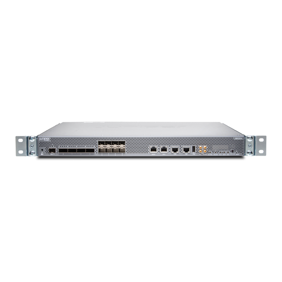
Junos Trio chipset for increased scalability of Layer 2 and Layer 3 packet forwarding, buffering, and queuing. The MX204 router is compact and one rack unit (1 U) tall. Several routers can be stacked in a single floor-to-ceiling rack for increased port density per unit of floor space. - Page 5 Figure 1: Front View of the MX204 Router Figure 2 on page 2 Figure 3 on page 2 shows the rear of the fully configured routers. Figure 2: Rear View of the AC-Powered MX204 Router Fan modules Power supply modules (AC) —...
-
Page 6: Step 1: Prepare The Site For Mx204 Installation
Tools Required to Prepare the MX204 Router for Installation | 8 MX204 Router Rack Requirements The MX204 router can be installed in a standard 19-in. rack. Many types of racks are acceptable, including four-post (telco) racks and open-frame racks. Table 1 on page 4 summarizes rack requirements and specifications for the router. - Page 7 Table 1: Rack Requirements and Specifications for an MX204 Router Rack Requirement Guidelines Rack type and mounting bracket Use a four-post rack. You can mount the router on any four-post rack that hole spacing provides bracket holes or hole patterns spaced at 1 U (1.75-in./4.44-cm) increments and that meets the size and strength requirements specified in this table.
- Page 8 (Continued) Table 1: Rack Requirements and Specifications for an MX204 Router Rack Requirement Guidelines Rack size and strength • Cabinets, Racks, Panels, Ensure that the rack is 19-in. wide as defined in and Associated Equipment (document number EIA-310–D) published by...
-
Page 9: Router Clearance Requirements
If you are mounting an MX204 in a rack with other equipment, ensure that the exhaust from the other equipment does not blow into the intake vents of the MX204 chassis. -
Page 10: Router Cooling And Airflow Requirements
Figure 5: Clearance Requirements for Airflow and Hardware Maintenance for the MX204 Router Cooling and Airflow Requirements • The router has front-to-back or airflow out (AFO) cooling system. Air is pulled through the front of the chassis toward the fan tray, from where it is exhausted out of the system. The power supplies are self-cooling and are located in the rear of the router. -
Page 11: Tools Required To Prepare The Mx204 Router For Installation
Figure 6: Airflow Through the MX204 Router Tools Required to Prepare the MX204 Router for Installation • Blank panels to cover any slots not occupied by a component • Mounting brackets, supplied with the router • Sixteen screws for securing the mounting brackets to the chassis, supplied with the router •... - Page 12 Figure 7: Attaching the Mounting Brackets Using a Phillips (+) number 2 screwdriver, secure the mounting brackets to the router using the mounting screws. With one person on each side, hold on to the bottom of the chassis and carefully lift it so that the mounting brackets contact the rack rails.
- Page 13 Figure 9: Router Secured by Front-Mounting Brackets On the rear of the chassis, slide the rear-mounting brackets on either side of the chassis until the rear-mounting brackets contact the rack rails (see Figure 10 on page 10). The rear-mounting brackets on each side of the chassis are movable. You can adjust the brackets according to the depth of the rack.
-
Page 14: Step 3: Connect The Grounding Cable
Minimum recommendations are 14–10 AWG (2–5.3 mm²) stranded wire, 60° C wire, or as permitted by local code. To ground the MX204 router: 1. Verify that a licensed electrician has attached the cable lug provided with the router to the grounding cable. -
Page 15: Step 4: Connect External Devices And Cables
Connect the Router to a Console Device | 14 Connect the Router to External Clocking and Timing Devices | 16 Figure 13 on page 13 shows the front panel of the MX204 router. All the connections to the router are made through the front panel. -
Page 16: Connect The Router To A Network For Out-Of-Band Management
Figure 13: MX204 Front Panel Ports, LEDs, and Button Rate-selectable ports RESET button — — Management (MGMT) port SSD0 LED — — BITS port with LEDs Alarm (ALM) LED — — USB port OK/FAIL LED — — 1PPS and 10MHz GPS input and output Time of day (ToD) port with LEDs —... -
Page 17: Connect The Router To A Console Device
Figure 14: Out-of-Band Management Cable Connector Table 2: Out-of-Band Management Port on the MX204 Router Callout Label Description MGMT Dedicated management channel for device maintenance. It is also used by system (See Figure 13 on page administrators to monitor and manage the router remotely. - Page 18 • Data bits—8 • Stop bits—1 • Flow control—none Figure 15: Console and Auxiliary Cable Connector Figure 16: Connecting the MX204 Router to a Management Console Through a Console Server Figure 17: Connecting the MX204 Router Directly to a Management Console...
-
Page 19: Connect The Router To External Clocking And Timing Devices
Table 3: Console Port on the MX204 Router Callout Label Description Connect a laptop or console terminal to configure the router. (See Figure 13 on page Connect the Router to External Clocking and Timing Devices IN THIS SECTION Connect 1-PPS and 10-MHz Timing Devices to the Router | 16... -
Page 20: Connect A Time-Of-Day Device To The Router
Table 4: Clocking Port on the MX204 Router Callout Label Description 10MHz GPS input and output ports. (See Figure 13 on page 1PPS Connect a Time-of-Day Device to the Router A time-of-day port—labeled ToD—on the front panel of the router enables you to connect external timing devices. -
Page 21: Step 5: Connect Power Cables
Depending on the configuration, your router uses either AC or DC power supplies. Perform the appropriate procedures for each power supply in your router. The power supplies are hot-insertable and are field-replaceable units (FRUs). MX204 supports two power supply modules. The power supplies install in the rear of the chassis in the slots provided. -
Page 22: Connect Power To An Ac Router
Connect Power to an AC Router Table 7: MX204 AC Power System Input Voltage Item Specification AC input voltage Operating range: 90–264 VAC Locate power cords that have a plug appropriate for your geographical location. Attach an ESD grounding strap to your bare wrist and connect the strap to one of the ESD points on the chassis. -
Page 23: Connect Power To A Dc Router
Figure 18: Connecting an AC Power Cord to an MX204 AC Power Supply Connect Power to a DC Router Table 8: MX204 DC Power System Input Voltage Item Specification DC input voltage Operating range: –44 through –72 VDC Switch off the dedicated customer-site circuit breakers. Ensure that the voltage across the DC power source cable leads is 0 V and that there is no chance that the cable leads might become active during installation. - Page 24 NOTE: The DC power source cables required is 14–16 AWG with ring lug (Molex 190700069 or equivalent) (not provided). CAUTION: Ensure that each power cable lug seats flush against the surface of the terminal block as you are tightening the screws. Ensure that each screw is properly threaded into the terminal.
-
Page 25: Step 6: Perform Initial Software Configuration
Figure 19: Connecting a DC Power Cable to an MX204 DC Power Supply Step 6: Perform Initial Software Configuration IN THIS SECTION Enter Configuration Mode | 22 Configure User Accounts and Passwords | 23 Configure System Attributes | 24 Commit the Configuration | 25 This procedure connects the router to the network but does not enable it to forward traffic. -
Page 26: Configure User Accounts And Passwords
3. Start the CLI. root# cli root@host> 4. Enter configuration mode. root@host> configure [edit] root@host# Configure User Accounts and Passwords For information about using an encrypted password or an SSH public key string (DSA or RSA), see Configuring the Root Password user 1. -
Page 27: Configure System Attributes
Configure System Attributes 1. Configure the name of the router. If the name includes spaces, enclose the name in quotation marks (“ ”). [edit] host-name root@host# set system host-name 2. Configure the router’s domain name. [edit] root@host# set system domain-name domain-name 3. -
Page 28: Commit The Configuration
7. Configure the Telnet service at the [edit system services] hierarchy level. [edit] root@host# set system services telnet Commit the Configuration 1. (Optional) Display the configuration to verify that it is correct. [edit] root@host# show system { host-name ; host-name domain-name ;... - Page 29 WARNING: See installation instructions before connecting the router. This is a summary of safety warnings. For a complete list of warnings for this router, including translations, see the MX204 Universal Routing Platform Hardware Guide https:/ / www.juniper.net/documentation/. WARNING: The intrabuilding port(s) of the router is suitable for connection to intrabuilding or unexposed wiring or cabling only.
- Page 30 MX204 Universal Routing Platform Hardware Guide https:/ / www.juniper.net/documentation/. To prevent injury, keep your back straight and lift with your legs, not your back. Do not attempt to lift the chassis by the power supply handles. • Mount the router at the bottom of the rack if it is the only unit in the rack.
- Page 31 Networks, Inc. in the United States and other countries. All other trademarks, service marks, registered marks, or registered service marks are the property of their respective owners. Juniper Networks assumes no responsibility for any inaccuracies in this document. Juniper Networks reserves the right to change, modify, transfer, or otherwise revise this publication without notice.
Need help?
Do you have a question about the MX204 and is the answer not in the manual?
Questions and answers