Sign In
Upload
Manuals
Brands
Teledyne Manuals
Test Equipment
T700
Teledyne T700 Manuals
Manuals and User Guides for Teledyne T700. We have
3
Teledyne T700 manuals available for free PDF download: Operation Manual, User Manual
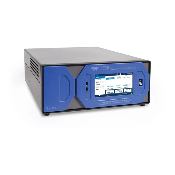
Teledyne T700 Operation Manual (392 pages)
Dynamic Dilution Calibrator
Brand:
Teledyne
| Category:
Test Equipment
| Size: 10.71 MB
Table of Contents
Table of Contents
13
Part I - General Information
23
Introduction
25
T700 Calibrator Overview
25
Features
25
Options
26
Table 1-1: Analyzer Options
26
Specifications and Approvals
29
Specifications
29
Table 2-1: T700 Dilution System Specifications
29
Table 2-2: T700 Dilution Electrical and Physical Specifications
29
Approvals and Certifications
30
Safety
30
Table 2-3: T700 Specifications for Optional Ozone Generator
30
Table 2-4: T700 Specifications for Optional O
30
Emc
31
Other Type Certifications
31
Getting Started
33
Unpacking and Initial Setup
33
Ventilation Clearance
34
Calibrator Layout
34
Front Panel
35
Figure 3-1: T700 Front Panel Layout
35
Table 3-1: Display Screen and Touch Control Description
36
Figure 3-3: Display/Touch Control Screen Mapped to Menu Charts
37
Rear Panel
38
Figure 3-4: T700 Rear Panel Layout
38
Table 3-2: Rear Panel Description
39
Internal Layout
40
Figure 3-5: T700 Internal Layout - Top View - Base Unit
40
Figure 3-6: T700 Internal Layout - Top View - with Optional O
41
Generator and Photometer
41
Connections and Setup
42
Connecting Power
42
Electrical Connections
42
Connecting Analog Outputs
43
Connecting the Status Outputs
43
Figure 3-7: T700 Analog Output Connector
43
Figure 3-8: Status Output Connector
44
Table 3-3: Status Output Pin Assignments
44
Connecting the Control Inputs
45
Table 3-4: T700 Control Input Pin Assignments
45
Figure 3-9: T700 Digital Control Input Connectors
46
Connecting the Control Outputs
47
Figure 3-10: T700 Digital Control Output Connector
47
Table 3-5: T700 Control Output Pin Assignments
47
Connecting the External Valve Driver Option
48
Figure 3-11: T700 Rear Panel Valve Driver Installed
48
Connecting the Communications Interfaces
49
Figure 3-12: Valve Driver PCA Layout
49
Figure 3-13: Rear Panel Connector Pin-Outs for RS-232 Mode
51
Figure 3-14: Default Pin Assignments for CPU COMM Port Connector (RS-232)
52
Figure 3-15: Jumper and Cables for Multidrop Mode
54
Figure 3-16: RS-232-Multidrop PCA Host/Analyzer Interconnect Diagram
55
About Calibration Gas
56
About Diluent Gas (Zero Air)
56
Pneumatic Connections
56
Table 3-6: NIST Standards for CO
57
Table 3-10: NIST Standards for O
58
Table 3-7: NIST Standards for CO
58
Table 3-8: NIST Standards for H
58
Table 3-9: NIST Standards for CH
58
Table 3-11: NIST Standards for so
59
Table 3-12: NIST Standards for no
59
Table 3-13: NIST Standards for Propane (C 3 H 8 )
59
Connecting Calibration Source Gas to the T700 Calibrator
60
Connecting Diluent Gas to the Calibrator
60
Connecting Gas Outputs from the Calibrator
61
Figure 3-17: Set up for T700 - Connecting the Basic T700 to a Sample Manifold
61
Figure 3-18: Set up for T700 - Connecting the T700 to a Sample Manifold
62
Figure 3-19: Set up for T700 - Connecting the T700 to a Calibration Manifold
63
Figure 3-20: Set up for T700 - Connecting the T700 to a Dual Span Gas / Zero Air Manifold
64
Figure 3-21: T700 Pneumatic Diagram - Base Unit
65
Other Pneumatic Connections
65
Figure 3-22: Internal Pneumatics for T700 Calibrator with Optional O
66
Table 3-14: Operating Mode Valve States for T700 Calibrator with Optional O
66
Figure 3-23: Internal Pneumatics for T700 Calibrator with Optional O
68
Table 3-15: Operating Mode Valve States for T700 Calibrator with Optional O
68
Figure 3-24: Basic T700 with Multiple Calibration Gas Mfcs
70
Figure 3-25: T700 with Multiple Calibration Gas Mfcs and O
71
Options 1A and 2A Installed
71
Figure 3-26: Permeation Tube Gas Generator Option
72
Figure 3-27: Pneumatic Diagram of T700 with Permeation Generator
73
Permeation Tube Setup for the T700
76
Permeation Tube Calculation
77
Figure 3-28. Rear Panel with Dual Output Option
78
Startup, Functional Checks, and Initial Calibration
79
Figure 3-29: Internal Pneumatics for T700 Calibrator with Optional Dual Gas Output
79
Start up
79
Warning Messages
79
Table 3-16: Possible Warning Messages at Start-Up
80
Functional Checks
82
Default Gas Types
83
Setting up the Calibration Gas Inlet Ports
83
Table 3-17: T700 Default Gas Types
83
User Defined Gas Types
83
User Defined Gas Types - General
83
User Defined Gas Types - Defining the Gas Name
85
User Defined Gas Types - Setting the MOLAR MASS
86
Enabling and Disabling Gas Types
88
Defining Calibration Source Gas Cylinders
89
Setting up the Ports with Single Gas Cylinders
89
Table 3-18: T700 Units of Measure List
90
Setting up the Ports with Multiple Gas Cylinders
91
Bnch (Bench)
92
Cnst (Constant)
92
Ref (Reference)
92
Selecting an Operating Mode for the O3 Generator
92
Setting the T700'S Total Gas Flow Rate
93
Part II - Operating Instructions
95
Overview of Operating Modes and Basic Operation
97
Figure 4-1: Front Panel Display
98
Table 4-1: Calibrator Operating Modes
99
Standby Mode
100
Table 4-2: Status of Internal Pneumatics During STANDBY Mode
100
Figure 4-2: Gas Flow through T700 with O Generator and Photometer Options During STANDBY
101
Test Functions
101
Figure 4-3: Viewing T700 Test Functions
102
Table 4-3: Test Functions Defined
103
Figure 4-4: Gas Flow through Basic T700 in GENERATE Mode
104
Generate Mode
104
Table 4-4: Status of Internal Pneumatics During GENERATE Mode
104
Figure 4-5: Gas Flow through T700 with O
105
Figure 4-5: Gas Flow through T700 with O Options When Generating Non-O Source Gas
105
Figure 4-6: Gas Flow through T700 with O Options When Generating O
105
Figure 4-7: Gas Flow through T700 with O
105
GENERATE AUTO: Basic Generation of Calibration Mixtures
106
Determining the Source Gas Flow Rate
108
GENERATE MAN: Generating Calibration Mixtures Manually
108
Determining the Diluent Gas Flow Rate
109
Determining the Diluent Gas Flow Rate with the Optional O
109
Setting the Source Gas and Diluent Flow Rates Using the GENERATE man Menu
110
Choosing an Input Concentration for the no
111
GENERATE GPT: Performing a Gas Phase Titration Calibration
111
GPT Theory
111
Determining the TOTAL FLOW for GPT Calibration Mixtures
112
T700 Calibrator GPT Operation
113
Table 4-5: Status of Internal Pneumatics During GENERATE GPT Mode
113
Initiating a GPT Calibration Gas Generation
114
GENERATE GPTPS: Performing a Gas Phase Titration Pre-Set
115
T700 Calibrator GPTPS Operation
115
Table 4-6: Status of Internal Pneumatics During GENERATE GPTPS Mode
115
Figure 4-8: Gas Flow through T700 with O
116
Initiating a GPT Pre-Set
117
Figure 4-9: Gas Flow through T700 with O Options When in PURGE Mode
118
GENERATE PURGE: Activating the T700'S Purge Feature
118
Table 4-7: Internal Pneumatics During Purge Mode
118
GENERATE ACT>: VIEWING CONCENTRATIONS Generated from Multi-Gas Cylinders
120
Using the T700 Calibrator as an O Photometer
120
Automatic Calibration Sequences
121
SETUP SEQ: Programming Calibration Sequences
121
Table 4-8: Automatic Calibration SEQUENCE Set up Attributes
121
Table 4-9: Calibration SEQUENCE Step Instruction
122
Activating a Sequence from the T700 Front Panel
123
Naming a Sequence
124
Setting the Repeat Count for a Sequence
125
Using the T700'S Internal Clock to Trigger Sequences
126
Setting up Control Inputs for a Sequence
129
Setting up Control Outputs for a Sequence
130
Setting the PROGRESS Reporting Mode for the Sequences
132
Table 4-10: Sequence Progress Reporting Mode
132
Adding Sequence Steps
133
The GENERATE Step
134
The GPT Step
135
The GPTPS Step
136
The PURGE Step
137
The STANDBY Step
137
The DURATION Step
138
The EXECSEQ Step
138
The CC OUTPUT Step
140
The MANUAL Gas Generation Step
141
Deleting or Editing an Individual Step in a Sequence
142
Deleting a Sequence
143
Setup Cfg
144
SETUP CLK: Setting the Internal Time-Of-Day Clock and Adjusting Speed
145
Setting the Internal Clock's Time and Day
145
Adjusting the Internal Clock's Speed
146
Setup Pass
147
Table 4-11: Password Levels
147
SETUP COMM: Communications Ports
149
ID (Machine Identification)
149
COM1 and COM2 (Mode, Baud Rate and Test Port)
150
INET (Ethernet)
150
Setup more Flow
150
SETUP more VARS: Internal Variables (VARS)
150
Table 4-12: Variable Names (VARS)
150
SETUP more DIAG: Diagnostics Functions
153
Configuring the Test Channel Analog Output
153
Figure 4-10: T700 the TEST CHANNEL Connector
153
Table 4-13: DIAG - Analog I/O Functions
153
TEST CHAN OUTPUT: Using the TEST Channel Analog Output
153
Selecting a Test Channel Function to Output
156
Table 4-14: Test Channels Functions Available on the T700'S Analog Output
156
Table 4-15: Analog Output Voltage Range Min/Max
158
Test Channel Voltage Range Configuration
158
Turning the Test Channel Over-Range Feature ON/OFF
159
Adding a Recorder Offset to the Test Channel
160
Test Channel Calibration
162
Figure 4-11: Setup for Calibrating the TEST CHANNEL
165
Table 4-16: Voltage Tolerances for the TEST CHANNEL Calibration
165
AIN Calibration
167
SETUP LVL: Setting up and Using LEADS (Dasibi) Operating Levels
168
Dot Commands
168
General Information about LEADS LEVELS
168
Activating an Existing LEVEL
169
Levels
169
Programming New LEVELS
170
Creating a GENERATE LEVEL
171
Creating a GPT LEVEL
172
Creating a GPTPS LEVEL
173
Creating a MANUAL LEVEL
174
Editing or Deleting a LEVEL
175
CONFIGURING LEVEL Status Blocks
176
Communications Setup and Remote Operation
177
Data Terminal/Communication Equipment (DTE DCE)
177
Communication Modes, Baud Rate and Port Testing
178
Communication Modes
178
Table 5-1: COMM Port Communication Modes
178
COM Port Baud Rate
181
COM Port Testing
182
Remote Access Via the Ethernet
183
Configuring the Ethernet Interface Using DHCP
183
Table 5-2: Ethernet Status Indicators
183
RS-485 (Option)
183
Table 5-3: Lan/Internet Configuration Properties
184
Manually Configuring the Network IP Addresses
186
Changing the Calibrator's HOSTNAME
188
USB PORT (Option) for Remote Access
189
Remote Operation
191
Computer Mode
191
Remote Control Via APICOM
191
Interactive Mode
192
Remote Control Via a Terminal Emulation Program
192
Figure 6-1: APICOM Remote Control Program Interface
192
Help Commands in Interactive Mode
192
Table 6-1: Terminal Mode Software Commands
192
Command Syntax
193
Data Types
194
Status Reporting
194
Table 6-2: Teledyne API Serial I/O Command Types
194
General Message Format
195
Remote Access by Modem
195
Password Security for Serial Remote Communications
198
Calibration and Verification
199
Viewing the Performance Statistics for the T700'S Mfc's
199
Calibrating the Output of the T700'S Mfc's
201
Table 7-1: Examples of MFC Calibration Points
201
Figure 7-1: Location of MFC Outlet Ports
202
Setup for Verification and Calibration of the T700'Smfc's
202
Verifying and Calibrating the T700'S Mfc's
203
Verifying and Calibrating the T700'S Optional O
204
Setup for Verifying O3 Photometer Performance
204
Figure 7-2: Set up for Verifying Optional O
204
Photometer
204
Verifying O3 Photometer Performance
205
Setup for Calibration of the O3 Photometer
206
Figure 7-3: External Photometer Validation Setup - Direct Connections
206
Setup Using Direct Connections
206
Calibration Manifold Exhaust/Vent Line
207
Setup Using a Calibration Manifold
207
Performing an O Photometer External Calibration
207
Figure 7-4: External Photometer Validation Setup with Calibration Manifolds
207
Photometer Zero Calibration
208
Photometer Span Calibration
209
O3 Photometer Dark Calibration
210
O3 Photometer Gas Flow Calibration
211
O3 Photometer Backpressure Compensation Calibration
212
Calibrating the O Generator
213
Setup for Verification and Calibration the Ogenerator
213
Figure 7-5: O 3 Generator Calibration Setup - Direct Connections
213
Setup Using Direct Connections
213
O3 Generator Calibration Procedure
215
Viewing O Generator Calibration Points
215
Adding or Editing O Generator Calibration Points
216
Deleting O Generator Calibration Points
217
Generator Calibration Points on / off
218
Turning O
218
Performing an Automatic Calibration of the Optional O
219
T700 Gas Pressure Sensor Calibration
220
Table 7-2: T700 Pressure Sensor Calibration Setup
220
Figure 7-6: Pressure Monitor Points - T700 - Basic Unit
221
Figure 7-7: Pressure Monitor Points - T700 with O
221
Calibrating the Diluent, Cal Gas Optional O
222
Generator Pressure Sensors
222
Calibrating the Optional O
223
Photometer Sample Gas Pressure Sensors
223
Part III - Maintenance and Service
225
Maintenance
227
Maintenance Schedule
227
Table 8-1: T700 Maintenance Schedule
228
Maintenance Procedures
229
Auto Leak Check
229
Equipment Required
229
Figure 8-1: Bypassing the Photometer Sensor PCA and Pump
229
Setup Auto Leak Check
229
Figure 8-2: Gas Port Setup for Auto-Leak Check Procedure
230
Figure 8-3: Gas Flow for Auto-Leak Check Procedure of Base Model T700'S
231
Figure 8-4: Gas Flow for Auto-Leak Check Procedure of T700'S with Optional Photometer
231
Performing the Auto Leak Check Procedure
232
Returning the T700 to Service after Performing an Auto Leak Check
232
Cleaning or Replacing the Absorption Tube
233
UV Source Lamp Adjustment
234
UV Source Lamp Replacement
235
Figure 8-5: Photometer Assembly - Lamp Adjustment / Installation
235
Ozone Generator UV Lamp Adjustment or Replacement
236
Figure 8-6: O 3 Generator Temperature Thermistor and DC Heater Locations
236
Figure 8-7: Location of O
237
Troubleshooting and Service
241
General Troubleshooting
241
Fault Diagnosis with WARNING Messages
242
Table 9-1: Warning Messages in Front Panel Display Param Field
245
Fault Diagnosis with Test Functions
246
Table 9-2: Test Functions - Indicated Failures
247
Using the Diagnostic Signal I/O Function
248
Figure 9-1: Example of Signal I/O Function
249
Using the Analog Output Test Channel
250
Table 9-3: Test Channel Outputs as Diagnostic Tools
250
Using the Internal Electronic Status Leds
251
CPU Status Indicator
251
Relay PCA Status Leds
251
C Bus Watchdog Status Leds
251
Figure 9-2: CPU Status Indicator
251
Table 9-4: Relay PCA Watchdog LED Failure Indications
251
Figure 9-3: Relay PCA Status LEDS Used for Troubleshooting
252
O 3 Option Status Leds
252
Table 9-5: Relay PCA Status LED Failure Indications
252
Valve Driver PCA STATUS Leds
253
Figure 9-4: Valve Driver PCA Status LEDS Used for Troubleshooting
253
Figure 10-5: Relay PCA
253
Table 9-6: Valve Driver Board Watchdog LED Failure Indications
253
Table 9-7: Relay PCA Status LED Failure Indications
253
Subsystem Checkout
254
Verify Subsystem Calibration
254
AC Main Power
254
DC Power Supply
255
Figure 9-5: Location of DC Power Test Points on Relay PCA
255
Table 9-8: DC Power Test Point and Wiring Color Codes
255
I 2 C Bus
256
Touchscreen Interface
256
Table 9-9: DC Power Supply Acceptable Levels
256
LCD Display Module
257
Relay PCA
257
Valve Driver PCA
257
Table 9-10: Relay PCA Control Devices
257
Input Gas Pressure / Flow Sensor Assembly
258
PHOTOMETER O3 Generator Pressure/Flow SENSOR Assembly
259
Motherboard
260
A/D Functions
260
Test Channel / Analog Outputs Voltage
260
Table 9-11: Analog Output Test Function - Nominal Values Voltage Outputs
261
Status Outputs
262
Table 9-12: Status Outputs Check
262
Control Inputs
263
Control Outputs
263
Table 9-13: T700 Control Input Pin Assignments and Corresponding Signal I/O Functions
263
Cpu
264
The Calibrator Doesn't Appear on the Lan or Internet
264
Table 9-14: Control Outputs Pin Assignments and Corresponding Signal I/O Functions Check
264
Communications
265
General RS-232 Troubleshooting
265
Troubleshooting Calibrator/Modem or Terminal Operation
265
Temperature Problems
266
Box / Chassis Temperature
266
Photometer Sample Chamber Temperature
266
UV Lamp Temperature
266
Ozone Generator Temperature
267
Troubleshooting the Optional O Photometer
267
Dynamic Problems with the Optional O3 Photometer
267
Noisy or Unstable O
267
Readings at Zero
267
Cannot Span
268
Cannot Zero
268
Noisy, Unstable, or Non-Linear Span O Readings
268
Slow Response to Changes in Concentration
268
The Analog Output Signal Level Does Not Agree with Front Panel Readings
268
Checking Measure / Reference Valve
269
Checking the UV Lamp Power Supply
270
Troubleshooting the Optional O Generator
271
Checking the UV Source Lamp Power Supply
271
Service Procedures
272
Disk-On-Module Replacement Procedure
272
Technical Assistance
272
Frequently Asked Questions (Faqs)
273
Principles of Operation
275
Basic Principles of Dynamic Dilution Calibration
275
Gas Phase Titration Mixtures for O3 and NO2
277
Pneumatic Operation
278
Gas Flow Control
279
Diluent and Source Gas Flow Control
279
Components
280
Figure 10-1: Location of Gas Flow Control Assemblies for T700'S with O
280
Flow Control Assemblies for Optional O
280
Critical Flow Orifices
281
Figure 10-2: Flow Control Assembly & Critical Flow Orifice
281
Internal Gas Pressure Sensors
282
Electronic Operation
283
Overview
283
Figure 10-3: T700 Electronic Block Diagram
283
Cpu
284
Disk-On-Module (DOM)
285
Figure 10-4: T700 CPU Board Annotated
285
Flash Chip
285
Relay PCA
286
Figure 10-6: Heater Control Loop Block Diagram
287
Heater Control
287
Relay PCA Status Leds & Watch Dog Circuitry
287
Valve Control
287
Figure 10-7: Status LED Locations - Relay PCA
288
Relay PCA Watchdog Indicator (D1)
288
Table 10-1: Relay PCA Status Leds
288
Valve Driver PCA
289
Figure 10-8: Status LED Locations - Valve Driver PCA
289
Valve Driver PCA Watchdog Indicator
289
Motherboard
290
A to D Conversion
290
Analog Outputs
290
Sensor Inputs
290
Thermistor Interface
290
External Digital I/O
291
I 2 C Data Bus
291
Power-Up Circuit
291
Input Gas Pressure Sensor PCA
291
Power Supply and Circuit Breaker
292
Figure 10-9: T700 Power Distribution Block Diagram
292
Front Panel Touchscreen/Display Interface
293
Front Panel Interface PCA
293
Figure 10-10: Front Panel Display Interface Block Diagram
293
Software Operation
294
Figure 10-11: Schematic of Basic Software Operation
294
Generator Operation
295
Principle of Photolytic O
295
Generation
295
Figure 10-12: O Generator Internal Pneumatics
295
Figure 10-13: O
296
O3 Generator - Pneumatic Operation
296
O3 Generator - Electronic Operation
297
Figure 10-14: O
297
Figure 10-15: O Generator Electronic Components Location
298
O 3 Generator Temperature Control
298
Photometer Operation
299
Pneumatic Sensor for the O
299
Generator
299
Figure 10-16: O
299
Measurement Method
300
Calculating O Concentration
300
Table 10-2: T700 Photometer Measurement / Reference Cycle
301
The Measurement / Reference Cycle
301
Figure 10-17: O Photometer Gas Flow - Measure Cycle
302
Figure 10-18: O
302
Figure 10-19: O
303
Interferent Rejection
303
The Absorption Path
303
Figure 10-20: O Photometer Layout - Top Cover Removed
304
Photometer Layout
304
Photometer Pneumatic Operation
304
Figure 10-21: O
305
Photometer Electronic Operation
305
O 3 Photometer Temperature Control
306
Pneumatic Sensors for the O
306
Photometer
306
Advertisement
Teledyne T700 Operation Manual (366 pages)
Dynamic Dilution Calibrator
Brand:
Teledyne
| Category:
Test Equipment
| Size: 6.9 MB
Table of Contents
About this Manual
9
Table of Contents
11
Introduction
21
T700 Calibrator Overview
21
Features
21
Options
22
Table 1-1: Calibrator Options
22
Specifications and Approvals
25
Specifications
25
Table 2-1: T700 Dilution System Specifications
25
Table 2-2: T700 Dilution Electrical and Physical Specifications
25
Approvals and Certifications
26
Safety
26
Table 2-3: T700 Specifications for Optional Ozone Generator
26
Table 2-4: T700 Specifications for Optional O
26
Emc
27
Other Type Certifications
27
Getting Started
29
Unpacking and Initial Setup
29
Ventilation Clearance
30
Calibrator Layout
30
Front Panel
31
Figure 3-1: T700 Front Panel Layout
31
Table 3-1: Display Screen and Touch Control Description
32
Rear Panel
34
Figure 3-4: T700 Rear Panel Layout
34
Table 3-2: Rear Panel Description
35
Internal Layout
36
Figure 3-5: T700 Internal Layout - Top View - Base Unit
36
Figure 3-6: T700 Internal Layout - Top View - with Optional O
37
Generator and Photometer
37
Connections and Setup
38
Electrical Connections
38
Connecting Power
38
Connecting Analog Outputs
39
Connecting the Status Outputs
39
Figure 3-7: T700 Analog Output Connector
39
Figure 3-8: Status Output Connector
40
Table 3-3: Status Output Pin Assignments
40
Connecting the Control Inputs
41
Table 3-4: T700 Control Input Pin Assignments
41
Figure 3-9: T700 Digital Control Input Connectors
42
Connecting the Control Outputs
43
Figure 3-10: T700 Digital Control Output Connector
43
Table 3-5: T700 Control Output Pin Assignments
43
Connecting the External Valve Driver Option
44
Connecting the Communications Interfaces
46
Figure 3-17: Rear Panel Connector Pin-Outs for RS-232 Mode
48
Figure 3-18: Default Pin Assignments for CPU COMM Port Connector (RS-232)
49
Figure 3-19: Jumper and Cables for Multidrop Mode
51
Figure 3-20: RS-232-Multidrop PCA Host/Analyzer Interconnect Diagram
52
Pneumatic Connections
53
About Diluent Gas (Zero Air)
53
About Calibration Gas
54
Table 3-7: NIST Standards for CO
54
Table 3-8: NIST Standards for CO
55
Table 3-9: NIST Standards for H
55
Table 3-10: NIST Standards for CH
55
Table 3-11: NIST Standards for O
55
Table 3-12: NIST Standards for so
56
Table 3-13: NIST Standards for no
56
Table 3-14: NIST Standards for Propane
56
Connecting Diluent Gas to the Calibrator
57
Connecting Calibration Source Gas to the T700 Calibrator
57
Connecting Gas Outputs from the Calibrator
58
Figure 3-21: Set up for T700 - Connecting the Basic T700 to a Sample Manifold
58
Figure 3-22: Set up for T700 - Connecting the T700 to a Sample Manifold
59
Figure 3-23: Set up for T700 - Connecting the T700 to a Calibration Manifold
60
Figure 3-24: Set up for T700 - Connecting the T700 to a Dual Span Gas / Zero Air Manifold
61
Other Pneumatic Connections
62
Figure 3-25: T700 Pneumatic Diagram - Base Unit
62
Figure 3-26: Internal Pneumatics for T700 Calibrator with Optional O
63
Table 3-15: Operating Mode Valve States for T700 Calibrator with Optional O
63
Generator
63
Figure 3-27: Internal Pneumatics for T700 Calibrator with Optional O
65
Table 3-16: Operating Mode Valve States for T700 Calibrator with Optional O
65
Figure 3-28: Basic T700 with Multiple Calibration Gas Mfcs
67
Figure 3-29: T700 with Multiple Calibration Gas Mfcs and O
68
Options 1A and 2A Installed
68
Permeation Tube Setup for the T700
73
Permeation Tube Calculation
74
Startup, Functional Checks, and Initial Calibration
76
Start up
76
Warning Messages
77
Table 3-17: Possible Warning Messages at Start-Up
77
Functional Checks
79
Setting up the Calibration Gas Inlet Ports
80
Default Gas Types
80
User Defined Gas Types
80
User Defined Gas Types - General
80
Table 3-18: T700 Default Gas Types
80
User Defined Gas Types - Defining the Gas Name
82
User Defined Gas Types - Setting the MOLAR MASS
83
Enabling and Disabling Gas Types
85
Defining Calibration Source Gas Cylinders
86
Setting up the Ports with Single Gas Cylinders
86
Table 3-19: T700 Units of Measure List
87
Setting up the Ports with Multiple Gas Cylinders
88
Selecting an Operating Mode for the O3 Generator
89
Cnst (Constant)
89
Bnch (Bench)
89
Setting the T700"S Total Gas Flow Rate
90
Overview of Operating Modes and Basic Operation
93
Figure 4-1: Front Panel Display
94
Table 4-1: Calibrator Operating Modes
95
Standby Mode
96
Table 4-2: Status of Internal Pneumatics During STANDBY Mode
96
Test Functions
97
Figure 4-2: Gas Flow through T700 with O
97
Figure 4-3: Viewing T700 Test Functions
98
Table 4-3: Test Functions Defined
99
Generate Mode
100
Figure 4-4: Gas Flow through Basic T700 in GENERATE Mode
100
Table 4-4: Status of Internal Pneumatics During GENERATE Mode
100
Figure 4-5: Gas Flow through T700 with O
101
Figure 4-6: Gas Flow through T700 with O
101
GENERATE > AUTO: Basic Generation of Calibration Mixtures
102
GENERATE > MAN: Generating Calibration Mixtures Manually
104
Determining the Source Gas Flow Rate
104
Determining the Diluent Gas Flow Rate
105
Determining the Diluent Gas Flow Rate with the Optional O 3 Generator Installed
105
Setting Source Gas and Diluent Flow Rates Using the GENERATE > man Menu
106
GENERATE > GPT: Performing a Gas Phase Titration Calibration
107
GPT Theory
107
Choosing an Input Concentration for the no
107
Determining the TOTAL FLOW for GPT Calibration Mixtures
108
T700 Calibrator GPT Operation
109
Figure 4-7: Gas Flow through T700 with O
109
Table 4-5: Status of Internal Pneumatics During GENERATE > GPT Mode
109
Initiating a GPT Calibration Gas Generation
110
GENERATE > GPTPS: Performing a Gas Phase Titration Pre-Set
111
T700 Calibrator GPTPS Operation
111
Table 4-6: Status of Internal Pneumatics During GENERATE > GPTPS Mode
111
Figure 4-8: Gas Flow through T700 with O
112
Options When in GPTPS Mode
112
Initiating a GPT Pre-Set
113
GENERATE > PURGE: Activating the T700"S Purge Feature
114
Figure 4-9: Gas Flow through T700 with O
114
Table 4-7: Internal Pneumatics During Purge Mode
114
GENERATE >ACT>: VIEWING CONCENTRATIONS Generated from Multi-Gas Cylinders
116
Using the T700 Calibrator as an O Photometer
116
Automatic Calibration Sequences
117
SETUP > SEQ: Programming Calibration Sequences
117
Table 4-8: Automatic Calibration SEQUENCE Set up Attributes
117
Table 4-9: Calibration SEQUENCE Step Instruction
118
Activating a Sequence from the T700 Front Panel
119
Naming a Sequence
120
Setting the Repeat Count for a Sequence
121
Using the T700"S Internal Clock to Trigger Sequences
122
Setting up Control Inputs for a Sequence
125
Setting up Control Outputs for a Sequence
126
Setting the PROGRESS Reporting Mode for the Sequences
128
Table 4-10: Sequence Progress Reporting Mode
128
Adding Sequence Steps
129
The GENERATE Step
130
The GPT Step
131
The GPTPS Step
132
The PURGE Step
133
The STANDBY Step
133
The DURATION Step
134
The EXECSEQ Step
135
The CC OUTPUT Step
136
The MANUAL Gas Generation Step
137
Deleting or Editing an Individual Step in a Sequence
138
Deleting a Sequence
139
Setup > Cfg
140
SETUP > CLK: Setting the Internal Time-Of-Day Clock and Adjusting Speed
141
Setting the Internal Clock"S Time and Day
141
Adjusting the Internal Clock"S Speed
142
Setup > Pass
143
Table 4-11: Password Levels
143
SETUP > COMM: Communications Ports
145
ID (Machine Identification)
145
INET (Ethernet)
146
COM1 and COM2 (Mode, Baud Rate and Test Port)
146
Setup > more > Flow
146
SETUP > more > VARS: Internal Variables (VARS)
146
Table 4-12: Variable Names (VARS)
146
Setup > more > Diag: Diagnostics Functions
149
TEST CHAN OUTPUT: Using the TEST Channel Analog Output
149
Configuring the Test Channel Analog Output
149
Figure 4-10: T700 the TEST CHANNEL Connector
149
Table 4-13: DIAG - Analog I/O Functions
149
Selecting a Test Channel Function to Output
152
Table 4-14: Test Channels Functions Available on the T700"S Analog Output
152
Test Channel Voltage Range Configuration
154
Table 4-15: Analog Output Voltage Range Min/Max
154
Turning the Test Channel Over-Range Feature ON/OFF
155
Adding a Recorder Offset to the Test Channel
156
Test Channel Calibration
157
Figure 4-11: Setup for Calibrating the TEST CHANNEL
160
Table 4-16: Voltage Tolerances for the TEST CHANNEL Calibration
160
AIN Calibration
162
SETUP > LVL: Setting up and Using LEADS (Dasibi) Operating Levels
163
General Information about LEADS LEVELS
163
Dot Commands
163
Levels
164
Activating an Existing LEVEL
164
Programming New LEVELS
165
Creating a GENERATE LEVEL
166
Creating a GPT LEVEL
167
Creating a GPTPS LEVEL
168
Creating a MANUAL LEVEL
169
Editing or Deleting a LEVEL
170
CONFIGURING LEVEL Status Blocks
171
Communications Setup and Operation
173
Data Terminal/Communication Equipment (DTE DCE)
173
Communication Modes, Baud Rate and Port Testing
174
Communication Modes
174
Table 5-1: COMM Port Communication Modes
174
COM Port Baud Rate
177
COM Port Testing
178
Remote Access Via the Ethernet
179
Configuring the Ethernet Interface Using DHCP
179
Table 5-2: Ethernet Status Indicators
179
RS-485 (Option)
179
Table 5-3: Lan/Internet Configuration Properties
180
Manually Configuring the Network IP Addresses
182
Changing the Calibrator"S HOSTNAME
184
USB PORT (Option) for Remote Access
185
Remote Operation
187
Computer Mode
187
Remote Control Via APICOM
187
Interactive Mode
188
Remote Control Via a Terminal Emulation Program
188
Help Commands in Interactive Mode
188
Figure 6-1: APICOM Remote Control Program Interface
188
Table 6-1: Terminal Mode Software Commands
188
Command Syntax
189
Data Types
190
Status Reporting
190
Table 6-2: Teledyne API Serial I/O Command Types
190
General Message Format
191
Remote Access by Modem
191
Password Security for Serial Remote Communications
194
Calibration and Verification
195
Viewing the Performance Statistics for the T700"S Mfc"S
195
Calibrating the Output of the T700"S Mfc"S
197
Table 7-1: Examples of MFC Calibration Points
197
Setup for Verification and Calibration of the T700'Smfc's
198
Figure 7-1: Location of MFC Outlet Ports
198
Verifying and Calibrating the T700"S Mfc"S
199
Verifying and Calibrating the T700'S Optional Ophotometer
201
Setup for Verifying O
201
Figure 7-2: Set up for Verifying Optional O
201
Verifying O
202
Photometer Performance
202
Setup for Calibration of the O Photometer
203
Setup Using Direct Connections
203
Figure 7-3: External Photometer Validation Setup - Direct Connections
203
Setup Using a Calibration Manifold
204
Calibration Manifold Exhaust/Vent Line
204
Performing an O Photometer External Calibration
204
Figure 7-4: External Photometer Validation Setup with Calibration Manifolds
204
Photometer Zero Calibration
205
Photometer Span Calibration
206
Photometer Dark Calibration
207
Photometer Gas Flow Calibration
208
Photometer Backpressure Compensation Calibration
209
Setup for Verification and Calibration the O 7.4.1.1. Setup Using Direct Connections
210
Generator
210
Figure 7-5: O 3 Generator Calibration Setup - Direct Connections
210
O 3 Generator Calibration Procedure
212
Viewing O Generator Calibration Points
212
Adding or Editing O Generator Calibration Points
213
Deleting O Generator Calibration Points
214
Turning O Generator Calibration Points on / off
215
Performing an Automatic Calibration of the Optional O Generator
216
T700 Gas Pressure Sensor Calibration
217
Table 7-2: T700 Pressure Sensor Calibration Setup
217
Figure 7-6: Pressure Monitor Points - T700 - Basic Unit
218
Figure 7-7: Pressure Monitor Points - T700 with O
218
Calibrating the Diluent, Cal Gas Optional O Generator Pressure Sensors
219
Calibrating the Optional O Photometer Sample Gas Pressure Sensors
220
Maintenance
221
Maintenance Schedule
221
Table 8-1: T700 Maintenance Schedule
222
Maintenance Procedures
223
Auto Leak Check
223
Equipment Required
223
Setup Auto Leak Check
223
Figure 8-1: Bypassing the Photometer Sensor PCA and Pump
223
Figure 8-2: Gas Port Setup for Auto-Leak Check Procedure
224
Figure 8-3: Gas Flow for Auto-Leak Check Procedure of Base Model T700"S
225
Figure 8-4: Gas Flow for Auto-Leak Check Procedure of T700"S with Optional Photometer
225
Performing the Auto Leak Check Procedure
226
Returning the T700 to Service after Performing an Auto Leak Check
226
Cleaning or Replacing the Absorption Tube
227
UV Source Lamp Adjustment
228
UV Source Lamp Replacement
229
Figure 8-5: Photometer Assembly - Lamp Adjustment / Installation
229
Ozone Generator UV Lamp Adjustment or Replacement
230
Figure 8-6: O 3 Generator UV Lamp Location
230
Troubleshooting and Service
231
General Troubleshooting
231
Fault Diagnosis with WARNING Messages
232
Table 9-1: Warning Messages in Front Panel Display Param Field
235
Fault Diagnosis with Test Functions
236
Table 9-2: Test Functions - Indicated Failures
237
Using the Diagnostic Signal I/O Function
238
Figure 9-1: Example of Signal I/O Function
239
Using the Analog Output Test Channel
240
Table 9-3: Test Channel Outputs as Diagnostic Tools
240
Using the Internal Electronic Status Leds
241
CPU Status Indicator
241
Relay PCA Status Leds
241
C Bus Watchdog Status Leds
241
Figure 9-2: CPU Status Indicator
241
Table 9-4: Relay PCA Watchdog LED Failure Indications
241
O 3 Option Status Leds
242
Figure 9-3: Relay PCA Status LEDS Used for Troubleshooting
242
Table 9-5: Relay PCA Status LED Failure Indications
242
Valve Driver PCA STATUS Leds
243
Figure 9-4: Valve Driver PCA Status LEDS Used for Troubleshooting
243
Figure 10-5: Relay PCA
243
Table 9-6: Valve Driver Board Watchdog LED Failure Indications
243
Table 9-7: Relay PCA Status LED Failure Indications
243
Subsystem Checkout
244
Verify Subsystem Calibration
244
AC Main Power
244
DC Power Supply
245
Figure 9-5: Location of DC Power Test Points on Relay PCA
245
Table 9-8: DC Power Test Point and Wiring Color Codes
245
I 2 C Bus
246
Touchscreen Interface
246
LCD Display Module
246
Table 9-9: DC Power Supply Acceptable Levels
246
Relay PCA
247
Valve Driver PCA
247
Table 9-10: Relay PCA Control Devices
247
Input Gas Pressure / Flow Sensor Assembly
248
PHOTOMETER O3 Generator Pressure/Flow SENSOR Assembly
249
Motherboard
250
A/D Functions
250
Test Channel / Analog Outputs Voltage
250
Table 9-11: Analog Output Test Function - Nominal Values Voltage Outputs
251
Status Outputs
252
Table 9-12: Status Outputs Check
252
Control Inputs
253
Control Outputs
253
Table 9-13: T700 Control Input Pin Assignments and Corresponding Signal I/O Functions
253
Cpu
254
The Calibrator Doesn"T Appear on the Lan or Internet
254
Table 9-14: Control Outputs Pin Assignments and Corresponding Signal I/O Functions Check
254
Communications
255
General RS-232 Troubleshooting
255
Troubleshooting Calibrator/Modem or Terminal Operation
255
Temperature Problems
256
Box / Chassis Temperature
256
Photometer Sample Chamber Temperature
256
UV Lamp Temperature
256
Ozone Generator Temperature
257
Troubleshooting the Optional O Photometer
257
Dynamic Problems with the Optional O3 Photometer
257
Noisy or Unstable O 3 Readings at Zero
257
Noisy, Unstable, or Non-Linear Span O Readings
258
Slow Response to Changes in Concentration
258
The Analog Output Signal Level Does Not Agree with Front Panel Readings
258
Cannot Zero
258
Cannot Span
258
Checking Measure / Reference Valve
259
Checking the UV Lamp Power Supply
260
Troubleshooting the Optional O Generator
261
Checking the UV Source Lamp Power Supply
261
Service Procedures
262
Disk-On-Module Replacement Procedure
262
Technical Assistance
263
Frequently Asked Questions (Faqs)
263
Principles of Operation
265
Basic Principles of Dynamic Dilution Calibration
265
Gas Phase Titration Mixtures for O and no
266
Pneumatic Operation
267
Gas Flow Control
268
Diluent and Source Gas Flow Control
268
Flow Control Assemblies for Optional O Components
269
Figure 10-1: Location of Gas Flow Control Assemblies for T700"S with O
269
Critical Flow Orifices
270
Figure 10-2: Flow Control Assembly & Critical Flow Orifice
270
Internal Gas Pressure Sensors
271
Electronic Operation
272
Overview
272
Figure 10-3: T700 Electronic Block Diagram
272
Cpu
273
Disk-On-Module (DOM)
274
Flash Chip
274
Figure 10-4: T700 CPU Board Annotated
274
Relay PCA
275
Valve Control
276
Heater Control
276
Relay PCA Status Leds & Watch Dog Circuitry
276
Figure 10-6: Heater Control Loop Block Diagram
276
Relay PCA Watchdog Indicator (D1)
277
Figure 10-7: Status LED Locations - Relay PCA
277
Table 10-1: Relay PCA Status Leds
277
Valve Driver PCA
278
Valve Driver PCA Watchdog Indicator
278
Figure 10-8: Status LED Locations - Valve Driver PCA
278
Motherboard
279
A to D Conversion
279
Sensor Inputs
279
Thermistor Interface
279
Analog Outputs
279
External Digital I/O
280
C Data Bus
280
Power-Up Circuit
280
Input Gas Pressure Sensor PCA
280
Power Supply and Circuit Breaker
281
Figure 10-9: T700 Power Distribution Block Diagram
281
Front Panel Touchscreen/Display Interface
282
Front Panel Interface PCA
282
Figure 10-10: Front Panel Display Interface Block Diagram
282
Software Operation
283
Figure 10-11: Schematic of Basic Software Operation
283
O Generator Operation
284
Principle of Photolytic O Generation
284
Figure 10-12: O
284
Ogenerator - Pneumatic Operation
285
Figure 10-13: O
285
Ogenerator - Electronic Operation
286
Figure 10-14: O Generator - Electronic Block Diagram
286
Generator Temperature Control
287
Figure 10-15: O
287
Pneumatic Sensor for the O 3 Generator
288
Photometer Operation
288
Figure 10-16: O
288
Measurement Method
289
Calculating O Concentration
289
The Measurement / Reference Cycle
290
Table 10-2: T700 Photometer Measurement / Reference Cycle
290
Figure 10-17: O Photometer Gas Flow - Measure Cycle
291
Figure 10-18: O
291
The Absorption Path
292
Interferent Rejection
292
Teledyne T700 User Manual (222 pages)
Dynamic Dilution Calibrators with NumaView Software
Brand:
Teledyne
| Category:
Test Equipment
| Size: 15.69 MB
Advertisement
Advertisement
Related Products
Teledyne T703
Teledyne T703U
Teledyne T700U
Teledyne T750
Teledyne T750U
Teledyne T3DSO2104
Teledyne T3HVD
Teledyne T3DSO1204
Teledyne T3DSO1000A Series
Teledyne T3DSO2302
Teledyne Categories
Measuring Instruments
Analytical Instruments
Digital Camera
Test Equipment
Laboratory Equipment
More Teledyne Manuals
Login
Sign In
OR
Sign in with Facebook
Sign in with Google
Upload manual
Upload from disk
Upload from URL