Sign In
Upload
Manuals
Brands
Teledyne Manuals
Test Equipment
T703
Teledyne T703 Manuals
Manuals and User Guides for Teledyne T703. We have
2
Teledyne T703 manuals available for free PDF download: Operation Manual, Training Manual
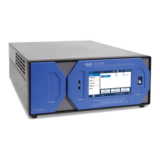
Teledyne T703 Operation Manual (241 pages)
PHOTOMETRIC O3 CALIBRATOR
Brand:
Teledyne
| Category:
Test Equipment
| Size: 6 MB
Table of Contents
About this Manual
7
Table of Contents
8
Introduction
17
T703/T703U Calibrator Overview
17
Options
18
Specifications and Approvals
19
Specifications
19
Table 2-1: T703/T703U System Specifications
19
Table 2-2: T703/T703U Specifications for Ozone Generator
19
Approvals and Certifications
20
Safety
20
Emc
20
Other Type Certifications
20
Table 2-3: T703/T703U Specifications for O
20
Getting Started
21
Unpacking and Initial Setup
21
Front, Rear, and Internal Calibrator Description
22
Figure 3-1: Front Panel Layout
22
Figure 3-2: Display Screen and Touch Control
23
Table 3-1: Display Screen and Touch Control Description
23
Figure 3-3: Display/Touch Control Screen Mapped to Menu Charts
24
Figure 3-4: Rear Panel Layout
25
Table 3-2. Rear Panel Description
25
Figure 3-5: T703 Internal Layout - Top View
26
Figure 3-6: T703 Pneumatic Diagram
27
Figure 3-7: T703U Internal Layout - Top View
28
Figure 3-8: T703U Pneumatic Diagram
29
Electrical Connections
30
Power Connection
30
Analog Output Test Channel Connections
30
Figure 3-9: TEST CHANNEL Connector
30
Connecting the Status Outputs
31
Figure 3-10: Status Output Connector
31
Table 3-3: Status Output Pin Assignments
31
Connecting the Control Inputs
32
Table 3-4: Control Input Pin Assignments
32
Figure 3-11: Digital Control Input Connectors
33
Connecting the Control Outputs
34
Figure 3-12: Digital Control Output Connector
34
Table 3-5: Control Output Pin Assignments
34
Communication Connections
35
And RS485 Connection
35
Ethernet Connection
35
Multidrop Network Connection
35
USB Option Connection
35
Pnenumatic Connections
36
Dry Air in
36
Zero Air in
36
Figure 3-13: Basic Pneumatic Setup
36
Output Manifold
37
Exhaust
37
Measuring an External Ozone Source
37
Initial Operation
37
Start-Up
37
Warm up
37
Warning Messages
38
Table 3-6: Possible Warning Messages at Start-Up
39
Functional Check
40
Bnch (Bench)
41
Cnst (Constant)
41
Generator
41
Generator Mode
41
Operating Modes for the O
41
Setting the O
41
Setting the Output Flow Rate
42
Calculating Output Flow Rate
42
Figure 3-14: Output Pressure Regulator Assembly
42
Output Flow Setup
42
Operating the Calibrator
43
Test Functions
44
Table 4-1: Test Functions Defined
44
Overview of Operating Modes
45
Figure 4-1: Front Panel Display
45
Table 4-2: Calibrator Operating Modes
45
Standby Mode
46
General Information about the GENERATE Mode
47
GENERATE > AUTO: Basic Generation of Calibration Gas
47
Automatic Calibration Sequences
47
SETUP > SEQ: Programming Calibration Sequences
48
Table 4-3: Automatic Calibration SEQUENCE Set up Attributes
48
Table 4-4: Calibration SEQUENCE Step Instruction
48
Activating a Sequence from the T703/T703U Front Panel
49
Naming a Sequence
50
Setting the Repeat Count for a Sequence
51
Using the Internal Clock to Trigger Sequences
52
Setting up Control Inputs for a Sequence
55
Setting up Control Outputs for a Sequence
56
Setting the Progress Reporting Mode for the Sequences
57
Table 4-5: Sequence Progress Reporting Mode
57
Adding Sequence Steps
58
Figure 9-14: O
59
The GENERATE Step
59
The DURATION Step
60
The STANDBY Step
60
The EXECSEQ Step
61
The CC OUTPUT Step
62
Deleting or Editing an Individual Step in a Sequence
63
Deleting a Sequence
64
Setup > Cfg
65
Setup > Clk
66
Setting the Internal Clock's Time and Day
66
Figure 9-15: O
66
Figure 9-16: O
66
Adjusting the Internal Clock's Speed
67
Setup > Pass
68
Table 4-6: Password Levels
68
SETUP > DIAG > TEST CHAN OUTPUT: Using the TEST Channel Analog Output
70
Configuring the TEST Channel Analog Output
70
Figure 4-2: TEST CHANNEL Connector
70
Table 4-7: DIAG - Analog I/O Functions
70
The Analog I/O Configuration Submenu
70
Selecting a TEST Channel Function to Output
72
Table 4-8: Test Channels Functions Available on the Analog Output
72
Table 4-9: Analog Output Voltage Range Min/Max
74
TEST Channel Voltage Range Configuration
74
Turning the TEST Channel Over-Range Feature ON/OFF
75
Adding a Recorder Offset to the TEST Channel
76
TEST Channel Calibration
77
Enabling or Disabling the TEST CHANNEL Auto-Cal Feature
78
Automatic TEST Channel Calibration
79
Figure 4-3: Setup for Calibrating the TEST CHANNEL
81
Manual Calibration of the TEST Channel Configured for Voltage Ranges
81
Table 4-10: Voltage Tolerances for the TEST CHANNEL Calibration
81
AIN Calibration
83
SETUP > more > VARS: Internal Variables (VARS)
84
Table 4-11: Variable Names (VARS)
84
Operating the Calibrator as an O
86
Set up for Operation as an O
86
Figure 4-4: Set up to Measure an External O Source
86
Photometer
86
SETUP > LVL: Setting up and Using LEADS (Dasibi) Operating Levels
88
General Information about LEADS LEVELS
88
Dot Commands
88
Levels
89
Activating an Existing LEVEL
89
Programming New LEVELS
90
Creating a Generate LEVEL
91
Editing or Deleting a LEVEL
92
Figure 4-5: LEADS Level Display Format
92
Configuring LEVEL Status Blocks
93
Communications
94
Using the Analyser's Communication Ports
94
DTE and DCE Communication
94
Serial COM Port Default Settings and Connector Pin Assignments
95
Figure 5-1: Default Pin Assignments for Rear Panel COM Port Connectors (RS-232 DCE & DTE)
95
Figure 5-2: CPU COM1 & COM2 Connector Pin-Outs for RS-232 Mode
96
COM Port Baud Rate
97
COM Port Communication Modes
97
Table 5-1: COM Port Communication Modes
98
COM Port Testing
100
Machine ID
101
Terminal Operating Modes
102
Help Commands in Terminal Mode
102
Table 5-2: Terminal Mode Software Commands
102
Command Syntax
103
Table 5-3: Teledyne API Serial I/O Command Types
103
Data Types
104
Status Reporting
104
COM Port Password Security
105
General Message Format
105
Remote Access by Modem
106
Multidrop RS-232 Set up
108
Figure 5-3: Jumper and Cables for Multidrop Mode
109
Configuration of COM2
110
Remote Access Via the USB Port (Option)
110
Figure 5-4: RS232-Multidrop PCA Host/Calibrator Interconnect Diagram
110
Remote Access Via the Ethernet
112
Table 5-4: Ethernet Status Indicators
112
Configuring the Ethernet Interface Using DHCP
113
Table 5-5: Lan/Internet Configuration Properties
113
Manually Configuring the Network IP Addresses
115
Changing the Calibrator's Hostname
117
APICOM Remote Control Program
118
Figure 5-5: APICOM Remote Control Program Interface
118
Calibration and Verification
119
Verifying/Calibrating the O Photometer
119
Setup for Verifying and Calibrating the O
119
Generator
120
Calibration Manifold Exhaust/Vent Line
121
Figure 6-2: Set up for Verifying Optional O Photometer Using an External O Generator
121
Calibrating the O3 Photometer
122
Verifying O 3 Photometer Performance
122
Photometer Zero Calibration
123
Photometer Span Calibration
124
O 3 Photometer Dark Calibration
125
O 3 Photometer Backpressure Compensation Calibration
126
Calibrating the Ogenerator
126
O 3 Generator Calibration Table
127
Viewing Ogenerator Calibration Points
128
Adding or Editing O
129
Deleting O Generator Calibration Points
130
Turning O Generator Calibration Points on / off
131
Performing an Automatic Calibration of the Ogenerator
132
Calibrating Gas Pressure Sensors
133
Figure 6-1: Set up for Verifying Optional O Figure 6-2: Set up for Verifying Optional O Figure 6-3: Pressure Calibration Monitor Point - T703
133
Gas Pressure Sensor Calibration Set up
133
Table 6-1: T703/T703U Pressure Sensors
133
Figure 6-4: Pressure Calibration Monitor Points - T703U
134
Figure 6-5: Pressure Regulator Monitor Connection Point (T703 and T703U)
134
Calibrating the Pressure Sensors
135
Figure 6-6: O 3 Regulator Pressure Monitor Point (T703U Only)
135
Gas Flow Calibration
136
Table 6-2: T703/T703U Gas Pressure to Output Flow Conversion Table
137
Calibrating the Photometer's Sample Gas Flow
138
Calibrating the Output Gas Flow
139
Figure 6-7: Output Flow Calibration Monitor Point - T703
139
Output Gas Flow Set up
139
Performing an Output Gas Flow Calibration
140
Maintenance Schedule & Procedures
141
Maintenance Schedule
141
Table 7-1: T703 Maintenance Schedule
143
Performing Leak Checks
145
Pressure Leak Check
145
Figure 7-1: T703 Pneumatic Setup for Performing Pressure Leak Checks
146
Figure 7-2: T703U Pneumatic Setup for Performing Pressure Leak Checks
146
Cleaning or Replacing the Absorption Tube
147
Rebuilding the Dry Air Pump
147
Photometer UV Source Lamp Adjustment
148
Photometer UV Source Lamp Replacement
150
Figure 7-3: Photometer - Location of UV Detector Gain Adjustment & UV Lamp Set Screw
150
Adjustment or Replacement of Ozone Generator UV Lamp
151
Figure 7-4: O 3 Generator Temperature Thermistor and DC Heater Locations
151
Generator Temperature Thermistor and DC Heater Locations
151
General Troubleshooting & Service
153
General Troubleshooting
153
Fault Diagnosis with WARNING Messages
154
Table 8-1: Front Panel Warning Messages
156
Fault Diagnosis with Test Functions
157
Table 8-2: Test Functions - Indicated Failures
157
Using the Diagnostic Signal I/O Function
158
Figure 8-1: Example of Signal I/O Function
159
Using the Analog Output Test Channel
160
Table 8-3: Test Channel Outputs as Diagnostic Tools
160
Using the Internal Electronic Status Leds
161
CPU Status Indicator
161
Relay PCA Status Leds
161
C Bus Watchdog Status Leds
161
Figure 8-2: CPU Status Indicator
161
Table 8-4: Relay PCA Watchdog LED Failure Indications
161
Figure 8-3: Relay PCA Status Leds Used for Troubleshooting
162
Table 8-5: Relay PCA Status LED Failure Indications
162
Troubleshooting with Relay Board Status Leds
162
Subsystem Checkout
163
Verify Subsystem Calibration
163
AC Main Power
163
DC Power Supply
163
Figure 8-4: Location of DC Power Test Points on Relay PCA
164
Table 8-6: DC Power Test Point and Wiring Color Codes
164
Table 8-7: DC Power Supply Acceptable Levels
164
I 2 C Bus
165
Touchscreen Interface
165
LCD Display Module
165
Relay PCA
165
Photometer Ogenerator Pressure /Flow Sensor Assembly
166
Table 8-8: Relay PCA Control Devices
166
Motherboard
168
A/D Functions
168
Test Channel / Analog Outputs Voltage
169
Status Outputs
170
Table 8-10: Status Outputs Check
170
Table 8-9: Analog Output Test Function - Nominal Values Voltage Outputs
170
Control Inputs
171
Control Outputs
171
Table 8-11: T703 Control Input Pin Assignments and Corresponding Signal I/O Functions
171
Table 8-12: Control Outputs Pin Assignments and Corresponding Signal I/O Functions Check
171
Cpu
172
Communications
172
General RS-232 Troubleshooting
172
Troubleshooting Calibrator/Modem or Terminal Operation
173
Temperature Problems
173
Box / Chassis Temperature
173
Photometer Sample Chamber Temperature
173
Ozone Generator Temperature
174
UV Lamp Temperature
174
Troubleshooting the Ophotometer
174
Dynamic Problems with the O
174
Photometer
174
Noisy or Unstable O Readings at Zero
175
Noisy, Unstable, or Non-Linear Span O Readings
175
Slow Response to Changes in Concentration
175
The Analog Output Signal Level Does Not Agree with Front Panel Readings
175
Cannot Span
176
Cannot Zero
176
Checking Measure / Reference Valve
176
Trouble Shooting the Ogenerator
176
Troubleshooting the Ogenerator in the T703
177
Troubleshooting the Ogenerator in the T703U
177
Repair Procedures
178
Repairing Sample Flow Control Assembly
178
Figure 8-5: Critical Flow Restrictor Assembly Disassembly
178
Disk-On-Module Replacement Procedure
179
Faq's
180
Technical Assistance
180
Principles of Operation
181
Pneumatic Operation
181
Gas Flow Control
181
Photometer Critical Flow Orifice
182
Internal Gas Pressure Sensors
182
Electronic Operation
183
Overview
183
Figure 9-3: Electronic Block Diagram
183
Central Processing Unit (CPU)
184
Figure 9-4: CPU Board Annotated
184
Disk on Module (DOM)
185
Flash Chip
185
Relay PCA
185
Figure 9-5: Relay Board PCA with AC Relay Retainer Removed
186
Valve Control
186
Figure 9-6: Heater Control Loop Block Diagram
187
Figure 9-7: Status LED Locations - Relay PCA
187
Heater Control
187
Relay PCA Status Leds and Watch Dog Circuitry
187
Relay PCA Watchdog Indicator (D1)
188
Table 9-1: Relay Board Status Leds
188
Motherboard
189
A to D Conversion
189
Analog Outputs
189
Sensor Inputs
189
Thermistor Interface
189
External Digital I/O
190
I 2 C Data Bus
190
Power-Up Circuit
190
Power Supply and Circuit Breaker
190
AC Power Configuration
192
Figure 9-8: Power Distribution Block Diagram
192
AC Configuration - Internal Pump (JP7)
193
Figure 9-9: Location of the AC Configuration Jumper for the Dry Air Pump
193
Table 9-2: AC Power Configuration for Internal Pumps (JP7)
193
Front Panel Touchscreen/Display Interface
194
Figure 9-10: Pump AC Power Jumpers (JP7)
194
Front Panel Interface PCA
195
Software Operation
195
Figure 9-11: Front Panel Layout
195
Ogenerator Operation
196
Principle of Photolytic O
196
Figure 9-12: Schematic of Basic Software Operation
196
Generation
196
Figure 9-13: O
197
Generator Pneumatic Operation
198
O 3 Generator Electronic Operation
198
O 3 Generator Temperature Control
200
Photometer Operation
200
Measurement Method
200
Calculating O Concentration
200
Figure 9-17: O
200
Table 9-3: Photometer Measurement / Reference Cycle
202
The Measurement / Reference Cycle
202
Figure 9-18: T703 O
203
Figure 9-19: T703 O Photometer Gas Flow - Reference Cycle
203
Photometer Gas Flow - Measure Cycle
203
The Absorption Path
204
Figure 9-20: T703U O3 Photometer Gas Flow - Measure Cycle
204
Figure 9-21: T703U O
204
Photometer Gas Flow - Reference Cycle
204
Interferent Rejection
205
Photometer Layout
205
Figure 9-22: O
205
Photometer Absorption Path
205
Photometer Pneumatic Operation
206
Photometer Layout - Top Cover Removed
206
Photometer Electronic Operation
207
O 3 Photometer Temperature Control
207
Photometer Electronic Block Diagram
207
Pneumatic Sensors for the O Photometer
208
Main Menu
217
Figure 9-23: O
223
Figure 9-24: O
223
Advertisement
Teledyne T703 Training Manual (96 pages)
PHOTOMETRIC OZONE CALIBRATOR
Brand:
Teledyne
| Category:
Test Equipment
| Size: 3 MB
Table of Contents
Table of Contents
3
Principle of Operation
5
Principle of Photolytic O
7
Generator Pneumatic Operation
8
Ogenerator Electronic Operation
8
O 3 Generator Temperature Control
10
Photometer Operation
12
Measurement Method
12
The Measurement / Reference Cycle
13
The Absorption Path
15
Photometer Layout
17
Photometer Pneumatic Operation
17
Photometer Electronic Operation
18
Relay Pca
18
O 3 Photometer Temperature Control
19
Pneumatic Sensors for the O
19
User Notes
20
Pneumatic Diagram
23
Menu Structure
27
Quick Calibration
37
Analog Calibration
39
Bench Calibration
40
Maintenance
43
Leak Checking
49
Performing Leak Checks
51
Pressure Leak Check
51
Specifications
55
Warnings and Test Functions
61
Test Function
65
Layout
69
Other Options
75
T Series Addendum
82
Printed Copies Are Uncontrolled
82
Getting Started
83
Front Panel
83
Front Panel Interface PCA
87
Rear Panel
88
Analog Input Calibration
90
AIN Calibration
91
USB Configuration
92
Troubleshooting Faults
94
LCD Display Module
94
Diagrams and Schematics
95
Advertisement
Related Products
Teledyne T700
Teledyne T703U
Teledyne T700U
Teledyne T750
Teledyne T750U
Teledyne T3DSO2102
Teledyne T3HVD1500-200
Teledyne T3DSO2354HD
Teledyne T3DSO2104HD
Teledyne T3AWG6K Series
Teledyne Categories
Measuring Instruments
Analytical Instruments
Test Equipment
Digital Camera
Laboratory Equipment
More Teledyne Manuals
Login
Sign In
OR
Sign in with Facebook
Sign in with Google
Upload manual
Upload from disk
Upload from URL