Sign In
Upload
Manuals
Brands
Teledyne Manuals
Test Equipment
T750
Teledyne T750 Manuals
Manuals and User Guides for Teledyne T750. We have
1
Teledyne T750 manual available for free PDF download: User Manual
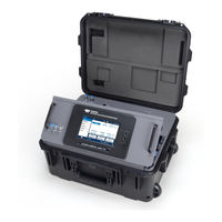
Teledyne T750 User Manual (186 pages)
Portable Calibrators
Brand:
Teledyne
| Category:
Test Equipment
| Size: 10.88 MB
Table of Contents
Table of Contents
9
Introduction
17
T750 Specifications
18
Table 1-1. T750 System Specifications
18
T750U Specifications
19
Table 1-2. T750 Options Specifications
19
Table 1-3. T750U System Specifications
19
Compliance and Certifications
20
Table 1-4. T750U GPT and Option Specifications
20
Getting Started
21
Unpacking
21
Ventilation and Clearance
22
Instrument Layout
22
Input and Control Panel
22
Figure 2-1. Control/Display and Input Panel (Shown with Model T750 Label)
22
Figure 2-2. Display Screen and Touch Control
23
Communications and Output Panel
24
Figure 2-3. Communications and Output Panel
24
Table 2-2. Communications and Output Panel Description
24
Internal Layout
25
Figure 2-4. Internal Layout (Components Labeled "Option" Are Standard in T750U)
25
Connections and Startup
26
Electrical Connections
26
Power Connection
26
Connecting the Analog Output Channel
27
Connecting the Status Outputs (Digital Outputs)
27
Figure 2-5. Analog Output Connector
27
Figure 2-6. Status Output Connector
27
Connecting the Control Inputs (Digital Inputs)
28
Table 2-3. Status Output Pin Assignments
28
Table 2-4. Control Input Pin Assignments
28
Figure 2-7. Digital Control Input Connectors
29
Connecting the Control Outputs (Digital Outputs)
30
Connecting the Communication Interfaces
30
Figure 2-8. Digital Control Output Connector
30
Table 2-5. Control Output Pin Assignments
30
Figure 2-9. Connector Pin-Outs for RS-232 Mode
31
Figure 2-10. Jumper and Cables for Multidrop Mode
34
Figure 2-11. RS-232-Multidrop PCA Host/Calibrator Interconnect Diagram
35
Pneumatic Connections
36
About Diluent Gas (Zero Air)
36
About Calibration Gas
36
Connecting Diluent Gas to the Calibrator
37
Connecting Calibration Source Gas to the Calibrator
37
Connecting Gas Outputs from the Calibrator
38
Figure 2-12. Set up for T750 - Connecting the Basic T750 to a Sample Manifold
38
Figure 2-13. Connections to a Sample Gas Manifold
39
Figure 2-14. Connections to Calibration Manifold
40
Figure 2-15. Connections to a Dual Span Gas / Zero Air Manifold
41
Pneumatic Flow Diagrams
42
Figure 2-16. T750 Pneumatic Diagram - Base Unit
42
Flow Diagrams with Other Pneumatic Connections
43
Figure 2-17. T750 Pneumatics with Optional O
43
Table 2-6. Valve States for T750 Calibrator with Optional O Generator
44
Figure 2-18. Flow with O
45
Table 2-7. Valve States with Optional O Generator and Photometer (Options in T750)
46
Figure 2-19. Basic T750 with Multiple Calibration Gas Mfcs
47
Figure 2-20. Flow with Multiple Cal Gas Mfcs and O Generator and Photometer (Options in T750)
48
Startup, Functional Checks, and Initial Calibration
49
Figure 2-21. Status Screens at Startup
49
Figure 2-22. Initial Home Page (in Standby Mode, Prior to Gas Setup)
49
Alerts: Warnings and Other Messages
50
Functional Checks
50
Figure 2-23. Viewing Active Alerts Page
50
Calibration Gas Setup
51
Selecting an Operating Mode for the O Generator
52
Gas Flow Rate Setup
52
Start Generating
53
Figure 2-24. Basic Generate Initiation
53
Configuration
55
Menu Overview
55
Table 3-1. Menu Overview
55
Main Menu
58
Home
58
Figure 3-1. User Interface Orientation
58
Dashboard
59
Figure 3-2. Dashboard Page
59
Figure 3-3. Viewing a Live Plot from Dashboard Page
59
Alerts
60
Figure 3-4. Navigating to the Active Alerts Page
60
Generate
61
Utilities
61
Datalog View
61
Figure 3-5. Active Alerts Cleared
61
Figure 3-6. Generate Menu (GPT Buttons Available with O Generator Option)
61
Alerts Log
62
USB Utilities (Downloads and Updates)
62
Figure 3-7. USB Utilities Pages
62
Figure 3-8. das Download Page
63
Figure 3-9. Configuration Transfer
63
Diagnostics
64
Setup (Configuring the Calibrator's Features/Functions)
64
Setup>Data Logging
65
Figure 3-10. Setup>Data Logging Page
65
Figure 3-11. Datalog Configuration, New Log Page
65
Creating a User-Defined Data Log
66
Figure 3-12. Datalog Configuration
66
Configuring Trigger Types for the Datalogger
67
Figure 3-13. Datalog Periodic Trigger Configuration
67
Figure 3-14. Datalog - Conditional Trigger Configuration
67
Setup>Events
68
Figure 3-15. Events List
68
Creating User-Defined Events
69
Editing or Deleting Events
69
Figure 3-16. Event Configuration
69
Figure 3-17. Existing Event for Viewing or Editing
69
Setup>Dashboard
70
Figure 3-18. Dashboard Configuration Page through Setup Menu
70
Figure 3-19. Dashboard Configuration Page through Dashboard Shortcut
70
Setup>Vars (Variables)
71
Setup>Homescreen
71
Figure 3-20. Vars Configuration Page
71
Figure 3-21. Home Configuration through Setup>Homescreen Menu
71
Setup>Digital Outputs (Status)
72
Setup>Sequences
72
Figure 3-22. Digital Status Outputs Setup
72
Figure 3-23. Example List of Configured Sequences
73
Figure 3-24. Configuring a Sequence
73
Table 3-2. Automatic Calibration Sequence Set up Attributes
74
Setting up Control Inputs for a Sequence
75
Figure 3-25. Sequence CC Inputs Setup Page
75
Setting up Control Outputs for a Sequence
76
Activating, Editing, Deleting Sequences
76
Figure 3-26. Sequence CC Outputs Setup Page
76
Setup>Levels
77
Editing/Deleting Levels
78
Activating Levels
78
Figure 3-27. Levels Programming and Editing
78
Setup>Analog Outputs
79
Figure 3-28. Analog Output Configuration
79
Analog Output Voltage Range Configuration
80
Adding a Recorder Offset to the Analog Output
80
Calibrating the Analog Output
80
Figure 3-29. Analog Output Auto Calibration Page
80
Table 3-3. Analog Output Voltage Range Min/Max
80
Figure 3-30. Setup for Manually Calibrating the Analog Output
81
Figure 3-31. Analog Output Manual Calibration Page
81
Table 3-4. Voltage Tolerances for the Analog Output Calibration
81
Setup>Instrument
82
Setup>Comm (Communications)
82
Com1/Com2
82
Figure 3-32. Setup>Instrument Menu
82
Table 3-5. COM1/COM2 Configuration
82
TCP Port1
83
TCP Port2
83
Network Settings
83
Setup>Gas
84
Figure 3-33. Communications Configuration, Network Settings
84
Table 3-6. Lan/Ethernet Configuration Properties
84
Operation
85
Standby Mode
85
Table 4-1. Status of Internal Pneumatics During Standby Mode
85
Generate Mode
86
Figure 4-1. Gas Flow through T750 with O
86
Figure 4-2. Generate Menu
86
Figure 4-3. Gas Flow through Basic T750 in GENERATE Mode
87
Table 4-2. Status of Internal Pneumatics During GENERATE Mode
87
Figure 4-4. Gas Flow through T750 with O
88
Figure 4-5. Gas Flow through T750 with O
88
Generate>Auto
89
Generate>Manual
89
Figure 4-6. Generate>Auto Page
89
Figure 4-7. Generate>Manual Page
89
Determining the Source Gas Flow Rate
90
Determining the Diluent Gas Flow Rate
90
Generate>Gptz, GPTPS, GPT: Understanding Gas Phase Titration (GPT)
91
Determining the Diluent Gas Flow Rate with O Generator Option
91
Meeting USEPA Guidelines for GPT Calibration
91
GPT Theory
92
Choosing an Input Concentration for the no
92
Determining the Total Flow for GPT Calibration Mixtures
93
Generate>Gptz: Generating GPT Flow Conditions
93
Gpt)
93
Table 4-3. Status of Internal Pneumatics During GENERATE GPTZ Mode
93
Figure 4-8. Gas Flow through T750 with O
94
Figure 4-9. Sample Generate GPTZ Page
94
Generate>Gptps: Performing a GPT Pre-Set (to be Run after GPTZ and Prior to GPT)
95
Table 4-4. Status of Internal Pneumatics During GENERATE GPTPS Mode
95
Figure 4-10. Gas Flow through T750 with O
96
Figure 4-11. Sample Generate GPTPS Page
96
Generate>Gpt: Performing a Gas Phase Titration Calibration
97
Figure 4-12. Gas Flow through T750 with O
97
Table 4-5. Status of Internal Pneumatics During GENERATE GPT Mode
97
Generate>Sequence: Automatic Operation Using Sequences
98
Activating a Sequence from the Touchscreen
98
Activating a Sequence with the Internal Timer
98
Figure 4-13. Sample Generate GPT Page
98
Activating a Sequence with the External Digital Control Inputs
99
Activating a Sequence or Defaulting to Control Other Devices
99
Activating a Sequence as a Subprocess in Another Sequence
99
Activating a Sequence through a Communications Interface
99
Generate>Level: Automatic Operation Using LEADS Levels
99
Activating Levels
100
Communications and Remote Operation
101
Using the Communication Ports
101
Data Terminal / Communication Equipment (DTE, DCE)
101
Modes, Baud Rate and Serial Communication
101
Serial Communication: RS-232
102
Serial Communication: RS-485 (Option)
102
Ethernet
102
Numaview™ Remote
102
Table 5-1. Ethernet Status Indicators
102
MODBUS Protocol and Com Port Configuration
103
Calibration and Verification
105
Verifying and Calibrating the Mfcs
105
Figure 6-1. MFC Config Page
105
Setup for Verifying and Calibrating the Mfcs
106
Verifying and Calibrating the Mfcs
106
Table 6-1. Examples of MFC Calibration Points
106
Verifying and Calibrating the O Photometer (Option in T750)
107
Figure 6-2. MFC Calibration
107
Setup and Verification of O Photometer Performance
108
Figure 6-3. Set up for Verifying O
108
Photometer
108
Setup and Calibration of O Photometer
109
Figure 6-4. O 3 Photometer Performance Verification
109
Figure 6-5. External Photometer Calibration Setup with Direct Connections
110
Figure 6-6. External Photometer Calibration Setup with Calibration Manifolds
111
Photometer Zero Calibration
112
Photometer Span Calibration
112
Figure 6-7. O 3 Photometer Bench Cal Page
112
O 3 Photometer (Option in T750) Gas Flow Calibration
113
Figure 6-8. Photometer Flow Calibration Page
113
O 3 Photometer Backpressure Compensation Calibration
114
Figure 6-9. Back Pressure Compensation
114
Calibrating the O
115
Generator (Option in T750)
115
Figure 6-10. O 3 Generator Calibration Setup
115
Calibrating Gas Pressure Sensors
116
Pressure Sensor Setup
116
Table 6-2. Pressure Sensor Calibration Setup
116
Figure 6-11. Pressure Monitor Points, T750 Basic Unit
117
Figure 6-12. Pressure Monitor Points, T750 with O3 Options and Multiple Cal Mfcs Installed
117
Calibrating the Diluent, Cal Gas, and O Generator Option Pressure Sensors
118
Calibrating the O 3 Photometer Option Pressure Sensor
118
Figure 6-13. PSIG Pressure Ca
118
Analog Inputs Calibration
119
Figure 6-14. In-Hg Pressure Cal for O Photometer Option
119
Figure 6-15. Analog Inputs Calibration Page
119
Maintenance and Service
121
Maintenance Schedule
121
Table 7-1. Maintenance Schedule
123
Operational Health Checks
125
Software/Firmware Updates
125
Remote Updates
125
Figure 7-1. Report Generation Page
125
Figure 7-2. Remote Update Page
125
Manual Reload/Update Procedures
126
Performing the Auto Leak Check
126
Leak Check Equipment and Calibrator Setup
126
Figure 7-3. Manual Update Page (and Other Utilities)
126
Figure 7-4. Clamping the Photometer Sensor Input and Pump Output
127
Figure 7-5. Internal Vent Location
128
Figure 7-6. Gas Flow for Auto-Leak Check Procedure of Base Model T750 (no Photometer)
128
Returning the Calibrator to Service after Auto Leak Check
129
Figure 7-7. Gas Flow for Auto-Leak Check Procedure of Calibrator with Photometer
129
Cleaning or Replacing the Absorption Tube
130
Adjusting the Photometer Option's UV Source Lamp
131
Figure 7-8. Photometer - Location of UV Detector Gain Adjustment & UV Lamp Set Screw
131
Replacing the Photometer Option Suv Source Lamp
132
Adjusting or Replacing the Ozone Generator UV Lamp
133
Figure 7-9. O 3 Generator UV Lamp Assembly
133
General Troubleshooting & Service
135
General Troubleshooting
135
Fault Diagnosis with Messages in the Alerts Page
136
Table 8-1. Possible Alerts
136
Fault Diagnosis with Dashboard Functions
137
Table 8-2. Dashboard Functions (Tags) - Indicated Failures
137
Using the Diagnostic Analog Inputs Function
138
Using the Signal Outputs for Diagnostics
139
Table 8-3. Signal Outputs as Diagnostic Tools
139
Using the Internal Electronic Status Leds
140
CPU Status Indicator
140
Power Distribution Board Status Leds
140
C Bus Watchdog Status Leds
140
Figure 8-1. CPU Status Indicator
140
Table 8-4. Power Distribution Board Watchdog LED Failure Indications
140
Troubleshooting with Power Distribution Board Status Leds
141
Figure 8-2. Power Distribution Board Status Leds Used for Troubleshooting
141
Table 8-5. Power Distribution Board Status LED Failure Indications
141
Subsystem Checkout
142
Verify Subsystem Calibration
142
AC Main Power
142
DC Power Supply
142
Figure 8-3. Location of DC Power Test Points on Power Distribution Board
143
Table 8-6. DC Power Test Point and Wiring Color Codes
143
I 2 C Bus
144
Touchscreen Interface
144
Table 8-7. DC Power Supply Acceptable Levels
144
Power Distribution Board
145
Input Gas Pressure/Flow Sensor Assembly
145
Table 8-8. Power Distribution Board Control Devices
145
Photometer O 3 Generator Pressure /Flow Sensor Assembly
146
Motherboard
147
A/D Functions
147
Analog Outputs Voltage
147
Figure 8-4. Analog Outputs Page
147
Status Outputs (Digital Output Pins 1 - 8)
148
Digital Control Inputs
148
Table 8-9. Analog Output Test Function - Nominal Values Voltage Outputs
148
Table 8-10. Digital Control Input Pin Assignments and Corresponding Functions
148
Control Outputs (Digital Output Pins 1 - 12)
149
Cpu
149
Communications, General Troubleshooting
150
Temperature Problems
150
Box / Chassis Temperature
150
Photometer Sample Chamber Temperature
150
UV Lamp Temperature
150
Ozone Generator Temperature
151
Troubleshooting the O Photometer
151
Dynamic Problems with the O Photometer
151
Noisy or Unstable O Readings at Zero
152
Noisy, Unstable, or Non-Linear Span O
152
Slow Response to Changes in Concentration
152
Readings
152
The Analog Output Signal Level Does Not Agree with Display Readings
152
Cannot Zero
152
Cannot Span
153
Checking Measure / Reference Valve
153
Troubleshooting the O Generator
154
Service Procedures
154
Disk-On-Module Replacement Procedure
154
Technical Assistance
155
Principles of Operation
157
Basic Principles of Dynamic Dilution Calibration
157
Gas Phase Titration Mixtures for Oand no
158
Pneumatic Operation
159
Gas Flow Control
159
Diluent and Source Gas Flow Control
159
Flow Control Assemblies for O Components
160
Critical Flow Orifices
160
Internal Gas Pressure Sensors
161
Electronic Operation
162
Overview
162
Figure 9-1. Electronic Block Diagram
162
Central Processing Unit (CPU)
164
Disk on Module (DOM)
164
Flash Chip
164
Figure 9-2. CPU Board Annotated
164
Power Distribution Board (Relay PCA)
165
Figure 9-3. Power Distribution Board (Relay PCA)
165
Valve Control
166
Figure 9-4. Relay PCA Location
166
Heater Control
167
Power Distribution Board Status Leds and Watch Dog Circuitry
167
Figure 9-5. Heater Control Loop Block Diagram
167
Figure 9-6. Status LED Locations - Power Distribution Board
167
Watchdog Indicator (D1)
168
Motherboard
168
Power Supply and Circuit Breaker
169
Figure 9-7. Power Distribution Block Diagram
169
Input and Control Panel Touchscreen/Display Interface
170
Input and Control Panel Interface PCA
170
Figure 9-8. Input and Control Panel Layout
170
Software Operation
171
Figure 9-9. Schematic of Basic Software Operation
171
O 3 Generator Operation
172
Principle of Photolytic O
172
Generation
172
Figure 9-10. O 3 Generator Internal Pneumatics
172
O 3 Generator Pneumatic Operation
173
Figure 9-11. O 3 Generator Valve and Gas Fixture Locations
173
O 3 Generator Electronic Operation
174
Figure 9-12. O 3 Generator Electronic Block Diagram
174
Figure 9-13. O 3 Generator Electronic Components Location
174
O 3 Generator Temperature Control
175
O 3 Generator Pneumatic Sensor
175
Photometer Operation
175
Figure 9-14. O 3 Generator Temperature Thermistor and DC Heater Locations
175
Measurement Method
176
Calculating O 3 Concentration
176
The Measurement / Reference Cycle
177
Figure 9-15. O 3 Photometer Gas Flow - Measure Cycle
178
Figure 9-16. O 3 Photometer Gas Flow - Reference Cycle
178
The Absorption Path
179
Interferent Rejection
179
Figure 9-17. O 3 Photometer Absorption Path
179
Photometer Layout
180
Photometer Pneumatic Operation
180
Figure 9-18. O 3 Photometer Layout - Top Cover Removed
180
Photometer Electronic Operation
181
Figure 9-19. O Photometer Electronic Block Diagram
181
O 3 Photometer Temperature Control
182
Pneumatic Sensors for the O 3 Photometer
182
Advertisement
Advertisement
Related Products
Teledyne T700
Teledyne T703
Teledyne T703U
Teledyne T700U
Teledyne T750U
Teledyne LeCroy T3DSO2204A
Teledyne T3DSO2202
Teledyne T3DSO1102
Teledyne T3DSO1104
Teledyne T3DSO3000
Teledyne Categories
Measuring Instruments
Analytical Instruments
Digital Camera
Test Equipment
Laboratory Equipment
More Teledyne Manuals
Login
Sign In
OR
Sign in with Facebook
Sign in with Google
Upload manual
Upload from disk
Upload from URL