Sign In
Upload
Manuals
Brands
Allen-Bradley Manuals
Servo Drives
2198-D057-ERS4
Allen-Bradley 2198-D057-ERS4 Manuals
Manuals and User Guides for Allen-Bradley 2198-D057-ERS4. We have
2
Allen-Bradley 2198-D057-ERS4 manuals available for free PDF download: User Manual, Original Instructions
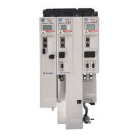
Allen-Bradley 2198-D057-ERS4 User Manual (460 pages)
Brand:
Allen-Bradley
| Category:
Servo Drives
| Size: 65.31 MB
Table of Contents
Table of Contents
3
Preface
11
Summary of Changes
11
Conventions Used in this Manual
12
Access the Attachments
13
Additional Resources
13
Start
15
Chapter 1 Kinetix 5700 Servo Drives Series Change
16
About the Kinetix 5700 Servo Drive System
17
DC-Bus Power Supply Input Power Configurations
19
Typical DC-Bus Power Supply Configuration Example
19
Multiple DC-Bus Power Supply Configuration Example
20
Extended DC-Bus Configuration Example
21
Itrak Power Supply Configuration Example
22
Regenerative Bus Supply Input Power Configurations
23
Typical Regenerative Bus Configuration Examples
23
Extended Regenerative Bus Configuration Example
26
Itrak Power Supply Configuration Example
27
8720MC-RPS Power Supply Input Power Configuration
28
Motor and Auxiliary Feedback Configurations
29
Typical Communication Configurations
30
Linear Topology
30
Ring Topology
31
Star Topology
32
Functional Safety Configurations
33
Hardwired Configuration
33
Integrated Safety Configurations
34
Safe Stop and Safe Monitor Configurations
36
Catalog Number Explanation
37
Agency Compliance
39
Chapter 2 System Design Guidelines
41
System Mounting Requirements
41
DC-Bus Voltage Regulation
42
AC Line Filter Selection
44
AC Line Impedance Considerations
45
Circuit Breaker/Fuse Selection
48
24V Control Power Evaluation
49
Contactor Selection
50
Passive Shunt Considerations
51
Active Shunt Considerations
52
Enclosure Selection
54
Minimum Clearance Requirements
56
Multi-Axis Shared DC-Bus Configurations
57
Accessory Module Selection
59
DC-Bus Power Supply Systems
59
Regenerative Bus Supply Systems
61
8720MC-RPS or Other Regenerative Power Supply
64
Accessory Module Flowcharts
65
Electrical Noise Reduction
67
Bonding Modules
67
Bonding Multiple Subpanels
69
Establishing Noise Zones
70
Cable Categories for Kinetix 5700 Systems
72
Noise Reduction Guidelines for Drive System Accessories
73
Determine Mounting Order
80
Plan the Kinetix 5700 Drive System Installation
41
Chapter 3
83
Mount Accessory Modules
83
Zero-Stack Tab and Cutout
84
Install Shared-Bus Connection Systems
84
DC-Bus Connection System
84
24V Input Power Connection System
85
Drill-Hole Patterns
87
Drill-Hole Pattern Calculations
88
Drill-Hole Patterns by Using the System Mounting Toolkit
90
Mount Your Kinetix 5700 Drive Modules
90
Kinetix 5700 Connector Data
94
Chapter 4
102
Safe Torque-Off Connector Pinout
102
Input Power Connector Pinouts
102
DC Bus and Shunt Resistor Connector Pinouts
103
Digital Inputs Connector Pinouts
103
Ethernet Communication Connector Pinout
105
Motor Power, Brake, and Feedback Connector Pinouts
105
Motor Feedback Connector Pinouts
106
Universal Feedback Connector Pinouts
107
Accessory Module Pinouts
107
Understand Control Signal Specifications
108
Digital Inputs
108
Ethernet Communication Specifications
109
Contactor Enable Relay
110
Converter OK Relay
111
Motor Brake Circuit
111
Control Power
113
Feedback Specifications
114
DSL Feedback Connector
114
Encoder Feedback Supported on the UFB Feedback Connector
114
Auxiliary Feedback Specifications
121
Encoder Phasing Definitions
123
Absolute Position Feature
124
Functional Safety Features
125
Hardwired STO Mode
125
Integrated Mode
125
Connect the Kinetix 5700 Drive System
127
Chapter 5 Basic Wiring Requirements
128
Routing the Power and Signal Cables
128
Input Power Configurations for Kinetix 5700 Power Supplies
129
DC-Bus Power Supply
129
Regenerative Bus Supply
132
Ground Screw/Jumper Settings
135
Kinetix 5700 Drive System Power Supply
135
Kinetix 5700 Inverters
136
Kinetix 5700 Itrak Power Supply
137
Remove/Install the Ground Screw/Jumper
137
Ground the Drive System
139
Ground the System Subpanel
139
Ground Multiple Subpanels
140
Wiring Requirements
141
Wiring Guidelines
145
Wire the Power Connectors
145
Wire the 24V Control Power Input Connector
145
Wire the Input Power Connector
147
Wire the Contactor Enable Connector
148
Wire the Digital Input Connectors
149
2198-XXXX-ERS3 (Series A) Connector Plugs
149
Connector Plugs
150
Wire the Safe Torque-Off Connector
150
Wire the Digital Inputs Connector
151
Wire Motor Power and Brake Connectors
152
Maximum Cable Lengths
155
Wiring Single Cables
159
Motor Feedback Connections
160
Apply the Single Motor Cable Shield Clamp
161
Wiring Power/Brake and Feedback Cables
163
Motor Power and Brake Cables
163
Motor Power/Brake Cable Series Change
164
Dual-Axis Inverter Power/Brake Cable Installation
165
Single-Axis Inverter Power/Brake Cable Installation
168
Motor Feedback Connections
172
Customer-Supplied Motor Power Cables
178
Accessory Module Connections
181
External Passive-Shunt Connections
182
External Active-Shunt Connections
183
DC-Bus Power Supply Active Shunt Connections
183
Regenerative Bus Supply Active Shunt Connections
183
Wire the External DC-Bus Connections
184
Bulletin VPC Motors and the Extended Speed Feature
185
Considerations for Powerohm Shunt Installation
185
Ethernet Cable Connections
186
Configure and Start the Kinetix 5700 Drive System
187
Chapter 6 Understand the Kinetix 5700 Display
188
Menu Screens
189
Setup Screens
192
Startup Sequence
197
Configure the Drive
198
Set the Network Parameters
198
Studio 5000 Logix Designer
198
Version History
198
Install the Kinetix 5700 Add-On Profile
199
Configure the Logix 5000 Controller
200
Configure the Kinetix 5700 Drive Modules
203
Configure the DC-Bus Power Supply
203
Configure the Regenerative Bus Supply
207
Configure the Inverter Drives
211
Continue Inverter Configuration
219
Configure the Motion Group
223
Configure Regenerative Bus Supply Axis Properties
224
Configure Vertical Load Control Axis Properties
229
Configure Feedback-Only Axis Properties
230
Configure Induction-Motor Frequency-Control Axis Properties
232
General and Motor Categories
232
Basic Volts/Hertz Method
234
Sensorless Vector Method
236
Fan/Pump Volts/Hertz Method
239
Configure IPM Motor Closed-Loop Control Axis Properties
241
Configure SPM Motor Closed-Loop Control Axis Properties
245
Configure Induction-Motor Closed-Loop Control Axis Properties
249
Configure Feedback Properties
256
Configure Module Properties
256
Configure Axis Properties
258
Download the Program
261
Apply Power to the Kinetix 5700 Drive System
262
Understand Bus-Sharing Group Configuration
263
Bus-Sharing Group Example
263
Configure Bus-Sharing Groups
265
Test and Tune the Axes
266
Test the Axes
267
Tune the Axes
269
Safety Precautions
275
Chapter 7 Interpret Status Indicators
276
Display Interface
276
Fault Code Overview
276
Fault Codes
277
SAFE FLT Fault Codes
277
Kinetix 5700 Status Indicators
278
Kinetix 5700 Accessory Module Status Indicators
279
Axis Troubleshooting
280
Regenerative Bus Supply Troubleshooting
281
Logix 5000 Controller and Drive Module Behavior
283
DC-Bus Power Supply Behavior
284
Regenerative Bus Supply Behavior
286
Itrak Power Supply Behavior
288
Inverter Behavior
289
Before You Begin
295
Chapter 8 Remove and Replace Kinetix 5700 Drive Modules
296
Remove Power and All Connections
296
Remove the Drive Module
300
Replace the Drive Module
301
Start and Configure the Drive Module
302
Series B Drives
302
Overview
305
Chapter 9
306
Certification
306
Average Frequency of a Dangerous Failure
307
Safe Torque-Off Feature
307
Out of Box State
308
Safe Torque-Off Status
311
Explicit Messages
312
Hardwired Safe Torque-Off
314
Compatible Controllers
314
Description of Operation
314
Troubleshoot the Safe Torque-Off Function
316
Safe Torque-Off Connector Data
317
Wire the Safe Torque-Off Circuit
318
Safe Torque-Off Wiring Requirements
320
Safe Torque-Off Feature Bypass
321
Cascade the Safe Torque-Off Signal
321
Hardwired Safe Torque-Off Electrical Specifications
323
Integrated Safe Torque-Off
323
Compatible Safety Controllers
324
Safety Application Requirements
324
Description of Operation
325
Safe Torque-Off Assembly Tags
325
STO Fault Reset
328
Troubleshoot the Safe Torque-Off Function
329
Understand Integrated Safety Drive Replacement
330
Replace an Integrated Safety Drive in a Guardlogix System
331
Motion Direct Commands in Motion Control Systems
332
Integrated Safe Torque-Off Specifications
339
Appendix A Interconnect Diagram Notes
341
Power Wiring Examples
343
Capacitor Module Status Wiring Example
357
DC-Bus Conditioner Module Status Wiring Example
357
Contactor Wiring Examples
358
Passive Shunt Wiring Examples
359
Active Shunt Wiring Examples
360
Kinetix 5700 Servo Drive and Rotary Motor Wiring Examples
362
Kinetix 5700 Servo Drive and Linear Actuator Wiring Examples
367
System Block Diagrams
373
Before You Begin
382
Appendix B
383
Configure Logix 5000 Controller Communication
383
Inhibit Feedback Only Axis
384
Upgrade Firmware
385
Verify the Firmware Upgrade
389
Appendix C
391
Shared DC-Bus Definitions
391
General Sizing Guidelines
393
Shared DC-Bus Configurations
391
System Sizing Guidelines
393
Select Drive/Motor Combinations
394
Select the Power Supply and Define the DC-Bus Groups
394
Calculate System and External-Bus Capacitance
394
Calculate the Total Motor Power Cable Length
395
Calculate 24V DC Control Power Current Demand
396
24V DC Voltage Drop Calculation Example
397
System Sizing Example
399
System Sizing Application Example
400
Maximum Motor Cable Lengths for Kinetix 5700 Power Supplies
401
Appendix D
402
DC-Bus Power Supply Configurations
402
Regenerative Bus Supply Configurations
404
Motor Control Feature Support
405
Appendix E Frequency Control Methods
406
Basic Volts/Hertz
407
Basic Volts/Hertz for Fan/Pump Applications
408
Sensorless Vector
409
Current Limiting for Frequency Control
410
The Effects of Current Limiting
410
Enable the Current Limiting Feature
412
Set the Currentvectorlimit Attribute Value
412
Stability Control for Frequency Control
413
Enable the Stability Control Feature
414
Skip Speeds
415
Multiple Skip Speeds
416
Flux up
417
Flux up Attributes
418
Configure the Flux up Attributes
419
Current Regulator Loop Settings
420
Motor Category
420
Motor Tests and Autotune Procedure
422
Motor Analyzer Category Troubleshooting
423
Selection of Motor Thermal Models
426
Generic Motors
426
Thermally Characterized Motors
427
Speed Limited Adjustable Torque (SLAT)
428
Motion Polarity Setting
428
SLAT Min Speed/Torque
429
SLAT Max Speed/Torque
430
SLAT Attributes
430
Configure the Axis for SLAT
431
Motion Drive Start (MDS) Instruction
434
Motor Overload Retention
439
Phase Loss Detection
440
Phase-Loss Detection Attributes
441
Phase-Loss Detection Configuration
441
Phase Loss Detection Current Example
442
Velocity Droop
443
Closed Loop Control
443
Frequency Control
443
Velocity Droop Attribute
443
Velocity Droop Configuration
444
Adaptive Tuning
445
Commutation Test
445
Field Weakening Mode
446
Extended Speed Feature
446
Configure Extended Speed Operation
447
Index
449
Advertisement
Allen-Bradley 2198-D057-ERS4 Original Instructions (4 pages)
Dual-axis Inverters
Brand:
Allen-Bradley
| Category:
Inverter
| Size: 1.74 MB
Table of Contents
Product Information
1
Additional Resources
2
Specifications
2
Motor Overload Protection
2
Wiring Requirements
4
Advertisement
Related Products
Allen-Bradley 2198-D006-ERS3
Allen-Bradley 2198-D012-ERS3
Allen-Bradley 2198-D020-ERS3
Allen-Bradley 2198-D032-ERS3
Allen-Bradley 2198-D057-ERS3
Allen-Bradley 2198-D032-ERS4
Allen-Bradley 2198-D006-ERS4
Allen-Bradley 2198-D020-ERS4
Allen-Bradley 2198-D012-ERS4
Allen-Bradley 2198-S160-ERS4
Allen-Bradley Categories
Control Unit
Controller
I/O Systems
Power Supply
Switch
More Allen-Bradley Manuals
Login
Sign In
OR
Sign in with Facebook
Sign in with Google
Upload manual
Upload from disk
Upload from URL