Sign In
Upload
Manuals
Brands
Emerson Manuals
Transmitter
MICRO MOTION 2700
Emerson MICRO MOTION 2700 Manuals
Manuals and User Guides for Emerson MICRO MOTION 2700. We have
11
Emerson MICRO MOTION 2700 manuals available for free PDF download: Configuration And Use Manual, Installation Manual, Configuration And Use Manual Supplement, Product Data Sheet
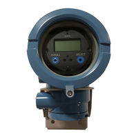
Emerson MICRO MOTION 2700 Configuration And Use Manual (374 pages)
Transmitters with Analog Outputs
Brand:
Emerson
| Category:
Transmitter
| Size: 5.35 MB
Table of Contents
Table of Contents
3
Part I Getting Started
9
Chapter 1 Before You Begin
11
About this Manual
11
Transmitter Model Code
11
Communications Tools and Protocols
11
Additional Documentation and Resources
12
Chapter 2 Quick Start
15
Power up the Transmitter
15
Check Flowmeter Status
15
Make a Startup Connection to the Transmitter
17
Characterize the Flowmeter (if Required)
18
Sources and Formats for Characterization Parameters
18
Verify Mass Flow Measurement
21
Verify the Zero
22
Verify the Zero Using Prolink II
22
Verify the Zero Using Prolink III
23
Terminology Used with Zero Verification and Zero Calibration
24
Part II Configuration and Commissioning
25
Chapter 3 Introduction to Configuration and Commissioning
27
Configuration Flowchart
27
Default Values and Ranges
29
Enable Access to the Off-Line Menu of the Display
29
Disable Write-Protection on the Transmitter Configuration
29
Restore the Factory Configuration
30
Chapter 4 Configure Process Measurement
31
Configure Mass Flow Measurement
31
Configure Mass Flow Measurement Unit
31
Configure Flow Damping
34
Configure Mass Flow Cutoff
35
Configure Volume Flow Measurement for Liquid Applications
37
Configure Volume Flow Type for Liquid Applications
37
Configure Volume Flow Measurement Unit for Liquid Applications
38
Configure Volume Flow Cutoff
41
Configure Gas Standard Volume (GSV) Flow Measurement
42
Configure Volume Flow Type for Gas Applications
43
Configure Standard Gas Density
43
Configure Gas Standard Volume Flow Measurement Unit
44
Configure Gas Standard Volume Flow Cutoff
47
Configure Flow Direction
48
Options for Flow Direction
49
Configure Density Measurement
53
Configure Density Measurement Unit
54
Configure Slug Flow Parameters
55
Configure Density Damping
56
Configure Density Cutoff
58
Configure Temperature Measurement
58
Configure Temperature Measurement Unit
59
Configure Temperature Damping
59
Configure the Petroleum Measurement Application
61
Configure Petroleum Measurement Using Prolink II
61
Configure Petroleum Measurement Using Prolink III
62
Configure Petroleum Measurement Using the Field Communicator
64
API Reference Tables
65
Configure the Concentration Measurement Application
66
Configure Concentration Measurement Using Prolink II
66
Configure Concentration Measurement Using Prolink III
69
Configure Concentration Measurement Using the Field Communicator
72
Standard Matrices for the Concentration Measurement Application
74
Derived Variables and Calculated Process Variables
75
Configure Pressure Compensation
77
Configure Pressure Compensation Using Prolink II
77
Configure Pressure Compensation Using Prolink III
79
Configure Pressure Compensation Using the Field Communicator
81
Options for Pressure Measurement Unit
82
Chapter 5 Configure Device Options and Preferences
85
Configure the Transmitter Display
85
Configure the Language Used for the Display
85
Configure the Process Variables Shown on the Display
86
Configure the Precision of Variables Shown on the Display
87
Configure the Refresh Rate of Data Shown on the Display
88
Enable or Disable Automatic Scrolling through the Display Variables
89
Enable or Disable the Display Backlight
89
Enable or Disable Status LED Blinking
90
Enable or Disable Operator Actions from the Display
90
Enable or Disable Totalizer Start/Stop from the Display
91
Enable or Disable Totalizer Reset from the Display
91
Enable or Disable the Acknowledge All Alarms Display Command
92
Configure Security for the Display Menus
93
Configure Response Time Parameters
94
Configure Update Rate
95
Configure Calculation Speed (Response Time)
97
Configure Alarm Handling
97
Configure Fault Timeout
98
Configure Status Alarm Severity
98
Configure Informational Parameters
102
Configure Descriptor
103
Configure Message
103
Configure Date
104
Configure Sensor Serial Number
104
Configure Sensor Material
105
Configure Sensor Liner Material
105
Configure Sensor Flange Type
106
Chapter 6 Integrate the Meter with the Control System
107
Configure the Transmitter Channels
107
Configure the Ma Output
108
Configure Ma Output Process Variable
108
Configure Lower Range Value (LRV) and Upper Range Value (URV)
110
Configure AO Cutoff
112
Configure Added Damping
113
Configure Ma Output Fault Action and Ma Output Fault Level
115
Configure the Frequency Output
116
Configure Frequency Output Process Variable
116
Configure Frequency Output Polarity
118
Configure Frequency Output Scaling Method
119
Configure Frequency Output Maximum Pulse Width
120
Configure Frequency Output Fault Action and Frequency Output Fault Level
121
Configure the Discrete Output
122
Configure Discrete Output Source
123
Configure Discrete Output Polarity
126
Configure Discrete Output Fault Action
127
Configure Events
128
Configure a Basic Event
129
Configure an Enhanced Event
129
Configure Digital Communications
132
Configure Hart/Bell 202 Communications
132
Configure HART/RS-485 Communications
137
Configure Modbus/Rs-485 Communications
138
Configure Digital Communications Fault Action
139
Chapter 7 Completing the Configuration
143
Test or Tune the System Using Sensor Simulation
143
Sensor Simulation
144
Back up Transmitter Configuration
145
Enable Write-Protection on the Transmitter Configuration
146
Chapter 8 Set up the Weights & Measures Application
147
Weights & Measures Application
147
Set up the Weights & Measures Application Using Prolink II
148
Set up the Weights & Measures Application Using Prolink III
151
Part III Operations, Maintenance, and Troubleshooting
155
Chapter 9 Transmitter Operation
157
Record the Process Variables
157
View Process Variables
158
View Process Variables Using the Display
158
View Process Variables Using Prolink III
159
View Transmitter Status Using the Status LED
160
View and Acknowledge Status Alarms
160
View and Acknowledge Alarms Using the Display
160
View and Acknowledge Alarms Using Prolink II
163
View and Acknowledge Alerts Using Prolink III
164
View Alarms Using the Field Communicator
164
Alarm Data in Transmitter Memory
165
Read Totalizer and Inventory Values
165
Start and Stop Totalizers and Inventories
166
Start and Stop Totalizers and Inventories Using the Display
166
Reset Totalizers
168
Reset Totalizers Using the Display
168
Reset Inventories
169
Advertisement
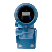
Emerson MICRO MOTION 2700 Configuration And Use Manual (338 pages)
with FOUNDATION Fieldbus
Brand:
Emerson
| Category:
Transmitter
| Size: 5.79 MB
Table of Contents
Table of Contents
3
Getting Started
9
Chapter 1 Before You Begin
11
About this Manual
11
Communication Methods
11
Additional Documentation and Resources
12
Chapter 2 Quick Start
13
Power up the Transmitter
13
Check Meter Status
13
Transmitter Status Reported by LED
14
Determine the FOUNDATION Fieldbus Unique Device ID
15
Make a Startup Connection to the Transmitter
15
Verify Mass Flow Measurement
15
Part II Configuration and Commissioning
17
Chapter 3 Introduction to Configuration and Commissioning
19
Configuration Flowchart
19
Default Values and Ranges
21
Enable Access to the Off-Line Menu of the Display
21
Disable Write-Protection on the Transmitter Configuration
21
Place Function, Transducer, and Resource Blocks in OOS Mode
22
Lockout FOUNDATION Fieldbus Hosts
22
Restore the Factory Configuration
23
Enable or Disable Fieldbus Write Lock
23
Chapter 4 Configure Process Measurement
25
Configure Mass Flow Measurement
25
Configure Mass Flow Measurement Unit
25
Configure Flow Damping
28
Configure Mass Flow Cutoff
29
Configure Volume Flow Measurement for Liquid Applications
30
Configure Volume Flow Type for Liquid Applications
30
Configure Volume Flow Measurement Unit for Liquid Applications
30
Configure Volume Flow Cutoff
33
Configure GSV Flow Measurement
34
Configure Volume Flow Type for Gas Applications
34
Configure Standard Density of Gas
35
Configure Gas Standard Volume Flow Unit
35
Configure Gas Standard Volume Flow Cutoff
38
Configure Flow Direction
39
Options for Flow Direction
39
Configure Density Measurement
41
Configure Density Measurement Unit
41
Configure Two-Phase Flow Parameters
42
Configure Density Damping
43
Configure Density Cutoff
44
Configure Temperature Measurement
45
Configure Temperature Measurement Unit
45
Configure Temperature Damping
46
Effect of Temperature Damping on Process Measurement
47
Configure the Petroleum Measurement Application
47
Configure Petroleum Measurement Using Prolink III
47
Configure Petroleum Measurement Using the Field Communicator
49
API Tables Supported by the Petroleum Measurement Application
49
Set up Concentration Measurement
51
Configure Concentration Measurement Using Prolink III
51
Configure Concentration Measurement Using the Field Communicator
52
Standard Matrices for the Concentration Measurement Application
54
Derived Variables and Calculated Process Variables
55
Set up Concentration Measurement Using a Basic FF Host
56
Set Reference Temperature Values for Specific Gravity Using a Basic FF Host
57
Modify Matrix Names and Labels Using a Basic FF Host
57
Modify Extrapolation Alerts for Concentration Measurement Using a Basic FF Host
58
Select the Active Concentration Matrix Using a Basic FF Host
59
Configure Pressure Compensation
59
Configure Pressure Compensation Using Prolink III
60
Configure Pressure Compensation Using the Field Communicator
60
Options for Pressure Measurement Unit
61
Chapter 5 Configure Device Options and Preferences
63
Configure the Transmitter Display
63
Configure the Language Used for the Display
63
Configure the Process Variables and Diagnostic Variables Shown on the Display
64
Configure the Number of Decimal Places (Precision) Shown on the Display
65
Configure the Refresh Rate of Data Shown on the Display
66
Enable or Disable Automatic Scrolling through the Display Variables
66
Enable or Disable the Display Backlight
67
Enable or Disable Status LED Blinking
67
Enable or Disable Operator Actions from the Display
68
Enable or Disable Totalizer Start/Stop from the Display
68
Enable or Disable Totalizer Reset from the Display
69
Enable or Disable the Acknowledge All Alerts Display Command
69
Configure Security for the Display Menus
70
Configure Response Time Parameters
72
Configure Alert Handling
72
Configure Fault Timeout
72
Configure Status Alert Severity
73
Configure Informational Parameters
75
Configure Sensor Serial Number
76
Configure Sensor Material
76
Configure Sensor Liner Material
77
Configure Sensor Flange Type
77
Configure Descriptor
78
Chapter 6 Complete the Configuration
79
Back up Transmitter Configuration
79
Return Function Blocks to in Service (Auto) Mode
80
Part III Operations, Maintenance, and Troubleshooting
81
Chapter 7 Transmitter Operation
83
Record the Process Variables
83
View Process Variables
84
View Process Variables Using the Display
84
View Process Variables and Other Data Using Prolink III
85
View Process Variables Using the Field Communicator
85
View Transmitter Status Using the Status LED
86
View and Acknowledge Status Alerts
87
View and Acknowledge Alerts Using the Display
87
View and Acknowledge Alerts Using Prolink III
89
View Alerts Using the Field Communicator
90
View Alerts Using a Fieldbus Host
90
Alert Data in Transmitter Memory
91
Read Totalizer and Inventory Values
91
Start and Stop Totalizers and Inventories
92
Start and Stop Totalizers and Inventories Using the Display
92
Reset Totalizers
93
Reset Totalizers Using the Display
94
Reset Inventories
95
Chapter 8 Measurement Support
97
Options for Measurement Support
97
Use Smart Meter Verification (SMV)
97
SMV Requirements
98
SMV Test Preparation
98
Run SMV
99
View Test Data
102
Schedule Automatic Execution of the SMV Test
105
Zero the Meter
108
Validate the Meter
109
Alternate Method for Calculating the Meter Factor for Volume Flow
111
Perform a (Standard) D1 and D2 Density Calibration
111
Perform a D1 and D2 Density Calibration Using Prolink III
112
Perform a D1 and D2 Density Calibration Using an Enhanced FF Host
113
Perform Temperature Calibration
114
Perform Temperature Calibration Using a Fieldbus Host
115
Chapter 9 Troubleshooting
117
Status Alerts, Causes, and Recommendations
117
Flow Measurement Problems
124
Density Measurement Problems
126
Temperature Measurement Problems
127
Check Power Supply Wiring
128
Check Grounding
129
Check for Radio Frequency Interference (RFI)
129
Check for Two-Phase Flow (Slug Flow)
129
Check the Drive Gain
130
Collect Drive Gain Data
131
Check the Pickoff Voltage
131
Collect Pickoff Voltage Data
132
Check for Internal Electrical Problems
132
Check the Sensor Coils
132
Appendix A Transducer Blocks and Views
135
Descriptions of Transducer Block Table Entries
136
Measurement Transducer Blocks
137
View List for the Measurement Transducer Block
137
Emerson MICRO MOTION 2700 Configuration And Use Manual (282 pages)
Brand:
Emerson
| Category:
Transmitter
| Size: 8.46 MB
Table of Contents
Table of Contents
3
Chapter 1 Before You Begin
11
Overview
11
Safety
11
Determining Your Transmitter Type and Version
11
Transmitter Type, Installation Type, and Outputs Option Board
12
Version
13
Flowmeter Documentation
13
Using this Manual
13
Component Versions
14
Terminology
14
Communication Tools
15
Planning the Configuration
15
Pre-Configuration Worksheet
16
Micro Motion Customer Service
17
Chapter 2 Using the Transmitter Display
19
Overview
19
Components
19
Using the Optical Switches
20
Using the Display
20
Display Language
20
Viewing Process Variables
20
Display Menus
21
Display Password
21
Entering Floating-Point Values with the Display
22
Chapter 3 Connecting with Prolink II or Pocket Prolink Software
25
Overview
25
Requirements
25
Prolink II Configuration Upload/Download
26
Connecting from a PC to a Model 1700 or Model 2700 Transmitter
26
Connecting to the Service Port
27
Connecting to the RS-485 Terminals or an RS-485 Network
28
Connecting to the Primary Ma Output Terminals or to a HART Multidrop Network
30
Connecting from a PC to a Model 1500 or Model 2500 Transmitter
33
Connecting to the RS-485 Terminals or an RS-485 Network
33
Hart/Bell 202 Connections
36
Prolink II Language
37
Chapter 4 Connecting with the 275 HART Communicator or
39
Field Communicator
39
Overview
39
Communicator Models
39
Viewing the Device Descriptions
40
Using the 275 HART Communicator with the Model 2500
40
Connecting to a Transmitter
41
Connecting to Communication Terminals
41
Connecting to a Multidrop Network
43
Conventions Used in this Manual
43
HART Communicator Safety Messages and Notes
43
Chapter 5 Flowmeter Startup
45
Flowmeter Startup
45
Overview
45
Applying Power
46
Communication Methods after Power-Up
46
Performing a Loop Test
47
Trimming the Milliamp Outputs
48
Zeroing the Flowmeter
49
Preparing for Zero
49
Zero Procedure
50
Chapter 6 Required Transmitter Configuration
53
Overview
53
Characterizing the Flowmeter
54
When to Characterize
54
Characterization Parameters
54
How to Characterize
57
Configuring the Channels
57
Configuring the Measurement Units
57
Mass Flow Units
58
Volume Flow Units
59
Density Units
61
Temperature Units
61
Pressure Units
62
Configuring the Ma Output(S)
62
Configuring the Frequency Output(S)
62
Configuring the Discrete Output(S)
62
Configuring the Discrete Input
63
Establishing a Meter Verification Baseline
63
Chapter 7 Using the Transmitter
65
Overview
65
Special Applications
65
Recording Process Variables
66
Viewing Process Variables
66
With the Display
66
With Prolink II
66
With a Communicator
67
Viewing Transmitter Status and Alarms
67
Using the Status LED
67
Using the Display
67
Using Prolink II
69
Using the Communicator
69
Acknowledging Alarms
69
Using the Totalizers and Inventories
70
Viewing the Totalizers and Inventories
70
Controlling Totalizers and Inventories
71
Chapter 8 Optional Configuration
75
Overview
75
Configuration Map
75
How to Access a Parameter for Configuration
75
Configuring Standard Volume Flow Measurement for Gas
77
Using the Gas Wizard
77
Creating Special Measurement Units
78
About Special Measurement Units
78
Special Measurement Unit Procedure
79
Configuring the Petroleum Measurement Application (API Feature)
80
About the Petroleum Measurement Application
80
Configuring Cutoffs
82
Cutoffs and Volume Flow
83
Interaction with the AO Cutoffs
83
Configuring the Damping Values
83
Damping and Volume Measurement
84
Interaction with the Added Damping Parameter
84
Interaction with the Update Rate
84
Configuring the Update Rate
84
Effects of Special Mode
85
Configuring the Flow Direction Parameter
86
Configuring Events
89
Changing Event Setpoints from the Display
89
Configuring Slug Flow Limits and Duration
90
Configuring Fault Handling
91
Status Alarm Severity
91
Fault Timeout
95
Configuring the Display
95
Update Period
95
Language
95
Enabling and Disabling Display Functions
95
Changing the Scroll Rate
96
Changing the Display Password
96
Changing the Display Variables and Display Precision
96
Fixing Display Variable 1 to the Primary Ma Output
96
Configuring Digital Communications
97
Configuring Device Settings
97
Configuring Sensor Parameters
97
Configuring Write-Protect Mode
98
Chapter 9 Pressure Compensation, Temperature Compensation, and Polling
99
Overview
99
Pressure Compensation
99
Options
99
Pressure Correction Factors
100
Configuration
100
External Temperature Compensation
101
Configuring Polling
103
Advertisement
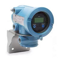
Emerson MICRO MOTION 2700 Configuration And Use Manual (268 pages)
Transmitters with Intrinsically Safe Outputs
Brand:
Emerson
| Category:
Transmitter
| Size: 6.05 MB
Table of Contents
Table of Contents
3
Part I Getting Started
9
Chapter 1 Before You Begin
11
About this Manual
11
Transmitter Model Code
11
Communications Tools and Protocols
12
Additional Documentation and Resources
12
Chapter 2 Quick Start
13
Power up the Transmitter
13
Check Meter Status
13
Transmitter Status Reported by LED
14
Make a Startup Connection to the Transmitter
15
Verify Mass Flow Measurement
15
Verify the Zero
15
Terminology Used with Zero Verification and Zero Calibration
16
Part II Configuration and Commissioning
19
Chapter 3 Introduction to Configuration and Commissioning
21
Configuration Flowchart
21
Default Values and Ranges
23
Enable Access to the Off-Line Menu of the Display
23
Disable Write-Protection on the Transmitter Configuration
23
Set the HART Lock
24
Restore the Factory Configuration
24
Chapter 4 Configure Process Measurement
27
Configure Mass Flow Measurement
27
Configure Mass Flow Measurement Unit
27
Configure Flow Damping
30
Configure Mass Flow Cutoff
31
Configure Volume Flow Measurement for Liquid Applications
32
Configure Volume Flow Type for Liquid Applications
33
Configure Volume Flow Measurement Unit for Liquid Applications
33
Configure Volume Flow Cutoff
36
Configure GSV Flow Measurement
38
Configure Volume Flow Type for Gas Applications
38
Configure Standard Density of Gas
38
Configure Gas Standard Volume Flow Unit
40
Configure Gas Standard Volume Flow Cutoff
43
Configure Flow Direction
44
Options for Flow Direction
45
Configure Density Measurement
50
Configure Density Measurement Unit
50
Configure Two-Phase Flow Parameters
51
Configure Density Damping
53
Configure Density Cutoff
54
Configure Temperature Measurement
55
Configure Temperature Measurement Unit
55
Configure Temperature Damping
56
Effect of Temperature Damping on Process Measurement
56
Configure Temperature Input
57
Configure the Petroleum Measurement Application
57
Configure Petroleum Measurement Using Prolink III
57
Set up Temperature Data for Petroleum Measurement Using Prolink III
59
Configure Petroleum Measurement Using the Field Communicator
60
API Tables Supported by the Petroleum Measurement Application
62
Set up Concentration Measurement
63
Configure Concentration Measurement Using Prolink III
63
Configure Concentration Measurement Using the Field Communicator
65
Standard Matrices for the Concentration Measurement Application
67
Derived Variables and Calculated Process Variables
68
Configure Pressure Compensation
70
Configure Pressure Compensation Using Prolink III
70
Configure Pressure Compensation Using the Field Communicator
72
Options for Pressure Measurement Unit
73
Chapter 5 Configure Device Options and Preferences
75
Configure the Transmitter Display
75
Configure the Language Used for the Display
75
Configure the Process Variables and Diagnostic Variables Shown on the Display
75
Configure the Number of Decimal Places (Precision) Shown on the Display
77
Configure the Refresh Rate of Data Shown on the Display
78
Enable or Disable Automatic Scrolling through the Display Variables
78
Enable or Disable the Display Backlight
79
Enable or Disable Status LED Blinking
79
Enable or Disable Operator Actions from the Display
80
Enable or Disable Totalizer Start/Stop from the Display
80
Enable or Disable Totalizer Reset from the Display
81
Enable or Disable the Acknowledge All Alerts Display Command
81
Configure Security for the Display Menus
82
Configure Response Time Parameters
83
Configure Update Rate
84
Configure Response Time
86
Configure Alert Handling
86
Configure Fault Timeout
87
Configure Status Alert Severity
87
Configure Informational Parameters
91
Configure Sensor Serial Number
91
Configure Sensor Material
92
Configure Sensor Liner Material
92
Configure Sensor Flange Type
92
Configure Descriptor
93
Configure Message
93
Configure Date
94
Chapter 6 Integrate the Meter with the Control System
95
Configure the Transmitter Channels
95
Configure the Ma Output
96
Configure Ma Output Process Variable
96
Configure Lower Range Value (LRV) and Upper Range Value (URV)
99
Configure AO Cutoff
101
Configure Added Damping
102
Configure Ma Output Fault Action and Ma Output Fault Level
104
Configure the Frequency Output
105
Configure Frequency Output Process Variable
105
Configure Frequency Output Polarity
107
Configure Frequency Output Scaling Method
108
Configure Frequency Output Fault Action and Frequency Output Fault Level
109
Configure the Discrete Output
110
Configure Discrete Output Source
111
Configure Discrete Output Polarity
113
Configure Discrete Output Fault Action
113
Configure Events
114
Configure a Basic Event
115
Configure an Enhanced Event
115
Configure Digital Communications
117
Configure Hart/Bell 202 Communications
118
Configure Digital Communications Fault Action
124
Chapter 7 Complete the Configuration
127
Test or Tune the System Using Sensor Simulation
127
Sensor Simulation
128
Back up Transmitter Configuration
129
Enable Write-Protection on the Transmitter Configuration
129
Part III Operations, Maintenance, and Troubleshooting
131
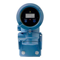
Emerson MICRO MOTION 2700 Configuration And Use Manual (204 pages)
with PROFIBUS-PA
Brand:
Emerson
| Category:
Transmitter
| Size: 4.92 MB
Table of Contents
Table of Contents
3
Chapter 1 Before You Begin
9
Overview
9
Safety
9
Determining Transmitter Information
9
PROFIBUS-PA Functionality
10
Determining Version Information
10
Communication Tools
11
Planning the Configuration
12
Pre-Configuration Worksheet
13
Flowmeter Documentation
14
Micro Motion Customer Service
14
Chapter 2 Startup
15
Overview
15
Applying Power
15
Setting the Node Address
16
Configuring the Analog Input Function Block Channels
16
Setting the I/O Mode
18
Overriding the Status Byte Format
19
Configuring the Totalizer Block Mode
19
Configuring Pressure Compensation
21
Pressure Compensation Values
21
Enabling Pressure Compensation
22
Configuring a Pressure Source
23
Configuring Temperature Compensation
24
Enabling External Temperature Compensation
24
Configuring a Temperature Source
25
Chapter 3 Calibration
27
Overview
27
Characterization, Smart Meter Verification, Meter Validation, and Calibration
27
Characterization
28
Smart Meter Verification
28
Meter Validation and Meter Factors
28
Calibration
28
Comparison and Recommendations
29
Performing a Characterization
30
Characterization Parameters
30
How to Characterize
32
Performing Smart Meter Verification
34
Preparing for the Smart Meter Verification Test
34
Running the Smart Meter Verification Test
34
Reading and Interpreting Smart Meter Verification Test Results
39
Setting up Automatic or Remote Execution of the Smart Meter Verification Test
42
Performing Meter Validation
43
Performing Zero Calibration
45
Preparing for the Zeroing Procedure
45
Zeroing Procedure
45
Performing Density Calibration
47
Preparing for Density Calibration
48
Density Calibration Procedure
48
Performing Temperature Calibration
52
Configuration
55
Overview
55
Default Target Mode
55
Configuration Map
55
Chapter 4 Configuration
55
Configuring Standard Volume Flow Measurement for Gas
56
Changing the Measurement Units
59
Configuring the Petroleum Measurement Application
63
About the Petroleum Measurement Application
63
Configuration Procedure
65
Configuring the Concentration Measurement Application
67
About the Concentration Measurement Application
67
Configuration Procedure
69
Changing the Output Scale
70
Changing Process Alarms
71
Alarm Values
71
Alarm Hysteresis
73
Configuring Status Alarm Severity
74
Changing the Damping Values
76
Damping and Volume Measurement
78
Changing Slug Flow Limits and Duration
78
Configuring Cutoffs
79
Changing the Measurement Mode Parameter
81
Configuring Sensor Parameters
82
Configuring the Display
83
Enabling and Disabling Display Functions
83
Changing the Scroll Rate
85
Changing the Update Period
85
Changing the Off-Line Password
85
Changing the Display Language
85
Changing the Display Variables and Precision
86
Enabling LD Optimization
88
Chapter 5 Operation
91
Overview
91
Using the I&M Functions
91
Recording Process Variables
91
Viewing Process Variables
92
With the Display
92
With Prolink II
93
With PROFIBUS EDD
93
With Bus Parameters
93
Using Sensor Simulation Mode
93
Accessing Diagnostic Information with a PROFIBUS Host
94
Viewing Transmitter Status and Alarms
94
With the Display
94
With Prolink II
95
With EDD
96
With Bus Parameters
96
Using the Totalizers and Inventories
96
Viewing Current Values for Totalizers and Inventories
96
Controlling the Totalizers and Inventories
98
Troubleshooting
101
Overview
101
Guide to Troubleshooting Topics
101
Transmitter Does Not Operate
101
Emerson MICRO MOTION 2700 Installation Manual (122 pages)
Brand:
Emerson
| Category:
Transmitter
| Size: 12.81 MB
Table of Contents
Table of Contents
3
Chapter 1 Planning
5
Meter Components
5
Installation Types
5
Maximum Cable Lengths between Sensor and Transmitter
10
Output Options
11
Environmental Limits
12
Hazardous Area Classifications
12
Power Requirements
12
Orientation
13
Accessibility for Maintenance
14
Chapter 2 Mounting and Sensor Wiring for Integral Installations
15
Mounting and Sensor Wiring
15
Rotate the Transmitter on the Sensor (Optional)
15
Rotate the User Interface on the Transmitter (Optional)
17
Ground the Meter Components
18
Chapter 3 Mounting and Sensor Wiring for 4-Wire Remote Installations
20
Mounting Options
20
Prepare the 4-Wire Cable
24
Wire the Transmitter to the Sensor
27
Rotate the User Interface on the Transmitter (Optional)
29
Ground the Meter Components
30
Chapter 4 Mounting and Sensor Wiring for 9-Wire Remote Installations
32
Mounting Options
32
Prepare the 9-Wire Cable
34
Wire the Transmitter to the Sensor Using Jacketed Cable
40
Wire the Transmitter to the Sensor Using Shielded or Armored Cable
43
Rotate the User Interface on the Transmitter (Optional)
48
Ground the Meter Components
50
Chapter 5 Mounting and Sensor Wiring for Remote Core Processor with Remote Sensor Installations
52
Mounting Options
52
Mount the Remote Core Processor
56
Prepare the 4-Wire Cable
57
Micro Motion
58
Wire the Transmitter to the Remote Core Processor
60
Prepare the 9-Wire Cable
62
Wire the Remote Core Processor to the Sensor Using Jacketed Cable
68
Wire the Remote Core Processor to the Sensor Using Shielded or Armored Cable
71
Rotate the User Interface on the Transmitter (Optional)
75
Ground the Meter Components
77
Chapter 6 Wiring the Power Supply
80
Wire the Power Supply
80
Chapter 7 I/O Wiring for Model 1700 and Model 2700 Transmitters with Analog Outputs
81
Basic Analog Wiring
81
Hart/Analog Single Loop Wiring
82
RS-485 Point-To-Point Wiring
83
HART Multidrop Wiring
83
Chapter 8 I/O Wiring for Model 1700 and Model 2700 Transmitters with Intrinsically Safe Outputs
85
Safe Area Ma Output Wiring
85
Safe Area Hart/Analog Single-Loop Wiring
86
Safe Area HART Multidrop Wiring
87
Safe Area Frequency Output/Discrete Output Wiring
88
Hazardous Area Wiring
88
Galvanic Isolator
91
Emerson MICRO MOTION 2700 Installation Manual (80 pages)
Emerson Satellite Radio User Manual
Brand:
Emerson
| Category:
Transmitter
| Size: 6.88 MB
Table of Contents
Table of Contents
3
Chapter 1 Before You Begin
5
Overview
5
Safety
5
Flowmeter Components
6
Transmitter Type, Installation Type, and Outputs Option Board
6
Transmitter Installation Procedures
7
Flowmeter Documentation
7
Micro Motion Customer Service
8
Chapter 2 Installing the Transmitter
9
Overview
9
Installation Architecture
9
Installation Types
10
Determining an Appropriate Location
11
Environmental Requirements
11
Hazardous Area Classifications
11
Power Source
11
Maximum Cable Lengths
13
Accessibility for Maintenance
13
Mounting the Transmitter
13
Integral Installations
14
4-Wire Remote or Remote Core Processor with Remote Transmitter Installations
15
9-Wire Remote Installations
16
Mounting the Remote Core Processor
17
Grounding the Flowmeter Components
19
Supplying Power
20
Rotating the Display
20
Chapter 3 Wiring the Transmitter to the Sensor
23
Overview
23
Cable Types
23
4-Wire Cable
24
Wiring for 4-Wire Remote Installations
24
Wiring for 9-Wire Remote Installations
26
Wiring for Remote Core Processor with Remote Transmitter Installations
27
Chapter 4 Output Wiring - Model 1700/2700 Analog Transmitters
33
Overview
33
Output Terminals and Output Types
33
Output Wiring
33
Chapter 5 Output Wiring - Model 1700/2700 Intrinsically Safe Transmitters
37
Overview
37
Output Terminals and Output Types
37
Safe Area Output Wiring
38
Safe Area Ma Output Wiring
38
Safe Area Frequency/Discrete Output Wiring
40
Hazardous Area Output Wiring
41
Hazardous Area Safety Parameters
41
Hazardous Area Ma Output Wiring
43
Hazardous Area Frequency/Discrete Output Wiring
43
Chapter 6 Output Wiring - Model 2700 Configurable I/O Transmitters
45
Overview
45
Channel Configuration
45
Ma Output Wiring
46
Frequency Output Wiring
48
Discrete Output Wiring
51
Discrete Input Wiring
54
Emerson MICRO MOTION 2700 Installation Manual (92 pages)
MVD Transmitters
Brand:
Emerson
| Category:
Transmitter
| Size: 16.23 MB
Table of Contents
Table of Contents
3
October 2018 MMI
6
Chapter 1 Planning the Installation
7
About this Document
7
Installation Architecture
7
Hazardous Area Installations
8
Chapter 2 Transmitter Output Installation
9
Transmitter Output Installation: Analog Outputs for Model 1700/2700 Transmitters
10
Transmitter Output Installation Model 2750 Transmitter with Configurable Inputs and Outputs
11
Transmitter Output Installation: Model 2700 with Configurable Inputs and Outputs
12
Transmitter Output Installation: Profibus-PA Outputs for Model 1700/2700 Transmitters
13
Transmitter Output Installation Model 1700/2700 with Intrinsically Safe Installation
14
Transmitter Output Installation Model 1700/2700 with Fieldbus
15
Chapter 3 Model 1700/2700 4-Wire Installation
17
Model 1700/2700 4-Wire Installation: Remote Transmitter to Enhanced Core Processor Mounted on Sensor
18
Model 1700/2700 Transmitter 4-Wire Installation - Remote Transmitter to Core Processor Mounted on Sensor
19
Model 1700-2700 Transmitter 4-Wire Remote Transmitter Installation to Core Processor Mounted on CMF400 Sensor with Booster Amplifier
20
Model 1700/2700 Transmitter 4-Wire Remote Transmitter to Core Processor Mounted on D600 Sensor
21
Chapter 4 Direct Host 4-Wire Installation
23
Direct Host 4-Wire Installation - Core Processor to Direct Host through a Safety Barrier
24
Direct Host 4-Wire Installation of Enhanced Core Processor to a Direct Host through a Safety Barrier
25
Chapter 5 Model 800 Enhanced Core Processor
27
Chapter 6 Model 2750 4-Wire Installation
29
Chapter 7 Model 1500/2500 4-Wire Installation
31
Remote Transmitter to Enhanced Core Processor Mounted on Sensor
32
Remote Transmitter to Core Processor Mounted on CMF, F, H, R, CNG, and T Sensor
33
Remote Transmitter to Core Processor Mounted on CMF400 Sensor with Booster Amplifier
34
Remote Transmitter to Core Processor Mounted on D600 Sensor
35
Chapter 8 Model 3700 Transmitter 4-Wire Installation
37
Model 3700 Transmitter to Enhanced Core Processor Mouted on Sensor
38
Model 3700 Transmitter to Core Processor Mounted on CMF, F, H, R, CNF, and T Sensors
39
Remote Model 3700 Transmitter to Core Processor Mounted on CMF400 Sensor with Booster Amplifier
40
Model 3700 Remote Transmitter to Core Processor Mounted on D600 Sensor
41
Chapter 9 Model 3500 Transmitter 4-Wire Installation
43
Remote Model 3500 Transmitter to Enhanced Core Processor Mounted on Sensor
44
Remote Model 3500 Transmitter to Core Processor Mounted on CMF, F, H, R, CNG and T Sensors
45
Remote Model 3500 Transmitter to Core Processor Mounted on CMF400 Sensor with Booster Amplifier
46
Remote Model 3500 Transmitter to Core Processor Mounted on D600 Sensor
47
MMI-20001965 October
27
Chapter 10 Model LFT 4-Wire Installation to LF Sensor
49
Profibus-PA Transmitter Remotely Mounted to LF Sensor
50
Ma/Fo Transmitter Remotely Mounted to LF Sensor
51
FOUNDATION Fieldbus ™ Transmitter Remotely Mounted to LF Sensor
52
Config I/O Transmitter Remotely Mounted to LF Sensor
53
DIN Rail Transmitter Remotely Mounted to LF Sensor
54
Chapter 11 Model 1700/2700 Transmitter 9-Wire Integral Installations
55
Model 1700/2700 Transmitter with Integrally-Mounted Processor to Junction Box on CMF, F, H, T, D, and DL Sensors
56
Model 1700/2700 Transmitter with Integrally-Mounted Core Processor to 9-Wire Junction Box on CMF400 Sensor with Booster Amplifier
57
Model 1700/2700 Transmitter with Integrally-Mounted Core Processor to Junction Box on D600 Sensor
58
Model 1700/2700 Transmitter with Integrally-Mounted Core Processor to 9-Wire Junction Box on DT Sensor
59
Emerson MICRO MOTION 2700 Installation Manual (80 pages)
Brand:
Emerson
| Category:
Transmitter
| Size: 6.25 MB
Table of Contents
Table of Contents
5
Chapter 1 Before You Begin
7
Overview
7
Safety
7
Flowmeter Components
8
Transmitter Type, Installation Type, and Outputs Option Board
8
Abbreviations Used in this Manual
9
Transmitter Installation Procedures
9
Flowmeter Documentation
9
Chapter 2 Installing the Transmitter
11
Overview
11
Determining an Appropriate Location
11
Environmental Requirements
13
Hazardous Area Classifications
13
Power Source
13
Flowmeter Cable Lengths
15
Accessibility for Maintenance
15
Mounting the Transmitter
15
Integral Installations
16
4-Wire Remote or Remote Core Processor with Remote Transmitter Installations
17
9-Wire Remote Installations
18
Mounting the Remote Core Processor
19
Grounding the Flowmeter Components
21
Grounding for Integral Installations
21
Grounding for 4-Wire Remote Installations
21
Grounding for 9-Wire Remote Installations
22
Grounding for Remote Core Processor with Remote Transmitter Installations
22
Supplying Power
22
Rotating the Display
23
Chapter 3 Wiring the Transmitter to the Sensor
25
Overview
25
Cable Types
25
4-Wire Cable
25
Wiring for 4-Wire Remote Installations
26
Wiring for 9-Wire Remote Installations
27
Wiring for Remote Core Processor with Remote Transmitter Installations
28
Chapter 4 Output Wiring - Model 1700/2700 an Transmitters
35
Overview
35
Output Terminals and Output Types
35
Output Wiring
35
Chapter 5 Output Wiring - Model 1700/2700 IS Transmitters
39
Overview
39
Output Terminals and Output Types
39
Safe Area Output Wiring
40
Safe Area Ma Output Wiring
40
Safe Area Frequency/Discrete Output Wiring
42
Hazardous Area Output Wiring
43
Hazardous Area Safety Parameters
43
Hazardous Area Ma Output Wiring
45
Hazardous Area Frequency/Discrete Output Wiring
45
Emerson MICRO MOTION 2700 Configuration And Use Manual Supplement (44 pages)
with Intrinsically Safe Outputs
Brand:
Emerson
| Category:
Transmitter
| Size: 1.09 MB
Table of Contents
Table of Contents
3
Chapter 1 Configure Device Options and Preferences
7
Configure Display Variables and Display Precision
7
Chapter 2 Integrate the Meter with the Control System
9
Configure Channel B
9
Configure the Ma Outputs
10
Configure the Frequency Output
16
Configure the Discrete Output
22
Configure Digital Communications
26
Configure Events
31
Chapter 3 Set up the Weights & Measures Application
35
Locale-Specific Commissioning
35
Chapter 4 Operate the Transmitter
37
View Process Data
37
Appendix A Display Codes and Abbreviations
39
Display Codes for Process Variables
39
Codes and Abbreviations Used in Display Menus
40
Emerson MICRO MOTION 2700 Product Data Sheet (28 pages)
Micro Motion 3000 Series Transmitters and Discrete Controllers
Brand:
Emerson
| Category:
Transmitter
| Size: 0.91 MB
Table of Contents
Table of Contents
3
Housings
4
Applications
4
Interface/Display
5
Electrical Connections
5
Input Signals
6
Output Signals
6
Environmental Specifications
8
Power Supply
8
Hazardous Area Classifications
9
Model 3100 Accessory
10
Model 3500/3700 Liquid Flow Performance
10
Model 3500/3700 Density Performance (Liquid Only)
11
Model 3500/3700 Gas Flow Performance
11
Weight
11
Dimensions
12
Ordering Information
16
Advertisement
Related Products
Emerson Micro Motion 2750
Emerson Micro Motion 2400S
Emerson Rosemount 2051
Emerson Rosemount 2051CF series
Emerson Rosemount 2088
Emerson Rosemount 2090F
Emerson Rosemount 2090P
Emerson Rosemount 2240S
Emerson Rosemount 2051HT
Emerson Rosemount 2051T
Emerson Categories
Controller
Control Unit
Transmitter
Measuring Instruments
Fan
More Emerson Manuals
Login
Sign In
OR
Sign in with Facebook
Sign in with Google
Upload manual
Upload from disk
Upload from URL