Sign In
Upload
Manuals
Brands
ST Manuals
Microcontrollers
STM32 Nucleo
ST STM32 Nucleo Manuals
Manuals and User Guides for ST STM32 Nucleo. We have
25
ST STM32 Nucleo manuals available for free PDF download: Programming Manual, User Manual, Application Note, Quick Start Manual
ST STM32 Nucleo Programming Manual (262 pages)
Brand:
ST
| Category:
Computer Hardware
| Size: 2 MB
Table of Contents
Table 1. Applicable Products
1
Table of Contents
2
About this Document
12
Typographical Conventions
12
List of Abbreviations for Registers
12
About the STM32 Cortex-M4 Processor and Core Peripherals
13
Figure 1. STM32 Cortex-M4 Implementation
13
System Level Interface
14
Integrated Configurable Debug
14
Cortex-M4 Processor Features and Benefits Summary
15
Cortex-M4 Core Peripherals
16
The Cortex-M4 Processor
17
Programmers Model
17
Processor Mode and Privilege Levels for Software Execution
17
Stacks
17
Core Registers
18
Table 2. Summary of Processor Mode, Execution Privilege Level, and Stack Usage
18
Table 3. Core Register Set Summary
18
Figure 2. Processor Core Registers
18
Table 4. PSR Register Combinations
20
Figure 3. APSR, IPSR and EPSR Bit Assignment
20
Figure 4. PSR Bit Assignment
20
Table 5. APSR Bit Definitions
21
Table 6. IPSR Bit Definitions
22
Table 7. EPSR Bit Definitions
23
Table 8. PRIMASK Register Bit Definitions
24
Table 9. FAULTMASK Register Bit Definitions
24
Figure 5. PRIMASK Bit Assignment
24
Figure 6. FAULTMASK Bit Assignment
24
Table 10. BASEPRI Register Bit Assignment
25
Table 11. CONTROL Register Bit Definitions
25
Figure 7. BASEPRI Bit Assignment
25
Exceptions and Interrupts
26
Data Types
26
The Cortex Microcontroller Software Interface Standard (CMSIS)
26
Memory Model
28
Figure 8. Memory Map
28
Memory Regions, Types and Attributes
29
Memory System Ordering of Memory Accesses
29
Table 12. Ordering of Memory Accesses
29
Behavior of Memory Accesses
30
Table 13. Memory Access Behavior
30
Software Ordering of Memory Accesses
31
Bit-Banding
32
Table 14. SRAM Memory Bit-Banding Regions
32
Table 15. Peripheral Memory Bit-Banding Regions
32
Figure 9. Bit-Band Mapping
33
Memory Endianness
34
Synchronization Primitives
34
Figure 10. Little-Endian Example
34
Programming Hints for the Synchronization Primitives
36
Table 16. CMSIS Functions for Exclusive Access Instructions
36
Exception Model
37
Exception States
37
Exception Types
37
Table 17. Properties of the Different Exception Types
38
Exception Handlers
39
Vector Table
40
Figure 11. Vector Table
40
Exception Priorities
41
Interrupt Priority Grouping
41
Exception Entry and Return
42
Figure 12. Cortex-M4 Stack Frame Layout
43
Fault Handling
44
Table 18. Exception Return Behavior
44
Fault Types
45
Table 19. Faults
45
Fault Escalation and Hard Faults
46
Fault Status Registers and Fault Address Registers
47
Lockup
47
Power Management
47
Table 20. Fault Status and Fault Address Registers
47
Entering Sleep Mode
48
Wakeup from Sleep Mode
48
External Event Input / Extended Interrupt and Event Input
49
Power Management Programming Hints
49
The STM32 Cortex-M4 Instruction Set
50
Instruction Set Summary
50
Table 21. Cortex-M4 Instructions
50
CMSIS Intrinsic Functions
58
Table 22. CMSIS Intrinsic Functions to Generate some Cortex-M4 Instructions
59
Table 23. CMSIS Intrinsic Functions to Access the Special Registers
59
About the Instruction Descriptions
60
Operands
60
Restrictions When Using PC or SP
60
Flexible Second Operand
60
Shift Operations
62
Figure 13. ASR #3
62
Figure 14. LSR #3
63
Figure 15. LSL #3
63
Figure 16. ROR #3
64
Figure 17. RRX #3
64
Address Alignment
65
PC-Relative Expressions
65
Conditional Execution
65
Table 24. Condition Code Suffixes
67
Instruction Width Selection
68
Memory Access Instructions
69
Table 25. Memory Access Instructions
69
Adr
70
LDR and STR, Immediate Offset
71
Table 26. Immediate, Pre-Indexed and Post-Indexed Offset Ranges
72
LDR and STR, Register Offset
73
LDR and STR, Unprivileged
74
LDR, PC-Relative
75
Table 27. Label-PC Offset Ranges
75
LDM and STM
76
PUSH and POP
78
LDREX and STREX
79
Clrex
80
General Data Processing Instructions
81
Table 28. Data Processing Instructions
81
ADD, ADC, SUB, SBC, and RSB
83
AND, ORR, EOR, BIC, and ORN
85
ASR, LSL, LSR, ROR, and RRX
86
Clz
87
CMP and CMN
88
MOV and MVN
89
Movt
91
REV, REV16, REVSH, and RBIT
92
SADD16 and SADD8
93
SHADD16 and SHADD8
94
SHASX and SHSAX
95
SHSUB16 and SHSUB8
96
SSUB16 and SSUB8
97
SASX and SSAX
98
TST and TEQ
99
UADD16 and UADD8
100
UASX and USAX
101
UHADD16 and UHADD8
102
UHASX and UHSAX
103
UHSUB16 and UHSUB8
104
Sel
105
Usad8
106
Usada8
107
USUB16 and USUB8
108
Multiply and Divide Instructions
109
Table 29. Multiply and Divide Instructions
109
MUL, MLA, and MLS
110
UMULL, UMAAL and UMLAL
111
SMLA and SMLAW
112
Smlad
114
SMLAL and SMLALD
115
SMLSD and SMLSLD
117
SMMLA and SMMLS
119
Advertisement
ST STM32 Nucleo User Manual (85 pages)
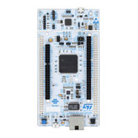
Nucleo-144 boards (MB1137)
Brand:
ST
| Category:
Computer Hardware
| Size: 2 MB
Table of Contents
Figure 1. Nucleo-144 Board (Top View)
1
Figure 2. Nucleo-144 Board (Bottom View)
1
Table of Contents
2
Features
6
Ordering Information
7
Table 1. Ordering Information
7
Codification
8
Table 2. Codification Explanation
8
Development Environment
9
System Requirements
9
Development Toolchains
9
Demonstration Software
9
Conventions
9
Table 3. ON/OFF Conventions
9
Quick Start
10
Getting Started
10
Hardware Layout and Configuration
11
Figure 3. Hardware Block Diagram
11
Figure 4. Top Layout
12
Figure 5. Bottom Layout
13
Mechanical Drawing
14
Figure 6. Nucleo-144 Board Mechanical Drawing in Millimeter
14
Cuttable PCB
15
Figure 7. Nucleo-144 Board Mechanical Drawing in Mil
15
Embedded ST-LINK/V2-1
16
Drivers
16
Table 4. CN4 States of the Jumpers
16
ST-LINK/V2-1 Firmware Upgrade
17
Figure 8. USB Composite Device
17
Using the ST-LINK/V2-1 to Program and Debug the On-Board STM32
18
Figure 9. Connecting the STM32 Nucleo-144 Board to Program the On-Board STM32
18
Using ST-LINK/V2-1 to Program and Debug an External STM32
19
Application
19
Table 5. Debug Connector CN6 (SWD)
19
Power Supply and Power Selection
20
Figure 10. Using ST-LINK/V2-1 to Program the STM32 on an External Application
20
Power Supply Input from ST-LINK/V2-1 USB Connector
21
External Power Supply Inputs
21
Table 6. JP1 Configuration Table
21
Table 7. External Power Sources
22
Table 8. Power Related Jumper
22
External Power Supply Output
23
Leds
24
Push-Buttons
24
Jp5 (IDD )
24
OSC Clock
25
OSC Clock Supply
25
OSC 32 Khz Clock Supply
26
USART Communication
26
Table 9. USART3 Pins
26
ST STM32 Nucleo User Manual (68 pages)
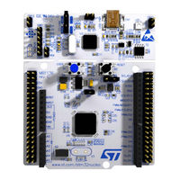
Nucleo-64 boards
Brand:
ST
| Category:
Motherboard
| Size: 3 MB
Table of Contents
Figure 1. STM32 Nucleo-64 Board
1
Table of Contents
2
Features
6
Ordering Information
7
Table 1. Ordering Information
7
Codification
8
Table 2. Codification Explanation
8
Development Environment
9
System Requirements
9
Development Toolchains
9
Demonstration Software
9
Conventions
9
Table 3. ON/OFF Conventions
9
Quick Start
10
Getting Started
10
NUCLEO-L476RG Bootloader Limitations
10
Hardware Configuration Variants
11
Hardware Layout and Configuration
12
Figure 2. Hardware Block Diagram
12
Figure 3. Top Layout
13
Figure 4. Bottom Layout
14
Figure 5. STM32 Nucleo Board Mechanical Dimensions
15
Pre-Cut PCB
16
Embedded ST-LINK/V2-1
16
Table 4. Jumper States
16
Driver
17
Figure 6. Typical Configuration
17
Figure 7. Updating the List of Drivers in Device Manager
17
ST-LINK/V2-1 Firmware Upgrade
17
Figure 8. Connecting the STM32 Nucleo Board to Program the On-Board STM32
18
STM32 Application
18
Using ST-LINK/V2-1 to Program and Debug an External
18
Using the ST-LINK/V2-1 to Program and Debug the STM32 on Board
18
Figure 9. Using ST-LINK/V2-1 to Program the STM32 on an External Application
19
Table 5. Debug Connector CN4 (SWD)
19
Power Supply and Power Selection
20
Power Supply Input from the USB Connector
20
Table 6. JP1 Configuration Table
20
External Power Supply Inputs: VIN and E5V
21
Table 7. External Power Sources
21
Table 8. Power-Related Jumper
21
External Power Supply Input: +3.3V
22
External Power Supply Output
22
Table 9. +3.3 V External Power Source
22
Leds
23
Push-Buttons
23
Jp6 (IDD)
23
OSC Clock
24
OSC Clock Supply
24
OSC 32 Khz Clock Supply
25
USART Communication
25
Solder Bridges
26
Table 10. Solder Bridges
26
Extension Connectors
27
Figure 10. NUCLEO-F030R8
28
Figure 11. NUCLEO-F070RB
28
Figure 12. NUCLEO-F072RB
29
Figure 13. NUCLEO-F091RC
29
Figure 14. NUCLEO-F103RB
30
Figure 15. NUCLEO-F302R8
30
Figure 16. NUCLEO-F303RE
31
Figure 17. NUCLEO-F334R8
31
Figure 18. NUCLEO-F401RE
32
Figure 19. NUCLEO-F411RE
32
Figure 20. NUCLEO-L053R8
33
Figure 21. NUCLEO-L073RZ and NUCLEO-L010RB
33
Figure 22. NUCLEO-L152RE
34
Figure 23. NUCLEO-L452RE
34
Figure 24. NUCLEO-L476RG
35
Figure 25. NUCLEO-F446RE
35
Figure 26. NUCLEO-F410RB
36
ARDUINO ® Connectors
37
Nucleo-F072Rb, Nucleo-F091Rc
37
Table 11. ARDUINO ® Connectors on NUCLEO-F030R8, NUCLEO-F070RB
38
Table 12. ARDUINO ® Connectors on NUCLEO-F103RB
39
Table 13. ARDUINO ® Connectors on NUCLEO-F302R8
40
Table 14. ARDUINO ® Connectors on NUCLEO-F303RE
41
Table 15. ARDUINO ® Connectors on NUCLEO-F334R8
43
Table 16. ARDUINO ® Connectors on NUCLEO-F401RE and NUCLEO-F411RE
43
Table 17. ARDUINO ® Connectors on NUCLEO-L053R8
45
Table 19. ARDUINO ® Connectors on NUCLEO-F446RE
48
Table 20. ARDUINO ® Connectors on NUCLEO-F410RB
49
Table 21. ARDUINO Connectors on NUCLEO-L152RE
50
Table 22. ARDUINO ® Connectors on NUCLEO-L452RE
52
ST Morpho Connector
53
Table 23. ARDUINO ® Connectors on NUCLEO-L476RG
53
Table 24. ST Morpho Connector on NUCLEO-F030R8
53
Table 25. ST Morpho Connector on NUCLEO-F070RB
54
Table 26. ST Morpho Connector on NUCLEO-F072RB, NUCLEO-F091RC, NUCLEO-F303RE, NUCLEO-F334R8
55
Table 27. ST Morpho Connector on NUCLEO-F103RB
55
Table 28. ST Morpho Connector on NUCLEO-F302R8
57
Table 29. ST Morpho Connector on NUCLEO-F401RE
58
Table 30. ST Morpho Connector on NUCLEO-L010RB
59
Nucleo-L053R8, Nucleo-L073Rz, Nucleo-L152Re
59
Table 31. ST Morpho Connector on NUCLEO-L452RE
60
Table 32. ST Morpho Connector on NUCLEO-L476RG
61
Table 33. ST Morpho Connector on NUCLEO-F410RB
62
Advertisement
ST STM32 Nucleo User Manual (46 pages)
USB demonstration kit
Brand:
ST
| Category:
Microcontrollers
| Size: 2 MB
Table of Contents
Figure 1. STM32F103 USB Demonstration Kit - Top View
1
Table of Contents
2
1 Introduction
6
2 Description
6
3 Boards Key Features
7
4 General System Description
8
Figure 2. STM32F103 USB Demonstration Kit - Block Diagram
8
5 Getting Started
9
System Requirements
9
Package Contents
9
Software Driver Installation
9
Figure 3. Device Manager Window - New USB Audio Device
10
6 Boards Layout
11
STM32 Controller Board Layout
11
TS4657 Audio Card Layout
11
Figure 4. STM32 Controller Board Layout
11
Figure 5. TS4657 Audio Card Board Layout
11
7 System Setup
12
Demonstration Kit Output Mode
12
Onboard Speaker Configuration
12
External Mono Speaker or Headphone Configuration
12
Figure 6. Onboard Speaker System Setup
12
External Amplified Stereo Output Configuration
13
Lineout Output Configuration
13
Microphone Record-Replay Mode
13
Figure 7. External Mono Speaker or Headphone System Setup
13
Figure 8. External Amplified Stereo Output System Setup
13
Figure 9. Lineout Output System Setup
13
Figure 10. Microphone Record-Replay Mode System Setup
14
8 Connectors of the STM32 Performance Line Controller Board
15
I 2 S Audio Connector P2
15
JTAG Connector CN1
15
Table 1. I 2 S Audio Connector Pins Description of the STM32 Controller Board
15
S Audio Connector of the STM32 Controller Board - Schematic
15
Table 2. JTAG Connector Pins Description
16
Figure 12. JTAG Connector
16
Figure 13. JTAG Connector CN1 - Schematic
16
9 Connectors and Functionality of the TS4657 Audio Card
17
I 2 S Audio Connector P1
17
Mono Jack Connector J4 and the Onboard Speaker U6
17
Table 3. I 2 S Audio Connector Pins Description of the TS4657 Audio Card
17
S Audio Connector of the TS4657 Audio Card - Schematic
17
TS2012 Stereo Output Terminal Connectors P2, P3
18
Table 4. Mono Jack Connector J4 Pins Description of the TS4657 Audio Card
18
Table 5. TS2012 Stereo Output Terminal Connectors P2, P3
18
Figure 15. Mono Jack Audio Connector J4 and the Onboard Speaker U6
18
TS4657 Stereo DAC Output Audio RCA Connectors J1, J3
19
Table 6. TS4657 Stereo DAC Output Audio RCA Connectors J1, J3
19
Figure 16. TS2012 Stereo Output Terminal Connectors P2, P3
19
Microphone Functionality
20
Figure 17. TS4657 Stereo DAC Output Audio RCA Connectors J1, J3
20
TS4657 Stereo Audio DAC Functionality
21
Figure 18. Microphone Functionality
21
TS4962 Mono Class-D Power Amplifier Functionality
22
Figure 19. TS4657 Stereo Audio DAC Functionality
22
TS2012 Stereo Class-D Power Amplifier Functionality
23
Figure 20. TS4962 Mono Class-D Amplifier Functionality
23
Figure 21. TS2012 Stereo Class-D Amplifier Functionality
24
ST STM32 Nucleo Application Note (49 pages)
How to get the best ADC accuracy in microcontrollers
Brand:
ST
| Category:
Microcontrollers
| Size: 1 MB
Table of Contents
Table of Contents
2
ADC Internal Principle
6
SAR ADC Internal Structure
6
Figure 1. Basic Schematic of SAR Switched-Capacitor ADC (Example of 10-Bit ADC)
6
Figure 2. Sample State
7
Figure 3. Hold State
7
Figure 4. Step 1: Compare with VREF/2
8
Figure 5. Step 2: if MSB = 0, then Compare with ¼VREF
8
Figure 6. Step 2: if MSB = 1, then Compare with ¾VREF
9
ADC Errors
10
Errors Due to the ADC Itself
10
Offset Error
10
Figure 7. Positive Offset Error Representation
11
Figure 8. Negative Offset Error Representation
11
Gain Error
12
Figure 9. Positive Gain Error Representation
12
Differential Linearity Error
13
Figure 10. Negative Gain Error Representation
13
Integral Linearity Error
14
Figure 11. Differential Linearity Error Representation
14
Figure 12. Integral Linearity Error Representation
15
Total Unadjusted Error
16
Figure 13. Total Unadjusted Error
16
Errors Due to the ADC Environment
17
Reference Voltage Noise
17
Reference Voltage / Power Supply Regulation
17
External Reference Voltage Parameters
18
Analog Input Signal Noise
18
ADC Dynamic Range Bad Match for Maximum Input Signal Amplitude
18
Effect of the Analog Signal Source Resistance
18
Figure 14. Input Signal Amplitude Vs. ADC Dynamic Range
18
Effect of Source Capacitance and Parasitic Capacitance of the PCB
19
Figure 15. Analog Signal Source Resistance Effect
19
Injection Current Effect
20
Temperature Influence
20
AIN , CAIN and C
20
I/O Pin Crosstalk
21
EMI-Induced Noise
21
Figure 18. Crosstalk between I/O Pins
21
Figure 19. EMI Sources
21
How to Get the Best ADC Accuracy
22
Reduce the Effects of ADC-Related ADC Errors
22
Minimize ADC Errors Related to External Environment of ADC
22
Reference Voltage / Power Supply Noise Minimization
22
Figure 20. Power Supply and Reference Decoupling for 100- and 144-Pin Packages
23
Figure 21. Power Supply Decoupling for 36-, 48- and 64-Pin Packages
23
Reference Voltage / Power-Supply Regulation
24
Analog-Input Signal Noise Elimination
24
Adding White Noise or Triangular Sweep to Improve Resolution
25
Figure 22. Simple Quasi-Triangular Source Using a Microcontroller Output
25
Matching the ADC Dynamic Range to the Maximum Signal Amplitude
26
Figure 23. Selecting the Reference Voltage
26
Figure 24. Preamplification
27
Analog Source Resistance Calculation
28
Figure 25. Worst Case Error: V
28
Ain Ref
28
Ain = Vref
28
Ain Ain Ain
28
Source Frequency Condition Vs. Source and Parasitic Capacitors
30
AIN and CAIN Vs. Source Frequency FAIN
30
Temperature-Effect Compensation
31
Minimizing Injection Current
31
Minimizing I/O Pin Crosstalk
31
EMI-Induced Noise Reduction
32
Figure 28. Shielding Technique
32
PCB Layout Recommendations
33
Figure 29. Separating the Analog and Digital Layouts
33
Figure 30. Separating the Analog and Digital Supplies
34
Component Placement and Routing
35
Software Methods to Improve Precision
35
Averaging Samples
35
Digital Signal Filtering
36
FFT for AC Measurement
37
ADC Calibration
38
Minimizing Internal CPU Noise
38
High Impedance Source Measurement
39
ADC Input Stage Problem
39
Figure 31. Typical Voltage Source Connection to ADC Input
39
Figure 32. Noise Observed on ADC Input Pin During ADC Conversions
39
Explanation of the Behavior
40
Figure 33. ADC Simplified Schematic of Input Stage - Sample and Hold Circuit
40
Figure 34. ADC Input Pin Noise Spikes from Internal Charge During Sampling Process
40
Minimizing Additional Errors
41
Figure 35. Effect of Sampling Time Extension
41
Figure 36. Charging the External Capacitor with too Short Time between Conversions
42
Source of Described Problem - ADC Design
45
Figure 37. Implementation of Sampling Switch
45
Figure 38. Parasitic Capacitances of Sampling Switch
46
Figure 39. Parasitic Current Example Inside ADC Structure
46
ST STM32 Nucleo User Manual (55 pages)
Brand:
ST
| Category:
Microcontrollers
| Size: 1 MB
Table of Contents
Figure 1. STM32 Nucleo Board (1)
1
Table of Contents
2
Ordering Information
6
Table 1. Ordering Information
6
Conventions
7
Table 2. ON/OFF Conventions
7
Quick Start
8
Getting Started
8
System Requirements
8
Features
9
Hardware Configuration Variants
9
Hardware Layout and Configuration
10
Figure 2. Hardware Block Diagram
10
Figure 3. Top Layout
11
Cutable PCB
12
Figure 4. Bottom Layout
12
Embedded ST-LINK/V2-1
13
Figure 5. Typical Configuration
13
Table 3. Jumper States
13
Drivers
14
Figure 6. Updating the List of Drivers in Device Manager
14
ST-LINK/V2-1 Firmware Upgrade
14
Using the ST-LINK/V2-1 to Program/Debug the STM32 on Board
14
Figure 7. Connecting the STM32 Nucleo Board to Program the On-Board STM32
15
Table 4. Debug Connector CN4 (SWD)
15
Using ST-LINK/V2-1 to Program/Debug an External STM32 Application
15
Power Supply and Power Selection
16
Power Supply Input from the USB Connector
16
Figure 8. Using ST-LINK/V2-1 to Program the STM32 on an External Application
16
External Power Supply Inputs: VIN and EV5
17
Table 5. JP1 Configuration Table
17
Table 6. External Power Sources
18
Table 7. Power-Related Jumper
18
External Power Supply Input: + 3V3
20
External Power Supply Output
20
Leds
20
Table 8. +3.3V Eternal Power Source
20
Push Buttons
21
Jp6 (IDD)
21
OSC Clock
22
OSC Clock Supply
22
OSC 32 Khz Clock Supply
23
USART Communication
23
Solder Bridges
25
Table 9. Solder Bridges
25
Extension Connectors
27
Figure 9. NUCLEO-F030R8
27
Figure 10. NUCLEO-F072RB
27
Figure 11. NUCLEO-F103RB
28
Figure 12. NUCLEO-F302R8
28
Figure 13. NUCLEO-F334R8
29
Figure 14. NUCLEO-F401RE
29
Figure 15. NUCLEO-F411RE
30
Figure 16. NUCLEO-L053R8
30
Figure 17. NUCLEO-L152RE
31
Arduino Connectors
32
Table 10. Arduino Connectors on NUCLEO-F030R8, NUCLEO-F072RB
32
Table 11. Arduino Connectors on NUCLEO-F103RB
34
Table 12. Arduino Connectors on NUCLEO-F302R8
36
Table 13. Arduino Connectors on NUCLEO-F334R8
37
Table 14. Arduino Connectors on NUCLEO-F401RE, NUCLEO-F411RE
39
Table 15. Arduino Connectors on NUCLEO-L053R8
40
Table 16. Arduino Connectors on NUCLEO-L152RE
41
Stmicroelectronics Morpho Connector
43
Table 17. Stmicroelectronics Morpho Connector on NUCLEO-F030R8
43
Nucleo-F334R8
44
Table 18. Stmicroelectronics Morpho Connector on NUCLEO-F072RB
44
Table 19. Stmicroelectronics Morpho Connector on NUCLEO-F103RB
45
Nucleo-F411Re
46
Table 20. Stmicroelectronics Morpho Connector on NUCLEO-F302R8
46
Table 21. Stmicroelectronics Morpho Connector on NUCLEO-F401RE
46
Nucleo-L053R8
48
Table 22. Stmicroelectronics Morpho Connector on NUCLEO-L152RE
48
ST STM32 Nucleo Application Note (26 pages)
Debug authentication (DA) for MCUs
Brand:
ST
| Category:
Microcontrollers
| Size: 1 MB
Table of Contents
Table 1. Applicable Products
1
Figure 1. Debug Authentication Interface
1
General Information
2
Table 2. Terms and Abbreviations
2
Table 3. Synthesis Table for SMT32H5 Products
3
Table 4. Synthesis Table for Stm32H7Rx/7Sx Products
3
Overview
4
Debug Authentication Provisioning Overview
4
Debug Authentication Using Password Overview
4
Debug Authentication Using Certificates Overview
4
Figure 2. Debug Authentication Using a Password
4
Figure 3. Debug Authentication Using Certificate
5
STM32 Debug Authentication Services Description
6
Discovery Service
6
Discovery Service Details
6
CLI Command for Discovery Command
6
Full Regression Service
6
Full Regression Details
6
Table 5. Discovery Service Availability
6
STM32 Series Full Regression Support
7
CLI Commands for Full Regression
7
Partial Regression Service
7
Partial Regression Service Details
7
Table 6. STM32 Series Full Regression Support
7
Partial Regression Service and EEPROM Emulation
8
Partial Regression Service and HDP Areas
8
Partial Regression Service and WRP
8
STM32 Series Partial Regression Support
8
CLI Command for Partial Regression
8
Debug Reopening Service
8
Debug Reopening Service Details
8
Table 7. STM32 Series Partial Regression Support
8
Table 8. Debug Connection Vs Product State
8
Debug Reopening and Stirot
9
STM32 Debug Reopening Support
9
Table 9. STM32 Debug Reopening Support
9
CLI Commands to Reopen Debug on STM32H5
10
CLI Commands to Reopen Debug on Stm32H7Rx/7Sx
10
Close Debug Service
10
Close Debug Details
10
STM32 Close Debug Support
11
CLI Command for Close Debug Command
11
Forced Download Service
11
Forced Download Details
11
Stm32H7Rx/7Sx Series Forced Download Support
11
CLI Command for Forced Download
11
Table 10. STM32 Close Debug Support
11
Table 11. Stm32H7Rx/7Sx Series Forced Download Support
11
Debug Authentication Activation
12
Provisioning
12
ST STM32 Nucleo User Manual (32 pages)
Brand:
ST
| Category:
Computer Hardware
| Size: 2 MB
Table of Contents
Figure 1. NUCLEO-C031C6 Board (Top View)
1
Features
2
Ordering Information
3
Codification
3
Table 1. Ordering Information
3
Table 2. Codification Explanation
3
Development Environment
4
System Requirements
4
Development Toolchains
4
Demonstration Software
4
Conventions
5
Table 3. ON/OFF Convention
5
Quick Start
6
Getting Started
6
Hardware Layout and Configuration
7
Figure 2. Hardware Block Diagram
7
Figure 3. NUCLEO-C031C6 PCB Top Side
8
Figure 4. NUCLEO-C031C6 PCB Bottom Side
9
STM32 Nucleo-64 Board Mechanical Drawing
10
Figure 5. STM32 Nucleo-64 Board Mechanical Dimensions (in Millimeters)
10
Default Board Configuration
11
Cuttable PCB
11
Embedded ST-LINK/V2-1
11
Drivers
11
Table 4. Default Jumper Settings
11
Table 5. ST-LINK Jumper Configuration
11
ST-LINK/V2-1 Firmware Upgrade
12
Using ST-LINK/V2-1 to Program/Debug the On-Board STM32
12
Using ST-LINK/V2-1 to Program/Debug an External STM32 Application
12
Table 6. CN3 SWD Debug Connector
12
Figure 6. USB Composite Device
12
Power Supply and Power Selection
13
External Power Supply Input
13
Table 7. Power Supply Capabilities
13
External Power Supply Output
14
Programming/Debugging When the Power Supply Is Not from ST-LINK
14
OSC Clock Sources
14
LSE Clock Reference
15
HSE Clock Reference
15
Reset Sources
15
VCP Communication
16
Leds
16
Push-Buttons
16
IDD Measurement
16
Table 8. VCP Communication
16
Jumper Configuration
17
Solder Bridge Configuration
17
Table 9. Jumper Configuration
17
Table 10. Solder Bridge Configuration and Settings
17
Connectors
19
ST STM32 Nucleo User Manual (39 pages)
Brand:
ST
| Category:
Microcontrollers
| Size: 5 MB
Table of Contents
Table of Contents
2
1 Acronyms and Abbreviations
5
Table 1: List of Acronyms
5
2 Features
6
Six-Step Software Library in X-CUBE-SPN7 and X-CUBE-SPN8 Packages
6
Table 2: Six-Step Firmware Library Version
6
Table 3: ROM and RAM Requirements
6
Development Tools
7
Toolchains
7
Programming Tools
7
3 Implementation of Six-Step Motor Control Algorithm in STM32 Nucleo Microcontroller
8
Introduction to BLDC Theory
8
Figure 1: BLDC Motor Control Sequence
8
Figure 2: Six-Step Phase Voltage with BEMF Sequence and PWM Modulation
8
Rotor Synchronization
9
Motor Driver Control
9
Current Mode Control
9
Figure 3: Current Mode Control
10
Figure 4: ETR Function on Current Mode Control
10
Voltage Mode Control
11
Figure 5: Voltage Mode Control
11
Rotor Speed Measurement
12
Figure 6: Sinusoidal Construction
12
Figure 7: Trapezoidal Construction
13
Commutation, Demagnetization Delay and Zero Crossing Event
14
Figure 8: High and Low Frequency Timer Signals
14
Figure 9: BEMF Signal and Zero Crossing Detection
15
Figure 10: Demagnetization Time
15
Figure 12: Demagnetization: Delay Time (N=2)
15
Figure 11: Demagnetization: Delay Time (N=3)
16
Zero Crossing Detection Method
17
Startup Procedure
17
Figure 13: BEMF Measuring During the OFF-Time and ADC Sampling
17
Figure 14: Alignment and Ramp-Up Generation
18
4 CUBE-SPN7 and X-CUBE-SPN8 Software Expansion for Stm32Cube
19
Firmware Package Architecture Overview
19
Figure 15: Project Workspace on IAR IDE
19
Figure 16: X-CUBE-SPN7 Software Architecture
19
Figure 17: X-CUBE-SPN8 Software Architecture
20
Figure 18: X-CUBE-SPN8 Folder Contents
21
How to Identify the Six-Step Library Version
22
Figure 19: Six-Step Library Version
22
5 Getting Started with the STM32 Six-Step Firmware Library
23
Table 4: Main Mapped Peripherals
24
Table 5: Header File Basic Parameters
24
Table 6: Header File Advanced Parameters (Open Loop Control)
24
Figure 20: Acceleration Rate and Number of Steps
25
Table 7: Six-Step Advanced Parameters for Motor Driving (Current Mode)
26
Table 8: Six-Step Advanced Parameters for Motor Driving (Voltage Mode)
27
Table 9: Six-Step General Parameters for Motor Driving
27
Table 10: Six-Step Firmware Library Not Exported Functions
28
Table 11: Six-Step Firmware Library Exported Functions (Apis)
28
Figure 23: Six-Step Main Firmware Routines: Medium Priority Task
28
Figure 21: Six-Step Firmware Library Component Overview
30
Figure 22: Six-Step Main Firmware Routines: Low Priority Task
30
Figure 24: Six-Step Main Firmware Routines: High Priority Task
31
ST STM32 Nucleo Application Note (31 pages)
microcontroller GPIO hardware settings and low-power consumption
Brand:
ST
| Category:
Microcontrollers
| Size: 0 MB
Table of Contents
Table of Contents
2
General Information
6
Documentation Conventions
6
Glossary
6
Register Abbreviations
7
GPIO Main Features
7
GPIO Functional Description
8
GPIO Abbreviations
8
GPIO Equivalent Schematics
9
Figure 1. Three-Volt Compliant GPIO Structure (TC)
9
GPIO Modes Description
10
Input Mode Configuration
10
Figure 2. Three-Volt or Five-Volt Tolerant GPIO Structure (TT or FT)
10
Output Mode Configuration
11
Alternate Functions
12
Analog Configuration
12
GPIO Electrical Characteristics and Definitions
13
GPIO General Information
13
Pad Leakage Current (Ilkg)
13
Injected Current (IINJ)
13
GPIO Current Consumption
14
Voltage Output and Current Drive
14
Figure 3. Output Buffer and Current Flow
15
Figure 4. Logical Level Compatibility
15
Pull-Up Calculation
16
Figure 5. STM32 Current Flow According to Output Voltage Level
16
Three-Volt Tolerant and Five-Volt Tolerant
17
Three-Volt Tolerant GPIO (TT)
17
Five-Volt Tolerant GPIO (FT)
17
Five-Volt Tolerant Application Examples
18
White LED Drive
18
Figure 6. Example of White LED Drive Connections
18
Triac Drive
19
I 2 C Application
19
Figure 7. Example of Triac Drive Connections
19
Figure 8. Example of I 2 C Connections
19
UART Application
20
Figure 9. Example of 5 V to 3.3 V Power Supply
20
Figure 10. Example of UART Connections
20
USB VBUS Example
21
I/O Usage for the Five-Volt ADC Conversion
21
Figure 11. Example of USB VBUS Connections
21
Figure 12. Example of VBUS to VDD Power Supply
21
Figure 13. Example of Five-Volt ADC Conversion
22
Figure 14. Workaround Example for Five-Volt ADC Conversion
22
GPIO Hardware Guideline
23
Avoid Floating Unused Pin
23
Cross-Voltage Domains Leakage
23
Figure 15. Multi Voltage Leakage Example
23
Voltage Protection When no VDD Is Supplied
24
ST STM32 Nucleo User Manual (31 pages)
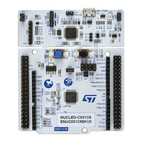
Nucleo-64 board
Brand:
ST
| Category:
Computer Hardware
| Size: 1 MB
Table of Contents
Figure 1. NUCLEO-C071RB Board Top View
1
1 Features
2
Table 1. Ordering Information
3
Table 2. Codification Explanation
3
2 Ordering Information
3
Codification
3
3 Development Environment
4
System Requirements
4
Development Toolchains
4
Demonstration Software
4
Table 3. ON/OFF Convention
5
4 Conventions
5
Table 4. Default Jumper Configuration
6
5 Quick Start
6
Getting Started
6
Figure 2. Hardware Block Diagram
7
PCB Layout
8
6 Hardware Layout and Configuration
7
Figure 3. Top Layout
8
Figure 4. Board Mechanical Drawing (in Millimeters)
9
Figure 5. USB Composite Device
10
Programming and Debugging the On-Board MCU Using the MIPI ® Debug Connector
11
Table 5. STDC14/MIPI10 Connector (CN4) (SWD Only)
11
External Power Supply Input
12
Power Supply and Power Selection
12
Table 6. Power Supply Capabilities
12
Power Supply Output
13
Programming/Debugging When the Power Supply Is Not from STLINK-V2EC (STLK)
13
HSE Clock Reference
14
LSE Clock Reference
14
OSC Clock Sources
14
VDD IDD Measurement
14
Leds
15
Reset Sources
15
Table 7. VCP Communication
15
Virtual COM Port (VCP)
15
Push-Buttons
16
Table 8. USB Type-C ® FS GPIO Configuration
16
USB Type-C ® FS Port
16
Jumper Configuration
17
Table 9. Jumper Configuration
17
Solder Bridge Configuration
18
Embedded STLINK-V2EC
10
Drivers
10
STLINK-V2EC Firmware Upgrade
10
Mechanical Drawing
9
Table 10. Solder Bridge Configuration and Settings
18
7 Connectors
19
ARDUINO ® uno V3
19
Table 11. ARDUINO ® Connectors on NUCLEO-C071RB
20
ST Morpho Connectors (CN7 and CN10)
21
ST STM32 Nucleo Application Note (28 pages)
Thermal management guidelines for applications
Brand:
ST
| Category:
Microcontrollers
| Size: 5 MB
Table of Contents
1 General Information
2
2 Thermal Systems Definitions and Basic Concepts
3
Thermal Systems Definitions
3
Thermal Systems Study
3
Figure 1. Analogy between Electrical and Thermal System Domains
3
Thermal Model of a Chip Carrier
4
Table 1. Thermal Parameters
4
Figure 2. Thermal Model of a Chip Carrier
4
3 STM32 Thermal Parameters
5
Ambient Temperature
5
Junction Temperature
5
Ambient Temperature Versus Junction Temperature
5
Case Temperature
6
Board Temperature
6
STM32 Thermal Parameters
6
Table 2. STM32 Thermal Resistances
6
4 Power Dissipation and Cooling Methods
7
Power Dissipation
7
Minimizing Power Consumption (Pdiss)
8
Power Dissipation Variation with Junction Temperature
8
Risk of Thermal Runaway
9
Figure 3. HDC (Heat Dissipation Capability)
9
Figure 4. HDC and Junction-Temperature-Dependent Dissipated Power (Case 1)
9
Figure 5. HDC and Junction-Temperature-Dependent Dissipated Power (Case 2)
10
Figure 6. HDC and Junction-Temperature-Dependent Dissipated Power (Case 3)
10
Figure 7. HDC and Junction-Temperature-Dependent Dissipated Power (Case 4)
10
5 Cooling
11
Power Dissipation Paths
11
Main Cooling Methods
11
Natural Convection
11
Forced Convection
11
Natural and Forced Convection Comparison
11
Figure 8. Power Dissipation Paths
11
Bottom Cooling - Host PCB Design
12
Host PCB Ground and Power Layout
12
Table 3. Natural and Forced Convection Comparison
12
Additional GND Areas on Outer Layers
13
Figure 9. Principle of Additional GND Areas and Vias to the GND Plane
13
6 Thermal Analysis Example
14
Evaluation Board with STM32MP157 MPU
14
STM32MP157 Power Dissipation
14
Figure 10. Stm32Mp157X-EV1
14
Table 4. STM32MP157 Power Dissipation Versus T
15
Figure 11. Junction-Temperature-Dependent Dissipated Power for STM32MP157
15
STM32MP157 Thermal Measurements at Tamb = 25 °C
16
Table 5. STM32MP157 Thermal Measurements at Tamb = 25 °C
16
Figure 12. STM32MP157 Thermal Measurements at Tamb = 25 °C
16
Figure 13. HDC at 25 °C and Junction-Temperature-Dependent Dissipated Power for STM32MP157
16
Table 6. Measurement Interpolation at Tamb = 85 °C for STM32MP157
17
Figure 14. HDC at 85 °C and Junction-Temperature-Dependent Dissipated Power for STM32MP157
17
Discovery Kit with STM32H747XI MCU
18
Figure 15. STM32H747I-DISCO
18
STM32H7 Power Dissipation
19
Table 7. STM32H747XI Power Dissipation Versus T
19
Figure 16. Junction-Temperature-Dependent Dissipated Power for STM32H7
20
Figure 17. STM32H747XI Thermal Measurements at Tamb = 25 °C
20
STM32H7 Thermal Measurements at Tamb = 25 °C
20
Table 8. STM32H7 Thermal Measurements at Tamb = 25 °C
20
Figure 18. HDC at 25 °C and Junction-Temperature-Dependent Dissipated Power for STM32H7
21
Figure 19. HDC at 85 °C and Junction-Temperature-Dependent Dissipated Power for STM32H7
21
Table 9. Measurement Interpolation at Tamb = 85 °C for STM32H7
22
ST STM32 Nucleo User Manual (24 pages)
Brand:
ST
| Category:
Microcontrollers
| Size: 0 MB
Table of Contents
Introduction
1
Table of Contents
2
STM32 (STEVAL-PCC012V1) and EVALST7570-1
5
Figure 1. EVALST7570 - Microcontroller Extension Connection
5
Figure 2. STEVAL-PCC012V1 - PLM Connector CN7
5
Table 1. Interconnection of Demonstration Boards EVALST7570 and STEVAL-PCC012V1
6
Figure 3. STEVAL-PCC012V1 - Board Settings by JP2 and JP3
6
Figure 4. Connectors Interconnection - 14-Pin STM32
6
Figure 5. Connectors Interconnection - 20-Pin ST7570
6
STM32 (STEVAL-PCC012V1) and EVALST7590-1
7
Figure 6. EVALST7590 - Microcontroller Extension Connector
7
Figure 7. EVALST7590 - Jumper Setup
7
Figure 8. STEVAL-PCC012V1 - PLM Connector CN7
7
Table 2. Interconnection of Demonstration Boards EVALST7590 and STEVAL-PCC012V1
8
Figure 9. Connectors Interconnection - 14-Pin STM32 and 14-Pin ST7590
8
Stm32 (Stm3210C-Eval) + Evalst7590-1
9
Table 3. Interconnection of STM3210C-EVAL and EVALST7590-1
9
Table 4. STM3210C-EVAL Jumper Position
9
Spear320 and EVALST7590-1
10
Table 5. Interconnection of Evalspear320 and EVALST7590-1
10
Figure 10. Spear320 and EVALST7590-1
10
Evalspear310 and EVALST7590-1 Via RS232
11
Figure 11. Evalspear310 and EVALST7590-1 Via RS232
11
Figure 12. STEVAL-PCC001V1
12
Spear3Xx and ST7570, ST7580, ST7590 Via USB
13
Figure 13. Evalspear3Xx and ST7570, ST7580, ST7590 Via USB
13
Evalspear320Hmi and ST7570, ST7580, ST7590 Via UART
14
Figure 14. Evalspear320Hmi and ST7570, ST7580, ST7590 Via UART
14
Figure 15. Evalspear320Hmi, Unified PLM Connector CN704 (ST7570/80/90)
14
Table 6. Evalspear320Hmi, Unified PLM Connector CN704 (ST7570/80/90)
15
Appendix Ahw Images
16
STM32 (STEVAL-PCC012V1) and EVALST7570-1
16
Figure 16. ST7570 and STEVAL-PCC012V1
16
STM32 (STEVAL-PCC012V1) and EVALST7590-1
17
STM32 (STM3210C-EVAL) and EVALST7590-1
17
Figure 17. ST7590 and STEVAL-PCC012V1
17
Figure 18. ST7590 and STM3210C-EVAL
17
Spear320 and EVALST7590-1
18
Spear310 and EVALST7590-1 Via RS232
18
Figure 19. Spear320 and EVALST7590-1
18
Figure 20. Spear310 and EVALST7590-1 Via RS232
18
Any Spear3Xx and ST7570, ST7580 or ST7590 Via USB
19
Figure 21. any Spear3Xx and ST7570, ST7580 or ST7590 Via USB
19
Evalspear320Hmi and ST7570, ST7580, ST7590 Via UART
20
Figure 22. Spear320Hmi and ST7570 Via the Unified Connector, UART
20
Appendix B Additional Schematics
21
Steval-Pcc001V1
21
Figure 23. STEVAL-PCC001V1 Schematic
21
Extension Connectors at Spear320Hmi Board
22
Figure 24. Spear320Hmi, CN701
22
Figure 25. Spear320Hmi, CN702
22
Appendix C Endnotes
23
Revision History
23
Document Revision History
23
ST STM32 Nucleo User Manual (25 pages)
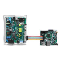
motor-control pack using the FOC algorithm for three-phase, low-voltage, and low‑current motor evaluation
Brand:
ST
| Category:
Computer Hardware
| Size: 5 MB
Table of Contents
Figure 1. P-NUCLEO-IHM03 Pack
1
Features
2
Ordering Information
3
Codification
3
Table 1. List of Available Products
3
Table 2. Nucleo Pack Codification Explanation
3
Table 3. Power Board Codification Explanation
3
Table 4. Nucleo Board Codification Explanation
4
Development Environment
5
System Requirements
5
Development Toolchains
5
Demonstration Software
5
Conventions
6
Table 5. ON/OFF Conventions
6
Getting Started (Basic User)
7
System Architecture
7
Figure 2. Four-Block Architecture of the P-NUCLEO-IHM03 Pack
7
Configure and Run the Motor Control from the STM32 Nucleo Motor-Control Pack
8
Figure 3. X-NUCLEO-IHM16M1 and NUCLEO-G431RB Assembled
8
Figure 4. Motor Connection with X-NUCLEO-IHM16M1
9
Figure 5. Power-Supply Connection for X-NUCLEO-IHM16M1
10
Hardware Settings
11
Table 6. Jumper Settings
11
Table 7. Screw Terminal Table
11
Table 8. Connector Description
11
Upload the Firmware Example
12
Figure 6. X-NUCLEO-IHM16M1 Connectors
12
Drag-And-Drop Procedure
13
Stm32Cubeprogrammer Tool
13
Figure 7. Stm32Cubeprogrammer Tool
13
Demonstration Usage
14
Figure 8. Stm32Cubeprogrammer Download
14
FOC Control Algorithm Settings (Advanced User)
15
References
16
Table 9. Stmicroelectronics Reference Documents
16
P-NUCLEO-IHM03 Nucleo Pack Product Information
17
Product Marking
17
P-NUCLEO-IHM03 Product History
18
Table 10. Product History
18
Board Revision History
19
Table 11. Board Revision History
19
Federal Communications Commission (FCC) and ISED Canada Compliance
20
Statements
20
FCC Compliance Statement
20
ISED Compliance Statement
20
Revision History
21
Table 12. Document Revision History
21
Table of Contents
22
List of Tables
23
List of Figures
24
ST STM32 Nucleo Application Note (18 pages)
ADC modes and their applications
Brand:
ST
| Category:
Microcontrollers
| Size: 0 MB
Table of Contents
Table of Contents
2
Figure 1. Single-Channel, Single Conversion Mode
5
Independent Modes
5
Figure 2. ADC Sequencer Converting 7 Channels with Different Configured Sampling
5
Multichannel (Scan), Single Conversion Mode
5
Single-Channel, Single Conversion Mode
5
Description
5
Example of Application
5
Example of Application
6
Single-Channel Continuous Conversion Mode
6
Description
6
Figure 3. Multichannel, Single Conversion Mode
6
Figure 4. Single-Channel, Continuous Conversion Mode
6
Example of Applications
7
Figure 5. Multichannel, Continuous Conversion Mode
7
Example of Application
8
Figure 6. Injected Conversion Mode
8
Injected Conversion Mode
7
Multichannel (Scan) Continuous Conversion Mode
7
Description
7
Example of Application
7
Dual Modes
9
Dual Regular Simultaneous Mode
9
Description
9
Example of Application
9
Figure 7. Dual Regular Simultaneous Mode
9
Dual Fast Interleaved Mode
10
Description
10
Figure 8. Simultaneous Measurement of Voltage and Current
10
Example of Application
11
Dual Slow Interleaved Mode
11
Description
11
Figure 9. Dual Fast Interleaved Mode
11
Example of Application
12
Figure 10. Dual Slow Interleaved Mode
12
Dual Alternate Trigger Mode
13
Description
13
Example of Application
13
Figure 11. Dual Alternate Trigger Mode
13
Dual Combined Regular/Injected Simultaneous Mode
14
Description
14
Example of Application
14
Dual Combined: Injected Simultaneous + Interleaved Mode
14
Figure 12. Dual Combined Regular/Injected Simultaneous Mode
14
Example of Application
15
Figure 13. Dual Combined: Injected Simultaneous + Interleaved Mode
15
Figure 14. UPS System
15
3 Conclusion
16
4 Revision History
17
ST STM32 Nucleo User Manual (33 pages)
based camera with ZigBee connectivity
Brand:
ST
| Category:
Computer Hardware
| Size: 2 MB
Table of Contents
Table of Contents
2
Getting Started
4
Package
4
Hardware Setup
4
Setting the Camera Unit
4
Setting the Monitoring Unit
5
Figure 1. Camera Unit
5
Figure 2. Monitoring Unit
5
Hardware Layout
6
Figure 3. STEVAL-IFV001V1 Front View
6
Figure 4. STEVAL-IFV001V1 Rear View
6
System Overview
7
System Architecture Description
7
Figure 5. System Architecture
7
Running the System
9
Powering up
9
Schematics of STEVAL-IFV001V1
10
Camera Unit
10
Figure 6. Microcontroller Schematic
10
Figure 7. Connector Schematic
11
Figure 8. Camera Zigbee Schematic
12
Figure 9. Battery Schematic
13
Bill of Material of STEVAL-IFV001V1
14
Schematics of the STEVAL-CCM003V1
19
Figure 10. Microcontroller Schematic
19
Figure 11. Bluetooth Schematic
20
Figure 12. TFT, Touch, Temperature and JTAG Schematics
21
Figure 13. Micro SD and Zigbee Schematics
22
Figure 14. Power Schematic
23
Figure 15. MEMS and USB Schematics
24
Figure 16. Touch Schematic
25
Bill of Material of the STEVAL-CCM003V1
26
Revision History
32
ST STM32 Nucleo User Manual (27 pages)
Motor-control pack using the FOC algorithm for three-phase, low-voltage, and low-current motor evaluation
Brand:
ST
| Category:
Control Unit
| Size: 21 MB
Table of Contents
1 Features
2
2 Ordering Information
3
Product Marking
3
Codification
3
3 Development Environment
4
System Requirements
4
Development Toolchains
4
Demonstration Software
4
4 Getting Started (Basic User)
5
System Architecture
5
Figure 2. Four-Block Architecture of the P-NUCLEO-IHM03 Pack
5
Configure and Run the Motor Control from the STM32 Nucleo Motor-Control Pack
6
Figure 3. X-NUCLEO-IHM16M1 and NUCLEO-G431RB Assembled
6
Figure 4. Motor Connection with X-NUCLEO-IHM16M1
7
Hardware Settings
9
Upload the Firmware Example
10
Drag-And-Drop Procedure
11
Stm32Cubeprogrammer Tool
11
Demonstration Usage
12
Figure 8. Stm32Cubeprogrammer Download
12
5 FOC Control Algorithm Settings (Advanced User)
13
6 Electrical Schematics
14
Figure 9. X-NUCLEO-IHM16M1 Motor Driver Connections
14
Figure 10. X-NUCLEO-IHM16M1 Current-Sensing Conditioning Circuit
14
Figure 11. X-NUCLEO-IHM16M1 Sensors and Shunt Resistor Circuit
14
Figure 12. X-NUCLEO-IHM16M1 L6230 Driver and BEMF Detection Circuit
14
Figure 13. X-NUCLEO-IHM16M1 MCU Pin Assignment
14
7 References
20
Appendix A Federal Communications Commission (FCC) and Industry Canada (IC)
21
Compliance Statements
21
FCC Compliance Statement
21
IC Compliance Statement
21
Revision History
23
Table of Contents
24
Contents
24
List of Tables
25
List of Figures
26
ST STM32 Nucleo User Manual (22 pages)
Discovery pack for LTE IoT cellular to cloud
Brand:
ST
| Category:
Computer Hardware
| Size: 0 MB
Table of Contents
Figure 1. P-L496G-CELL02 (Top View)
1
Table of Contents
2
Features
6
Ordering Information
7
Table 1. Ordering Information
7
Development Environment
8
System Requirements
8
Development Toolchains
8
Conventions
9
Table 2. ON/OFF Conventions
9
Hardware Layout and Configuration
10
Board Layouts
10
Figure 2. Main Board and Expansion LTE Iot Modem Top View
10
Cellular Stmod+ Expansion Board
11
Table 3. Stmod+ Connector Pin Description
11
Figure 3. Main Board and Expansion LTE Iot Modem Bottom View
11
Modem Power Supply and Reset
12
SIM Selection
12
Modem Firmware Update
12
Embedded ST_LINK/V2-1
13
Drivers
13
Main Board Power Supply
13
Power Supply Sources
13
Figure 4. USB Composite Device Driver Installation
13
Main Board Reset Sources
14
Main Board Boot Options
14
Table 4. Boot Settings
14
P-L496G-CELL02 Troubleshooting
16
P-L496G-CELL02 Product Information
17
Product Marking
17
P-L496G-CELL02 Product History
18
Board Revision History
18
Table 5. Product History
18
Table 6. Board Revision History
18
Federal Communications Commission (FCC) and ISED Canada (IC) Compliance Statements
19
FCC Compliance Statement
19
ISED Compliance Statement
20
Table 7. Document Revision History
21
ST STM32 Nucleo User Manual (22 pages)
Nucleo board software development tools
Brand:
ST
| Category:
Motherboard
| Size: 0 MB
Table of Contents
Figure 1. Nucleo Development Tools
1
Table of Contents
2
System Requirements
4
Figure 2. Connector CN1 for Nucleo 144 Board
4
Figure 3. Connector CN1 for Nucleo 64 Board
5
Figure 4. Connector CN1 for Nucleo 32 Board
5
Ides Supporting STM32 Families
6
ST-LINK/V2-1 Installation
7
Firmware Package
8
Executing and Debugging Firmware Using Software Toolchains
8
Figure 5. Package Contents
8
EWARM Toolchain
9
Figure 6. IAR Embedded Workbench IDE
9
Figure 7. EWARM Project Successfully Compiled
9
Figure 8. Download and Debug Button
10
Figure 9. IAR Embedded Workbench Debugger Screen
10
MDK-ARM Toolchain
11
Figure 10. Go Button
11
Figure 11. Μvision5 IDE
11
Figure 12. MDK-ARM Project Successfully Compiled
12
Figure 13. Start/Stop Debug Session Button
12
Figure 14. MDK-ARM Debugger Screen
13
Figure 15. Run Button
13
Truestudio Toolchain
14
Figure 16. Truestudio Workspace Launcher Dialog Box
14
Figure 17. Atollic Truestudio Import Source Select Dialog Box
15
Figure 18. Atollic Truestudio Import Projects Dialog Box
15
Figure 19. Truestudio Project Successfully Compiled
16
Figure 20. Truestudio Debug Window
17
SW4STM32 Toolchain
18
Figure 21. SW4STM32 Workspace Launcher Dialog Box
18
Figure 22. SW4STM32 Import Source Select Dialog Box
18
Figure 23. SW4STM32 Import Projects Dialog Box
19
Figure 24. SW4STM32 Project Successfully Compiled
19
Figure 25. SW4STM32 Debug Window
20
Revision History
21
ST STM32 Nucleo User Manual (30 pages)
Brand:
ST
| Category:
Computer Hardware
| Size: 1 MB
Table of Contents
Table of Contents
2
Set up Hardware
3
Use STM32 Motor Control Workbench to Configure the Library and Generate the Code
3
Create New Project for ST STEVAL-SPIN3201 Board
3
Create New Project for ST STEVAL-SPIN3202 Board
4
Create a New Project for STSPIN32F0/A Mounted on a Custom Board
6
Customize Parameters for Application Needs
9
Motor Parameters
9
Power Stage Parameters
10
Drive Management Parameters
13
Control Stage Parameters
17
Create the Library and Download the Firmware
23
Generation of the Source Code
23
Using STSW-SPIN3201
25
Compile and Download the Firmware
26
Control the Motor
27
Revision History
29
ST STM32 Nucleo User Manual (43 pages)
STM32 boards
Brand:
ST
| Category:
Motherboard
| Size: 1 MB
ST STM32 Nucleo Application Note (16 pages)
Getting started with Sensor expansion board
Brand:
ST
| Category:
Motherboard
| Size: 1 MB
Table of Contents
Table of Contents
2
Acronyms and Abbreviations
3
Getting Started
4
Hardware Description
4
STM32F401RE Nucleo
4
Sensor Expansion Board
4
Software Description
5
Stm32Cube
6
Firmware for STM32 Nucleo with X-NUCLEO-IKS01A1 Expansion
6
Board
6
Hardware and Software Setup
6
Hardware Setup
6
Software Setup
6
System Setup Guide
7
Software Overview
8
Software Architecture
8
Stm32Cube HAL
8
Board Support Package (BSP)
9
Guide for Writing Applications
10
Relevant Apis for Sensor Applications
10
Initialization
10
Application Description
11
Using the Sensors_Datalog Application
12
Revision History
15
ST STM32 Nucleo User Manual (18 pages)
TCPM Application
Brand:
ST
| Category:
Microcontrollers
| Size: 0 MB
Table of Contents
Table of Contents
2
1 Overview
5
Acronyms and Abbreviations
5
References
6
2 USB-C™ PD Architecture
7
Architecture Overview
7
Figure 1. USB Power Delivery Architecture
7
Specific Case of TCPM/TCPC Architecture
8
Figure 2. USB Type-C™ Port Manager to USB Type-C™ Port Controller Interface
8
Figure 3. ST Firmware Architecture
9
3 USB-PD ST Application Setup
11
4 Examples Description
12
USB-PD DRP (TCPM/TCPC Architecture)
12
Example Setup
12
Figure 4. Project Structure
12
Application Description
13
Library Initialization
13
TCPM API Description
14
5 Memory Footprint of the EVAL_FUSB307_DRP Example
15
6 Frequently Asked Questions (Faqs)
16
7 Revision History
17
ST STM32 Nucleo Quick Start Manual (31 pages)
Brand:
ST
| Category:
Motherboard
| Size: 2 MB
Table of Contents
Hardware and Software Overview
3
Hardware Overview
4
Setup Overview
14
Demo Examples
21
ST STM32 Nucleo User Manual (14 pages)
How to use expansion board based on the STSAFE-A110 secure element
Brand:
ST
| Category:
Computer Hardware
| Size: 0 MB
Table of Contents
1 Getting Started
2
Hardware Requirements
2
System Requirements
2
2 Hardware Description
3
Jumpers and Solder Bridges
3
Connector
3
3 STM32L4 Series Microcontroller Software
4
4 Schematic Diagrams
5
5 Bill of Materials
8
Revision History
10
Advertisement
Related Products
ST STM32F31xx
ST STM32F30xx
ST STM32F030
ST STM32F2 Series
ST STM32F413 Series
ST STM32F423 Series
ST STM32L4x6
st STM32F429I-DISCO
st STM32F429 Series
st STM32F4DISCOVERY
ST Categories
Motherboard
Computer Hardware
Microcontrollers
Control Unit
Controller
More ST Manuals
Login
Sign In
OR
Sign in with Facebook
Sign in with Google
Upload manual
Upload from disk
Upload from URL