ST STM32 Application Note
Thermal management guidelines for applications
Hide thumbs
Also See for STM32:
- User manual (85 pages) ,
- Application note (49 pages) ,
- Quick start manual (31 pages)
Table of Contents
Advertisement
Quick Links
AN5036
Application note
Thermal management guidelines for STM32 applications
Introduction
This document describes the thermal management guidelines for applications based on STM32 microcontrollers or
microprocessors, that, like any silicon-based integrated circuits, have well-defined storage and operating temperature ranges.
Only the STM32 operating temperature ranges defined in product datasheets are considered: the maximum operating
temperature range and the product operating temperature range. The maximum operating temperature range defines the
threshold temperature beyond which there is a high probability of permanent damage to the device. The operating temperature
range defines the threshold temperature beyond which the electrical parameters are not guaranteed to be within the
specification.
The STM32 maximum specified operating range is referenced to the junction temperature, whereas the operating temperature
range is referenced to the ambient temperature and possibly also to the junction temperature.
Specifying these operating temperature ranges by reference to the ambient temperature or to the junction temperature, is a
common practice in the semiconductor industry. Depending on the device and its power consumption, semiconductor vendors
use either the ambient temperature or the junction temperature for the product operating temperature range specification.
AN5036 - Rev 3 - April 2019
www.st.com
For further information contact your local STMicroelectronics sales office.
Advertisement
Table of Contents

Subscribe to Our Youtube Channel
Related Manuals for ST STM32


Summary of Contents for ST STM32
- Page 1 The STM32 maximum specified operating range is referenced to the junction temperature, whereas the operating temperature range is referenced to the ambient temperature and possibly also to the junction temperature.
-
Page 2: General Information
AN5036 General information General information ® This document applies to STM32 Arm -based devices. Note: Arm is a registered trademark of Arm Limited (or its subsidiaries) in the US and/or elsewhere. AN5036 - Rev 3 page 2/28... -
Page 3: Thermal Systems Definitions And Basic Concepts
AN5036 Thermal systems definitions and basic concepts Thermal systems definitions and basic concepts This section details basic definitions and concepts related to thermal systems, as applied to silicon-based integrated circuits (ICs). Thermal systems definitions Heat: The amount of energy exchanged between two different bodies spontaneously under the effect of their different temperatures. -
Page 4: Thermal Model Of A Chip Carrier
Thermal model of a chip carrier Thermal model of a chip carrier A simplified thermal model for an LQFP-packaged STM32 product is provided in the figure below. All surface temperatures and thermal resistance (as defined by the JEDEC EIA/JESD 51-X standards) are depicted. -
Page 5: Stm32 Thermal Parameters
Ambient temperature versus junction temperature Both ambient temperature and junction temperature to specify the thermal performance of STM32 devices. For many STM32 products, only the maximum ambient temperature is specified as their thermal performance limit. The junction temperature is also sometimes added. -
Page 6: Case Temperature
5 % is dissipated through the package. STM32 thermal parameters Most of STM32 datasheets give only Theta-JA thermal resistance, but some specify also Theta-JC and Theta-JB, defined in the table below. Table 2. -
Page 7: Power Dissipation And Cooling Methods
AN5036 Power dissipation and cooling methods Power dissipation and cooling methods This section provides recommendations for efficient thermal analysis on STM32 applications, focusing on the following points: • Power dissipation and its variation with various factors named PVTA (process, voltage, (junction) temperature and activity) •... -
Page 8: Minimizing Power Consumption (Pdiss)
Minimizing power consumption (Pdiss) To reduce the power consumption, the first action is to reduce the supply voltage. Some STM32 devices offer a multi-power domain architecture that allows the different power domains to be set in low-power mode to optimize the power efficiency (see the product datasheets for more details). -
Page 9: Risk Of Thermal Runaway
AN5036 Risk of thermal runaway Risk of thermal runaway The cooling system of a design is characterized by the junction-to-room temperature thermal resistance, Theta_j_room. This thermal resistance gives the capability to dissipate power in the design while limiting the junction temperature. -
Page 10: Figure 5. Hdc And Junction-Temperature-Dependent Dissipated Power (Case 2)
AN5036 Risk of thermal runaway Case 2 The figure below shows the effect of an increased room temperature (without changing any other factors). Figure 5. HDC and junction-temperature-dependent dissipated power (case 2) Power No intersection point Pdiss Thermal runaway 125 °c room room_max Case 3... -
Page 11: Cooling
AN5036 Cooling Cooling Power dissipation paths The power dissipated by the die is extracted along the two following main paths: • Top side: power dissipated from the top side, (by a heat sink through an optional TIM, thermal interface material). •... -
Page 12: Bottom Cooling - Host Pcb Design
AN5036 Bottom cooling - host PCB design 5.2.3 Natural and forced convection comparison The table below details the main comparison factors between the natural and forced convection. Table 3. Natural and forced convection comparison Comparison factors Natural convection Forced convection Medium to high Cooling efficiency Small... -
Page 13: Additional Gnd Areas On Outer Layers
AN5036 Bottom cooling - host PCB design 5.3.2 Additional GND areas on outer layers On the outer layers, some GND areas can be added wherever functional tracks are absent. Connect these areas to GND by a network of vias wherever possible. These GND areas help in heat spreading and dissipation along the board. -
Page 14: Thermal Analysis Example
AN5036 Thermal analysis example Thermal analysis example This section shows an example of thermal analysis performed on evaluation boards with STM32MP157 MPUs. This analysis provides answers to the following questions (at maximum ambient temperature 85 °C): • How much is the power dissipation, taking into account of the leakage? •... -
Page 15: Table 4. Stm32Mp157 Power Dissipation Versus T
AN5036 Evaluation board with STM32MP157 MPU 6.1.1 STM32MP157 power dissipation As stated in Section 3 , the dissipated power varies with Tj. The power consumption in this example is measured for different Tj values (see the table and the figure below). Table 4. -
Page 16: Stm32Mp157 Thermal Measurements At Tamb = 25 °C
AN5036 Evaluation board with STM32MP157 MPU 6.1.2 STM32MP157 thermal measurements at Tamb = 25 °C The figures and table below detail the thermal measurements performed at Tamb = 25 °C. Figure 12. STM32MP157 thermal measurements at Tamb = 25 °C Table 5. -
Page 17: Table 6. Measurement Interpolation At Tamb = 85 °C For Stm32Mp157
AN5036 Evaluation board with STM32MP157 MPU Once the HDC of the design is defined (by measurement at 25 °C), and assuming that this HDC is constant at 25°C and 85 °C, the operating point of the design at 85 °C is given by translating the HDC at 85 °C as shown in the figure and table below. -
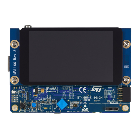
Page 18: Discovery Kit With Stm32H747Xi Mcu
AN5036 Discovery kit with STM32H747XI MCU Discovery kit with STM32H747XI MCU This thermal analysis has been done on a Discovery kit with a STM32H747XI device (STM32H747I-DISCO), without casing (see the figure below). Figure 15. STM32H747I-DISCO This picture is not contractual. The test case is the following: •... -
Page 19: Stm32H7 Power Dissipation
AN5036 Discovery kit with STM32H747XI MCU 6.2.1 STM32H7 power dissipation As stated in Section 3 , the dissipated power varies with T . The power consumption in this example is measured for different T values (see the table and the figure below). Table 7. -
Page 20: Stm32H7 Thermal Measurements At Tamb = 25 °C
AN5036 Discovery kit with STM32H747XI MCU Figure 16. Junction-temperature-dependent dissipated power for STM32H7 Discovery kit STM32H747XI 6.2.2 STM32H7 thermal measurements at Tamb = 25 °C The figures and table below detail the thermal measurements performed at Tamb = 25 °C. Figure 17. -
Page 21: Figure 18. Hdc At 25 °C And Junction-Temperature-Dependent Dissipated Power For Stm32H7
AN5036 Discovery kit with STM32H747XI MCU Figure 18. HDC at 25 °C and junction-temperature-dependent dissipated power for STM32H7 Discovery kit at Tamb = 25 °C Operating point @Tamb = 25°C (Ptot = 1975 mW, Tj = 46.9 °C) For P = 0 mW, Tj = Tamb = 25°C (Ptot = 0 mw) Once the HDC of the design is defined (by measurement at 25 °C), and assuming that this HDC is constant at 25°C and 85 °C, the operating point of the design at 85 °C is given by translating the HDC at 85 °C as shown in... -
Page 22: Table 9. Measurement Interpolation At Tamb = 85 °C For Stm32H7
AN5036 Discovery kit with STM32H747XI MCU Table 9. Measurement interpolation at Tamb = 85 °C for STM32H7 Parameter Value 119 °C Ptot 3050 mW In conclusion, the STM32H7 device is safe, with no thermal runaway and T remaining < 125 °C. AN5036 - Rev 3 page 22/28... -
Page 23: Revision History
Section 3.3 Ambient temperature versus junction temperature • Section 3.5 Board temperature 4-Mar-2019 • Section 4 Power dissipation and cooling methods Added: • Section 3.6 STM32 thermal parameters • Section 6 Thermal analysis example Updated Section 3.6 STM32 thermal parameters. 19-Apr-2019 Added Section 6.2 Discovery kit with STM32H747XI... -
Page 24: Table Of Contents
STM32 thermal parameters ........ - Page 25 AN5036 Contents 6.1.2 STM32MP157 thermal measurements at Tamb = 25 °C ......16 Discovery kit with STM32H747XI MCU ......... . . 17 6.2.1 STM32H7 power dissipation .
- Page 26 STM32 thermal resistances ........
- Page 27 AN5036 List of figures List of figures Figure 1. Analogy between electrical and thermal system domains ........3 Figure 2.
- Page 28 ST’s terms and conditions of sale in place at the time of order acknowledgement. Purchasers are solely responsible for the choice, selection, and use of ST products and ST assumes no liability for application assistance or the design of Purchasers’...
Need help?
Do you have a question about the STM32 and is the answer not in the manual?
Questions and answers