ST STM32 User Manual
Usb demonstration kit
Hide thumbs
Also See for STM32:
- User manual (85 pages) ,
- Application note (49 pages) ,
- Quick start manual (31 pages)
Table of Contents
Advertisement
Quick Links
1
Introduction
This user manual describes hardware and software of the STMicroelectronics™ STM32™
performance line USB demonstration kit based on the STM32F103 microcontroller and the
2
I
S TS4657 audio digital to analog converter (decoder). The audio output can be
implemented either with the TS4962 driven onboard speaker which output is also available
on the onboard mono jack connector, or through TS2012 stereo audio amplifier which can
drive external speakers. Both audio amplifiers are Class-D. The audio input is available with
an onboard microphone which is connected through TS472 microphone preamplifier to the
ADC input of the microcontroller. To facilitate the reuse of the boards, the controller and the
audio card can be disconnected, and used separately for other purposes.
This demonstration kit primarily offers a USB interface operating either under USB Audio
Device Class for audio streaming, or Device Firmware Upgrade class (DFU) for application
reprogramming through the USB. All design information are included in the kit and can be
reused for a new development. The demonstration kit allows a quick evaluation of
STMicroelectronics low-voltage audio components in Human machine interface (HMI) audio
input/output, portable audio equipment, and simple PC USB demonstration kit applications.
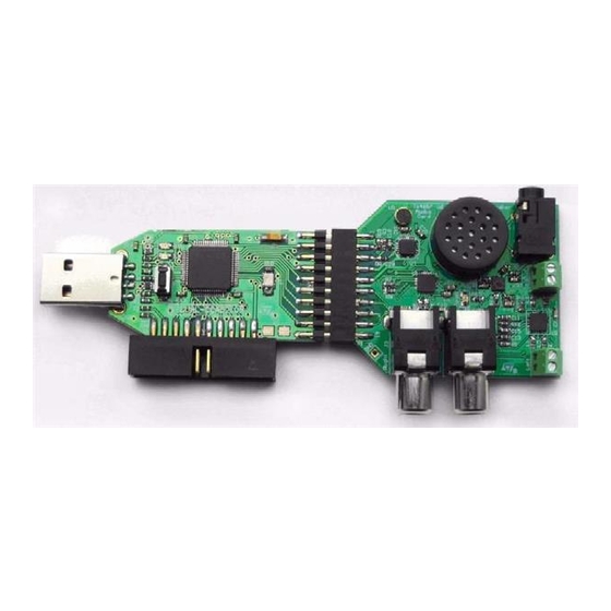
Figure 1.
STM32F103 USB demonstration kit - top view
August 2009
www.BDTIC.com/ST
Getting started with STEVAL-CCA021V1,
STM32 performance line USB demonstration kit
Doc ID 15867 Rev 1
UM0722
User manual
1/46
www.st.com
Advertisement
Table of Contents

Related Manuals for ST STM32


Summary of Contents for ST STM32
-
Page 1: Figure 1. Stm32F103 Usb Demonstration Kit - Top View
STM32 performance line USB demonstration kit Introduction This user manual describes hardware and software of the STMicroelectronics™ STM32™ performance line USB demonstration kit based on the STM32F103 microcontroller and the S TS4657 audio digital to analog converter (decoder). The audio output can be... -
Page 2: Table Of Contents
Boards layout ..........11 STM32 controller board layout ....... . . 11 TS4657 audio card layout . - Page 3 10.3 B1 button on the STM32 controller board ......25 Demonstration kit software ........26 11.1...
- Page 4 List of tables Table 1. S audio connector pins description of the STM32 controller board ....15 Table 2. JTAG connector pins description ..........16 Table 3.
- Page 5 Microphone record-replay mode system setup........14 Figure 11. S audio connector of the STM32 controller board - schematic ....15 Figure 12.
-
Page 6: Description
Description UM0722 Description The STM32 performance line USB demonstration kit is designed to demonstrate several STMicroelectronics products: ● The TS4657 is a stereo DAC that integrates a high-performance audio line driver capable of generating a 2.2 V output level from a single 3.0 to 5.5 V supply. One single supply is sufficient for the digital and analog parts of the circuit, thus eliminating the need for external regulators. -
Page 7: Boards Key Features
● Onboard microphone and small speaker ● Connectors summary – 20-pin dual line header for connection to the STM32 performance line controller board – Two RCA connectors available as TS4657 line outputs – Mono jack connector available as TS4962 amplifier output –... -
Page 8: General System Description
STM32F103 controller board. Figure 2. STM32F103 USB demonstration kit - block diagram Stereo lineout Connectors TS4657 TS2012 external speakers I 2 S STM32 Onboard TS4962 speaker Digital control Mono jack Analog external speaker On board TS472... -
Page 9: Getting Started
Getting started Getting started System requirements ® In order to use the STM32 performance line USB demonstration kit with the Microsoft ® Windows operating system, a recent version of Windows, such as Windows XP, Windows 98, Windows Millennium or Windows 2000 must be installed on your PC. -
Page 10: Figure 3. Device Manager Window - New Usb Audio Device
Getting started UM0722 Warning: Do not place the STM32 performance line USB demonstration kit speaker close to your ears. It might harm your hearing if the card is set to deliver the maximum output power. Figure 3. Device manager window - new USB audio device... -
Page 11: Boards Layout
UM0722 Boards layout Boards layout STM32 controller board layout Figure 4. STM32 controller board layout TS4657 audio card layout Figure 5. TS4657 audio card board layout Doc ID 15867 Rev 1 11/46 www.BDTIC.com/ST... -
Page 12: System Setup
7.1.1 Onboard speaker configuration This is the default configuration after the STM32 performance line USB demonstration kit is plugged into the available PC USB port. The green LED LD2 switches on when the demonstration kit is in operating mode. The PC automatically detects the new demonstration kit and all audio outputs are automatically redirected to the new sound device by Windows. -
Page 13: External Amplified Stereo Output Configuration
Lineout output system setup Microphone record-replay mode The onboard microphone can be used only in record-replay mode. To change the operating mode from PC USB demonstration kit to record-replay mode, press B1 for approximately 1 s. Doc ID 15867 Rev 1 13/46 www.BDTIC.com/ST... -
Page 14: Figure 10. Microphone Record-Replay Mode System Setup
System setup UM0722 In this mode the STM32 performance line USB demonstration kit records 5 s long audio sample and than plays it back through any mean (speaker) presented in the above chapter. In this mode, LD2 blinks at a fast rate when the demonstration kit is recording, and at a slower rate when the acquired record is being played back. -
Page 15: Connectors Of The Stm32 Performance Line Controller Board
The P2 connector is used to interconnect the STM32F103 controller board and the TS4657 audio card. This connector is functionally compatible with the P1 connector described in Section 9.1. Table 1. S audio connector pins description of the STM32 controller board Signal Signal Signal Signal... -
Page 16: Table 2. Jtag Connector Pins Description
Connectors of the STM32 performance line controller board UM0722 choice of development tools on the market supporting microcontroller Flash memory programming and application debugging. Figure 12. JTAG connector 4 6 8 10 12 14 16 18 20 3 5 7 9... -
Page 17: Connectors And Functionality Of The Ts4657 Audio Card
Mono jack connector J4 and the onboard speaker U6 The mono jack audio connector J4 is connected to the output of the TS4962 Class-D mono audio amplifier U3. The amplifier drives either the onboard speaker or the J4 mono jack Doc ID 15867 Rev 1 17/46 www.BDTIC.com/ST... -
Page 18: Ts2012 Stereo Output Terminal Connectors P2, P3
150 KΩ BLM18EG221SN1 100 pF Oscillator KSSG1708 Speaker ST: TS4962IQT AM00484 TS2012 stereo output terminal connectors P2, P3 The TS2012 stereo Class-D amplifier output is available outside the board through the onboard terminal connectors P2 and P3. Table 5. TS2012 stereo output terminal connectors P2, P3... -
Page 19: Ts4657 Stereo Dac Output Audio Rca Connectors J1, J3
UM0722 Connectors and functionality of the TS4657 audio card Figure 16. TS2012 stereo output terminal connectors P2, P3 100 pF ST: TS2012IQT BLM18EG221SN1 AV CC PV CC PV CC L OUT+ L IN + Gain L IN– Terminal block select... -
Page 20: Microphone Functionality
The preamplifier output is available on the I S audio connector P1 and is connected also to the ADC input pin of the STM32 MCU on the controller board. The microphone unit U5 is supplied from the TS472 preamplifier 2.0 V bias pin. R11, R12 (1 KΩ) resistors are polarizing resistors for biasing of the microphone. -
Page 21: Ts4657 Stereo Audio Dac Functionality
68 Ω Bias 2.0 V GNDA GNDA 1 µF STBY GNDA ST: TS472IQT MICRO_SHDN GNDA 10 KΩ GNDA Microphone preamplifier AM00487 TS4657 stereo audio DAC functionality The TS4657 is a stereo digital to analog converter. It is a 16-bit multi-bit sigma delta DAC operating at 256 x audio sample rate with over sampling digital interpolation filters. -
Page 22: Ts4962 Mono Class-D Power Amplifier Functionality
L5, L6, C32, C33 filters increase the EMI when an external speaker is connected through long cables. The amplifier is powered from +5 V coming from the controller board. 22/46 Doc ID 15867 Rev 1 www.BDTIC.com/ST... -
Page 23: Ts2012 Stereo Class-D Power Amplifier Functionality
1.35 W into a 8 Ω load at 5 V per channel. The device has four different gain settings utilizing two discrete pins: G0 and G1. These pins are controlled by STM32 MCU in the firmware. The gain is set to the minimal value by default thanks to the internal weak pull down resistors. -
Page 24: Figure 21. Ts2012 Stereo Class-D Amplifier Functionality
Figure 21. TS2012 stereo Class-D amplifier functionality 1 µF 1 µF 100 nF GND GND GND Stereo Class-D amplifier 5 V 5 V Gain control 100 pF ST: TS2012IQT 10 KΩ 10 KΩ PV CC PV CC L OUT+ BLM18EG221SN1 L IN + Gain L IN –... -
Page 25: Leds And Buttons
LEDs and buttons 10.1 LED indicators on the STM32 controller board The green LED (LD2) indicates that the demonstration kit is in operating mode. When it is switched on continuously, the PC USB demonstration kit is active; when it flashes, the card operates in the record-replay. -
Page 26: Demonstration Kit Software
Main program/Code Flash, data Flash/EEPROM, or any other memory connected to the microcontroller including serial I C or SPI Flash memories). The STM32 performance line USB demonstration kit features DFU capability used to program the internal Flash memory. Refer to the UM0412, Getting started with DfuSe USB device firmware upgrade STMicroelectronics extension (available online from: www.st.com/mcu), for more details on... -
Page 27: Pc Usb Demonstration Kit And Record-Replay Applications
The code provides a demonstration of the correct method for configuring an isochronous endpoint, receiving or transmitting data from/to the host and also shows how to use the data in a real-time application. Doc ID 15867 Rev 1 27/46 www.BDTIC.com/ST... -
Page 28: Record-Replay Application
S peripheral. For further details on usage of USB-FS-device firmware library for Audio Device Class purposes, please refer to UM0424, STM32F10xxx USB-FS-device development kit available online from www.st.com. 11.3.2 Record-replay application In the second mode of operation has the demonstration application task to capture vicinity... -
Page 29: Updating Demonstration Application In The Demonstration Kit
Demonstration kit software 11.4 Updating demonstration application in the demonstration kit For the STM32 the DFU mode is entered after an MCU reset if: ● The DFU mode is forced by the user: the user presses the key push-button during a reset (while he is attaching the evaluation dongle to the USB). -
Page 30: Test Measurement Of The Audio Signal
Test measurement of the audio signal Figure 22. Typical I S waveform Transmission Reception 16-bit LSB MSB Channel left Channel right ai17174 Figure 23. TS4657 output versus the I S input (10 kHz signal reconstruction) 30/46 Doc ID 15867 Rev 1 www.BDTIC.com/ST... -
Page 31: Figure 25. Typical Output From The Class-D Amplifiers
UM0722 Test measurement of the audio signal Figure 24. TS4657 output versus the I S input (10 kHz signal reconstruction) - detail Figure 25. Typical output from the Class-D amplifiers Doc ID 15867 Rev 1 31/46 www.BDTIC.com/ST... -
Page 32: Addendum
GME 960-023 LD2 D0805B 1 GM Electronic 960-023 35/130° Header, 10-pin, dual BL220G HDR2X10 S 1 GM Electronic 832-070 row, side mounting R1, R2, R6, Resistor 10 KΩ R9, R10, 0603 6 GM Electronic 901-399 32/46 Doc ID 15867 Rev 1 www.BDTIC.com/ST... - Page 33 0603 1 GM Electronic 901-396 470 Ω Resistor 0603 1 GM Electronic 901-495 220 Ω Resistor 0603 1 GM Electronic 901-491 STM32 ARM-based 32-bit MCU STM32F103RE LQFP64_N 1 STMicroelectronics STM32F103RET6 with 512 KB Flash, 64-pin LQFP Stabilizator LD3985XX33 U2 SOT23-5L...
- Page 34 901-502 Resistor 150 kΩ R14, R16 [0603] 2 GM Electronic 901-633 68 Ω Resistor [0603] 1 GM Electronic 901-408 Single supply stereo digital ST: TS4657IQT U1 QFN20_TS4657 1 STMicroelectronics TS4657IQT audio line driver 34/46 Doc ID 15867 Rev 1 www.BDTIC.com/ST...
- Page 35 Supplier order Description Comment Designator Footprint Supplier name Note code Filter-free stereo 2 x 2.8 W ST: TS2012IQT U2 QFN20 - TS2012 1 STMicroelectronics TS2012IQT Class-D audio power amplifier 2.8 W filter- free mono Class-D ST: TS4962IQT U3 DFN8 - TS4962...
-
Page 36: Appendix Bstm32F103 Controller Board
STM32F103 controller board UM0722 Appendix B STM32F103 controller board Figure 26. STM32F103 controller board - top overlay Figure 27. STM32F103 controller board - bottom overlay 36/46 Doc ID 15867 Rev 1 www.BDTIC.com/ST... -
Page 37: Figure 28. Ts4657 Audio Card - Top Layer
UM0722 STM32F103 controller board Figure 28. TS4657 audio card - top layer Figure 29. TS4657 audio card - bottom layer Doc ID 15867 Rev 1 37/46 www.BDTIC.com/ST... -
Page 38: Appendix Cts4657 Audio Card - Artwork Prints
TS4657 audio card - artwork prints UM0722 Appendix C TS4657 audio card - artwork prints Figure 30. TS4657 audio card - top overlay Figure 31. TS4657 audio card - bottom overlay 38/46 Doc ID 15867 Rev 1 www.BDTIC.com/ST... -
Page 39: Figure 32. Ts4657 Audio Card - Top Layer
UM0722 TS4657 audio card - artwork prints Figure 32. TS4657 audio card - top layer Figure 33. TS4657 audio card - bottom layer Doc ID 15867 Rev 1 39/46 www.BDTIC.com/ST... -
Page 40: Appendix Dstm32F103 Controller Board - Schematic
STM32F103 controller board - schematic UM0722 Appendix D STM32F103 controller board - schematic Figure 34. STM32F103 controller board - schematic - part 1 40/46 Doc ID 15867 Rev 1 www.BDTIC.com/ST... -
Page 41: Figure 35. Stm32F103 Controller Board - Schematic - Part 2
UM0722 STM32F103 controller board - schematic Figure 35. STM32F103 controller board - schematic - part 2 Doc ID 15867 Rev 1 41/46 www.BDTIC.com/ST... -
Page 42: Appendix Ets4657 Audio Card - Schematic
TS4657 audio card - schematic UM0722 Appendix E TS4657 audio card - schematic Figure 36. TS4657 audio card - schematic - part 1 42/46 Doc ID 15867 Rev 1 www.BDTIC.com/ST... -
Page 43: Figure 37. Ts4657 Audio Card - Schematic - Part 2
UM0722 TS4657 audio card - schematic Figure 37. TS4657 audio card - schematic - part 2 Doc ID 15867 Rev 1 43/46 www.BDTIC.com/ST... -
Page 44: Figure 38. Ts4657 Audio Card - Schematic - Part 3
TS4657 audio card - schematic UM0722 Figure 38. TS4657 audio card - schematic - part 3 44/46 Doc ID 15867 Rev 1 www.BDTIC.com/ST... -
Page 45: Revision History
UM0722 Revision history Revision history Table 8. Docsument revision history Date Revision Changes 27-Aug-2009 Initial release. Doc ID 15867 Rev 1 45/46 www.BDTIC.com/ST... - Page 46 No license, express or implied, by estoppel or otherwise, to any intellectual property rights is granted under this document. If any part of this document refers to any third party products or services it shall not be deemed a license grant by ST for the use of such third party products or services, or any intellectual property contained therein or considered as a warranty covering the use in any manner whatsoever of such third party products or services or any intellectual property contained therein.
Need help?
Do you have a question about the STM32 and is the answer not in the manual?
Questions and answers