Dell 3130cn Service Manual
Color laser printer
Hide thumbs
Also See for 3130cn:
- User manual (308 pages) ,
- Product information manual (4 pages) ,
- Brochure & specs (4 pages)
Table of Contents
Advertisement
Quick Links
Advertisement
Chapters
Table of Contents
Troubleshooting

Related Manuals for Dell 3130cn


Summary of Contents for Dell 3130cn
- Page 1 21 Aug 2009...
- Page 3 Version record Refer to the portion indicated by change bar in each section. Also refer to the reasons in table below. Version Issue date Note February 15, 2008 issued version issued Section 1, FIP 1. Rewrote contents 1.1 to 1.5 2.3 terminological corrections etc.
- Page 4 6.9.9 Counter value corrected. Section 3, Removal and Replacement Procedure 1.1 Illustration changed. 1.2 Illustration changed. 2. Illustration changed etc. Removal 1/3~8/ 10~15/17/ 20~26 / 28/ 31/ 33~34/ 37~38/40~44/47~50 Illustration changed etc. Removal 36 Procedure changed. /Illustration changed. 3. Illustration changed. Replacement 1~4/6~7/10~11/13/16/18/20~...
- Page 5 4.1 Flow changed 4.1th version issued Section 1, FIP 4.1th April 08, 2009 Flows25-1and Flows99 are added. (Change by error code (016-340).) 4.2th version issued Section 1, FIP 4.2th Flows25/FIP1.25: August 12, 2009 The flow of 016-317 and 016-340 was corrected.
- Page 6 Cautions Operation contents of this document may be subject to modification without notice. will not assume responsibility for accidental or incidental damages or editorial errors or omissions in this manual, the issue of this manual, the in this manual, or the use of this manual. This document is protected by copyright.
-
Page 7: About This Manual
1. About this manual This manual is a standard service manual of containing information maintenance of this laser printer (standard specifications). 2. Marks giving caution Maintenance operations requiring special cautions or additional information regarding descriptions in this manual are presented as "Warning," "Caution," or "Note," depending on their nature. If instructions are not observed, death or serious injury may result. -
Page 8: Safety
4. Safety To prevent possible accidents during maintenance operation, you should observe strictly the "Warning" and "Caution" information in this manual. Avoid dangerous operations and operations out of the scope of this manual. Various processes not covered by this manual may be required in actual operations, and should be performed carefully, always giving attention to safety. -
Page 9: Driving Units
4.2 Driving units When servicing gears or other driving units, be sure to turn off the power switch and unplug the power cord. Drive them manually when required. Do not do the print work removing the cover of the printer to confirm the operation of driving part. -
Page 10: Laser Beams
4.4 Laser beams • If your eyes are exposed to laser beams, you may lose your eyesight. • Never open the cover if the warning label for laser beams is attached there. • Before disassembling and reassembling this laser printer, be sure to turn it OFF. •... -
Page 11: Warning/Caution Labels
4.5 Warning/caution labels Warning labels and caution labels are attached to this laser printer to prevent accidents Check those labels for their peeling or stains when servicing the printer. 4.5.1 Caution label for high-temperature units Zna00004KB Version 3 2008.05.30... -
Page 12: Caution Label For Toner Cartridges
4.5.2 Caution label for toner cartridges Zna00005KB Version 3 2008.05.30... - Page 13 Zna00006KB viii Version 3 2008.05.30...
-
Page 14: Caution Label For Mpf
4.5.3 Caution label for MPF Zna00008KB Version 3 2008.05.30... -
Page 15: Caution Label For Print Head
4.5.4 Caution label for print head Zna00009KA Version 3 2008.05.30... -
Page 16: Caution Label For Transfer Belt
4.5.5 Caution label for transfer belt Zna00007KA Version 1 2007.12.28... -
Page 17: Caution Label For Duplex
4.5.6 Caution label for duplex Zna00011KA Version 1 2007.12.28... -
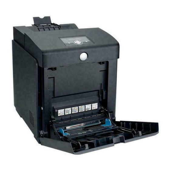
Page 18: Unpacking The Printer
Unpacking the Printer The printer must be carried horizontally with two or more persons. Take extreme care to avoid personal injuries. Check visually the printer for evidence of any damages. Peel all tapes off the printer. Zna00012KB xiii Version 3 2008.05.30... - Page 19 Blank Page Version 1 2007.12.28...
-
Page 20: Table Of Contents
TABLE OF CONTENTS 1. About this manual......................ii 2. Marks giving caution......................ii 3. Related documents......................ii 4. Safety ..........................iii 4.1 Power source ............................iii 4.2 Driving units ............................iv 4.3 High-temperature units ......................... iv 4.4 Laser beams ............................v 4.5 Warning/caution labels...........................vi 4.5.1 Caution label for high-temperature units..................vi 4.5.2 Caution label for toner cartridges.................... - Page 21 Chapter 1 Troubleshooting Chapter 1 Troubleshooting CONTENTS 1. Troubleshooting Overview...................1 - 1 1.1 Flow of Troubleshooting........................1 - 1 1.2 Check Installation Status ......................... 1 - 2 1.3 Cautions on Service Operations ....................... 1 - 3 1.4 Cautions on Using FIP ........................1 - 4 1.5 Items To Be Confirmed Before Going To FIP Troubleshooting ............
- Page 22 Chapter 1 Troubleshooting Chapter 1 Troubleshooting CONTENTS Flows 39 Paper Jam 077-105/077-106....................1 - 83 Flows 40 Paper Jam 077-900/077-901....................1 - 85 Flows 41 Paper Jam 077-903 ......................1 - 89 Flows 42 Paper Jam 077-907 ......................1 - 90 Flows 43 Load Tray N or MPF 024-910/024-911/024-914 ..............
- Page 23 Chapter 1 Troubleshooting Chapter 1 Troubleshooting CONTENTS Flows 94 Noise: During Standby......................1 - 167 Flows 95 Noise: During Printing......................1 - 168 Flows 96 AC............................1 - 172 Flows 97 DC ............................1 - 173 Flows 98 Multiple feed ........................1 - 174 Flows 99 Control Panel Freezes......................
- Page 24 Chapter 1 Troubleshooting Chapter 1 Troubleshooting CONTENTS FIP1.38 Paper Jam 077-104/077-107....................1 - 224 FIP1.39 Paper Jam 077-105/077-106....................1 - 228 FIP1.40 Paper Jam 077-900/077-901....................1 - 231 FIP1.41 Paper Jam 077-903......................1 - 235 FIP1.42 Paper Jam 077-907......................1 - 236 FIP1.43 Load Tray N or MPF 024-910/024-911/024-914 ..............
- Page 25 Chapter 1 Troubleshooting Chapter 1 Troubleshooting CONTENTS FIP-1.P3 Solid black ...........................1 - 292 FIP-1.P4 Vertical blank lines (White stripes in paper transport direction) ..........1 - 294 FIP-1.P5 Horizontal band cross out (White stripes in the horizontal direction) .........1 - 296 FIP-1.P6 Vertical stripes ....................
- Page 26 Chapter 1 Troubleshooting Chapter 1 Troubleshooting CONTENTS Blank Page Version 4.3 2009.08.21...
-
Page 27: Chapter 1 Troubleshooting
Chapter 1 Troubleshooting The troubleshooting procedures described herein assume the use of the Diag Tool. However, the procedures can be performed without the Diag Tool as long as they are carefully followed. 1. Troubleshooting Overview To increase the efficiency of troubleshooting, ensure that preliminary checks should be made to confirm the trouble status before proceeding to the Fault Isolation Procedure (FIP), Operation of Diagnostic (Chapter 2), Wiring Diagrams (Chapter 7), and Principles of Operation (Chapter 6). -
Page 28: Check Installation Status
Chapter 1 Troubleshooting 1.2 Check Installation Status Be sure to check the following items before starting the troubleshooting procedures The power supply voltage is within the specifications (measure the voltage at the wall outlet). The power cord is free from breakage, short-circuit, open wire, or internal miswiring. The printer is properly grounded. -
Page 29: Cautions On Service Operations
Chapter 1 Troubleshooting 1.3 Cautions on Service Operations Be sure to remove the power cord unless otherwise required. While the printer is powered ON, never touch the conductive parts unless otherwise required. Never touch the conductive parts of the power switch and inlet of the LVPS, because they are live even while the printer is powered off. -
Page 30: Cautions On Using Fip
Chapter 1 Troubleshooting 1.4 Cautions on Using FIP When troubleshooting according to the FIP, have on hand a normal MCU, LVPS, HVPS, FUSER ASSY, BELT ASSY, etc., for possible fault isolation. In the initial check according to the FIP, check only items which can be simply checked. In the initial check according to the FIP, check the constitutive parts of the major check parts and related parts, as well as major check parts. - Page 31 Chapter 1 Troubleshooting 14) In the FIP, the paper cassette immediately below the printer main body is called "Tray 1", and the cassette below it is called "Tray 2". 15) Some of the instructions in the FIP are branched off depending on the specifications. Follow the applicable instruction.
-
Page 32: Items To Be Confirmed Before Going To Fip Troubleshooting
Chapter 1 Troubleshooting 1.5 Items To Be Confirmed Before Going To FIP Troubleshooting Basic Printer Problems Some printer problems can be easy to resolve. If a problem occurs with your printer, check each the fol- lowing: If a message is displayed on the LCD of operator panel, see “2.3 Status Code List”. The printer power cable is plugged into the printer and a properly grounded electrical outlet. - Page 33 See "Loading Print Media in Optional Trays" and "Loading the Multipurpose Feeder" for detailed loading instructions. Paper Characteristics The following paper characteristics affect print quality and reliability. Dell recommends that you follow these guidelines when evaluating new paper stock. 1 - 7...
- Page 34 Chapter 1 Troubleshooting Weight The tray automatically feeds paper weights from 60 to 216 g/m2 (16 to 57.6 lb. bond) grain long. The multipurpose feeder automatically feeds paper weights from 60 to 216 g/m2 (16 to 56 lb. bond) grain long.
- Page 35 Chapter 1 Troubleshooting Preprinted papers that require a registration (the precise print location on the page) greater than ±0.09 in., such as optical character recognition (OCR) forms In some cases, you can adjust registration with your software program to successfully print on these forms.
- Page 36 Chapter 1 Troubleshooting Multipurpose Feeder 250-sheet Tray Optional 550-sheet Tray Japanese Post Card Print Media Supported Y: Yes N: No Multipurpose Feeder 250-sheet Tray Optional 550-sheet Tray Plain Paper Light (60-76gsm) Plain Paper Normal (80gms) Plain Paper Thick (82-98gms) Covers Normal (106-163gms) Covers Thick (164-216gms) Transparency Labels...
- Page 37 Chapter 1 Troubleshooting Consumables Near Life Indication Life over Indication When the remaining life of the FUSER When the FUSER reaches its end of life, reaches approximately 20%, the follow- the following messages are displayed. ing messages are displayed. <Panel> <Panel>...
-
Page 38: Fip
Chapter 1 Troubleshooting 2. FIP 2.1 FIP The FIP is the first step for trouble diagnosis. The FIP isolates the presence of various troubles including error codes, and guides the troubleshooting procedure. 2.2 Flow of FIP Ask the operator about trouble status. Is operator's operating method correct? Turn off and turn on the Power. -
Page 39: Status Code List
Chapter 1 Troubleshooting 2.3 Status Code List Error Message FIP to be Error Contents referred Status Window <IOT Fan Motor Failure> Printer error. MCU detects an error upon receiving Flows 1: error signal from the Rear Fan or Rear Fan Turn off the printer, and turn it Duplexer Fan. - Page 40 Chapter 1 Troubleshooting Error Message FIP to be Error Contents referred Status Window Printer error. 004-311 Turn off the printer. Confirm Restart Printer Duplex is correctly installed. <IOT Option Duplexer Failure> Flows 7 Turn on the printer. The error is detected by Option Duplexer Flip FIP1.7 Contact customer support if...
- Page 41 Chapter 1 Troubleshooting Error Message FIP to be Error Contents referred Status Window Printer error. 009-361 Turn off the printer. Confirm Restart Printer toner is correctly installed. <IOT (M) Toner CRUM Error> Flows 16 Turn on the printer. Magenta Toner CRUM communication Flip FIP1.16 Contact customer support if...
- Page 42 Chapter 1 Troubleshooting Error Message FIP to be Error Contents referred Status Window Printer error. 010-354 Turn off the printer, and turn it Restart Printer on again. <IOT environment Sensor Error> Flows 23 Flip Contact customer support if Temperature Sensor Error is detected. FIP1.23 Contact Support this failure is repeated.
- Page 43 Chapter 1 Troubleshooting Error Message FIP to be Error Contents referred Status Window Printer error. 016-302 Turn off the printer, and turn it Restart Printer on again. <ESS Illegal Exception> Flows 25 Flip Contact customer support if CPU illegal exception. FIP1.25 Contact Support this failure is repeated.
- Page 44 Chapter 1 Troubleshooting Error Message FIP to be Error Contents referred Status Window Printer error. 016-318 Turn off the printer, and turn it Restart Printer <ESS DIMM Slot RAM Error> on again. Flows 27 Power-on initialization detected that Flip Contact customer support if FIP1.27 unsupported DIMM was installed.
- Page 45 Chapter 1 Troubleshooting Error Message FIP to be Error Contents referred Status Window Printer error. 016-346 Turn off the printer, and turn it Restart Printer <ESS Network Internal Loopback Error> on again. Flows 25 The error is detected by on board Net- Flip Contact customer support if FIP1.25...
- Page 46 Chapter 1 Troubleshooting Error Message FIP to be Problem Error Contents referred Status Window Paper Jam has occurred Paper Jam at the Tray 1. 071-100 Flip Clear the paper path. <IOT 250 Feeder Misfeed JAM> Open Tray1 Flows 33 Please click the Show The Regi sensor is not turned ON Remove Paper FIP1.33...
- Page 47 Chapter 1 Troubleshooting Error Message FIP to be Problem Error Contents referred Status Window Paper Jam has occurred at the Print Cartridge. Paper Jam <IOT Exit2 JAM> 077-103 Push the Side Button to Fuser Exit Senor detect turn OFF too Flows 37 open the Front Cover Flip...
- Page 48 Chapter 1 Troubleshooting Error Message FIP to be Problem Error Contents referred Status Window Paper Jam has occurred at the Print Cartridge. <IOT Remain Paper JAM> Paper Jam -The remain paper at the Exit Sensor. 077-900 Push the Side Button to -The paper does not reach the Exit Flows 40 open the Front Cover...
- Page 49 Chapter 1 Troubleshooting Error Message FIP to be Problem Error Contents referred Status Window Actual paper size in tray Load Tray 1 and specified paper size 024-910 are different. Flip Load Tray 1 Load the specified paper A4(Paper Size) in Tray 1. Paper Size: A4 Flip Paper Type: Plain...
- Page 50 Chapter 1 Troubleshooting Error Message FIP to be Problem Error Contents referred Status Window An unsupported Cyan Cartridge is installed. Open the Front Cover. CRUM ID Remove the unsup- 009-367 ported Cyan Cartridge and install a supported Flip one. Reseat Please click the Show Cyan Cartridge Me How Button for...
- Page 51 Chapter 1 Troubleshooting Error Message FIP to be Problem Error Contents referred Status Window The sealing tape is still on the Yellow Cartridge. Error Yellow Cart Open the Front Cover. 093-919 Pull the toner seal straight up to remove it. Flip Please click the Show Remove Tape...
- Page 52 Chapter 1 Troubleshooting Error Message FIP to be Problem Error Contents referred Status Window The protection cover is still on the Yellow Car- tridge. Error Yellow Cart Open the Front Cover. 093-950 Remove the protection Flip cover. Remove Sheet Please click the Show from Yellow Cart Me How Button for details.
- Page 53 Chapter 1 Troubleshooting Error Message FIP to be Problem Error Contents referred Status Window The Yellow Cartridge need to be replaced now. Open the Front Cover. Replace Cart. Then remove the used 093-930 Yellow Cartridge and Flip install a new one. Reseat Please click the Show Yellow Cartridge...
- Page 54 Chapter 1 Troubleshooting Error Message FIP to be Problem Error Contents referred Status Window Ready to Print The Yellow Cartridge 093-423 need to be replaced soon. Flip Yellow Cartridge 093-423 Is close to Life Ready to Print The Magenta Cartridge <IOT Print Cartridge Near Empty>...
- Page 55 Chapter 1 Troubleshooting Error Message FIP to be Problem Error Contents referred Status Window The Yellow Cartridge is either missing or not fully inserted into the printer. Insert PrintCart Open the Front Cover 093-970 and make sure that the Flip Yellow Cartridge have Insert been fully installed.
- Page 56 Chapter 1 Troubleshooting Error Message FIP to be Problem Error Contents referred Status Window An unsupported Belt Unit is installed. Open the Front Cover. <IOT Belt Unit CRUM ID Error> CRUM ID Remove the unsup- The Belt Unit CRUM ID error is 009-371 ported Belt Unit and detected.
- Page 57 Chapter 1 Troubleshooting Error Message FIP to be Problem Error Contents referred Status Window The Fuser needs to be replaced now. 010-351 Remove the used Fuser Restart Printer <IOT Fuser Life Over> and install a new one. Flows 22 The Fuser Counter has reached the Flip Please click the Show FIP1.22...
- Page 58 Chapter 1 Troubleshooting Error Message FIP to be Problem Error Contents referred Status Window Firmware download ID error has occurred. Invalid ID 016-383 Press the Set Button. <Download Error> Flows 66 Contact customer sup- An error occurred because an invalid Flip FIP1.66 port if this failure is...
- Page 59 Chapter 1 Troubleshooting Error Message FIP to be Problem Error Contents referred Status Window Firmware download delete error has Erase Flash Err. occurred. 016-392 <Download Error> Flows 25 Contact customer sup- Flip An error occurred erasing the Flash. FIP1.25 port if this failure is Contact Support repeated.
- Page 60 Chapter 1 Troubleshooting Error Message FIP to be Problem Error Contents referred Status Window Disk space is insuffi- cient and cannot con- tinue processing the current print job. Collate Full 016-981 Press Set Button to <Memory Over flow> Flows 69 clear the message, can- Exceeds the memory capacity.
- Page 61 193-700 <Custom Toner Mode> Flows 75 No Message. Flip The printer is in custom toner mode. FIP1.71 Other non-DELL Toner Installed An internal temperature of the printer became a Over Heat high temperature. 042-700 <IOT Over Heat Stop> Flows 76 Please wait for a while The temp.
-
Page 62: Error Code Fip
Chapter 1 Troubleshooting 3. Error Code FIP 3.1 Troubleshooting for the call center Flows 1 001-360-01 Restart Printer Checking the detail error code. A detailed error code is displayed by pushing key, key simultaneously. Is "Code: 01" displayed on the LCD? Checking the FAN MAIN Go to Flows 2 Does the FAN MAIN... -
Page 63: Flows 2 001-360-02 Restart Printer
Chapter 1 Troubleshooting Flows 2 001-360-02 Restart Printer Checking the detail error code. A detailed error code is displayed by pushing key, key simultaneously. Is "Code: 02" displayed on the LCD? Checking the FAN DUP Go to Flows 1 Does the FAN DUP function normally? Checked by [Digital Output] - [DO- 5d(Control Panel)/... -
Page 64: Flows 3 003-340-01/003-340-02/003-340-03/003-340-04/003-340-05/003-340-07/003
Chapter 1 Troubleshooting Flows 3 003-340-01/003-340-02/003-340-03/003-340-04/003-340-05/003-340-07/003- 340-08/003-340-0A/003-340-0B/003-340-14 Restart Printer Checking the detail error code. A detailed error code is displayed by pushing key, key simultaneously. Is "Code: 09" displayed on the LCD? Checking the error occurring Go to Flows 4 Does the error still occur after several ON/OFF operations... -
Page 65: Flows 4 003-340-09 Restart Printer
Chapter 1 Troubleshooting Flows 4 003-340-09 Restart Printer Checking the detail error code. A detailed error code is displayed by pushing key, key simultaneously. Is "Code: 09" displayed on the LCD? Checking the error Go to Flows 3 Does the error still occur when the power is turned off and on? -
Page 66: Flows 5 003-356 Restart Printer
Chapter 1 Troubleshooting Flows 5 003-356 Restart Printer Checking the error Does the error still occur when the power is turned off and on? Checking the failure parts Press the " ", the " " and the " " keys on the Control Panel when displaying the error code. The failure parts code (address code on a memory) is displayed on the LCD. -
Page 67: Flows 6 004-310 Restart Printer
Chapter 1 Troubleshooting Flows 6 004-310 Restart Printer Checking the Optional Feeder installing Reseat the Optional Feeder. (Removal 44/Replacement Does the error still occur when turning on the power? Checking after replacing the Optional Feeder Replace the Optional Feeder. (Removal 44/Replacement Does the error still occur when turning on the power? -
Page 68: Flows 7 004-311 Restart Printer
Chapter 1 Troubleshooting Flows 7 004-311 Restart Printer Checking Optional Duplexer installation to the printer. Reseat the FEEDER ASSY DUP. (Removal 5/Replacement 39) Does the error still occur when the power is turned ON? Replace the FEEDER ASSY DUP. (Removal 5/Replacement 39) Does the error still occur when the... -
Page 69: Flows 8 006-370 Restart Printer
Chapter 1 Troubleshooting Flows 8 006-370 Restart Printer Checking the error Does the error still occur when the power is turned off and on? Replace the ROS ASSY. (Removal 36/Replacement Does the error still occur when the power is turned ON? Replace the Printer.(There is doubt about wire separation.) -
Page 70: Flows 9 007-340-00 Restart Printer
Chapter 1 Troubleshooting Flows 9 007-340-00 Restart Printer Checking the detail error code. A detailed error code is displayed by pushing key, key simultaneously. Is "Code: 00" displayed on the LCD? Checking the Transfer Assy, Fuser "01" : Flows 10, and Black Print Cartridge for "03"... -
Page 71: Flows 10 007-340-01 Restart Printer
Chapter 1 Troubleshooting Flows 10 007-340-01 Restart Printer Checking the detail error code. A detailed error code is displayed by pushing key, key simultaneously. Is "Code: 01" displayed on the LCD? Checking the print cartridges "00" : Flows 9, installation "03"... -
Page 72: Flows 12 007-340-03 Restart Printer
Chapter 1 Troubleshooting Flows 12 007-340-03 Restart Printer Checking the detail error code. A detailed error code is displayed by pushing key, key simultaneously. Is "Code: 03" displayed on the LCD? Checking the tray1 paper "00" : Flows 9, cassette installation "02"... -
Page 73: Flows 13 007-340-04 Restart Printer
Chapter 1 Troubleshooting Flows 13 007-340-04 Restart Printer Checking the detail error code. A detailed error code is displayed by pushing key, key simultaneously. Is "Code: 04" displayed on the LCD? "00" : Flows 9, Checking the paper "02" : Flows 11, cassette installation "03"... -
Page 74: Flows 14 007-371 Restart Printer
Chapter 1 Troubleshooting Flows 14 007-371 Restart Printer Checking after replacing the DRIVE ASSY K. Replace the DRIVE ASSY K. (Refer to Removal 28/Replacement 16.) Does the error still occur when turning on the power? Replace the Printer. 1 - 48 Version 3 2008.05.30... -
Page 75: Flows 15 009-360 Restart Printer
Checking the Print Cartridge Is the print cartridge installed to the printer the DELL toner? Checking the Yellow Print Set to the [Non DELL Cartridge for installation Toner] Mode or replace Reseat the Yellow Print to the DELL toner. Cartridge. -
Page 76: Flows 16 009-361 Restart Printer
Checking the Print Cartridge Is the print cartridge installed to the printer the DELL toner? Checking the Magenta Print Set to the [Non DELL Cartridge for installation Toner] Mode or replace Reseat the Magenta Print to the DELL toner. Cartridge. -
Page 77: Flows 17 009-362 Restart Printer
Checking the Print Cartridge Is the print cartridge installed to the printer the DELL toner? Checking the Cyan Print Set to the [Non DELL Cartridge for installation Toner] Mode or replace Reseat the Cyan Print to the DELL toner. Cartridge. -
Page 78: Flows 18 009-363 Restart Printer
Checking the Print Cartridge Is the print cartridge installed to the printer the DELL toner? Checking the Black Print Set to the [Non DELL Cartridge for installation Toner] Mode or replace Reseat the Black Print to the DELL toner. Cartridge. -
Page 79: Flows 19 009-654-01 Restart Printer
Chapter 1 Troubleshooting Flows 19 009-654-01 Restart Printer Checking the detail error code. A detailed error code is displayed by pushing key, key simultaneously. Is "Code: 01" displayed on the LCD? Checking the Go to Flows 20 TRANSFER ASSY for installation. - Page 80 Chapter 1 Troubleshooting Checking the ADC Sensor solenoid of TRANSFER ASSY for operation. Does the ADC Sensor operate normally? Checked by [Digital Output] - [DO-37(Control Panel)/CTD SOLENOID ON(PC)] in diagnosis. Replace the TRANSFER Replace the corresponding ASSY (Refer to Removal CARTRIDGE ASSY.
-
Page 81: Flows 20 009-654-02 Restart Printer
Chapter 1 Troubleshooting Flows 20 009-654-02 Restart Printer Checking the detail error code. A detailed error code is displayed by pushing key, key simultaneously. Is "Code: 02" displayed on the LCD? Checking the TRANSFER Go to Flows 19 ASSY for installation. Reseat the TRANSFER ASSY. - Page 82 Chapter 1 Troubleshooting Checking the ADC Sensor solenoid of TRANSFER ASSY for operation. Does the ADC Sensor operate normally? Checked by [Digital Output] - [DO-37(Control Panel)/CTD SOLENOID ON(PC)] in diagnosis. Replace the TRANSFER Replace the ROS ASSY. ASSY.(Refer to Removal (Removal 36/ Replacement 4/Replacement 40) and the PWBA MCU.(Removal...
-
Page 83: Flows 21 010-317 Restart Printer
Chapter 1 Troubleshooting Flows 21 010-317 Restart Printer Checking FUSER ASSY installation Is FUSER ASSY installed correctly? Reseat the FUSER ASSY. (Removal 8/ Replacement 36) Does the error still occur after several ON/OFF operations of power? Checking after replacing END *1 the FUSER ASSY. -
Page 84: Flows 22 010-351 Restart Printer
Chapter 1 Troubleshooting Flows 22 010-351 Restart Printer This error code is displayed when the Fuser ASSY has reached its end of life and needs replacing. Immediately replace the Fuser ASSY with a new one. If this error code is displayed although the Fuser ASSY has been replaced only recently, follow the following flow. -
Page 85: Flows 23 010-354 Restart Printer
Chapter 1 Troubleshooting Flows 23 010-354 Restart Printer Checking the temperature and humidity inside a machine. Checked by [Get Environment Sensor Info] of the [Diagnosis] tab in Tool Box. Exact temperature/ humidity are displayed? Replace the PWBA the SENSOR HUM. (Removal 29/ Replacement 15). -
Page 86: Flows 24 010-377 Restart Printer
Chapter 1 Troubleshooting Flows 24 010-377 Restart Printer Checking the FUSER ASSY installation Reseat the FUSER ASSY. Does the error still occur when turning on the power? Checking after replacing the FUSER ASSY Replace the FUSER ASSY. Does the error still occur when turning on the power? Replace the LVPS. -
Page 87: Flows 25 016-300/016-301/016-302/016-310/016-313/016-315/016-317/016-323/016
Checked by [Printer Information] Mode". (Refer to Refernce_1.) of the [Printer Settings Report] tab in Tool Box. For the latest version information, refer to the Dell Support Web Site. Does the error still occur when the power is turned off... -
Page 88: Flows 25-1 016-340 Restart Printer
Replace the PWBA Replacement 18) ESS. (Removal 26/ Replacement 18) Download the latest version of the firmware from the Dell support website, and update the firmware with "F/W Download DL Mode". (Refer to Refernce_2.) Does the error persist when the... - Page 89 Chapter 1 Troubleshooting Reference_1:Changing the IP address 1) Remove the network cable, and power off the printer and then on 2) Change the IP address on the Control Panel. 3) Plug the network cable back into the printer, and then turn the power on. 4) On the Control Panel, open [Admin] >...
-
Page 90: Flows 26 016-312/016-361 Restart Printer
Chapter 1 Troubleshooting Flows 26 016-312/016-361 Restart Printer Checking the HDD ASSY (OPTION) for installation Reseat the HDD ASSY (OPTION). Does the error still occur when the power is turned Checking after replacing the HDD ASSY (OPTION) Replace the HDD ASSY (OPTION). -
Page 91: Flows 27 016-316/016-318 Restart Printer
Is the memory card recommended by Dell used? Checking the Memory Use the memory card Card installation. recommended by Dell. Reseat the Memory Card. Does the error still occur when turning on the power? Checking after replacing the Memory Card. -
Page 92: Flows 28 016-338 Restart Printer
Chapter 1 Troubleshooting Flows 28 016-338 Restart Printer Checking the connected device to the USB port on the PWBA ESS. Is the Wireless Printer Adapter connected to the USB port on the PWBA ESS? Connect the Wireless Checking the Wireless Printer Adapter to the Printer Adapter installation USB port on the PWBA... -
Page 93: Flows 29 016-350 Restart Printer
Chapter 1 Troubleshooting Flows 29 016-350 Restart Printer Checking the PC and the cable Swap the another PC and cable. Does the error still occur when printing? Check the PC setting Replace the PWBA and disconnection of ESS. (Refer to the cable Removal 26/ Replacement 18) -
Page 94: Flows 30 016-365 Restart Printer
Is the Checking after reseating NETWORK the Network Adapter PROTOCOL Reseat the NETWORK ADAPTER for PROTOCOL ADAPTER. 3130cn installed? Install the NETWORK PROTOCOL ADAPTER for 3130cn. Does the error still occur when the power is turned Checking after replacing the Network... -
Page 95: Flows 31 016-370 Restart Printer
Download the latest version of the firmware from the Dell support website, and update the firmware with "F/W Download DL Mode". (Refer to Refernce_1.) Does the error still occur... - Page 96 Chapter 1 Troubleshooting Reference_1: 1. Make sure that the printer is connected to the computer via USB port or Parallel port (remove the network cable). Then, try downloading as follows: 1) Power on the printer while pressing the <X Cancel> and < > buttons. 2) Press <...
-
Page 97: Flows 32 093-964 Restart Printer
Example) FUSER for 100V XX-0M507D-XXXXX-XXX-XXXX PPID No. Checking the FUSER ASSY type Note: The PPID numbers of the FUSER ASSY for 3130cn are as follows: - PPID No.(For 100V): 0M507D - PPID No.(For 110V): 0M508D - PPID No.(For 220V): 0M509D... -
Page 98: Chapter 1 Troubleshooting Contents
Chapter 1 Troubleshooting Flows 33 Paper Jam 071-100 Checking the paper condition Is the paper in the Tray wrinkled or damaged? Replace the paper with a Checking the paper size new and dry one. setup Does the paper size in use match the size set? Checking the paper size setting... - Page 99 Chapter 1 Troubleshooting Checking the Regi Sensor for operation Does the number on the screen increase by one, every time the actuator of the SENSOR PHOTO (REGI SENSOR) is operated? Checked by [Digital Input] - [DI- 3(Control Panel)/REGI SNR (PC)] in diagnosis. Replace the FEEDER Checking the DRIVE ASSY ASSY.
-
Page 100: Flows 34 Paper Jam
Chapter 1 Troubleshooting Flows 34 Paper Jam 072-100 Checking the paper condition Is the paper in the Tray wrinkled or damaged? Replace the paper with a Checking the paper size new and dry one. setup Does the paper size in use match the size set? Checking the paper size setting... - Page 101 Chapter 1 Troubleshooting Checking the Regi Sensor for operation Does the number on the screen increase by one, every time the actuator of the SENSOR PHOTO (REGI SENSOR) is operated? Checked by [Digital Input] - [DI- 3(Control Panel)/REGI SNR (PC)] in diagnosis. Replace the FEEDER Checking the DRIVE ASSY ASSY.
- Page 102 Chapter 1 Troubleshooting Checking the CLUTCH ASSY PH TURN for operation Does the CLUTCH ASSY PH TURN operate properly? Checked by [Digital Output] - [DO-33(Control Panel)/ CASSETTE2 TURN CLUTCH ON(PC)] in diagnosis. Checking the ROLL ASSY Replace the CLUTCH TURN and ROLL ASSY ASSY PH TURN.
-
Page 103: Flows 35 Paper Jam
Chapter 1 Troubleshooting Flows 35 Paper Jam 075-100 Checking the Regi Sensor for operation Does the number on the screen increase by one, every time the actuator of the SENSOR PHOTO (REGI SENSOR) is operated? Checked by [Digital Input] - [DI- 3(Control Panel)/REGI SNR (PC)] in diagnosis. - Page 104 Chapter 1 Troubleshooting Checking the DRIVE ASSY PH for operation Does the DRIVE ASSY PH operate properly? Checked by [Digital Output] - [DO-a(Control Panel)/PH MOTOR(FULL)(PC)] in diagnosis. Checking the ROLL ASSY Replace the DRIVE ASSY SEPARATER, ROLL ASSY FEED MSI and ROLL (Refer to Removal 17/ ASSY TURN for shape and Replacement 27.)
- Page 105 Chapter 1 Troubleshooting Flows 36 Paper Jam 077-100/077-101 Checking the REGI Rolls installation Open the Front Cover and check the Regi Rolls installation. Is the ROLL REGI METAL pressed against the ROLL ASSY REGI by the spring pressure? Checking the REGI Replace the printer.
- Page 106 Chapter 1 Troubleshooting Flows 37 Paper Jam 077-102/077-103 Checking the EXIT SENSOR for operation Does the number on the screen increase by one, when the actuator of the Exit Sensor in the FUSER ASSY is operated? Checked by [Digital Input] - [DI- 2(Control Panel)/EXIT SNR(PC)] in diagnosis.
- Page 107 Chapter 1 Troubleshooting Flows 38 Paper Jam 077-104/077-107 Checking the Rolls installation Are the Rolls on the FEEDER ASSY DUP installed correctly? Replace the FEEDER Checking the damages on ASSY DUP. the surface of the Rolls (Refer to Removal 5/ Replacement 39.) Are there any damages on the...
- Page 108 Chapter 1 Troubleshooting Checking the CLUTCH ASSY PH TURN for operation Does the CLUTCH ASSY PH TURN operate properly? Checked by [Digital Output] - [DO-2b (Control Panel)/MSI TURN CLUTCH ON(PC)] in diagnosis. Checking the PH Motor for Replace the CLUTCH operation ASSY PH TURN.
- Page 109 Chapter 1 Troubleshooting Flows 39 Paper Jam 077-105/077-106 Checking the Rolls installation Are the Rolls on the FEEDER ASSY DUP installed correctly? Replace the FEEDER Checking the damages on ASSY DUP. the surface of the Rolls (Refer to Removal 5/ Replacement 39.) Are there any damages on the...
- Page 110 Chapter 1 Troubleshooting Checking the MOTOR ASSY DUP for operation Does the MOTOR ASSY DUP operate properly? Checked by [Digital Output] - [DO-13(Control Panel)/ DUPLEX MOTOR ON (PC)] in diagnosis. Replace the PWBA MCU. Replace the FEEDER ASSY DUP. (Refer to Removal 30/ Replacement 14.) (Refer to Removal 5/ Replacement 39.)
-
Page 111: Flows 40 Paper Jam 077-900/077-901
Chapter 1 Troubleshooting Flows 40 Paper Jam 077-900/077-901 Checking the paper condition Is the paper in the Tray wrinkled or damaged? Replace the paper with a Checking the Front Cover new and dry one. latching Open and close the Front Cover, check the latching. - Page 112 Chapter 1 Troubleshooting Checking the Regi Sensor for operation Does the number on the screen increase by one, every time the actuator of the SENSOR PHOTO (REGI SENSOR) is operated? Checked by [Digital Input] - [DI- 3(Control Panel)/REGI SNR(PC)] in diagnosis.
- Page 113 Chapter 1 Troubleshooting Checking the PH motor for operation Does the PH Motor operate properly? Checked by [Digital Output] - [DO-a(Control Panel)/PH MOTOR ON(PC)] in diagnosis. Checking the CLUTCH Replace the DRIVE ASSY ASSY PH REGI for MAIN. (Refer to Removal operation 38/ Replacement 6.) Does the...
- Page 114 Chapter 1 Troubleshooting Checking the ROLL REGI RUBBER and ROLL REGI METAL for shape and operation Are ROLL REGI RUBBER and ROLL REGI METAL installed correctly? Also are they not contaminated and /or damaged, and rotate smoothly? Check these ROLLs by turning them with Replace the defective Checking the TRANSFER...
-
Page 115: Flows 41 Paper Jam 077-903
Chapter 1 Troubleshooting Flows 41 Paper Jam 077-903 Checking the jam Remove the jammed paper. Does the error still occur when printing? Checking the Regi Sensor for operation Does the number on the screen increase by one, every time the actuator of the SENSOR PHOTO (REGI SENSOR) is operated? Checked by [Digital Input] - [DI-... -
Page 116: Flows 42 Paper Jam 077-907
Chapter 1 Troubleshooting Flows 42 Paper Jam 077-907 Checking the COVER ASSY FRONT for latching Open and close the COVER ASSY FRONT, then check the latching. Does the error still occur when printing? Checking after reseating the FUSER ASSY Reseat the FUSER ASSY. Does error still occur when printing? Checking after reseating... - Page 117 Chapter 1 Troubleshooting Checking the CHUTE ASSY EXIT OUT for shape and installation Are the shape and the installation of the CHUTE ASSY EXIT OUT normal? Reseat the CHUTE ASSY Checking the SENSOR EXIT OUT. PHOTO (DUP JAM If broken, replace the SENSOR) for operation CHUTE ASSY EXIT OUT.
- Page 118 Chapter 1 Troubleshooting Checking the MOTOR ASSY DUP for operation Does the MOTOR ASSY DUP operate properly? Checked by [Digital Output] - [DO-13(Control Panel)/ DUPLEX MOTOR ON(PC)] in diagnosis. Checking the CLUTCH Replace the FEEDER ASSY ASSY PH TURN for operation (Refer to Removal 5/ Replacement 39.)
-
Page 119: Flows 43 Load Tray N Or Mpf 024-910/024-911/024-914
Chapter 1 Troubleshooting Flows 43 Load Tray N or MPF 024-910/024-911/024-914 Checking the paper size. Does the paper size in use meet the specification? Use the paper that meets Checking the paper size setup. the specification. Does the paper size in use match the size set Feeder through the control... - Page 120 Chapter 1 Troubleshooting Checking the paper cassette guide Reseat the end guide of paper cassette. Does the error still occur when printing? Checking after replacing the CASSETTE ASSY 250 or 550 Replace the CASSETTE ASSY 250 or 550. Does the error still occur when printing? Replace the PWBA MCU.
-
Page 121: Flows 44 Load Tray N Or Mpf 024-965/024-966/024-969
Chapter 1 Troubleshooting Flows 44 Load Tray N or MPF 024-965/024-966/024-969 Checking the paper In specified the tray or the cassette, is there the paper? Checking the paper size Load the paper Check the paper size below. -Paper in the cassette or the tray -Paper size setting by the control panel -Paper size of the printing job Are these paper size... - Page 122 Chapter 1 Troubleshooting Checking the ACTUATOR NO PAPER MSI Does the ACTUATOR NO PAPER MSI operate smoothly? Checking the SENSOR Replace the ACTUATOR PHOTO (No Paper ASSY MSI. Sensor) Does the number on the screen increase by one, every time the actuator of the SENSOR PHOTO (MSI NO PAPER) is operated? Checked by [Digital Input] - [DI-...
- Page 123 Chapter 1 Troubleshooting Does the ACTUATOR NO PAPER operate smoothly? Checking the SENSOR Replace the PHOTO (No Paper ACTUATOR NO Sensor) PAPER A4. Checking the SENSOR PHOTO (CST NO PAPER) for operation Does the number on the screen increase by one, every time the actuator of the SENSOR PHOTO (CST NO PAPER) is operated? Checked by [Digital Input] - [DI-11(Control...
-
Page 124: Flows 45 Crum Id 009-367/009-368/009-369/009-370
Are the Print Cartridges installed to the printer the DELL Toner? Set the non-DELL toner mode through Checking the DELL toner type the control panel. Is the print cartridge installed the 3130 Checking the Print Replace the print Cartridge installation cartridge for 3130cn. -
Page 125: Flows 46 Error Y Cart 093-919
Chapter 1 Troubleshooting Flows 46 Error Y Cart 093-919 Every unused Print Cartridge originally installed in the printer is covered with a Toner Tape that protects the drum from intense light. This error is displayed when the printer is operated without removing the Toner Tape. Open the Front Cover to check if the Toner Tape is affixed on the Print Cartridge (Y). -
Page 126: Flows 47 Error M Cart 093-920
Chapter 1 Troubleshooting Flows 47 Error M Cart 093-920 Every unused Print Cartridge originally installed in the printer is covered with a Toner Tape that protects the drum from intense light. This error is displayed when the printer is operated without removing the Toner Tape. Open the Front Cover to check if the Toner Tape is affixed on the Print Cartridge (M). -
Page 127: Flows 48 Error C Cart 093-921
Chapter 1 Troubleshooting Flows 48 Error C Cart 093-921 Every unused Print Cartridge originally installed in the printer is covered with a Toner Tape that protects the drum from intense light. This error is displayed when the printer is operated without removing the Toner Tape. Open the Front Cover to check if the Toner Tape is affixed on the Print Cartridge (C). -
Page 128: Flows 49 Error K Cart 093-922
Chapter 1 Troubleshooting Flows 49 Error K Cart 093-922 Every unused Print Cartridge originally installed in the printer is covered with a Toner Tape that protects the drum from intense light. This error is displayed when the printer is operated without removing the Toner Tape. Open the Front Cover to check if the Toner Tape is affixed on the Print Cartridge (K). -
Page 129: Black Toner
Chapter 1 Troubleshooting Flows 50 093-950 Yellow Toner / 093-951 Magenta Toner / 093-952 Cyan Toner / 093- 953 Black Toner Every reorder Print Cartridge is covered with an orange Protect Cover (At the time of printer purchase, it is Protect Paper.)that protects the drum from intense light. This error is displayed when the printer is operated without removing the Protect Cover(or Protect Paper). -
Page 130: Flows 51 Replace Cart 093-930/093-931/093-932/093-933
Chapter 1 Troubleshooting Flows 51 Replace Cart 093-930/093-931/093-932/093-933 This error code is displayed when the Print Cartridge (Y, M, C, or K) has reached its end of life and needs replacing. Immediately replace the Print Cartridge (Y, M, C, or K) with a new one. If this error code is displayed although the Print Cartridge (Y, M, C, or K) has been replaced only recently, follow the following flow. -
Page 131: Flows 52 Ready To Print 093-423/093-424/093-425/093-426
Chapter 1 Troubleshooting Flows 52 Ready to Print 093-423/093-424/093-425/093-426 This error code is not a fault warning and only denotes that the Print Cartridge (Y, M, C, or K) is approaching but has not reached its end of life. Immediately prepare a new Print Cartridge (Y, M, C, or K). If this error code is displayed although the Print Cartridge (Y, M, C, or K) has been replaced only recently, follow the following flow. -
Page 132: Flows 53 Insert Print Cart 093-970
Chapter 1 Troubleshooting Flows 53 Insert Print Cart 093-970 Checking the print cartridge installation Reseat the print cartridge on correct Y position Does the error still occur when turning on the power? Checking after replacing the CARTRIDGE ASSY (Y) Replace the CARTRIDGE ASSY (Y). -
Page 133: Flows 54 Insert Print Cart 093-971
Chapter 1 Troubleshooting Flows 54 Insert Print Cart 093-971 Checking the print cartridge installation Reseat the print cartridge on correct M position Does the error still occur when turning on the power? Checking after replacing the CARTRIDGE ASSY (M) Replace the CARTRIDGE ASSY (M). -
Page 134: Flows 55 Insert Print Cart 093-972
Chapter 1 Troubleshooting Flows 55 Insert Print Cart 093-972 Checking the print cartridge installation Reseat the print cartridge on correct C position Does the error still occur when turning on the power? Checking after replacing the CARTRIDGE ASSY (C) Replace the CARTRIDGE ASSY (C). -
Page 135: Flows 56 Insert Print Cart 093-973
Chapter 1 Troubleshooting Flows 56 Insert Print Cart 093-973 Checking the print cartridge installation Reseat the print cartridge on correct K position Does the error still occur when turning on the power? Checking after replacing the CARTRIDGE ASSY (K) Replace the CARTRIDGE ASSY (K). -
Page 136: Flows 57 Crum Id
ON? Checking the TRANSFER ASSY type Note: The PPID No. of the TRANSFER ASSY for 3130cn is as follows: - PPID No.: 0R298D Is the TRANSFER ASSY for 3130cn installed? Install the Replace the Printer. -
Page 137: Flows 58 Ready To Print 094-422
Chapter 1 Troubleshooting Flows 58 Ready to Print 094-422 This error code is not a fault warning and only denotes that the Transfer ASSY (Belt Unit) is approaching but has not reached its end of life. Immediately prepare a new Transfer ASSY (Belt Unit). If this error code is displayed although the Transfer ASSY (Belt Unit) has been replaced only recently, follow the following flow. -
Page 138: Flows 59 Insert Belt Unit 094-910
Chapter 1 Troubleshooting Flows 59 Insert Belt Unit 094-910 Checking the TRANSFER ASSY for installation Is the TRANSFER ASSY installed correctly? Checking after replacing Reseat the the TRANSFER ASSY TRANSFER ASSY Replace the TRANSFER ASSY. (Refer to Removal 4/Replacement 40) Does the error still occur when the power is turned... -
Page 139: Flows 60 Belt Unit 094-911
Chapter 1 Troubleshooting Flows 60 Belt Unit 094-911 This error code denotes that the Transfer ASSY (Belt Unit) has reached its end of life and needs replacing. Immediately replace the Transfer ASSY (Belt Unit) with a new one. If this error code is displayed although the Transfer ASSY (Belt Unit) has been replaced only recently, follow the following flow. -
Page 140: Flows 61 010-359 Restart Printer
Example) FUSER for 100V XX-0M507D-XXXXX-XXX-XXXX PPID No. Checking the FUSER ASSY type Note: The PPID numbers of FUSER ASSY for 3130cn are as follows: - PPID No.(For 100V): 0M507D - PPID No.(For 110V): 0M508D - PPID No.(For 220V): 0M509D Is the FUSER... -
Page 141: Flows 62 Ready To Print 010-421
Chapter 1 Troubleshooting Flows 62 Ready to Print 010-421 This error code is not a fault warning and only denotes that the Fuser ASSY is approaching but has not reached its end of life. Immediately prepare a new Fuser ASSY. If this error code is displayed although the Fuser ASSY has been replaced only recently, follow the following flow. -
Page 142: Flows 63 Tray Detached 024-946/007-912
Chapter 1 Troubleshooting Flows 63 Tray Detached 024-946/007-912 Checking the CASSETTE ASSY installation Reseat the CASSETTE ASSY. Does the error still occur when turning on the power? Checking the SWITCH ASSY SIZE Does the SWITCH ASSY SIZE function normally? Checked by [Digital Input] - [DI-18(Control Panel)/ CASSETTE1 SIZE (PC)] in... -
Page 143: Flows 64 Load Tray 024-947
Chapter 1 Troubleshooting Flows 64 Load Tray 024-947 Checking the 550 OPTION CASSETTE ASSY installation Reseat the 550 OPTION CASSETTE ASSY. Does the error still occur when turning on the power? Checking the SWITCH ASSY SIZE OPT Does the SWITCH ASSY SIZE OPT function normally? Checked by [Digital Input] - [DI-20(Control Panel)/... -
Page 144: Flows 65 Close Front Cover
Chapter 1 Troubleshooting Flows 65 Close Front Cover 077-300 Checking the Front Cover Is the Front Cover closed? Checking the LATCH Close the Front Cover. FRONT(PL1.2.4) for shape Is there any damage on the two projections on the LATCH FRONT (Refer to PL1.2.4) inside the Front Cover? Checking the interlock... - Page 145 Checked by [Printer Information] of the [Printer Settings Report] tab in Tool Box. For the latest version information, refer to the Dell Support Web Site. Is the firmware the latest version? Check the cable between the Download the latest version...
-
Page 146: Flows 67 Out Of Memory 016-700
Chapter 1 Troubleshooting Flows 67 Out of Memory 016-700 Checking for memory expansion. Is additional memory installed? Check Print Mode settings. Is Print Mode set to standard? Check RAM DISK settings Set Print Mode to via System Setting in standard. Printer Maintenance tab of Tool Box. -
Page 147: Flows 68 Disc Full 016-980
Chapter 1 Troubleshooting Flows 68 Disc Full 016-980 Checking for HDD expansion Is additional HDD installed? Clear space in HDD. Check Print Mode settings. Is Print Mode set to standard? Set Print Mode to Clear the data on the RAM standard. -
Page 148: Flows 69 Collate Full 016-981
Chapter 1 Troubleshooting Flows 69 Collate Full 016-981 Retrying printing Does the error persist even after retries? Checking the printer memory size Does the error occur when printing with the Memory Card (Option) installed? RAM Disk size settings Does the error occur when printing after reducing the size setting of the RAM Disk? - Page 149 Dell Support web site. Are the printer driver and firmware the latest versions? This job cannot be Download the latest printer executed. driver and firmware from the Dell Support web site. 1 - 123 Version 3 2008.05.30...
-
Page 150: Flows 70 016-720 Pdl Error
Chapter 1 Troubleshooting Flows 70 016-720 PDL Error Checking the printing job Print the small size file (like a Windows test print). Does the error still occur when printing? Checking after reseating the PWBA ESS Reseat the PWBA ESS. Does the error still occur when printing? Replace the PWBA ESS. -
Page 151: Flows 71 Invalid User 016-757
Chapter 1 Troubleshooting Flows 71 Invalid User 016-757 Checking for error Does the error persist even after powering off and on? Your account may be nonexisting or incorrectly configured. Contact your administrator. 1 - 125 Version 2 2008.03.27... -
Page 152: Flows 72 Disabled Func 016-758
Chapter 1 Troubleshooting Flows 72 Disabled Func 016-758 Checking for error Does the error persist even after powering off and on? Color printing is not allowed via the Color Track settings. Change your settings to B&W or ask your administrator to authorize color printing. -
Page 153: Flows 73 Reached Limits 016-759
Chapter 1 Troubleshooting Flows 73 Reached Limits 016-759 Checking for error Does the error persist even after powering off and on? An attempt was made to print more copies than the print count limit. Contact your administrator. 1 - 127 Version 2 2008.03.27... -
Page 154: Flows 74 Invalid Job 016-799
Chapter 1 Troubleshooting Flows 74 Invalid Job 016-799 Checking for error Does the error persist even after powering off and on? The current print settings (size, tray selection, etc.) is invalid for printing. Change the settings and retry. 1 - 128 Version 2 2008.03.27... -
Page 155: Flows 75 Ready To Print 193-700
Menu] is turned to [ON] for using non-Dell toner cartridge. Printing is available while this message is displayed. Use of a non-Dell print cartridge may result in some of the printer's functions to be unavailable, a reduction in print quality, or deterioration of printer's reliability. Use of a new Dell brand print cartridge is recommended for your printer. -
Page 156: Flows 76 Over Heat 042-700 / Ready To Print 142-700
Chapter 1 Troubleshooting Flows 76 Over Heat 042-700 / Ready to Print 142-700 - The error code "042-700" is displayed when the internal temperature of the printer has risen to somewhere near the predetermined value due to a large volume 2- sided printing. -
Page 157: Flows 77 Electrical Noise
Chapter 1 Troubleshooting Flows 77 Electrical Noise Checking the external noise Are there any other electrical appliances within 3 meters of the printer, such as generators, radio and appliances with motors? Ether turn off the other electrical appliances, or relocate the printer at least 6 meters from other appliances. -
Page 158: Flows 78 Faint Print (Low Contrast)
Checking the print which the problem cartridge installed. generated. Is the installed print cartridge the DELL cartridge? Checking the printer Replace to the DELL setting cartridge and print ten sheets [Test Print]-[Toner Pallet Check] in diagnosis. Is the [Draft Mode] of the... - Page 159 Chapter 1 Troubleshooting Checking the paper Is the installed paper with a new and dry one? Replace the paper Checking the print with a new and dry cartridge one. Is there the faint color? Checked by [Test Print]- [Toner Pallet Check] in diagnosis.
-
Page 160: Flows 79 Blank Print (No Print)
Chapter 1 Troubleshooting Flows 79 Blank print (No print) Checking the blank print. Print the Contamination Check page. Is the image printed correctly? Checked by [Test Print] - [contamination Check] in diagnosis. Slide the Print Cartridge in and out, which has blank print color samples, three times. -
Page 161: Flows 80 Solid Black
Chapter 1 Troubleshooting Flows 80 Solid black Checking the solid black. Print the Contamination Check page. Is the image printed correctly? Checked by [Test Print] - [contamination Check] in diagnosis. Checking the Test Pattern. Check the print data which Print the Test Pattern the problem generated. -
Page 162: Flows 81 Vertical Blank Lines (White Stripes In Paper Transport Direction)
Chapter 1 Troubleshooting Flows 81 Vertical blank lines (White stripes in paper transport direction) Random Periodic Mnt01102KA Mnt01103KA Checking the Vertical blank lines. Print the Contamination Check page. Is the image printed correctly? Checked by [Test Print] - [contamination Check] in diagnosis. - Page 163 DELL cartridge? 31.4/56.9 TRANSFER BELT ASSY 82.7/94.2/18.8/43.1/31.4 FUSER ASSY Checking the paper Replace to the DELL cartridge and print ten sheets [Test Print]-[Toner Pallet Check] in diagnosis. Is the installed paper with a new and dry one?
-
Page 164: Flows 82 Horizontal Band Cross Out (White Stripes In The Horizontal Direction)
Chapter 1 Troubleshooting Flows 82 Horizontal band cross out (White stripes in the horizontal direction) Random Periodic Mnt01104KA Mnt01105KA Checking the Horizontal band cross out. Print the Contamination Check page. Is the image printed correctly? Checked by [Test Print] - [contamination Check] in diagnosis. - Page 165 75.4/28.3/25.1/27.9 cartridge the DELL problem generated. cartridge? 31.4/56.9 TRANSFER BELT ASSY 82.7/94.2/18.8/43.1/31.4 FUSER ASSY Replace to the DELL cartridge and print ten Checking the paper sheets [Test Print]-[Toner Pallet Check] in diagnosis. Is the installed paper with a new and dry one?
-
Page 166: Flows 83 Vertical Stripes
Chapter 1 Troubleshooting Flows 83 Vertical stripes Random Periodic Mnt01107KA Mnt01106KA Checking the Vertical stripes. Print the Contamination Check page. Is the image printed correctly? Checked by [Test Print] - [contamination Check] in diagnosis. Check the print data Checking the foreign which the problem substance and damage. - Page 167 Is the installed print cartridge the DELL cartridge? Checking the drum Replace to the DELL damaged cartridge and print ten sheets [Test Print]-[Toner Pallet Check] in diagnosis. Are there any damage on the...
-
Page 168: Flows 84 Horizontal Stripes
Chapter 1 Troubleshooting Flows 84 Horizontal stripes Random Periodic Mnt01109KA Mnt01108KA Checking the Horizontal stripes. Print the Contamination Check page. Is the image printed correctly? Checked by [Test Print] - [contamination Check] in diagnosis. Check the print data Checking the foreign which the problem substance and damage. - Page 169 Chapter 1 Troubleshooting Measure the stripe pitch. Does the stripe pitch match any of the pitches in the printed table chart? Checked by [Test Print] - [Contamination check] in diagnosis. Replace the Checking after replacing corresponding parts. the print cartridge Refer to [MQ Chart] in Replace the failure print [4.2 Diagnostic Test...
-
Page 170: Flows 85 Partial Deletion
Chapter 1 Troubleshooting Flows 85 Partial Deletion Random Periodic Mnt01110KA Mnt01111KA Checking the Partial Deletion. Print the Contamination Check page. Is the image printed correctly? Checked by [Test Print] - [contamination Check] in diagnosis. Measure the blank line Check the print data which the problem pitch. - Page 171 Checking the print FUSER ASSY. cartridge. (Refer to Removal 8/ Replacement 36.) Is the partial deletion Is the installed print in Tail Edge printed? cartridge the DELL cartridge? Replace Checking the paper Replace to the Printer. DELL cartridge. Is the installed paper...
- Page 172 Chapter 1 Troubleshooting This partial deletion is called as "smudge".Can be seen A4 size and half tone print. The partial deletion sample of Tail Edge is shown below. - Sample-1 Partial deletion sample of Tail Edge. Tail Edge - Sample-2 Partial deletion sample of Tail Edge.
-
Page 173: Flows 86 Spots
Chapter 1 Troubleshooting Flows 86 Spots Random Periodic Mnt01113KA Mnt01112KA Checking the Spots. Print the Contamination Check page. Is the image printed correctly? Checked by [Test Print] - [contamination Check] in diagnosis. Check the print data Checking the toner which the problem contamination. - Page 174 Refer to [MQ Chart] in [4.2 Diagnostic Test Chart] for details. Period(mm) Replacement Parts Print Cartridge which the Is the installed print 75.4/28.3/25.1/27.9 problem generated. cartridge the DELL 31.4/56.9 TRANSFER BELT ASSY cartridge? 82.7/94.2/18.8/43.1/31.4 FUSER ASSY Replace to DELL Replace the FUSER cartridge. ASSY.
-
Page 175: Flows 87 Afterimage (Ghost)
Chapter 1 Troubleshooting Flows 87 Afterimage (Ghost) Afterimage Mnt01114KA Wsb02020KA Checking the Afterimage(Ghost). Print the Ghost Configuration page. Is the image printed correctly? Checked by [Ghost Configuration Chart] of the [Diagnosis] tab in Tool Box. Check the print data Checking the Refresh which the problem Configuration page. - Page 176 Chapter 1 Troubleshooting Checking the print cartridge installation Reseat the four print cartridges. Is the image printed correctly? Checking after replacing the print cartridge Replace the failure print cartridge. Is the image printed correctly? Replace the FUSER ASSY. (Refer to Removal 8/ Replacement 36) 1 - 150 Version 3 2008.05.30...
-
Page 177: Flows 88 Grey Background
ASSY and the Regi Rolls. Is there the toner contamination? Clean the toner by Checking the print the dry cloth or cartridge. replace the contaminated parts. Is the installed print cartridge the DELL cartridge? Replace to DELL cartridge. 1 - 151 Version 3 2008.05.30... - Page 178 Chapter 1 Troubleshooting Checking the print cartridge installation Reseat the four print cartridges. Is the image printed correctly? Checking the after replacing the print cartridge Replace the print cartridge. Is the image printed correctly? Replace the ROS ASSY (Refer to Removal 36/ Replacement 8) and Replace the HVPS (Refer to Removal 34/...
-
Page 179: Flows 89 Skew
Chapter 1 Troubleshooting Flows 89 Skew Tray is recommended for paper feeding because sheets fed via SSF is prone to skew depending on how the sheet is placed of SSF. Mnt01116KA Checking the paper condition Is the paper in the tray new and dry one? Replace the paper with a... - Page 180 Chapter 1 Troubleshooting Checking the surface of TRANSFER ASSY. Are there any damages on the surface of TRANSFER ASSY? Replace the TRANSFER Checking the skewed tray ASSY. (Refer to Removal 4/ Replacement 40) Is the skewed paper the MPF fed? Checking the paper installation.
- Page 181 Chapter 1 Troubleshooting Checking the paper Checking the paper path. installation. Reseat the paper in the paper cassette and reset the side and end guides. Is there the foreign substance on the paper path? Does the error still occur when printing? Remove the Replace the KIT foreign...
-
Page 182: Flows 90 Paper Damage
Chapter 1 Troubleshooting Flows 90 Paper damage Tray is recommended for paper feeding because sheets fed via SSF is prone to skew depending on how the sheet is placed on SSF. Mnt01117KA Checking the paper condition Is the paper in the tray new and dry one? Replace the paper with a... - Page 183 Chapter 1 Troubleshooting Checking the surface of TRANSFER ASSY. Are there any damages on the surface of TRANSFER ASSY? Replace the TRANSFER Checking the print ASSY. (Refer to Removal cartridge installation 4/ Replacement 40) Reseat the four print cartridges. Does the error still occur when printing? Checking the Fuser installation Reseat the...
- Page 184 Chapter 1 Troubleshooting Checking the paper installation. Reseat the paper and reset the paper guide on the MPF. Does the error still occur when printing? Checking the paper Is the MPF feeding the envelope? Checking the envelope setting Was the envelope inserted with the flap closed, air vacuumed, and short edge...
- Page 185 Chapter 1 Troubleshooting Checking the paper installation. Reseat the paper in the paper cassette and reset the side and end guides. Does the error still occur when printing? Checking the paper path. Is there the foreign substance on the paper path? Remove the foreign Checking after replacing substance.
-
Page 186: Flows 91 Unfusing
Replace the paper with a cartridge. new and dry one. Is the installed print cartridge the DELL cartridge? Checking the FUSER Replace to the DELL cartridge installation Reset the FUSER. Warning: Start the operation after the FUSER ASSY has cooled down. -
Page 187: Flows 92 Color Registration (Color Shift)
Chapter 1 Troubleshooting Flows 92 Color Registration (Color Shift) - Troubleshooting of a control system ABCDEabcde12345 Mnt01119KA Checking the Color registration. Print the windows test page. Is the image printed correctly? Check the print data Checking the printer which the problem installation generated. - Page 188 Chapter 1 Troubleshooting Checking the paper condition Is the paper in the tray new and dry one? Replace the paper Checking the printer with a new and dry one. Is the image printed correctly? Checked by [Test Print]- [Toner Pallet Check] in diagnosis.
- Page 189 Chapter 1 Troubleshooting - Troubleshooting of a paper feeding system Mnt05100KA Mnt05101KA paper feeding is late. paper feeding is early. Checking the Front Cover latching Open and close the Front Cover. Is the image printed correctly? Checking the foreign substance Open the Front Cover;...
- Page 190 Chapter 1 Troubleshooting Checking the Regi Clutch for operation Does the regi clutch operate properly? Checked by [Digital Output]-[DO-29] in diagnosis. Replace the FEEDER ASSY. (Refer to Removal 4/ Replacement 40) 1 - 164 Version 3 2008.05.30...
-
Page 191: Flows 93 Noise: When Power Is Turned On
Chapter 1 Troubleshooting Flows 93 Noise: When Power is Turned On Checking the Main Motor. Does the noise arise from the printer? Checked by [Digital Output]-[DO- 0(Control Panel)/MAIN MOTOR(PC)] in diagnosis. Checking the Print Cartridges installation Reseat all the Print Cartridges. -
Page 192: Chapter 1 Troubleshooting Contents
Chapter 1 Troubleshooting Checking the Sub Motor. Does the noise arise from the printer? Checked by [Digital Output]-[DO- 5(Control Panel)/SUB MOTOR(PC)] in diagnosis. Try replacing the Option Checking the FUSER Feeder and the DRIVE ASSY installation ASSY PH one after Reseat the FUSER another. -
Page 193: Flows 94 Noise: During Standby
Chapter 1 Troubleshooting Flows 94 Noise: During Standby Checking the FAN MAIN Does the noise arise from the printer? Checked by [Digital Output] - [DO-1e (Control Panel)/FAN ON(PC)] in diagnosis. Replace the FAN MAIN. Replace the PWBA (Refer to Removal 32/ LVPS. -
Page 194: Flows 95 Noise: During Printing
Chapter 1 Troubleshooting Flows 95 Noise: During Printing Checking the MPF Does the noise arise when feeding the paper from the MPF? Checking the paper condition Replace the standard paper with a new and dry Checking the feeder Does the noise arise from the printer? Does the... - Page 195 Chapter 1 Troubleshooting Checking the Duplex Does the noise arise when feeding the paper from the Duplex? Checking the DUPLEX Checking the FUSER ASSY installation ASSY installation Reseat the FUSER ASSY. Reseat the DUPLEX ASSY. Does the Does the noise arise from noise arise from the printer? the printer?
- Page 196 Chapter 1 Troubleshooting Checking the TRANSFER ASSY installation Reseat the TRANSFER ASSY. Does the noise arise from the printer? Checking the Print Cartridges installation Reseat the all Print Cartridges. Does the noise arise from the printer? Checking the Main Motor Does the noise arise from the printer? Checked by [Digital Output]-[DO-...
- Page 197 Chapter 1 Troubleshooting Checking the DRIVE ASSY PH. Does the noise arise from the printer? Checked by [Digital Output]-[DO- a (Control Panel)/PH MOTOR ON(PC)] in diagnosis. Try replacing the END. DRIVE ASSY PH. If the option tray (Refer to Removal 17/ attached, it goes to next Replacement 27) step.
-
Page 198: Flows 96 Ac
Chapter 1 Troubleshooting Flows 96 AC Checking the printer Does the motor noise occur when turning on the power? In this test, close the Front Cover. Go to Flows 97. Checking the outlet Connect the power code with the other outlet. Does the printer is working? Checking the power code... -
Page 199: Flows 97 Dc
Chapter 1 Troubleshooting Flows 97 DC Checking the printer Does the motor noise occur when turning on the power? In this test, close the Front Cover. Checking the message on Go to Flows 96. the Control Panel Does the message on the control panel appear? End of work. -
Page 200: Flows 98 Multiple Feed
Chapter 1 Troubleshooting Flows 98 Multiple feed Checking the MPF fed. Multi feed occurred in the MPF? Checking the media Replace to the new paper. Does the multi feed still occur when printing? Checking the media Replace to the new paper. Checking after replacing the END SEPARATOR ROLLER ASSEMBLY. -
Page 201: Flows 99 Control Panel Freezes
ESS. (Removal 26/ Replacement 18) Updating the firmware to the latest version. Download the latest version of the firmware from the DELL Support Website, and execute the update. NOTE: Before updating the firmware to the latest version, reset the error following the steps of procedure described below. - Page 202 Chapter 1 Troubleshooting Reference_1:Changing the IP address 1) Remove the network cable, and power off the printer and then on 2) Change the IP address on the Control Panel. 3) Plug the network cable back into the printer, and then turn the power on. 4) On the Control Panel, open [Admin] >...
-
Page 203: Troubleshooting For The Repair Center
Chapter 1 Troubleshooting 3.2 Troubleshooting for the repair center FIP1.1 001-360-01 Restart Printer Step Check Possible causative parts: FAN MAIN (PL9.1.10) HARN ASSY LV TOP (PL10.1.16) LVPS (PL9.1.4) PWBA MCU (PL9.1.20) Checking the detail error code. A detailed error code is displayed by pushing key, Go to step 2. -
Page 204: Fip1.2 001-360-02 Restart Printer
Chapter 1 Troubleshooting FIP1.2 001-360-02 Restart Printer Step Check Possible causative parts: FAN DUP (PL11.1.25) HARN ASSY DUP UNIT (PL11.1.18) HARNESS ASSY FRONT COVER (PL1.2.11) HARN ASSY R SIDE (PL10.1.15) PWBA MCU (PL9.1.20) PWBA DUP-H (PL11.1.15) Checking the detail error code. A detailed error code is displayed by pushing key, Go to step 2. - Page 205 Chapter 1 Troubleshooting FIP1.3 003-340-01/003-340-02/003-340-03/003-340-04/003-340-05/003-340-07/003-340- 08/003-340-0A/003-340-0B/003-340-0C/003-340-0D/003-340-0E/003-340-0F/003- 340-10/003-340-11/003-340-12/003-340-13/003-340-14 Restart Printer Step Check Possible causative parts: PWBA MCU (PL9.1.20) Checking the detail error code. A detailed error code is displayed by pushing key, Go to FIP1.4. Go to step 2. key simultaneously. Is "Code:09"...
-
Page 206: Fip1.4 003-340-09 Restart Printer
Chapter 1 Troubleshooting FIP1.4 003-340-09 Restart Printer If the error occurred after replacing the PWBA MCU, transfer the internal data of the old PWBA to a new PWBA. Step Check Possible causative parts: PWBA MCU (PL9.1.20) HVPS (PL5.1.17) Checking the detail error code. A detailed error code is displayed by pushing key, Go to step 2. -
Page 207: Fip1.5 003-356 Restart Printer
Chapter 1 Troubleshooting FIP1.5 003-356 Restart Printer Step Check Possible causative parts: HARN ASSY R SIDE (PL10.1.15) PWBA EEPROM (PL9.1.1) PWBA MCU (PL9.1.20) Does Error still occur after several ON/OFF procedures of Go to step 2. End of work *1 the power? Upgrade the firm- Checking the firmware version... -
Page 208: Fip1.6 004-310 Restart Printer
Chapter 1 Troubleshooting FIP1.6 004-310 Restart Printer Step Check Possible causative parts: HARN ASSY FDR UNIT (PL12.2.3) HARN ASSY R SIDE (PL10.1.15) PWBA OPT FDR (PL12.2.6) 550 OPTION FEEDER (PL12.1.1) PWBA MCU (PL9.1.20) Reseat the Checking the Optional Feeder for installation Go to step 3. -
Page 209: Fip1.7 004-311 Restart Printer
Chapter 1 Troubleshooting FIP1.7 004-311 Restart Printer Step Check Possible causative parts: HARNESS ASSY DUP UNIT (PL11.1.18) HARNESS ASSY FRONT COVER (PL1.2.11) HARN ASSY R SIDE (PL10.1.15) PWBA DUP-H (PL11.1.15) PWBA MCU (PL9.1.20) Reseat the Option Checking the Option Duplex for installation Go to step 3. -
Page 210: Fip1.8 006-370 Restart Printer
Chapter 1 Troubleshooting FIP1.8 006-370 Restart Printer Step Check Possible causative parts: ROS ASSY (PL13.3.12) PWBA MCU (PL13.5.13) Reseat the ROS Checking the ROS ASSY for installation Go to step 3. ASSY, then go to Is the ROS ASSY installed correctly? step 2. -
Page 211: Fip1.9 007-340-00 Restart Printer
Chapter 1 Troubleshooting FIP1.9 007-340-00 Restart Printer Step Check Possible causative parts: PWBA MCU (PL9.1.20) HARN ASSY R SIDE (PL10.1.15) DRIVE ASSY MAIN (PL8.1.2) "01":Go to Checking the detail error code. FIP1.10. A detailed error code is displayed by pushing key, "03":Go to Go to step 2. - Page 212 Chapter 1 Troubleshooting Step Check Checking the power to DRIVE ASSY MAIN Replace the Replace the Disconnect the connector of P/J22 on the PWBA MCU. DRIVE ASSY PWBA MCU. Are the voltages across ground <=> J22-B2pin/J21-B4pin MAIN. (Refer to (Refer to Removal on the PWBA MCU, about +24 VDC when the interlock Removal 38/ 30/Replacement...
-
Page 213: Fip1.10 007-340-01 Restart Printer
Chapter 1 Troubleshooting FIP1.10 007-340-01 Restart Printer Step Check Possible causative parts: PWBA MCU (PL9.1.20) HARN ASSY R SIDE (PL10.1.15) DRIVE ASSY MAIN (PL8.1.2) "00":Go to FIP1.9. Checking the detail error code. "03":Go to A detailed error code is displayed by pushing key, Go to step 2. -
Page 214: Fip1.12 007-340-03 Restart Printer
Chapter 1 Troubleshooting FIP1.12 007-340-03 Restart Printer Step Check Possible causative parts: FEEDER ASSY (PL3.2.1) PWBA MCU (PL9.1.20) HARN ASSY R SIDE (PL10.1.15) DRIVE ASSY PH (PL8.1.7) "00":Go to FIP1.9. Checking the detail error code. "01":Go to A detailed error code is displayed by pushing key, Go to step 2. -
Page 215: Fip1.13 007-340-04 Restart Printer
Chapter 1 Troubleshooting FIP1.13 007-340-04 Restart Printer Step Check Possible causative parts: SEPARATOR ROLLER (PL12.5.17) ROLL ASSY FEED (PL12.3.29) PWBA MCU (PL9.1.20) DRIVE ASSY OPT FDR (PL12.2.10) HARN ASSY C2 MOT (PL12.2.9) HARN ASSY FDR UNIT (PL12.2.3) HARN ASSY R SIDE (PL10.1.15) PWBA OPT FDR (PL12.2.6) "00":Go to FIP1.9. - Page 216 Chapter 1 Troubleshooting Step Check Checking the HARN ASSY C2 MOT for continuity Replace the Disconnect P/J422 from the PWBA OPT FDR. Go to step 11. HARN ASSY C2 Disconnect P/J4222 from the DRIVE ASSY OPT FDR. MOT. Is each cable of P/J422 <=> P/J4222 continuous? Checking the power to DRIVE ASSY OPT FDR Replace the Disconnect the connector of P/J422 on the PWBA OPT...
-
Page 217: Fip1.14 007-371 Restart Printer
Chapter 1 Troubleshooting FIP1.14 007-371 Restart Printer Step Check Possible causative parts: DRIVE ASSY K (PL8.1.10) PWBA MCU (PL.1.20) DRIVE ASSY K(HARN ASSY KSNR REGCL) (PL8.1.10) Checking the K Mode Solenoid (Color Mode Switching Solenoid) for operation Does the K Mode Solenoid function normally? Checked by [Digital Output] - [DO-61(Control Panel)/K MODE CLUTCH ON(PC)] in diagnosis. - Page 218 Chapter 1 Troubleshooting Step Check Checking the K Mode Sensor for operation Remove the DRIVE ASSY K from the printer once, but P/ Replace the Replace the J201 and P/J24 should be connected. PWBA MCU. DRIVE ASSY K. Enter the [Digital Input] - [DI-0(Control Panel)/K MODE (Refer to Removal (Refer to Removal SNR (PC)] in diagnosis.
-
Page 219: Fip1.15 009-360 Restart Printer
Chapter 1 Troubleshooting FIP1.15 009-360 Restart Printer Step Check Possible causative parts: CARTRIDGE ASSY (Y) (PL5.1.21) CONNECTOR CRUM (PL5.1.3) HARN ASSY CRUM (PL10.1.13) PWBA MCU (PL9.1.20) Reseat the CAR- Checking the CARTRIDGE ASSY (Y) for installation TRIDGE ASSY Go to step 3. Is the CARTRIDGE ASSY (Y) installed correctly? (Y), then go to step 2. -
Page 220: Fip1.16 009-361 Restart Printer
Chapter 1 Troubleshooting FIP1.16 009-361 Restart Printer Step Check Possible causative parts: CARTRIDGE ASSY (M) (PL5.1.20) HARN ASSY CRUM (PL10.1.13) CONNECTOR CRUM (PL5.1.3) PWBA MCU (PL9.1.20) Reseat the CAR- Checking the CARTRIDGE ASSY (M) for installation TRIDGE ASSY Go to step 3. Is the CARTRIDGE ASSY (M) installed correctly? (M), then go to step 2. -
Page 221: Fip1.17 009-362 Restart Printer
Chapter 1 Troubleshooting FIP1.17 009-362 Restart Printer Step Check Possible causative parts: CARTRIDGE ASSY (C) (PL5.1.19) HARN ASSY CRUM (PL10.1.13) CONNECTOR CRUM (PL5.1.3) PWBA MCU (PL9.1.20) Reseat the CAR- Checking the CARTRIDGE ASSY (C) for installation TRIDGE ASSY Go to step 3. Is the CARTRIDGE ASSY (C) installed correctly? (C), then go to step 2. -
Page 222: Fip1.18 009-363 Restart Printer
Chapter 1 Troubleshooting FIP1.18 009-363 Restart Printer Step Check Possible causative parts: CARTRIDGE ASSY (K) (PL5.1.18) HARN ASSY CRUM (PL10.1.13) CONNECTOR CRUM (PL5.1.3) PWBA MCU (PL9.1.20) Reseat the CAR- Checking the CARTRIDGE ASSY (K) for installation TRIDGE ASSY Go to step 3. Is the CARTRIDGE ASSY (K) installed correctly? (K), then go to step 2. -
Page 223: Fip1.19 009-654-01 Restart Printer
Chapter 1 Troubleshooting FIP1.19 009-654-01 Restart Printer Step Check Possible causative parts: TRANSFER ASSY (PL4.1.1) CARTRIDGE ASSY (K) (PL5.1.18) CARTRIDGE ASSY (C) (PL5.1.19) CARTRIDGE ASSY (M) (PL5.1.20) CARTRIDGE ASSY (Y) (PL5.1.21) HARNESS ASSY FRONT COVER (PL13.2.1) HARN ASSY R SIDE (PL10.1.15) PWBA MCU (PL9.1.20) Checking the detail error code. - Page 224 Chapter 1 Troubleshooting Step Check Replace the Replace the Checking the power to ADC SENSOR TRANSFER PWBA MCU. Disconnect P/J27 on PWBA MCU. ASSY. (Refer to (Refer to Removal Is the voltage across ground <=> J27-7pin on the PWBA Removal 4/ 30/Replacement MCU, about +5 VDC? Replacement 40)
-
Page 225: Fip1.20 009-654-02 Restart Printer
Chapter 1 Troubleshooting FIP1.20 009-654-02 Restart Printer Step Check Possible causative parts: TRANSFER ASSY (PL4.1.1) CARTRIDGE ASSY (K) (PL5.1.18) CARTRIDGE ASSY (C) (PL5.1.19) CARTRIDGE ASSY (M) (PL5.1.20) CARTRIDGE ASSY (Y) (PL5.1.21) DRIVE ASSY MAIN (PL8.1.2) ROS ASSY (PL5.1.12) HARNESS ASSY FRONT COVER (PL1.2.11) HARN ASSY R SIDE (PL10.1.15) PWBA MCU (PL9.1.20) Checking the detail error code. - Page 226 Chapter 1 Troubleshooting Step Check Checking the HARN ASSY R SIDE for continuity Disconnect P/J27 from the PWBA MCU. Replace the Disconnect P/J272 from the HARNESS ASSY FRONT Go to step 11. HARN ASSY R COVER. SIDE. Is each cable of P/J27 <=> P/J272 continuous? Replace the Replace the Checking the power to ADC SENSOR...
-
Page 227: Fip1.21 010-317 Restart Printer
Chapter 1 Troubleshooting FIP1.21 010-317 Restart Printer Step Check Possible causative parts: FUSER ASSY (PL6.1.10) PWBA MCU (PL9.1.20) HARN ASSY FUSER (PL6.1.11) HARN ASSY LV TOP (PL10.1.16) Reseat the Checking the FUSER ASSY for installation Go to step 2. FUSER ASSY, Is the FUSER ASSY installed correctly? then go to step2. -
Page 228: Fip1.22 010-351 Restart Printer
Chapter 1 Troubleshooting FIP1.22 010-351 Restart Printer Step Check Possible causative parts: FUSER ASSY (PL6.1.10) PWBA MCU (PL9.1.20) Replace the FUSER ASSY. (Refer to Removal Checking the life counter value of the FUSER ASSY. 8/ Replacement Go to step 2. Does the life counter value show the near of the end? 36.) After replace- ment, be sure to... -
Page 229: Fip1.23 010-354 Restart Printer
Chapter 1 Troubleshooting FIP1.23 010-354 Restart Printer Step Check Possible causative parts: SENSOR HUM (PL9.1.19) HARN ASSY HUM (PL10.1.4) PWBA MCU (PL9.1.20) Reseat the SEN- Checking the SENSOR HUM for installation Go to step 2. SOR HUM, then Is the SENSOR HUM installed correctly? go to step 2. -
Page 230: Fip1.24 010-377 Restart Printer
Chapter 1 Troubleshooting FIP1.24 010-377 Restart Printer Step Check Possible causative parts: FUSER ASSY (PL6.1.10) HARN ASSY FUSER (PL6.1.11) HARN ASSY LV TOP (PL10.1.16) LVPS (PL9.1.4) PWBA MCU (PL9.1.20) Reseat the Checking the FUSER ASSY for installation Go to step 2. FUSER ASSY, Is the FUSER ASSY installed correctly? then go to step 2. -
Page 231: Fip1.25
Checking the error code. Go to step 2. Go to step 3. Error code is 016-317 or 016-340? Download the latest version of the firmware from the Dell Replace the support website, and update the firmware with "F/W Down- PWBA ESS. -
Page 232: Fip1.26 016-312/016-361 Restart Printer
Chapter 1 Troubleshooting FIP1.26 016-312/016-361 Restart Printer Step Check Possible causative parts: PWBA ESS (PL9.1.27) HDD ASSY (OPTION) (PL9.1.47) Checking the HDD ASSY (OPTION) for installation Reseat the HDD ASSY (OPTION). Go to step 2. End of work Does the error still occur when the power is turned ON? Replace the Checking after replacing the HDD ASSY (OPTION) PWBA ESS. -
Page 233: Fip1.27 016-316/016-318 Restart Printer
Chapter 1 Troubleshooting FIP1.27 016-316/016-318 Restart Printer Step Check Possible causative parts: MEMORY CARD (OPTION) (PL9.1.30) PWBA ESS (PL9.1.27) Checking the MEMORY CARD for installation Reseat the MEMORY CARD. Got to step 2. End of work Does the error still occur when the power is turned ON? Replace the Checking after replacing the MEMORY CARD PWBA ESS. -
Page 234: Fip1.28 016-338 Restart Printer
Chapter 1 Troubleshooting FIP1.28 016-338 Restart Printer Step Check Possible causative parts: PWBA ESS (OPTION) (PL9.1.27) WIRELESS PRINTER ADAPTER (OPTION) (PL9.1.32) Connect the Checking the connected device to the USB port on the WIRELESS PWBA ESS PRINTER Go to step 2. Is the WIRELESS PRINTER ADAPTER connected to the ADAPTER to the USB port on the PWBA ESS? -
Page 235: Fip1.29 016-350 Restart Printer
Chapter 1 Troubleshooting FIP1.29 016-350 Restart Printer Step Check Possible causative parts: IEEE1284 Cable PWBA ESS (PL9.1.27) Replace the Check the PC set- Checking the PC and cable for connection PWBA ESS. ting and discon- Swap another PC and cable. (Refer to Removal nection of the (If there are not substitute PC and cable, go to step 2.) -
Page 236: Fip1.30 016-365 Restart Printer
Chapter 1 Troubleshooting FIP1.30 016-365 Restart Printer Step Check Possible causative parts: PWBA ESS (PL9.1.27) NETWORK PROTOCOL ADAPTER (OPTION) (PL9.1.46) Checking after reseating the Network Adapter Reseat the NETWORK PROTOCOL ADAPTER. Go to step 2. End of work Does the error still occur when the power is turned ON? Replace the Checking after replacing the Network Adapter PWBA ESS. -
Page 237: Fip1.31 016-370 Restart Printer
Check Possible causative parts: PWBA ESS (PL9.1.27) PWBA MCU (PL9.1.20) Download the latest version of the firmware from the Dell support website, and update the firmware with "F/W Down- load DL Mode". (Refer to Refernce_1.) Go to step 2. End of work... -
Page 238: Fip1.32 093-964 Restart Printer
Checking the FUSER ASSY type Remove the FUSER ASSY. Go to step 4. End of work Is the FUSER ASSY installed the 3130cn FUSER? Replace the Checking after replacing the FUSER ASSY PWBA MCU. Replace the FUSER ASSY. (Refer to Removal 8/ Replace-... -
Page 239: Chapter 1 Troubleshooting Contents
Chapter 1 Troubleshooting FIP1.33 Paper Jam 071-100 Step Check Possible causative parts: HARN ASSY REGI SNR (PL3.2.37) HARN ASSY R SIDE (PL10.1.15) SENSOR PHOTO (REGI SENSOR) (PL3.2.30) PWBA MCU (PL9.1.20) CLUTCH ASSY PH FEED (PL3.2.24) DRIVE ASSY PH (PL8.1.7) Replace the Checking the paper condition paper with a new Go to step 2. - Page 240 Chapter 1 Troubleshooting Step Check Checking the HARN ASSY REGI SNR for continuity Dis- Replace the connect P/J2922 from the REGI SENSOR. Go to step 11. HARN ASSY Disconnect P/J292 from the HARN ASSY R SIDE. REGI SNR. Is each cable of P/J2922 <=> P/J292 continuous? Checking the HARN ASSY R SIDE for continuity Replace the Disconnect P/J29 from the PWBA MCU.
-
Page 241: Fip1.34 Paper Jam
Chapter 1 Troubleshooting FIP1.34 Paper Jam 072-100 Step Check Possible causative parts: ROLL ASSY TURN (PL12.3.4) ROLL ASSY FFEED (Feed Roll) (PL12.3.29) ROLL ASSY FEED (Nudger Roll) (PL12.3.29) 550 OPTION FEEDER (PL12.1.1) SENSOR PHOTO (REGI SENSOR) (PL3.2.30) CLUTCH ASSY FEED OPT (PL12.1.6) CLUTCH ASSY TURN OPT (PL12.1.5) HARN ASSY REGI SNR (PL3.2.37) HARN ASSY R SIDE (PL10.1.15) - Page 242 Chapter 1 Troubleshooting Step Check Checking the ROLL ASSY TURN and ROLL ASSY FEEDs for shape and operation Remove the paper cassette. Replace the Are ROLL ASSY TURN and ROLL ASSY FEEDs installed Go to step 10. defective correctly? ROLL(s). Also are they not contaminated and /or damaged, and rotate smoothly? Check these items by turning them with your finger.
- Page 243 Chapter 1 Troubleshooting Step Check Checking the power to DRIVE ASSY OPT FDR Disconnect the connector of P/J422 on the PWBA OPT Replace the FDR. DRIVE ASSY Go to step 19. Is the voltage across ground <=> J422-6pin on the PWBA OPT FDR.
- Page 244 Chapter 1 Troubleshooting Step Check Checking the HARN ASSY R SIDE for continuity Replace the Disconnect P/J281 from the HARN ASSY FDR UNIT. Go to step 29. HARN ASSY R Disconnect P/J28 from the PWBA MCU. SIDE. Is each cable of P/J281 <=> P/J28 continuous? Checking the power to the PWBA OPT FDR Replace the Disconnect the connector of P/J28 on the PWBA MCU.
-
Page 245: Fip1.35 Paper Jam
Chapter 1 Troubleshooting FIP1.35 Paper Jam 075-100 Step Check Possible causative parts: ROLL ASSY FFEED MSI (PL3.1.10) ROLL ASSY TURN (PL3.2.32) SENSOR PHOTO (REGI SENSOR) (PL3.2.30) SOLENOID FEED MSI (PL3.1.3) CLUTCH ASSY PH TURN (PL3.2.25) DRIVE ASSY PH (PL8.1.7) HARN ASSY R SIDE (PL10.1.15) HARN ASSY REGI SNR (PL3.2.37) PWBA MCU (PL9.1.20) Replace the... - Page 246 Chapter 1 Troubleshooting Step Check Checking the ROLL ASSY SEPARATER, ROLL ASSY FEED MSI and ROLL ASSY TURN for shape and opera- tion Replace the Open the MSI. PWBA MCU. Replace the trou- Are the ROLL ASSY SEPARATER, ROLL ASSY FEED (Refer to Removal bled ROLL(s).
- Page 247 Chapter 1 Troubleshooting Step Check Checking the connectors of the CLUTCH ASSY PH TURN Reconnect the for connection connector(s) Check the connections between the PWBA MCU and Go to step 19. P/J23 and/or CLUTCH ASSY PH TURN. P/J232 surely. Are P/J23 and P/J232 connected surely? Checking the HARN ASSY R SIDE for continuity Replace the Disconnect P/J23 from the PWBA MCU.
- Page 248 Chapter 1 Troubleshooting FIP1.36 Paper Jam 077-100/077-101 Step Check Possible causative parts: ACTUATOR B (PL3.2.15) SENSOR PHOTO(REGI SENEOR) (PL3.2.30) HARN ASSY R SIDE (PL10.1.15) PWBA MCU(PL9.1.20) Checking the error Replace to known good paper. Go to step 2. End of work Does the error still occur when printing? Checking the REGI Rolls installation Open the Front Cover and check the Regi Rolls installa-...
- Page 249 Chapter 1 Troubleshooting FIP1.37 Paper Jam 077-102/077-103 Step Check Possible causative parts: FUSER ASSY (PL6.1.10) PWBA MCU (PL9.1.20) HARN ASSY FUSER (PL6.1.11) Checking the error Replace to known good paper. Go to step 2. End of work Does the error still occur when printing? Checking the EXIT SENSOR for operation Does the number on the screen increase by one, when the actuator of the Exit Sensor in the FUSER ASSY is oper-...
- Page 250 Chapter 1 Troubleshooting FIP1.38 Paper Jam 077-104/077-107 Step Check Possible causative parts: CLUTCH DUP (PL11.2.10) MOTOR ASSY DUP (PL11.2.23) ROLL ASSY DUP1 (PL11.2.14) ROLL ASSY DUP2 (PL11.2.15) ROLL ASSY TURN (PL3.2.32) CLUTCH ASSY PH TURN (PL3.2.25) DRIVE ASSY PH (PL8.1.7) REGI SENSOR (PL3.2.30) PWBA DUP-H (PL11.1.15) PWBA MCU (PL9.1.20)
- Page 251 Chapter 1 Troubleshooting Step Check Checking the connectors of the PWBA DUP-H and CLUTCH DUP for connection Reconnect the Check the connections between the PWBA DUP-H and Go to step 10. connector(s) CLUTCH DUP. P/J431 surely. Are P/J431 connected surely? Replace the Checking the power to the CLUTCH DUP FEEDER ASSY...
- Page 252 Chapter 1 Troubleshooting Step Check Checking the connectors of the CLUTCH ASSY PH TURN Reconnect the for connection connector(s) Check the connections between the PWBA MCU and Go to step 19. P/J23 and/or CLUTCH ASSY PH TURN. P/J232 surely. Are P/J23 and P/J232 connected surely? Checking the HARN ASSY R SIDE for continuity Replace the Disconnect P/J23 from the PWBA MCU.
- Page 253 Chapter 1 Troubleshooting Step Check Checking the SENSOR PHOTO (REGI SENSOR) for oper- ation Replace the Disconnect the connector of P/J29 on the PWBA MCU. PWBA MCU. Replace the SEN- Is the voltage across ground <=> J29-10pin on the PWBA (Refer to Removal SOR PHOTO 30/ Replacement...
-
Page 254: Fip1.39 Paper Jam 077-105/077-106
Chapter 1 Troubleshooting FIP1.39 Paper Jam 077-105/077-106 Step Check Possible causative parts: DUP JAM SENSOR (PL11.1.12) CLUTCH DUP (PL11.2.10) MOTOR ASSY DUP (PL11.2.23) ROLL ASSY DUP1 (PL11.2.14) ROLL ASSY DUP2 (PL11.2.15) PWBA DUP (PL11.1.15) PWBA MCU (PL9.1.20) HARN ASSY DUP UNIT(PL11.1.18) HARNESS ASSY FRONT COVER(PL1.2.11) HARN ASSY R SIDE(PL10.1.15) HARN ASSY DUP SNR(PL11.1.13) - Page 255 Chapter 1 Troubleshooting Step Check Checking the power to the DUP JAM SENSOR Disconnect the connector of P/J430 on the PWBA DUP-H. Go to step 10. Go to step 11. Is the voltage across ground <=> J430-1pin on the PWBA DUP, about +3.3 VDC? Checking the SENSOR PHOTO (DUP JAM SENSOR) for operation...
- Page 256 Chapter 1 Troubleshooting Step Check Checking the connectors of the PWBA DUP-H and PWBA Reconnect the MCU for connection connector(s) Check the connections between the PWBA DUP-H and Go to step 19. P/J428, P/J2720, PWBA MCU. P/J272 and/or Are P/J428, P/J2720, P/J272 and P/J27 connected surely? P/J27 surely.
-
Page 257: Fip1.40 Paper Jam 077-900/077-901
Chapter 1 Troubleshooting FIP1.40 Paper Jam 077-900/077-901 Step Check Possible causative parts: ROLL REGI RUBBER (PL3.2.7) SENSOR PHOTO (REGI SENSOR) (PL3.2.30) CLUTCH ASSY PH REGI (PL3.2.23) DRIVE ASSY PH (PL8.1.7) DRIVE ASSY MAIN (PL8.1.2) HARN ASSY REGI SNR (PL3.2.37) HARN ASSY FUSER (PL6.1.11) HARN ASSY R SIDE (PL10.1.15) PWBA MCU (PL9.1.20) Replace the... - Page 258 Chapter 1 Troubleshooting Step Check Checking the CLUTCH ASSY PH REGI for operation Does the CLUTCH ASSY PH REGI operate properly? Go to step 10. Go to step 31. Checked by [Digital Output] - [DO-29(Control Panel)/REGI CLUTCH ON(PC)] in diagnosis. Checking the FUSER Remove the Are there any remaining paper and/or foreign substance in...
- Page 259 Chapter 1 Troubleshooting Step Check Checking the HARN ASSY R SIDE for continuity Replace the Disconnect P/J29 from the PWBA MCU. Go to step 20. HARN ASSY R Disconnect P/J292 from the HARN ASSY REGI SNR. SIDE. Is each cable of P/J29 <=> P/J292 continuous? Replace the Checking the power to REGI SENSOR PWBA MCU.
- Page 260 Chapter 1 Troubleshooting Step Check Checking the HARN ASSY R SIDE for continuity Replace the Disconnect P/J25 from the PWBA MCU. Go to step 23. HARN ASSY R Disconnect P/J251 from the DRIVE ASSY PH. SIDE. Is each cable of P/J25 <=> P/J251 continuous? Checking the power to DRIVE ASSY PH Replace the Replace the...
-
Page 261: Fip1.41 Paper Jam 077-903
Chapter 1 Troubleshooting FIP1.41 Paper Jam 077-903 Step Check Possible causative parts: HARN ASSY REGI SNR (PL3.2.37) HARN ASSY R SIDE (PL10.1.15) SENSOR PHOTO (REGI SENSOR) (PL3.2.30) PWBA MCU (PL9.1.20) Checking the jam Remove the jammed paper. Go to step 2. End of work Does the error still occur when printing? Checking the SENSOR PHOTO (REGI SENSOR) for oper-... -
Page 262: Fip1.42 Paper Jam 077-907
Chapter 1 Troubleshooting FIP1.42 Paper Jam 077-907 Step Check Possible causative parts: CHUTE ASSY EXIT OUT (PL6.1.1) CHUTE DUP GATE (PL6.1.13) FEEDER ASSY DUP (PL11.1.1) DRIVE ASSY PH (PL8.1.7) CLUTCH ASSY PH TURN (PL3.2.25) HARN ASSY R SIDE (PL10.1.15) HARN ASSY DUP UNIT (PL11.1.18) HARNESS ASSY FRONT COVER (PL1.2.11) PWBA DUP-H (PL11.1.15) PWBA MCU (PL9.1.20) - Page 263 Chapter 1 Troubleshooting Step Check Checking the MOTOR ASSY DUP for operation Does the MOTOR ASSY DUP operate properly? Go to step 9. Go to step 11. Checked by [Digital Output] - [DO-13(Control Panel)/DUPLEX MOTOR ON(PC)] in diagnosis. Checking the CLUTCH ASSY PH TURN for operation Does the CLUTCH ASSY PH TURN operate properly? Go to step 10.
- Page 264 Chapter 1 Troubleshooting Step Check Checking the connectors of the CLUTCH ASSY PH TURN Reconnect the for connection connector(s) Check the connections between the PWBA MCU and Go to step 18. P/J23 and/or CLUTCH ASSY PH TURN. P/J232 surely. Are P/J23 and P/J232 connected surely? Checking the HARN ASSY R SIDE for continuity Replace the Disconnect P/J23 from the PWBA MCU.
-
Page 265: Fip1.43 Load Tray N Or Mpf 024-910/024-911/024-914
Chapter 1 Troubleshooting FIP1.43 Load Tray N or MPF 024-910/024-911/024-914 Step Check Possible causative parts: CASSETTE ASSY 250 (PL2.1.1) CASSETTE ASSY 550 OPT (PL12.4.1) SWITCH ASSY SIZE (PL7.1.18) SWITCH ASSY SIZE OPT (PL12.2.5) HARN ASSY REGI SNR (PL3.2.37) HARN ASSY R SIDE (PL10.1.15) SENSOR PHOTO (REGI SENSOR) (PL3.2.30) PWBA MCU (PL9.1.20) Use the paper... - Page 266 Chapter 1 Troubleshooting Step Check Replace the Checking the ROLLs for rotation PWBA MCU. Replace the Do the ROLLs rotate smoothly? (Refer to Removal defective Check the rotation with your finger. 30/Replacement ROLL(s). Checking the connectors of the SENSOR PHOTO (REGI Reconnect the SENSOR) for connection connector(s)
-
Page 267: Fip1.44 Load Tray N Or Mpf 024-965/024-966/024-969
Chapter 1 Troubleshooting FIP1.44 Load Tray N or MPF 024-965/024-966/024-969 Step Check Possible causative parts: HARN ASSY R SIDE (PL10.1.15) HARN ASSY REGI SNR (PL3.2.37) HARN ASSY C2 CHUTE (PL12.2.7) HARN ASSY C2 NO PAPER (PL12.3.30) HARN ASSY FDR UNIT (PL12.2.3) HARN ASSY MSI NPP (PL3.1.17) SENSOR PHOTO (CST NO PAPER SENSOR) (PL3.2.30) SENSOR PHOTO (CST NO PAPER SENSOR) - Page 268 Chapter 1 Troubleshooting Step Check Checking the SENSOR PHOTO (CST NO PAPER) for operation Replace the Does the number on the screen increase by one, every PWBA MCU. time the actuator of the SENSOR PHOTO: CST NO (Refer to Removal Go to step 16.
- Page 269 Chapter 1 Troubleshooting Step Check Checking the HARNESS ASSY C2 CHUTE for continuity Replace the Disconnect P/J421 form the PWBA OPT FDR. Go to step 18. HARN ASSY C2 Disconnect P/J4212 from the HARN ASSY C2 NO PAPER. CHUTE. Is each cable of P/J421 <=> P/J4212 continuous? Checking the HARNESS ASSY C2 NO PAPER for continu- Replace the Disconnect P/J4212 form the HARN ASSY C2 CHUTE.
- Page 270 Chapter 1 Troubleshooting Step Check Checking the HARN ASSY R SIDE for continuity Replace the Disconnect P/J28 form the PWBA MCU. Go to step 28. HARN ASSY R Disconnect P/J282 from the HARN ASSY MSI NPP. SIDE. Is each cable of P/J28 <=> P/J282 continuous? Checking the HARNESS ASSY MSI NPP for continuity Disconnect P/J282 form the HARN ASSY R SIDE.
-
Page 271: Fip1.45 Crum Id 009-367/009-368/009-369/009-370
CARTRIDGE ASSY (Y) (PL5.1.21) PWBA MCU (PL9.1.20) Set the non-DELL Checking the Print Cartridge toner mode Are the Print Cartridges installed to the printer the DELL Go to step 2. through the con- Toner? trol panel. Checking the DELL toner type Replace the print Go to step 3. -
Page 272: Fip1.46 Error Y Cart 093-919
Chapter 1 Troubleshooting FIP1.46 Error Y Cart 093-919 Step Check Possible causative parts: CARTRIDGE ASSY (Y) (PL5.1.21) DISPENSER ASSY (PL5.1.12) HARN ASSY LV TOP (PL10.1.16) PWBA MCU (PL9.1.20) Pull the Toner Checking the Toner Tape for staying Go to step 2. Tape out, then go Has the Toner Tape been pulled out? to step 2. -
Page 273: Fip1.47 Error M Cart 093-920
Chapter 1 Troubleshooting FIP1.47 Error M Cart 093-920 Step Check Possible causative parts: CARTRIDGE ASSY (M) (PL5.1.20) DISPENSER ASSY (PL5.1.12) HARN ASSY LV TOP (PL10.1.16) PWBA MCU (PL9.1.20) Pull the Toner Checking the Toner Tape for staying Go to step 2. Tape out, then go Has the Toner Tape been pulled out? to step 2. -
Page 274: Fip1.48 Error C Cart 093-921
Chapter 1 Troubleshooting FIP1.48 Error C Cart 093-921 Step Check Possible causative parts: CARTRIDGE ASSY (C) (PL5.1.19) DISPENSER ASSY (PL5.1.12) HARN ASSY LV TOP (PL10.1.16) PWBA MCU (PL9.1.20) Pull the Toner Checking the Toner Tape for staying Go to step 2. Tape out, then go Has the Toner Tape been pulled out? to step 2. -
Page 275: Fip1.49 Error K Cart 093-922
Chapter 1 Troubleshooting FIP1.49 Error K Cart 093-922 Step Check Possible causative parts: CARTRIDGE ASSY (K) (PL5.1.18) DISPENSER ASSY (PL5.1.12) HARN ASSY LV TOP (PL10.1.16) PWBA MCU (PL9.1.20) Pull the Toner Checking the Toner Tape for staying Go to step 2. Tape out, then go Has the Toner Tape been pulled out? to step 2. - Page 276 Chapter 1 Troubleshooting FIP1.50 093-950 Yellow Toner/093-951 Magenta Toner/093-952 Cyan Toner/093-953 Black Toner Step Check Possible causative parts: CARTRIDGE ASSY (K) (PL5.1.18) CARTRIDGE ASSY (C) (PL5.1.19) CARTRIDGE ASSY (M) (PL5.1.20) CARTRIDGE ASSY (Y) (PL5.1.21) Checking the Drum Protect Cover for staying Remove the Drum Go to step 2.
-
Page 277: Fip1.51 Replace Cart 093-930/093-931/093-932/093-933
Chapter 1 Troubleshooting FIP1.51 Replace Cart 093-930/093-931/093-932/093-933 Step Check Possible causative parts: CARTRIDGE ASSY (K) (PL5.1.18) CARTRIDGE ASSY (C) (PL5.1.19) CARTRIDGE ASSY (M) (PL5.1.20) CARTRIDGE ASSY (Y) (PL5.1.21) PWBA MCU (PL13.5.13) Reseat the CAR- Checking the CARTRIDGE ASSY for installation Go to step 3. -
Page 278: Fip1.52 Ready To Print 093-423/093-424/093-425/093-426
Chapter 1 Troubleshooting FIP1.52 Ready to Print 093-423/093-424/093-425/093-426 Step Check Possible causative parts: CARTRIDGE ASSY (K) (PL5.1.18) CARTRIDGE ASSY (C) (PL5.1.19) CARTRIDGE ASSY (M) (PL5.1.20) CARTRIDGE ASSY (Y) (PL5.1.21) PWBA MCU (PL13.5.13) Reseat the CAR- Checking the CARTRIDGE ASSY for installation Go to step 3. -
Page 279: Fip1.53 Insert Print Cart 093-970
Chapter 1 Troubleshooting FIP1.53 Insert Print Cart 093-970 Step Check Possible causative parts: CARTRIDGE ASSY (Y) (PL5.1.21) SENSOR ASSY CRU (PL5.1.4) HARN ASSY CRU SNR (PL10.1.9) PWBA MCU (PL9.1.20) Reseat the CAR- Checking the CARTRIDGE ASSY (Y) for installation TRIDGE ASSY Go to step 3. -
Page 280: Fip1.54 Insert Print Cart 093-971
Chapter 1 Troubleshooting FIP1.54 Insert Print Cart 093-971 Step Check Possible causative parts: CARTRIDGE ASSY (M) (PL5.1.20) SENSOR ASSY CRU (PL5.1.4) HARN ASSY CRU SNR (PL10.1.9) PWBA MCU (PL9.1.20) Reseat the CAR- Checking the CARTRIDGE ASSY (M) for installation TRIDGE ASSY Go to step 3. -
Page 281: Fip1.55 Insert Print Cart 093-972
Chapter 1 Troubleshooting FIP1.55 Insert Print Cart 093-972 Step Check Possible causative parts: CARTRIDGE ASSY (C) (PL5.1.19) SENSOR ASSY CRU (PL5.1.4) HARN ASSY CRU SNR (PL10.1.9) PWBA MCU (PL9.1.20) Reseat the CAR- Checking the CARTRIDGE ASSY (C) for installation TRIDGE ASSY Go to step 3. -
Page 282: Fip1.56 Insert Print Cart 093-973
Chapter 1 Troubleshooting FIP1.56 Insert Print Cart 093-973 Step Check Possible causative parts: CARTRIDGE ASSY (K) (PL5.1.18) SENSOR ASSY CRU (PL5.1.4) HARN ASSY CRU SNR (PL10.1.9) PWBA MCU (PL9.1.20) Reseat the CAR- Checking the CARTRIDGE ASSY (K) for installation TRIDGE ASSY Go to step 3. -
Page 283: Fip1.57 Crum Id 009-371
Does the error still occur when the power is turned ON? Replace the Checking the TRANSFER ASSY model Go to step 3. TRANSFER Is the TRANSFER ASSY installed the 3130cn? ASSY. Replace the Checking after replacing the TRANSFER ASSY PWBA MCU. -
Page 284: Fip1.58 Ready To Print 094-422
Chapter 1 Troubleshooting FIP1.58 Ready to Print 094-422 Step Check Possible causative parts: TRANSFER ASSY (PL4.1.1) PWBA MCU (PL9.1.20) Replace the TRANSFER ASSY. (Refer to Removal 4/ Checking the life counter value of the TRANSFER ASSY. Replacement 40.) Go to step 2. Does the life counter value show the near of the end? After replace- ment, be sure to... -
Page 285: Fip1.59 Insert Belt Unit 094-910
Chapter 1 Troubleshooting FIP1.59 Insert Belt Unit 094-910 Step Check Possible causative parts: TRANSFER ASSY (PL4.1.1) HARN ASSY R SIDE (PL10.1.15) HARNESS ASSY FRONT COVER (PL1.2.11) PWBA MCU (PL9.1.20) Reseat the Checking the TRANSFER ASSY for installation TRANSFER Go to step 3. Is the TRANSFER ASSY installed correctly? ASSY, then go step 2. -
Page 286: Fip1.60 Belt Unit 094-911
Chapter 1 Troubleshooting FIP1.60 Belt Unit 094-911 Step Check Possible causative parts: TRANSFER ASSY (PL4.1.1) PWBA MCU (PL9.1.20) Replace the TRANSFER ASSY. (Refer to Removal 4/ Checking the life counter value of the TRANSFER ASSY. Replacement 40.) Go to step 2. Does the life counter value show the near of the end? After replace- ment, be sure to... -
Page 287: Fip1.61 010-359 Restart Printer
Does the error still occur when the power is turned ON? Checking the FUSER ASSY type Replace the Go to step 3. Is the FUSER ASSY installed the 3130cn FUSER? FUSER ASSY. Checking after replacing the FUSER ASSY Replace the Replace the FUSER ASSY. -
Page 288: Fip1.62 Ready To Print 010-421
Chapter 1 Troubleshooting FIP1.62 Ready to Print 010-421 Step Check Possible causative parts: FUSER ASSY (PL6.1.10) PWBA MCU (PL9.1.20) Replace the FUSER ASSY. (Refer to Removal Checking the life counter value of the FUSER ASSY. 8/ Replacement Go to step 2. Does the life counter value show the near of the end? 36.) After replace- ment, be sure to... -
Page 289: Fip1.63 Tray Detached 024-946/007-912
Chapter 1 Troubleshooting FIP1.63 Tray Detached 024-946/007-912 Step Check Possible causative parts: HARN ASSY R SIDE (PL10.1.15) SWITCH ASSY SIZE (PL7.1.18) PWBA MCU (PL9.1.20) Reseat the cas- Checking the cassette assy installation Go to step 3. sette assy, then Is the cassette assy installed correctly? go to step 2. -
Page 290: Fip1.64 Load Tray 024-947
Chapter 1 Troubleshooting FIP1.64 Load Tray 024-947 Step Check Possible causative parts: HARN ASSY C2 CHUTE (PL12.2.7) SWITCH ASSY SIZE OPT (PL12.2.5) PWBA MCU (PL9.1.20) Reseat the cas- Checking the cassette assy installation Go to step 3. sette assy, then Is the cassette assy installed correctly? go to step 2. -
Page 291: Fip1.65 Close Front Cover
Chapter 1 Troubleshooting FIP1.65 Close Front Cover 077-300 Step Check Possible causative parts: COVER ASSY FRONT (PL1.2.98) HARN ASSY INTERLOCK (PL9.1.3) LVPS (PL9.1.4) PWBA MCU (PL9.1.20) Replace the COVER ASSY Checking the COVER ASSY FRONT for shape FRONT. (Refer to Go to step 2. - Page 292 Check Possible causative parts: PWBA ESS (PL9.1.27) Checking the download firmware Redownload the Go to step 2. Is the download firmware the 3130cn? correct firmware. Replace the PWBA ESS. Checking the PWBA ESS for installation (Refer to Removal End of work...
-
Page 293: Fip1.67 Out Of Memory 016-700 / Disc Full 016-980 / Collate Full 016-981
Chapter 1 Troubleshooting FIP1.67 Out of Memory 016-700 / Disc Full 016-980 / Collate Full 016-981 Step Check Possible causative parts: PWBA ESS (PL9.1.27) MEMORY CARD (OPTION) (PL9.1.30) Add the MEM- Checking the memory capacity for print ORY CARD or Print the small size file (like a Windows test print). -
Page 294: Fip1.68 016-720 Pdl Error
Chapter 1 Troubleshooting FIP1.68 016-720 PDL Error Step Check Possible causative parts: PWBA ESS (PL9.1.27) Checking the printing job Print the small size file (like a Windows test print). Go to step 2. End of work Does the error still occur when printing? Replace the Checking after reseating the PWBA ESS PWBA ESS. -
Page 295: Fip1.69 Invalid User 016-757 / Disabled Func 016-758 / Reached Limits 016-759
PWBA ESS (PL9.1.27) Replace the Checking the Color Track setting PWBA ESS. Set the Color Is the Color Track setting correctly? (Refer to Removal Track setting. Use the Dell Printer Configuration Web Tool. 26/Replacement 18.) 1 - 269 Version 1 2008.02.15... -
Page 296: Fip1.70 Invalid Job 016-799
Chapter 1 Troubleshooting FIP1.70 Invalid Job 016-799 Step Check Possible causative parts: PWBA ESS (PL9.1.27) Use the paper Checking the paper size Go to step 2. that meets the Does the paper size in use meet the specification? specification. Checking the paper size setup Does the paper size in use match the size set through the Go to step 4. -
Page 297: Fip1.71 Ready To Print 193-700
PWBA ESS (PL9.1.27) Checking the Print Cartridge. Go to step 2. End of work Is the installed print cartridge to the printer the DELL toner? Checking the PWBA ESS. Cancel the non DELL toner mode by the control panel. End of work Go to step 3. -
Page 298: Fip1.72 Over Heat 042-700/Ready To Print 142-700
Chapter 1 Troubleshooting FIP1.72 Over Heat 042-700/Ready to Print 142-700 Step Check Possible causative parts: KIT FEEDER ASSY (PL3.2.99) PWBA MCU (PL9.1.20) Change the room Checking the room temperature or cool down the Go to step 2. Is the room temp. Over 32 degrees C? room Checking the printing Go to step 3. -
Page 299: Fip1.73 Electrical Noise
Chapter 1 Troubleshooting FIP1.73 Electrical Noise Step Check Checking the external noise Are there any other electrical appliances within 3 meters of the printer, such as generators, radio and appliances with motors? Go to step 2. End of work Ether turn off the other electrical appliances, or relocate the printer at least 6 meters from other appliances. -
Page 300: Image Quality Trouble
Chapter 1 Troubleshooting 4. Image Quality Trouble 4.1 Entry Chart for Image Quality Troubleshooting Start Test Printing Is there a corresponding FIP? Slide the Print Cartridges (YMCK)in and out Carry out the corresponding troubleshooting. several times. Is the trouble fixed? Is the trouble fixed? Replace TRANSFER ASSY then FUSER ASSY. - Page 301 Chapter 1 Troubleshooting When the image quality trouble of print occurs, get a print to judge, understand and treat the trouble substance precisely and appropriately, and then troubleshoot efficiently, using the image quality FIP table according to each phenomenon. When trouble restoration with image quality FIP is not possible, check again with the image quality FIP, and then replace [ESS and possible causative parts] in order and check, and operate Troubleshooting, using [Chapter 2 Diagnostic].
- Page 302 Chapter 1 Troubleshooting When horizontal lines and/or spot occur periodically, it is possibly caused by the trouble of a particular roll. In this case, measure the trouble interval on the test print, and check the relation to the roll in the table below. The interval does not necessarily match circumference of the roll.
- Page 303 Chapter 1 Troubleshooting -Pitch Chart The chart is printed [Pitch Configuration Chart] in the [Diagnosis] tab of the [Tool Box]. Page 2 Page 1 Wsb02028KA Wsb02027KA Page 4 Page 3 Wsb02030KA Wsb02029KA Page 5 Zna02119KA 1 - 277 Version 1 2008.02.15...
-
Page 304: Diagnosis Test Chart
Chapter 1 Troubleshooting 4.2 Diagnosis Test Chart The test charts to improve a defective image quality or to specify the cause of generation when a defective image was generated are in [Diagnosis] tab in [Tool Box]. Use the following test charts properly by the state of a defective image quality. -Drum Refresh When the result of [Contamination Check] corresponds to b-6 (Drum) of the pitch chart, performing this test print may improve image quality. - Page 305 Chapter 1 Troubleshooting -MQ Chart This chart allows you to check for a banding if any occurs. This chart is printed the [MQ Chart] of the [Diagnosis] tab in [Tool Box]. When the image quality is normal, the waves of Y, M, and C are confined within the frame. When the image quality is abnormal, the wave runs out the frame.
- Page 306 Chapter 1 Troubleshooting Zna02119KA 1 - 280 Version 1 2008.02.15...
- Page 307 Chapter 1 Troubleshooting -Alignment Chart This chart allows you to check for the skewed paper if any occurs. This chart is printed the [Alignment Chart] of the [Diagnosis] tab in [Tool Box]. When the sheet is fed normally, the vertical and horizontal lines are aligned parallel to the edges of the sheet.
- Page 308 Chapter 1 Troubleshooting -Ghost Chart This chart allows you to check for a ghost if any occurs. This chart is printed the [Ghost Configuration Chart] of the [Diagnosis] tab in [Tool Box]. When a ghost occurs, the patches with open cross and character K/B/G/R/M/C appear on the light- colored patches K/C/M in the lower half of the chart, and the patches with open cross only appears on the dark-colored patches K/C/M below the light-colored patches.
-
Page 309: Print Quality Problems
If the toner is low, your customers can something extend the cartridge life by removing the cartridge from the 3130cn, gently shaking it from side-to-side, and replacing it (Rocking the print cartridge from side-to-side loosens toner that may get stuck). - Page 310 Chapter 1 Troubleshooting 4) Toner spots appear on the page/printing is blurred: a) Check the print cartridge to make sure it is installed correctly. b) Change the print cartridge. 5) Entire page is white: a) Make sure the packaging material is removed from the print cartridge. b) Check the print cartridge to make sure it is installed correctly.
-
Page 311: Print Image Quality Specification
Chapter 1 Troubleshooting 4.4 Print Image Quality Specification Image Quality Guarantee Conditions The image quality is specified and guaranteed under the following conditions. 1) Environmental Condition Temperature: 10°C - 32°C Humidity:15% RH - 85% RH (85% RH at 28°C) Note that defect may occur due to condensation after around 30 minutes if the printer is turned on in an critical environment such as 85% at 10°C. - Page 312 Chapter 1 Troubleshooting Parallelism Perpendicularity Skew Linearity 1 - 286 Version 1 2008.02.15...
- Page 313 Chapter 1 Troubleshooting Magnification Error Registration Printed Guaranteed Area 355.6mm (14inch) Guaranteed printing area 351.6mm 210.9mm 215.9mm (8.5inch) Kmy01001KA 1 - 287 Version 1 2008.02.15...
-
Page 314: Image Quality Fip
DELL cartridge and print ten Checking the print cartridge installation. Go to step 3. sheets [Test Is the installed print cartridge the DELL cartridge? Print]-[Toner Pal- let Check] in diag- nosis. Checking the sealing tape staying Remove the print car- tridge from the printer. - Page 315 Chapter 1 Troubleshooting Step Check Clean up the Checking the PLATE EARTH CRU(Drum Terminal). Go to step 8. PLATE EARTH Are the PLATE EARTH CRU clean? CRU. Checking the PLATE EARTH CRU ground Replace the Go to step 9. Is PLATE EARTH CRU grounded appropriately? printer.
-
Page 316: Fip-1.P2 Blank Print (No Print)
Replace to the DELL cartridge and print ten Checking the print cartridge installation. Go to step 3. sheets [Test Is the installed print cartridge the DELL cartridge? Print]-[Toner Pal- let Check] in diag- nosis. Replace the Checking the paper Go to step 4. -
Page 317: Chapter 1 Troubleshooting Contents
Chapter 1 Troubleshooting Step Check Replace the PWBA MCU. (Refer to Removal 30/Replacement Checking the TONER DISPENSE MOTOR. Does the TONER DISPENSE MOTOR rotate normally? If not, replace the Checked by [Digital Output]-[DO-21(Control Panel)/ TONER DIS- TONER MOTOR Y ON(PC)/ 23(Control Panel)/TONER Go to step 9. -
Page 318: Fip-1.P3 Solid Black
Replace to the DELL cartridge and print ten Checking the print cartridge installation. Go to step 3. sheets [Test Is the installed print cartridge the DELL cartridge? Print]-[Toner Pal- let Check] in diag- nosis. Replace the Checking the paper Go to step 4. - Page 319 Chapter 1 Troubleshooting Step Check Checking the PWBA ESS installation Reseat the PWBA ESS. (Refer to Removal 26/Replace- End of work. Go to step 8. ment 18.) Is the image printed correctly? Replace the PWBA ESS. (Refer to Removal 26/Replacement Checking the HVPS installation Reseat the HVPS.
-
Page 320: Fip-1.P4 Vertical Blank Lines (White Stripes In Paper Transport Direction)
Chapter 1 Troubleshooting FIP-1.P4 Vertical blank lines (White stripes in paper transport direction) Random Periodic Mnt01102KA Mnt01103KA Trouble substance There are some extremely faint or completely non-printed parts. Those non-printed parts cover a wide area vertically, along the paper feeding direction. Possible causative parts - TRANSFER ASSY (PL4.1.1) - CARTRIDGE ASSY (PL5.1.18(K)/PL5.1.19(C)/PL5.1.20 (M)/PL5.1.21 (Y)) - Page 321 Replace to the DELL cartridge and print ten Checking the print cartridge Go to step 5. sheets [Test Is the installed print cartridge the DELL cartridge? Print]-[Toner Pallet Check] in diagnosis. Replace the Checking the paper Go to step 6.
-
Page 322: Fip-1.P5 Horizontal Band Cross Out (White Stripes In The Horizontal Direction)
Chapter 1 Troubleshooting FIP-1.P5 Horizontal band cross out (White stripes in the horizontal direction) Random Periodic Mnt01104KA Mnt01105KA Trouble substance There are some extremely faint or completely non-printed parts. Those non-printed parts cover a wide area horizontally, perpendicular to the paper feeding direction. Possible causative parts - TRANSFER ASSY (PL4.1.1) - CARTRIDGE ASSY (PL5.1.18(K)/PL5.1.19(C)/PL5.1.20 (M)/PL5.1.21 (Y)) - Page 323 Replace to the DELL cartridge and print ten Checking the print cartridge Go to step 4. sheets [Test Is the installed print cartridge the DELL cartridge? Print]-[Toner Pallet Check] in diagnosis. Replace the Checking the paper Go to step 5.
-
Page 324: Fip-1.P6 Vertical Stripes
Chapter 1 Troubleshooting FIP-1.P6 Vertical stripes Random Periodic Mnt01107KA Mnt01106KA Trouble substance There are vertical black stripes along the paper. Possible causative parts - TRANSFER ASSY (PL4.1.1) - CARTRIDGE ASSY (PL5.1.18(K)/PL5.1.19(C)/PL5.1.20 (M)/PL5.1.21 (Y)) - FUSER ASSY (PL6.1.10) If the stripes at the top or back of the paper, replace the IBT ASSY only. Before commencing troubleshooting, check the paper transfer path. - Page 325 Does the stripe pitch match any of the pitches in the and print ten printed table chart? Go to step 5. sheets [Test Is the installed print cartridge the DELL cartridge? Print]-[Toner Pallet Check] in diagnosis. Checking the drum damaged Replace the fail- Go to step 6.
-
Page 326: Fip-1.P7 Horizontal Stripes
Chapter 1 Troubleshooting FIP-1.P7 Horizontal stripes Random Periodic Mnt01109KA Mnt01108KA Trouble substance There are horizontal black stripes (perpendicular to the paper path direction) along the paper. Possible causative parts - TRANSFER ASSY (PL4.1.1) - CARTRIDGE ASSY (PL5.1.18(K)/PL5.1.19(C)/PL5.1.20 (M)/PL5.1.21 (Y)) - FUSER ASSY (PL6.1.10) Before commencing troubleshooting, check the paper transfer path. - Page 327 Chapter 1 Troubleshooting Step Check Checking after replacing the print cartridge Replace the failure print cartridge. End of work. Go to step 5. Is the image printed correctly? Replace the Checking the surface of TRANSFER ASSY. TRANSFER Are there any damages on the surface of TRANSFER ASSY.
-
Page 328: Fip-1.P8 Partial Deletion
Chapter 1 Troubleshooting FIP-1.P8 Partial Deletion Random Periodic Mnt01110KA Mnt01111KA Trouble substance There are some extremely faint or completely missing parts in a limited area on the paper. Possible causative parts - TRANSFER ASSY (PL4.1.1) - CARTRIDGE ASSY (PL5.1.18(K)/PL5.1.19(C)/PL5.1.20 (M)/PL5.1.21 (Y)) Before commencing troubleshooting, check the paper transfer path. - Page 329 Printer. Is the partial deletion in Tail Edge printed? Checking the print cartridge. Replace to DELL Go to step 6. Is the installed print cartridge the DELL cartridge? cartridge. Replace to the Checking the paper Go to step 7. paper with the Is the installed paper with the new and dry one? new and dry.
-
Page 330: Fip-1.P9 Spots
Chapter 1 Troubleshooting FIP-1.P9 Spots Random Periodic Mnt01113KA Mnt01112KA Trouble substance There are toner spots all over the paper disorderedly. Possible causative parts - TRANSFER ASSY (PL4.1.1) - CARTRIDGE ASSY (PL5.1.18(K)/PL5.1.19(C)/PL5.1.20 (M)/PL5.1.21 (Y)) - FUSER ASSY (PL61.1.10) If the toner spot at the top or back of the paper, replace the IBT ASSY only. Before commencing troubleshooting, check the paper transfer path. - Page 331 Test Chart]. sis. Checking the print cartridge. Replace to DELL Go to step 5. Is the installed print cartridge the DELL cartridge? cartridge. Checking the foreign substance. Remove the Fuser. Warning: Start the operation after the FUSER ASSY has cooled down.
-
Page 332: Fip-1.P10 Afterimage (Ghost)
Chapter 1 Troubleshooting FIP-1.P10 Afterimage (Ghost) Trouble substance The ghost appears on the paper. The ghost may be the image of the previous page, or a part of the page currently printing. Afterimage Possible causative parts - TRANSFER ASSY (PL4.1.1) - CARTRIDGE ASSY (PL5.1.18(K)/ PL5.1.19(C)/PL5.1.20 (M)/PL5.1.21 (Y)) - Page 333 Chapter 1 Troubleshooting Step Check Checking the print cartridge installation Reseat the four print cartridges. End of work. Go to step 8. Is the image printed correctly? Replace the Checking after replacing the print cartridge FUSER ASSY. Replace the failure print cartridge. End of work.
-
Page 334: Fip-1.P11 Grey Background
Is there the toner contamination? taminated parts. Checking the print cartridge. Replace to DELL Go to step 4. Is the installed print cartridge the DELL cartridge? cartridge. Checking the print cartridge installation Reseat the four print cartridges. End of work. -
Page 335: Fip-1.P12 Skew
Chapter 1 Troubleshooting FIP-1.P12 Skew Trouble substance The printed image is not paralleled with both sides of the paper. Possible causative parts - SEPARATOR ROLLER ASSY MSI (PL2.1.3) - KIT SEPARATOR and FEED ROLLER (PL2.2.99) - ROLL ASSY FEED MSI (PL3.1.10) - KIT FEEDER ASSY (PL3.2.99) - TRANSFER ASSY (PL4.1.1) - FEEDER ASSY DUP (PL11.1.1) - Page 336 Chapter 1 Troubleshooting Step Check Checking after replacing the feed roller Replace the ROLL ASSY FEED MSI. Go to step 11. End of work. Does the error still occur when printing? Replace the KIT Checking after replacing the roller FEEDER ASSY. Replace the SEPARATOR ROLLER ASSY MSI.
-
Page 337: Fip-1.P13 Paper Damage
Chapter 1 Troubleshooting FIP-1.P13 Paper damage Trouble substance The paper comes out from the printer wrinkled, folded or worn-out. Possible causative parts - SEPARATOR ROLLER ASSY MSI (PL2.1.3) - KIT SEPARATOR and FEED ROLLER (PL2.2.99) - ROLL ASSY FEED MSI (PL3.1.10) - TRANSFER ASSY (PL4.1.1) - FUSER ASSY (PL6.1.10) - FEEDER ASSY DUP (PL11.1.1) - Page 338 Chapter 1 Troubleshooting Step Check Checking the envelope setting Reseat the enve- Was the envelope inserted with the flap closed, air vacu- Go to step 11. lopes. umed, and short edge facing toward the printer? Checking the paper path. Remove the for- Go to step 12.
-
Page 339: Fip-1.P14 Unfusing
Is the paper in the tray new and dry one? and dry one. Checking the print cartridge. Replace to the Go to step 3. Is the installed print cartridge the DELL cartridge? DELL cartridge. Replace the Checking the FUSER installation FUSER. (Refer to Reset the FUSER. -
Page 340: Fip-1.P15 Color Registration (Color Shift)
Chapter 1 Troubleshooting FIP-1.P15 Color Registration (Color Shift) - Troubleshooting of a control system ABCDEabcde12345 Mnt01119KA Trouble substance A yellow or black image printed is not overlapped on a cyan or magenta image correctly. Possible causative parts - PWBA MCU (PL9.1.20) Before commencing troubleshooting, check the paper transfer path. - Page 341 Chapter 1 Troubleshooting Step Check Checking the parameter value Reset to the Replace the Did the client change the value of registration parameter? default value. Printer. 1 - 315 Version 3 2008.05.30...
- Page 342 Chapter 1 Troubleshooting - Troubleshooting of a paper feeding system Mnt05100KA Mnt05101KA paper feeding is late. paper feeding is early. Trouble substance A yellow or black image printed is not overlapped on a cyan or magenta image correctly. Possible causative parts - FEEDER ASSY (PL3.2.1) Before commencing troubleshooting, check the paper transfer path.
-
Page 343: Abnormal Noise Trouble
Chapter 1 Troubleshooting 5. Abnormal Noise Trouble 5.1 Entry Chart for Abnormal Noise Troubleshooting Refer to the " FIP-1. N1 Operation Mode - Does an abnormal noise arise during When Power is Turned On" to check for any initialization after Power ON? foreign material or damage to the components. -
Page 344: Operation Mode Table
Chapter 1 Troubleshooting 5.2 Operation Mode Table FIP-1.N1 When Power is Turned On Step Check Possible causative parts: TRANSFER ASSY (PL4.1.1) CARTRIDGE ASSY (PL5.1.18 (K)/PL5.1.19 (C)/PL5.1.20 (M)/PL5.1.21 (Y)) FUSER ASSY (PL6.1.10) DRIVE ASSY MAIN (PL8.1.2) DRIVE ASSY PH (PL8.1.7) 500 OPTION FEEDER (PL12.1.1) Checking the Main Motor. - Page 345 Chapter 1 Troubleshooting Step Check Checking the DRIVE ASSY K installation Reseat all the DRIVE ASSY K. Does the noise arise from the printer? Go to step 9. End of work. Checked by [Digital Output]-[DO-5(Control Panel)/SUB MOTOR(PC)] in diagnosis. Try replacing the FUSER ASSY,the Checking the DRIVE ASSY MAIN installation Yellow, Magenta,...
-
Page 346: Fip-1.N2 During Standby
Chapter 1 Troubleshooting FIP-1.N2 During Standby Step Check Possible causative parts: FAN MAIN (PL9.1.10) LVPS (PL9.1.40) Checking the FAN MAIN Replace the FAN Replace the Does the noise arise from the printer? MAIN. (Refer to PWBA LVPS. Checked by [Digital Output] - [DO-1e (Control Panel)/FAN Removal 32/ (Removal 35/ ON(PC)] in diagnosis. -
Page 347: Fip-1.N3 During Printing
Chapter 1 Troubleshooting FIP-1.N3 During Printing Step Check Possible causative parts: KIT SEPARATOR ROLLER ASSY MSI (PL2.1.99) KIT SEPARATOR AND FEED ROLLER (PL2.2.99) TRANSFER ASSY (PL4.1.1) CARTRIDGE ASSY (PL5.1.18/PL5.1.19/PL5.1.20/ PL5.1.21) FUSER ASSY (PL6.1.10) DRIVE ASSY MAIN (PL8.1.2) DRIVE ASSY PH (PL8.1.7) FEEDER ASSY DUP (PL11.1.1) 550 OPTION FEEDER (PL12.1.1) Checking the MPF... - Page 348 Chapter 1 Troubleshooting Step Check Checking the TRANSFER ASSY installation Reseat the TRANSFER ASSY. Go to step 10. End of work. Does the noise arise from the printer? Checking the Print Cartridges installation Reseat the all Print Cartridges. Go to step 11. End of work.
-
Page 349: Other Fip
Chapter 1 Troubleshooting 6. Other FIP Other FIP covers the power supply trouble FIP, except error code FIP, Noise FIP and image quality FIP. FIP-AC Step Check Checking the printer Does the motor noise occur when turning on the power? Go to DC. -
Page 350: Fip-Dc
Chapter 1 Troubleshooting FIP-DC Step Check Checking the printer Does the motor noise occur when turning on the power? Go to step 2. Go to step 5. In this test, close the Front Cover. End of work. Checking the message on the Control Panel If error message Go to step 3. -
Page 351: Fip-Multiple Feed
Chapter 1 Troubleshooting FIP-Multiple feed Step Check Checking the MPF fed. Go to step 2. Go to step 3. Multi feed occurred in the MPF? Checking after replacing the END SEPARATOR ROLLER ASSEMBLY. Checking the media Replace the SEP- Replace to the new paper. End of work. -
Page 352: Fip-Control Panel Freezes
Is there any internet connection available for your PC? (Removal 26/ Replacement 18) Updating the firmware to the latest version. Download the latest version of the firmware from the DELL Support Website, and execute the update. NOTE: Before updating the firmware to the latest Replace the version, reset the error following the steps of procedure PWBA ESS. - Page 353 Chapter 2 Operation of Diag. Chapter 2 Operation of Diag. CONTENTS 1. Overview........................2 - 1 1.1 Position of the Diag. in the Whole System..................2 - 1 1.2 Operating This Software ........................2 - 1 2. Configuration .......................2 - 3 2.1 Control Panel Operation ........................
- Page 354 Chapter 2 Operation of Diag. Chapter 2 Operation of Diag. CONTENTS 5.3 Activation and termination of the CE Diag..................2 - 58 5.4 Explanation of the CE Diag. screen ....................2 - 60 5.5 Selecting CE Diag. item ........................2 - 61 5.6 CE Diag.
-
Page 355: Overview
Chapter 2 Operation of Diag. 1. Overview 1.1 Position of the Diag. in the Whole System Major functions of this diag. are as follows: •IOT Diag •Setting of parameters for registration in paper feeding direction and so on. 1.2 Operating This Software There are the following two Diag. -
Page 356: Ce Diag. Tool Operation
Chapter 2 Operation of Diag. CE Diag. Tool Operation Select the menu in this screen. This manual describes the operation of "Control Panel Operation" and "CE Diag. Tool Operation" respectively. Described below are the contents of them: - Control Panel Operation "3. - Page 357 Chapter 2 Operation of Diag. 2. Configuration 2.1 Control Panel Operation There are the following three modes for the Diag. operation from the control panel, varying accord- ing to aims, operators, and functions each. This manual describes the operation of "Customer Mode". Shippper Mode: This mode intends to be used in the production line with the purpose to locate a chip that causes a problem.
-
Page 358: How To Use Diag. Customer Mode (Control Panel Operation)
Chapter 2 Operation of Diag. 3. How to use Diag. Customer Mode (Control Panel Operation) 3.1 Roles of the control panel in Diag. CANCEL Ten02010KA [LCD]:Displaying a diagnosis item and its result [ ], [ ]:Selecting a diagnosis item/Selecting data at parameter setting [ ], [ ]:Key moves the cursor to the left/right ]: Determining a diagnosis item/Executing a diagnosis/Determining a parameter at param- eter setting... -
Page 359: Entering Diag. Customer Mode
Chapter 2 Operation of Diag. 3.2 Entering diag. Customer mode Turn off the power. Turn on the power while holding down “ ” and “ ” keys. Release the fingers from these keys when “Diagnosing...” is displayed. The “Customer Mode” and “IOT Diag” are displayed. (Entered the Diag. mode.) 3.3 Selecting Diag. -
Page 360: Diag. Mode Menu Tree
Chapter 2 Operation of Diag. 3.6 Diag. mode menu tree Menu Tree of the Customer Mode is as follows Press the IOT Diag Digital Input Digital Output Press the Press the Press the CANCEL key Print Info Config Page Print Settings Complete Complete Installation... - Page 361 Chapter 2 Operation of Diag. Parameter SlowScanReg KtoP SlowScanReg 600M SlowScanReg 600Y SlowScanReg 600C SlowScanReg1200M SlowScanReg1200Y SlowScanReg1200C FastScanReg KtoM FastScanReg KtoY FastScanReg KtoC FastScanReg MPF FastScanRegTray1 FastScanRegTray2 *1 FastScanReg Dup *1 FastScanReg2KtoM FastScanReg2KtoY FastScanReg2KtoC Life Y Toner Life M Toner Life C Toner Life K Toner Life DTB Feed...
-
Page 362: The Kind Of Diag. And Contents Of A Test (Control Panel Operation)
Chapter 2 Operation of Diag. 4. The Kind of Diag. and Contents of a Test (Control Panel Operation) 4.1 IOT Diag 4.1.1 Digital Input (DI) Test This function checks whether the DI components operate normally or not. The DI test is performed for all the DI components. Exit operation of the DI test makes the control panel display the Customer diag. - Page 363 Chapter 2 Operation of Diag. Code Components DI-e Duplex Fan Alarm (Not Used) DI-f Tray 2 Feed Motor Alarm (Not Used) DI-10 MPF No Paper Sensor DI-11 Tray 1 No Paper Sensor DI-12 Main Motor Alarm (Not Used) DI-13 Sub Motor Alarm (Not Used) DI-14 OHP Sensor (Not Used) DI-15...
- Page 364 Chapter 2 Operation of Diag. Duplex Jam Sensor [DI-1] Kmy02042KA 2 - 10 Version 1 2007.12.28...
- Page 365 Chapter 2 Operation of Diag. - About Sensor A transmissive type sensor is composed of the light-emitting side and the light-receiving side that are placed opposite to each other allowing the light to pass from the former to the latter. On the basis of whether or not the light path is blocked due to the actuator, etc., the sensor detects the paper absence/presence or the moving part position such as at the home position or elsewhere.
- Page 366 Chapter 2 Operation of Diag. -Checking the Sensor and Switch Sensor name (Diag. Code) Confirmation procedures NOTE: This procedure is for the technical staff. When performing operation for five minutes or longer with the front cover open, remove all toner cartridges, and cover the drum to avoid exposure to light.
- Page 367 Chapter 2 Operation of Diag. Sensor name (Diag. Code) Confirmation procedures NOTE:When performing operation for five minutes or longer with the front cover open, remove all toner cartridges, and cover the drum to avoid exposure to light. Turn on the power and enter the Diagnostic Mode. Execute the DI-1.
- Page 368 Chapter 2 Operation of Diag. Sensor name (Diag. Code) Confirmation procedures NOTE: Fuser is very hot, so pay sufficient attention at work to above burns, etc. Turn on the power and enter the Diagnostic Mode. Execute the DI-2. Open the Front Cover. Check the sensor.
- Page 369 Chapter 2 Operation of Diag. Sensor name (Diag. Code) Confirmation procedures Turn on the power and enter the Diagnostic Mode. Execute the DI-7. Check the Switch Operator Panel Normal Interlock Switch (DI-7) Zna02006KA Press the "Cancel" key to stop the test. Close the Front Cover.
- Page 370 Chapter 2 Operation of Diag. Sensor name (Diag. Code) Confirmation procedures NOTE: When performing operation for five minutes or longer with the front cover open, remove all toner cartridges, and cover the drum to avoid exposure to light. Turn on the power and enter the Diagnostic Mode. Execute the DI-9.
- Page 371 Chapter 2 Operation of Diag. Sensor name (Diag. Code) Confirmation procedures NOTE: When performing operation for five minutes or longer with the front cover open, remove all toner cartridges, and cover the drum to avoid exposure to light. Turn on the power and enter the Diagnostic Mode. Execute the DI-b.
- Page 372 Chapter 2 Operation of Diag. Sensor name (Diag. Code) Confirmation procedures Option Tray Feed Motor Internal signal. Alarm (DI-f) NOTE: Remove the paper of the MPF before executing the test. Turn on the power and enter the Diagnostic Mode. Execute the DI-10. Open the MPF Cover.
- Page 373 Chapter 2 Operation of Diag. Sensor name (Diag. Code) Confirmation procedures OHP Sensor (DI-14) Not used FAN Alarm (DI-15) Internal signal. PH Motor Alarm (DI-16) Internal signal. DEVE Motor Alarm (DI-17) Internal signal. Turn on the power and enter the Diagnostic Mode. Execute the DI-18.
-
Page 374: Digital Output (Do) Test
Chapter 2 Operation of Diag. 4.1.3 Digital Output (DO) Test This function checks whether the DO components operate. When the interlock is opened while the DO test is performed, each component ends to operate. In this Test Mode, each DO component can be turned individually. Therefore it allows the customer to check a component's operation from outside, and judge whether the compo- nent is normal or not. - Page 375 Chapter 2 Operation of Diag. Code Components DO-3d Black Erase Lamp DO-3f Yellow, Magenta, Cyan Erase Lamp DO-5b Exit Clutch DO-5d Duplex Fan DO-5F Buzzer DO-61 K Mode Solenoid ADC Sensor Solenoid [DO-37] LED on the ADC Sensor [DO-39] [DO-1e/1f] Black Toner Motor [DO-27] Exit Clutch...
- Page 376 Chapter 2 Operation of Diag. Duplex Clutch [DO-35] Duplex Fan [DO-5d] Duplex Motor [DO-13/16] Zna02043KA 2 - 22 Version 1 2007.12.28...
- Page 377 Chapter 2 Operation of Diag. - About Clutch The electromagnetic clutch in the printer controls the rotation of the roller by transferring or cut- ting the torque from the motor to the roller. The electromagnetic clutch becomes an electromagnet by the passage of electric current through the coil inside the case and attracts the armature and gear to the rotating rotor, thereby rotating the gear.
- Page 378 Chapter 2 Operation of Diag. - About Solenoid The solenoid in the printer opens/closes the shutter or controls the position of the gear for transfer- ring the torque of the motor to the roller. A solenoid becomes an electromagnet by the passage of electric current through the coil inside the case and attracts the plunger.
- Page 379 Chapter 2 Operation of Diag. - Checking Motor, Clutch and Solenoid Before executing the DO test, close all covers and doors. Clutch and Solenoid name Confirmation procedure (Diag. Code) NOTE: This procedure is for the technical staff. The customer check are the procedure 1, 5 and 6.
- Page 380 Chapter 2 Operation of Diag. Clutch and Solenoid name Confirmation procedure (Diag. Code) NOTE: This procedure is for the technical staff. The customer check are the procedure 1, 5 and 6. The sub motor is in the PC/DEVE DRIVE. When performing operation for five minutes or longer with the front cover open, remove all toner cartridges, and cover the drum to avoid exposure to light.
- Page 381 Chapter 2 Operation of Diag. Clutch and Solenoid name Confirmation procedure (Diag. Code) NOTE: This procedure is for the technical staff. The customer check are the procedure 1, 4 and 5. The PH motor is in the FEED DRIVE. When performing operation for five minutes or longer with the front cover open, remove all toner cartridges, and cover the drum to avoid exposure to light.
- Page 382 Chapter 2 Operation of Diag. Clutch and Solenoid name Confirmation procedure (Diag. Code) NOTE: This procedure is for the technical staff. The customer check are the procedure 1, 5 and 6. The DEVE motor is in the DUPLEX MODULE. When performing operation for five minutes or longer with the front cover open, remove all toner cartridges, and cover the drum to avoid exposure to light.
- Page 383 Chapter 2 Operation of Diag. Clutch and Solenoid name Confirmation procedure (Diag. Code) NOTE: The rotational speed of the fan is as follows. DO-1f (Low)<DO-1e (High) Turn on the power and enter the Diagnostic Mode. Execute the DO-1e. Fan (DO-1e/1f) Zna02023KA Press the "Cancel"...
- Page 384 Chapter 2 Operation of Diag. Clutch and Solenoid name Confirmation procedure (Diag. Code) NOTE: This procedure is for the technical staff. The customer check are the procedure 1, 5 and 6. When performing operation for five minutes or longer with the front cover open, remove all toner cartridges, and cover the drum to avoid exposure to light.
- Page 385 Chapter 2 Operation of Diag. Clutch and Solenoid name Confirmation procedure (Diag. Code) NOTE: This procedure is for the technical staff. The customer check are the procedure 1, 5 and 6. When performing operation for five minutes or longer with the front cover open, remove all toner cartridges, and cover the drum to avoid exposure to light.
- Page 386 Chapter 2 Operation of Diag. Clutch and Solenoid name Confirmation procedure (Diag. Code) NOTE: This procedure is for the technical staff. The customer check are the procedure 1, 5 and 6. When performing operation for five minutes or longer with the front cover open, remove all toner cartridges, and cover the drum to avoid exposure to light.
- Page 387 Chapter 2 Operation of Diag. Clutch and Solenoid name Confirmation procedure (Diag. Code) NOTE: When performing operation for five minutes or longer with the front cover open, remove all toner cartridges, and cover the drum to avoid exposure to light. Turn on the power and enter the Diagnostic Mode.
- Page 388 Chapter 2 Operation of Diag. Clutch and Solenoid name Confirmation procedure (Diag. Code) Turn on the power and enter the Diagnostic Mode. Execute the DO-2b. Upon hitting the "return" key, the operat- ing noise of the clutch will be heard. Press the "Cancel"...
- Page 389 Chapter 2 Operation of Diag. Clutch and Solenoid name Confirmation procedure (Diag. Code) Turn on the power and enter the Diagnostic Mode. Execute the DO-2f. Upon hitting the "return" key, the operat- ing noise of the clutch will be heard. Press the "Cancel"...
- Page 390 Chapter 2 Operation of Diag. Clutch and Solenoid name Confirmation procedure (Diag. Code) Turn on the power and enter the Diagnostic Mode. Execute the DO-31. Upon hitting the "return" key, the operat- ing noise of the clutch will be heard. Press the "Cancel"...
- Page 391 Chapter 2 Operation of Diag. Clutch and Solenoid name Confirmation procedure (Diag. Code) Turn on the power and enter the Diagnostic Mode. Execute the DO-33. Upon hitting the "return" key, the operat- ing noise of the clutch will be heard. Press the "Cancel"...
- Page 392 Chapter 2 Operation of Diag. Clutch and Solenoid name Confirmation procedure (Diag. Code) Turn on the power and enter the Diagnostic Mode. Execute the DO-35. Upon hitting the "return" key, the operat- ing noise of the clutch will be heard. Press the "Cancel"...
- Page 393 Chapter 2 Operation of Diag. Clutch and Solenoid name Confirmation procedure (Diag. Code) NOTE: This procedure is for the technical staff. The customer check are the procedure 1, 4 and 5. When performing operation for five minutes or longer with the front cover open, remove all toner cartridges, and cover the drum to avoid exposure to light.
- Page 394 Chapter 2 Operation of Diag. Clutch and Solenoid name Confirmation procedure (Diag. Code) NOTE: This procedure is for the technical staff. When performing operation for five minutes or longer with the front cover open, remove all toner cartridges, and cover the drum to avoid exposure to light.
- Page 395 Chapter 2 Operation of Diag. Clutch and Solenoid name Confirmation procedure (Diag. Code) NOTE: This procedure is for the technical staff. When performing operation for five minutes or longer with the front cover open, remove all toner cartridges, and cover the drum to avoid exposure to light.
- Page 396 Chapter 2 Operation of Diag. Clutch and Solenoid name Confirmation procedure (Diag. Code) Turn on the power and enter the Diagnostic Mode. Execute the DO-5b. Upon hitting the "return" key, the operat- ing noise of the clutch will be heard. Press the "Cancel"...
- Page 397 Chapter 2 Operation of Diag. Clutch and Solenoid name Confirmation procedure (Diag. Code) NOTE:This procedure is for the technical staff. When performing operation for five minutes or longer with the front cover open, remove all toner cartridges, and cover the drum to avoid exposure to light.
-
Page 398: Print Info
Chapter 2 Operation of Diag. 4.2 Print Info Prints out the detailed printer settings and configuration information. 4.2.1 Executing Print Info Turn off the power. Turn on the power while holding down “ ” and “ ” keys. Release the fingers from these keys when "Diagnosing..." is displayed. The "Customer Mode"... -
Page 399: Installation Set
Chapter 2 Operation of Diag. 4.4 Installation Set Specifies whether or not Alarm display of Toner residual quantity is performed. 4.4.1 Executing Installation Set Turn off the power. Turn on the power while holding down “ ” and “ ” keys. Release the fingers from these keys when "Diagnosing..."... -
Page 400: Test Print
Chapter 2 Operation of Diag. 4.5 Test Print Print an internal test pattern of the printer. If paper jam or paper empty occurs during the print, the test waits until they are resolved. 4.5.1 Executing test print Turn off the power. Turn on the power while holding down “... -
Page 401: Grid2
Chapter 2 Operation of Diag. 4.5.4 Grid2 Prints the ESS built-in grid pattern. When the PQ problem occurred, this test enables to identify the problem as printer-related or oth- erwise. Compare the sample chart with the print. Check result: NG (Check the printing process and PWBA ESS-related.) OK (Check the network, cable, PC and so on.) Leg_Sec02_004FA 2 - 47... -
Page 402: Cyan 20
Chapter 2 Operation of Diag. 4.5.5 Cyan 20% Outputs cyan 20% paint on the whole area of a A4 paper. When the PQ problem occurred, this test enables to identify the problem as the cyan toner or another color. Compare the sample chart with the print. Check result: NG (Check the cyan toner-related.) OK (Check another toner.) Leg_Sec02_005FA 4.5.6 Magenta 20%... -
Page 403: Yellow 20
Chapter 2 Operation of Diag. 4.5.7 Yellow 20% Outputs yellow 20% paint on the whole area of a A4 paper. When the PQ problem occurred, this test enables to identify the problem as the yellow toner or another color. Compare the sample chart with the print. Check result: NG (Check the yellow toner-related.) OK (Check another toner.) Leg_Sec02_007FA 4.5.8 Black 20%... -
Page 404: Cmy 20
Chapter 2 Operation of Diag. 4.5.9 CMY 20% Outputs C/M/Y 20% paint on the whole area of a A4 paper. When the PQ problem occurred, this test enables to identify the problem as the balance of three color toners or otherwise. Compare the sample chart with the print. -
Page 405: Gradation
Chapter 2 Operation of Diag. 4.5.10 Gradation Outputs the tone pattern from 2% to 100% on a A4 paper for each of 4 colors. When the PQ problem occurred, this test enables to identify the problem as the printing process or PWBA ESS-related. -
Page 406: Toner Pallet Check
Chapter 2 Operation of Diag. 4.5.11 Toner Pallet Check Outputs each 100% density color pattern of Y/M/C/K. When the PQ problem occurred in the picture or photo printing, this test enables to identify the problem as the toner or another. Compare the sample chart with the print. -
Page 407: Contamination Check
Chapter 2 Operation of Diag. 4.5.12 Contamination Check Allows you to check the print for any regular lines or toner spots when encountering PQ problems. From the difference in the interval of regular lines or spots, you can determine the parts that have caused the trouble. -
Page 408: Parameter Setting
Chapter 2 Operation of Diag. 4.5.13 Parameter Setting This function reads/writes the following parameters stored in the printer. Item Range Description Slow Scan Reg K to P -128 to 127 Sets the registration in the paper feeding Slow Scan Reg 600 M,Y,C -30 ~ 30 direction. - Page 409 Chapter 2 Operation of Diag. The default values are different in each printer. Shifts the print area in this direction Shifts the print area in this direction by reducing the value. by increasing the value. Fast Scan Reg K to M, Y, C Fast Scan Reg2 K to M, Y, C Fast Scan Reg MP, Tray1, Tray2...
-
Page 410: Printing The Parameter List
Chapter 2 Operation of Diag. Reference Counter Values These counter values are reference only. Do not use as the official value. Counter Name Value of life warning Life Y Toner (Dispense time) Life M Toner (Dispense time) Life C Toner (Dispense time) Life K Toner (Dispense time) Life DTB (Transfer Belt) 1 (Paper feeding count) 100000... -
Page 411: How To Use Customer Engineer Diag. (Ce Diag. Tool Operation)
Chapter 2 Operation of Diag. 5. How to use Customer Engineer Diag. (CE Diag. Tool Operation) 5.1 Operating environment CE Diag. runs under the OS (Operating System) environment described below: Windows 2000/XP/Server 2003/Vista/Server 2008 Confirm the specification of PC before using the CE Diag. because each CE Diag. tool for 64 bit PC and for 32 bit PC exists. -
Page 412: Chapter 2 Operation Of Diag. Contents
Chapter 2 Operation of Diag. 5.3 Activation and termination of the CE Diag. The Select port screen appears on the display when the icon ( ) is double-clicked. CE Diag. screen appears on the display when the [OK] is clicked. In the case where the power to the printer stays OFF when activating the CE Diag. - Page 413 Chapter 2 Operation of Diag. To execute the CE Diag. menu, the CE Diag. requires entry of user password once. Under the default setting, no password is set. However, when the menu cannot be exe- cuted, the user-specified password needs to be entered. To terminate the CE Diag., the message screen appears on the display when the CLOSE but- ton at the upper right of the screen is clicked.
-
Page 414: Explanation Of The Ce Diag. Screen
Chapter 2 Operation of Diag. 5.4 Explanation of the CE Diag. screen Title Bar: The screen shows that Model Name and USB port. Printer Setting Report: Indicates the settings for the printer set items, and prints put the settings' description. Printer Maintenance: Changes the settings for the printer set items. -
Page 415: Selecting Ce Diag. Item
Chapter 2 Operation of Diag. 5.5 Selecting CE Diag. item CE Diag. screen appears on the display when the [CE Diag.] tab is clicked. Select the menu in this screen. 2 - 61 Version 1 2007.12.28... -
Page 416: Ce Diag. Mode Menu Tree
IOT Diag Digital Input Digital Output IOT NVM Setting-Write IOT NVM Setting-Read Print Info Config Page Print Settings Installation Set Dell Service Tag Number Printer Serial Number Pixel Counter Y Coverage M Coverage C Coverage K Coverage Tone Correction Configuration... - Page 417 Chapter 2 Operation of Diag. Test Print No Image[IOT] TestPat[IOT] Grid2 Cyan20% Magenta20% Yellow20% Black20% CMY20% Gradation Toner Pallet Check Contamination Check Parameter Print Registration Slow Scan Reg KtoP Slow Scan Reg 600M Slow Scan Reg 600Y Slow Scan Reg 600C Slow Scan Reg 1200M Slow Scan Reg 1200Y Slow Scan Reg 1200C...
- Page 418 Chapter 2 Operation of Diag. Drum Life Y Drum Life M Drum Life C Drum Life K Drum Custom Life Custom Start Life Custom End Life PHD Deve Y Dispense Time Life PHD Deve M Dispense Time Life PHD Deve C Dispense Time Life PHD Deve K Dispense Time 2 - 64 Version 1 2007.12.28...
-
Page 419: The Kind Of Ce Diag. And Contents Of A Test (Ce Diag. Tool Operation)
Chapter 2 Operation of Diag. 6. The Kind of CE Diag. and Contents of a Test (CE Diag. Tool Operation) 6.1 ESS Diag The following screen appears on the display when the ESS Diag. is selected. Menus can be selected from the drop down listbox. - Page 420 Chapter 2 Operation of Diag. Item Function PHY Internal loopback test. Executes this test when the 016-340, 016-344, 016-345, 016-346 and 016- 347 errors occurred. MAC+PHY Test Test result: NG (Go to each FIP.) OK (Turn off/on the main power.) MAC: Media Access Control PHY: Physical Layer ASIC Register check.
-
Page 421: Digital Input
Chapter 2 Operation of Diag. 6.2 Digital Input This function checks whether the DI components operate normally or not. The DI test is performed for all the DI components. A component should be selected from the drop down listbox. [Start] but- ton shown on the screen should be clicked. - Page 422 Chapter 2 Operation of Diag. Exit Sensor Front Cover Interlock Switch [EXIT SNR] [IL OPEN] Black Toner Cartridge Sensor [CRU K] Cyan Toner Cartridge Sensor [CRU C] Magenta Toner Regi Sensor Cartridge Sensor [REGI SNR] [CRU M] K Mode Sensor Tray 1 No Paper [K MODE SNR] Sensor...
- Page 423 Chapter 2 Operation of Diag. - About Sensor A transmissive type sensor is composed of the light-emitting side and the light-receiving side that are placed opposite to each other allowing the light to pass from the former to the latter. On the basis of whether or not the light path is blocked due to the actuator, etc., the sensor detects the paper absence/presence or the moving part position such as at the home position or elsewhere.
- Page 424 Chapter 2 Operation of Diag. -Checking the Sensor and Switch Item Confirmation procedures NOTE:This procedure is for the technical staff. When performing operation for five minutes or longer with the front cover open, remove all toner cartridges, and cover the drum to avoid exposure to light.
- Page 425 Chapter 2 Operation of Diag. Item Confirmation procedures NOTE:When performing operation for five minutes or longer with the front cover open, remove all toner cartridges, and cover the drum to avoid exposure to light. Turn on the power and enter the CE Diag. Execute the DUP SNR.
- Page 426 Chapter 2 Operation of Diag. Item Confirmation procedures NOTE: Fuser is very hot, so pay sufficient attention at work to above burns, etc. Turn on the power and enter the CE Diag. Execute the EXIT SNR. Open the Front Cover. Check the sensor.
- Page 427 Chapter 2 Operation of Diag. Item Confirmation procedures Turn on the power and enter the CE Diag. Execute the IL OPEN. Check the Switch IL OPEN Zna02105KB Click the stop button to stop the test. Close the Front Cover. NOTE: When performing operation for five minutes or longer with the front cover open, remove all toner cartridges, and cover the drum to avoid exposure to light.
- Page 428 Chapter 2 Operation of Diag. Item Confirmation procedures NOTE: When performing operation for five minutes or longer with the front cover open, remove all toner cartridges, and cover the drum to avoid exposure to light. Turn on the power and enter the CE Diag. Execute the CRU M.
- Page 429 Chapter 2 Operation of Diag. Item Confirmation procedures NOTE: When performing operation for five minutes or longer with the front cover open, remove all toner cartridges, and cover the drum to avoid exposure to light. Turn on the power and enter the CE Diag. Execute the CRU C.
- Page 430 Chapter 2 Operation of Diag. Item Confirmation procedures NOTE: Remove the paper of the MPF before executing the test. Turn on the power and enter the CE Diag. Execute the MSI NO PAPER. Open the MPF Cover. Check the sensor. Actuator MSI NO PAPER Zna02111KB...
- Page 431 Chapter 2 Operation of Diag. Item Confirmation procedures Turn on the power and enter the CE Diag. Execute the CASSETTE 1 SIZE. Check the switch. CASSETTE 1 SIZE Zna02113KB Click the stop button to stop the test. Replace the paper cassette. NOTE: The size switch is in the option feeder.
-
Page 432: Digital Output
Chapter 2 Operation of Diag. 6.3 Digital Output This function checks whether the DO components operate. A component should be selected from the drop down listbox, and the [Start] button on the screen should be clicked. As many as ten dif- ferent components can be simultaneously operated. - Page 433 Chapter 2 Operation of Diag. ADC Sensor Solenoid [CTD SOLENOID ON] LED on the ADC Sensor [CTD SENSOR ON] [FAN ON] Black Toner Motor [TONER MOTOR K ON] Exit Clutch [EXIT CLUTCH ON] Black Erase Lamp [ERASE K ON] Sub Motor [SUB MOTOR] Yellow, Magenta and Main Motor...
- Page 434 Chapter 2 Operation of Diag. Duplex Clutch [DUPLEX CLUTCH ON] Duplex Fan [DUPLEX FAN ON] Duplex Motor [DUPLEX MOTOR ON] Zna02117KB The use of [CF K ON]/[CF YMC ON]/[DBAC ON/DBDC Y ON]/[DBDC M ON]/[DBDC C ON/DBDC K ON]/[TR Y ON]/[TR M ON]/[TR C ON/TR K ON]/[AD PLUS ON]/[HV ON] is prohibited to avoid shock hazards since they are high-voltage outputs for forming toner images.
- Page 435 Chapter 2 Operation of Diag. - About Clutch The electromagnetic clutch in the printer controls the rotation of the roller by transferring or cut- ting the torque from the motor to the roller. The electromagnetic clutch becomes an electromagnet by the passage of electric current through the coil inside the case and attracts the armature and gear to the rotating rotor, thereby rotating the gear.
- Page 436 Chapter 2 Operation of Diag. - About Solenoid The solenoid in the printer opens/closes the shutter or controls the position of the gear for transfer- ring the torque of the motor to the roller. A solenoid becomes an electromagnet by the passage of electric current through the coil inside the case and attracts the plunger.
- Page 437 Chapter 2 Operation of Diag. - Checking Motor, Clutch and Solenoid Before executing the DO test, close all covers and doors. Item Confirmation procedure NOTE: This procedure is for the technical staff. The customer check are the procedure 1, 5 and 6. The main motor is in the PC/DEVE DRIVE.
- Page 438 Chapter 2 Operation of Diag. Item Confirmation procedure NOTE: This procedure is for the technical staff. The customer check are the procedure 1, 5 and 6. The sub motor is in the PC/DEVE DRIVE. When performing operation for five minutes or longer with the front cover open, remove all toner cartridges, and cover the drum to avoid exposure to light.
- Page 439 Chapter 2 Operation of Diag. Item Confirmation procedure NOTE: This procedure is for the technical staff. The customer check are the procedure 1, 4 and 5. The PH motor is in the FEED DRIVE. When performing operation for five minutes or longer with the front cover open, remove all toner cartridges, and cover the drum to avoid exposure to light.
- Page 440 Chapter 2 Operation of Diag. Item Confirmation procedure NOTE: This procedure is for the technical staff. The customer check are the procedure 1, 4 and 5. turn on the power and enter the CE Diag. Remove the Tray 2 paper cassette. Remove the left side cover of the Tray 2.
- Page 441 Chapter 2 Operation of Diag. Item Confirmation procedure NOTE: This procedure is for the technical staff. The customer check are the procedure 1, 5 and 6. When performing operation for five minutes or longer with the front cover open, remove all toner cartridges, and cover the drum to avoid exposure to light.
- Page 442 Chapter 2 Operation of Diag. Item Confirmation procedure NOTE: This procedure is for the technical staff. The customer check are the procedure 1, 5 and 6. When performing operation for five minutes or longer with the front cover open, remove all toner cartridges, and cover the drum to avoid exposure to light.
- Page 443 Chapter 2 Operation of Diag. Item Confirmation procedure NOTE: This procedure is for the technical staff. The customer check are the procedure 1, 5 and 6. When performing operation for five minutes or longer with the front cover open, remove all toner cartridges, and cover the drum to avoid exposure to light.
- Page 444 Chapter 2 Operation of Diag. Item Confirmation procedure NOTE: This procedure is for the technical staff. The customer check are the procedure 1, 5 and 6. When performing operation for five minutes or longer with the front cover open, remove all toner cartridges, and cover the drum to avoid exposure to light.
- Page 445 Chapter 2 Operation of Diag. Item Confirmation procedure NOTE: When performing operation for five minutes or longer with the front cover open, remove all toner cartridges, and cover the drum to avoid exposure to light. Turn on the power and enter the CE Diag. Execute the REGI CLUTCH ON.
- Page 446 Chapter 2 Operation of Diag. Item Confirmation procedure Turn on the power and enter the CE Diag. Execute the MSI TURN CLUTCH ON. Upon hitting the Start button, the operating noise of the clutch will be heard. Click the stop button to stop the clutch. Combination test is as follows.
- Page 447 Chapter 2 Operation of Diag. Item Confirmation procedure Turn on the power and enter the CE Diag. Execute the CASSETTE 1 FEED CLUTCH ON. Upon hitting the Start button, the operating noise of the clutch will be heard. Click the stop button to stop the clutch. Combination test is as follows.
- Page 448 Chapter 2 Operation of Diag. Item Confirmation procedure Turn on the power and enter the CE Diag. Execute the CASSETTE 2 FEED CLUTCH ON. Upon hitting the Start button, the operating noise of the clutch will be heard. Click the stop button to stop the clutch. Combination test is as follows.
- Page 449 Chapter 2 Operation of Diag. Item Confirmation procedure Turn on the power and enter the CE Diag. Execute the CASSETTE 2 TURN CLUTCH ON. Upon hitting the Start button, the operating noise of the clutch will be heard. Click the stop button to stop the clutch. Combination test is as follows.
- Page 450 Chapter 2 Operation of Diag. Item Confirmation procedure Turn on the power and enter the CE Diag. Execute the DUPLEX CLUTCH ON. Upon hitting the Start button, the operating noise of the clutch will be heard. Click the stop button to stop the clutch. Combination test is as follows.
- Page 451 Chapter 2 Operation of Diag. Item Confirmation procedure NOTE: This procedure is for the technical staff. The customer check are the procedure 1, 4 and 5. When performing operation for five minutes or longer with the front cover open, remove all toner cartridges, and cover the drum to avoid exposure to light.
- Page 452 Chapter 2 Operation of Diag. Item Confirmation procedure NOTE: This procedure is for the technical staff. When performing operation for five minutes or longer with the front cover open, remove all toner cartridges, and cover the drum to avoid exposure to light. Turn on the power and enter the CE Diag.
- Page 453 Chapter 2 Operation of Diag. Item Confirmation procedure NOTE: This procedure is for the technical staff. When performing operation for five minutes or longer with the front cover open, remove all toner cartridges, and cover the drum to avoid exposure to light. Turn on the power and enter the CE Diag.
- Page 454 Chapter 2 Operation of Diag. Item Confirmation procedure Turn on the power and enter the CE Diag. Execute the EXIT CLUTCH ON. Upon hitting the Start but- ton, the operating noise of the clutch will be heard. Click the stop button to stop the clutch. Combination test is as follows.
- Page 455 Chapter 2 Operation of Diag. Item Confirmation procedure NOTE:This procedure is for the technical staff. When performing operation for five minutes or longer with the front cover open, remove all toner cartridges, and cover the drum to avoid exposure to light. Open the Front Cover.
-
Page 456: Iot Nvm Settings - Write
Chapter 2 Operation of Diag. 6.4 IOT NVM Settings - Write Menu used for changing the settings for internal data of the printer. This operation is prohibited since it can damage the internal data. 2 - 102 Version 1 2007.12.28... -
Page 457: Iot Nvm Settings - Read
Chapter 2 Operation of Diag. 6.5 IOT NVM Settings - Read Menu used for confirming the internal data of the printer. 2 - 103 Version 1 2007.12.28... -
Page 458: Print Info
Chapter 2 Operation of Diag. 6.6 Print Info Prints out the detailed printer settings and configuration information. Item Function The version of software of printer and the configuration can be confirmed Config Page by executing this test. Push the [Config Page] button to print the "config. Page". -
Page 459: Installation Set
Clicking [Apply new settings] or [Restart printer to apply new settings] button after the setting is completed determines the contents of setting changes. Item Function Dell Service Tag Num- Enters the printer service tag number. Printer Serial Number Serial number of the printer. (read only) Pixel Counter Pixel count values of colors Y/M/C/K. - Page 460 Chapter 2 Operation of Diag. Item Function This button should be clicked to move to any other setting menu from the [Apply New Settings] current menu in operation. button NOTE: After completion of all operations, "Restart printer to apply new set- tings"...
-
Page 461: Test Print
Chapter 2 Operation of Diag. 6.8 Test Print Print an internal test pattern of the printer. If paper jam or paper empty occurs during the print, the test waits until they are resolved. 6.8.1 No Image (IOT) Prints the blanked paper. 2 - 107 Version 1 2007.12.28... -
Page 462: Test Pat (Iot)
Chapter 2 Operation of Diag. 6.8.2 Test Pat (IOT) Prints the IOT built-in 600dpi pattern. When the PQ problem occurred, this test enables to identify the problem as the printing process or the PWBA ESS related. Compare the sample chart with the print. Check result: NG (Check the printing process.) OK (Check the PWBA ESS related.) Kmy02001KA 2 - 108... -
Page 463: Grid2
Chapter 2 Operation of Diag. 6.8.3 Grid2 Prints the ESS built-in grid pattern. When the PQ problem occurred, this test enables to identify the problem as printer-related or oth- erwise. Compare the sample chart with the print. Check result: NG (Check the printing process and PWBA ESS-related.) OK (Check the network, cable, PC and so on.) Leg_Sec02_004FA 2 - 109... -
Page 464: Cyan 20
Chapter 2 Operation of Diag. 6.8.4 Cyan 20% Outputs cyan 20% paint on the whole area of a A4 paper. When the PQ problem occurred, this test enables to identify the problem as the cyan toner or another color. Compare the sample chart with the print. Check result: NG (Check the cyan toner-related.) OK (Check another toner.) Leg_Sec02_005FA 6.8.5 Magenta 20%... -
Page 465: Yellow 20
Chapter 2 Operation of Diag. 6.8.6 Yellow 20% Outputs yellow 20% paint on the whole area of a A4 paper. When the PQ problem occurred, this test enables to identify the problem as the yellow toner or another color. Compare the sample chart with the print. Check result: NG (Check the yellow toner-related.) OK (Check another toner.) Leg_Sec02_007FA 6.8.7 Black 20%... -
Page 466: Cmy 20
Chapter 2 Operation of Diag. 6.8.8 CMY 20% Outputs C/M/Y 20% paint on the whole area of a A4 paper. When the PQ problem occurred, this test enables to identify the problem as the balance of three color toners or otherwise. Compare the sample chart with the print. -
Page 467: Gradation
Chapter 2 Operation of Diag. 6.8.9 Gradation Outputs the tone pattern from 2% to 100% on a A4 paper for each of 4 colors. When the PQ problem occurred, this test enables to identify the problem as the printing process or PWBA ESS-related. -
Page 468: Toner Pallet Check
Chapter 2 Operation of Diag. 6.8.10 Toner Pallet Check Outputs each 100% density color pattern of Y/M/C/K. When the PQ problem occurred in the picture or photo printing, this test enables to identify the problem as the toner or another. Compare the sample chart with the print. -
Page 469: Contamination Check
Chapter 2 Operation of Diag. 6.8.11 Contamination Check Allows you to check the print for any regular lines or toner spots when encountering PQ problems. From the difference in the interval of regular lines or spots, you can determine the parts that have caused the trouble. -
Page 470: Parameter
Chapter 2 Operation of Diag. 6.9 Parameter This function reads/writes the following parameters stored in the printer. Clicking [Apply new settings] or [Restart printer to apply new settings] button after the setting is completed determines the contents of setting change. 6.9.1 Print Prints out the current parameter settings. -
Page 471: Registration
Chapter 2 Operation of Diag. 6.9.2 Registration This function reads/writes the following parameters stored in the printer. Item Range Description Slow Scan Reg K to P -128 to 127 Sets the registration in the paper feeding Slow Scan Reg 600 M,Y,C -30 ~ 30 direction. -
Page 472: Toner
Chapter 2 Operation of Diag. The default values are different in each printer. Shifts the print area in this direction Shifts the print area in this direction by reducing the value. by increasing the value. Fast Scan Reg K to M, Y, C Fast Scan Reg2 K to M, Y, C Fast Scan Reg MP, Tray1, Tray2... -
Page 473: Phd
Chapter 2 Operation of Diag. 6.9.8 PHD The dispensing time of each developer in the PHD unit and the number of the B&W printing appear. (read only) 6.9.9 Buttons - [Apply New Settings] button This button should be clicked to move to any other setting menu from the current menu in opera- tion. - Page 474 Chapter 2 Operation of Diag. Reference Counter Values These counter values are reference only. Do not use as the official value. Counter Name Value of life warning Life Y Toner (Dispense time) Life M Toner (Dispense time) Life C Toner (Dispense time) Life K Toner (Dispense time) Life DTB (Transfer Belt) 1 (Paper feeding count) 100000...
- Page 475 Chapter 3 Removal and Replacement Procedures (RRPs) Chapter 3 Removal and Replacement Procedures (RRPs) CONTENTS 1. Removal and Replacement Procedures (RRPs) ............3 - 1 1.1 Before starting service procedure ..................... 3 - 1 1.2 General notes ........................... 3 - 3 1.2 Removal Flows ......................3 - 4 1.2 Replacement Flows ....................3 - 5 2.
- Page 476 Chapter 3 Removal and Replacement Procedures (RRPs) Chapter 3 Removal and Replacement Procedures (RRPs) CONTENTS Removal 40 INTEGRATED FEEDER ASSEMBLY (PL3.2.99) ............. 3 - 78 Removal 41 MPF SEPARATOR ROLLER ASSEMBLY (PL2.1.99) ............. 3 - 81 Removal 42 KIT SEPARATOR ROLLER & FEED ROLLER (PL2.2.99) ..........3 - 82 Removal 43 MPF ROLLER (PL3.1.99) ....................
- Page 477 Chapter 3 Removal and Replacement Procedures (RRPs) Chapter 3 Removal and Replacement Procedures (RRPs) CONTENTS Replacement 33 RIGHT COVER (PL1.1.6) ..................3 - 164 Replacement 34 REAR COVER (PL1.1.4) ..................3 - 165 Replacement 35 CHUTE ASSY EXIT OUT (PL6.1.1) ................ 3 - 166 Replacement 36 FUSER (PL6.1.10)....................
-
Page 478: Removal And Replacement Procedures (Rrps)
Chapter 3 Removal and Replacement Procedures (RRPs) 1. Removal and Replacement Procedures (RRPs) 1.1 Before starting service procedure - Start the procedure after turning off the power and removing the power cord from the outlet. - When performing the service operation around the FUSER ASSY, ensure that FUSER ASSY and its surrounding area have cooled down sufficiently. - Page 479 Chapter 3 Removal and Replacement Procedures (RRPs) - Wear a wristband or the like as far as possible to remove static electricity of the human body. - Keep the front cover closed. Buzzer goes off when the machine is left powered on with the front cover open for five minutes or longer to prevent the drum deterioration due to exposure to light.
-
Page 480: General Notes
Chapter 3 Removal and Replacement Procedures (RRPs) 1.2 General notes - The string “(PL X.Y.Z)” suffixed to the part name in the procedure denotes that the part corre- sponds to the plate (PL) “X.Y”, item “Z” of [Engineering Parts list], and its shape and fitting position can be checked in [Engineering Parts list]. -
Page 481: Removal Flows
Chapter 3 Removal and Replacement Procedures (RRPs) Removal Flows The components not connected with arrows in the flow below can be removed independently. PRINTER Removal FLOW COVER EXTENDER (Removal 1) MPF COVER (Removal 2) TRAY REAR COVER (Removal 3) Opening FRONT COVER TRANSFER BELT (Removal 4) TONER CARTRIDGE (K), (C), (M), (Y) (Removal 6) DUPLEX GATE (Removal 7) -
Page 482: Replacement Flows
Chapter 3 Removal and Replacement Procedures (RRPs) Replacement Flows The components not connected with arrows in the flow below can be replaced independently. However, the rear cover is an exception when it was removed together with other parts. PRINTER Replacement FLOW MPF ROLLER (Replacement 1) INTEGRATED FEEDER ASSEMBLY (Replacement 4) KIT SEPARATOR ROLLER &... -
Page 483: Removal Steps
Chapter 3 Removal and Replacement Procedures (RRPs) 2. Removal Steps Removal 1 COVER EXTENDER (PL1.1.9) When performing the step described below, take care not to damage the bosses on the COVER EXTENDER. Open the COVER EXTENDER (PL1.1.9). 2)-2 2)-3 2)-1 Zna03003KA Remove the COVER EXTENDER (PL1.1.9) by bending it and removing its left and right bosses from the holes on the TOP COVER (PL1.1.1). -
Page 484: Removal 2 Mpf Cover (Pl1.2.99)
Chapter 3 Removal and Replacement Procedures (RRPs) Removal 2 MPF COVER (PL1.2.99) Open the MPF COVER (PL1.2.24). When performing the step described below, take care not to drop or damage the MPF COVER. 2)-2 2)-2 2)-1 2)-1 3)-1 3)-2 3)-1 3)-2 Zna03004KA Release the hooks on the PIN PIVOT MSIs (PL1.2.17) that pivot the LINK ASSY MSIs (piv-... -
Page 485: Removal 3 Tray Rear Cover (Pl1.1.5)
Chapter 3 Removal and Replacement Procedures (RRPs) Removal 3 TRAY REAR COVER (PL1.1.5) Pull the TRAY REAR COVER (PL1.1.5) backward until it stops. 2)-2 2)-1 Zna03005KB Release the two hooks by depressing the center of the TRAY REAR COVER, and then remove the TRAY REAR COVER from the printer. - Page 486 Chapter 3 Removal and Replacement Procedures (RRPs) Blank Page 3 - 9 Version 1 2008.01.08...
-
Page 487: Removal 4 Transfer Belt (Pl4.1.1)
Chapter 3 Removal and Replacement Procedures (RRPs) Removal 4 TRANSFER BELT (PL4.1.1) Open the FRONT COVER (PL1.2.1). 2)-1 2)-2 2)-1 Zna03006KA Release the lock by pulling up the levers on the left and right sides of the TRANSFER BELT (PL4.1.1). Raise the TRANSFER BELT upright. Continues to the next page. -
Page 488: Removal 5 Duplex Module (Pl11.1.1)
Chapter 3 Removal and Replacement Procedures (RRPs) Removal 4 TRANSFER BELT (PL4.1.1) 3)-2 3)-1 Zna03007KA Remove the TRANSFER BELT by releasing the left side lug on the TRANSFER BELT from the U-shaped notch of the FRONT COVER and pulling out the right side lug on the TRANS- FER BELT from the hole on the FRONT COVER. - Page 489 Chapter 3 Removal and Replacement Procedures (RRPs) Removal 5 DUPLEX MODULE (PL11.1.1) Steps 1 and 2 are for reference. Before removing this component, check that Steps 1 and 2 have been performed. Open the FRONT COVER (PL1.2.1). Remove the TRANSFER BELT. (Removal 4) 3)-2 3)-1 Zna03008KA...
-
Page 490: Removal 6 Toner Cartridge (K), (C), (M), (Y) (Pl5.1.18-21)
Chapter 3 Removal and Replacement Procedures (RRPs) Removal 6 TONER CARTRIDGE (K), (C), (M), (Y) (PL5.1.18-21) Described below is the removal procedure common among the TONER CARTRIDGEs (C), (M), (Y), and (K). Step 1 is for reference. Before removing this component, check that Step 1 has been performed. Open the FRONT COVER (PL1.2.1). -
Page 491: Removal 7 Duplex Gate (Pl6.1.13)
Chapter 3 Removal and Replacement Procedures (RRPs) Removal 7 DUPLEX GATE (PL6.1.13) The FUSER part is very hot. Take added care not to get burned when performing the ser- vice operation. Open the FRONT COVER (PL1.2.1). 2)-1 2)-2 Zna03010KB Open the DUPLEX GATE (PL6.1.13) to about 45 degrees so that the flat faces of the left side pivot of the DUPLEX GATE comes parallel with the U-shaped notch. -
Page 492: Removal 8 Fuser (Pl6.1.10)
Chapter 3 Removal and Replacement Procedures (RRPs) Removal 8 FUSER (PL6.1.10) The FUSER part is very hot. Take added care not to get burned when performing the ser- vice operation. Open the FRONT COVER (PL1.2.1). Zna03011KB Open the DUPLEX GATE (PL6.1.13). Lift the LEVER FUSER D (PL6.1.18) and LEVER FUSER AD (PL6.1.19) up to release the lock of FUSER (PL6.1.10). -
Page 493: Removal 9 Chute Assy Exit Out (Pl6.1.1)
Chapter 3 Removal and Replacement Procedures (RRPs) Removal 9 CHUTE ASSY EXIT OUT (PL6.1.1) Open the FRONT COVER (PL1.2.1). Kmy03013KA Remove two screws (silver, with flange, tap, 10mm) that fix the CHUTE ASSY EXIT OUT (PL6.1.1) to the FRONT COVER. Remove the CHUTE ASSY EXIT OUT from the FRONT COVER. -
Page 494: Removal 10 Rear Cover (Pl1.1.4)
Chapter 3 Removal and Replacement Procedures (RRPs) Removal 10 REAR COVER (PL1.1.4) Zna03015KB Remove four screws (silver, tap, 10mm) that fix the REAR COVER (PL1.1.4) to the printer Remove the REAR COVER from the printer. Go to the next removal step: Removal 11 RIGHT COVER (PL1.1.6) or Removal 20 LEFT COVER (PL1.1.7) 3 - 17 Version 3 2008.05.30... -
Page 495: Removal 11 Right Cover (Pl1.1.6)
Chapter 3 Removal and Replacement Procedures (RRPs) Removal 11 RIGHT COVER (PL1.1.6) Steps 1 through 3 are for reference. Before removing this component, check that Steps 1 through 3 have been performed. Open the FRONT COVER (PL1.2.1). Remove the FUSER. (Removal 8) Remove the REAR COVER. -
Page 496: Removal 12 Lever Fuser D (Pl6.1.18)
Chapter 3 Removal and Replacement Procedures (RRPs) Removal 12 LEVER FUSER D (PL6.1.18) Steps 1 through 4 are for reference. Before removing this component, check that Steps 1 through 4 have been performed. Open the FRONT COVER (PL1.2.1). Remove the FUSER. (Removal 8) Remove the REAR COVER. -
Page 497: Removal 13 Operator Panel (Pl1.2.97)
Chapter 3 Removal and Replacement Procedures (RRPs) Removal 13 OPERATOR PANEL (PL1.2.97) Steps 1 through 5 are for reference. Before removing this component, check that Steps 1 and 2 have been performed. When removing the OPERATOR PANEL only, perform Steps 1, 5, 6, 7, 8, and 9. Open the FRONT COVER (PL1.2.1). - Page 498 Chapter 3 Removal and Replacement Procedures (RRPs) Removal 13 OPERATOR PANEL (PL1.2.97) Zna03122KB 10) Disengage the connector (P/J2900) of the HARNESS ASSY OPEPANE. 11) Release the HARNESS ASSY OPEPANE from the DUCT ASSY DRV PH (PL8.1.8). Continues to the next page. 3 - 21 Version 3 2008.05.30...
- Page 499 Chapter 3 Removal and Replacement Procedures (RRPs) Removal 13 OPERATOR PANEL (PL1.2.97) Zna03123KA 12) Remove the SPRING LATCH (PL1.2.3) from the hooks on the LATCH FRONT (PL1.2.4) and the FRONT COVER. 13) Remove two screws (silver, with flange, tap, 10mm) that fix the LATCH FRONT to the FRONT COVER.
- Page 500 Chapter 3 Removal and Replacement Procedures (RRPs) Blank Page 3 - 23 Version 1 2008.01.08...
-
Page 501: Removal 14 Front Cover (Pl1.2.98)
Chapter 3 Removal and Replacement Procedures (RRPs) Removal 14 FRONT COVER (PL1.2.98) The procedures described below must be performed with the MPF COVER (PL1.2.24) attached to the FRONT COVER (PL1.2.1). Steps 1 through 4 are for reference. Before removing this component, check that Steps 1 through 4 have been performed. - Page 502 Chapter 3 Removal and Replacement Procedures (RRPs) Removal 14 FRONT COVER (PL1.2.98) 9)-1 10)-1 10)-2 9)-2 9)-3 9)-3 9)-2 9)-1 10)-1 10)-2 Zna03026KB Open the MPF COVER (PL1.2.24). When performing the step described below, take care not to drop and break the FRONT COVER.
-
Page 503: Removal 15 Mpf Feed Solenoid (Pl3.1.98)
Chapter 3 Removal and Replacement Procedures (RRPs) Removal 15 MPF FEED SOLENOID (PL3.1.98) Steps 1 through 4 are for reference. Before removing this component, check that Steps 1 through 4 have been performed. Open the FRONT COVER (PL1.2.1). Remove the FUSER. (Removal 8) Remove the REAR COVER. - Page 504 Chapter 3 Removal and Replacement Procedures (RRPs) Removal 15 MPF FEED SOLENOID (PL3.1.98) 7)-1 7)-2 Zna03018KB When performing the step below, leave the junction connector on the printer side cable. Disengage the connector (P/J234) of the MPF FEED SOLENOID (PL3.1.3). Remove the harness of the MPF FEED SOLENOID from the DUCT ASSY DRV PH (PL8.1.8).
-
Page 505: Removal 16 Roll Assy Msi (Pl3.1.8)
Chapter 3 Removal and Replacement Procedures (RRPs) Removal 16 ROLL ASSY MSI (PL3.1.8) Steps 1 through 4 are for reference. Before removing this component, check that Steps 1 through 4 have been performed. Open the FRONT COVER (PL1.2.1). Remove the FUSER. (Removal 8) Remove the REAR COVER. - Page 506 Chapter 3 Removal and Replacement Procedures (RRPs) Removal 16 ROLL ASSY MSI (PL3.1.8) 7)-1 7)-2 7)-2 7)-1 Zna03201KA Remove the e-rings that fix the BEARING on the left and right sides of the ROLL ASSY MSI (PL3.1.8), and then remove the BEARING to the inside. When performing the step described below, take care not to drop and lose the BEARING EARTH and the BEARING.
-
Page 507: Removal 17 Feed Drive Assembly (Pl8.1.7)
Chapter 3 Removal and Replacement Procedures (RRPs) Removal 17 FEED DRIVE ASSEMBLY (PL8.1.7) Steps 1 through 4 are for reference. Before removing this component, check that Steps 1 through 4 have been performed. Open the FRONT COVER (PL1.2.1). Remove the FUSER. (Removal 8) Remove the REAR COVER. - Page 508 Chapter 3 Removal and Replacement Procedures (RRPs) Removal 17 FEED DRIVE ASSEMBLY (PL8.1.7) 8)-2 8)-1 Zna03019KB Remove the DUCT ASSY DRV PH from the FEED DRIVE ASSEMBLY (PL8.1.7) by releasing the hook on the DUCT ASSY DRV PH and moving it slightly backward. Continues to the next page.
- Page 509 Chapter 3 Removal and Replacement Procedures (RRPs) Removal 17 FEED DRIVE ASSEMBLY (PL8.1.7) Zna03020KB Remove the one screw (silver, 6mm) and the one screw (silver, tap, 10mm) that fix the PLATE EARTH DRV MP (PL8.1.11) to the PHOTOCONDUCTOR (PC) / DEVELOPER (DEV) DRIVE (PL8.1.2) and FEED DRIVE ASSEMBLY.
-
Page 510: Removal 18 Size Switch Assembly (Pl7.1.18)
Chapter 3 Removal and Replacement Procedures (RRPs) Removal 18 SIZE SWITCH ASSEMBLY (PL7.1.18) Steps 1 through 4 are for reference. Before removing this component, check that Steps 1 through 4 have been performed. Open the FRONT COVER (PL1.2.1). Remove the FUSER. (Removal 8) Remove the REAR COVER. -
Page 511: Removal 19 Breaker Gfi Inlet (Pl9.1.43)
Chapter 3 Removal and Replacement Procedures (RRPs) Removal 19 BREAKER GFI INLET (PL9.1.43) Steps 1 through 4 are for reference. Before removing this component, check that Steps 1 through 4 have been performed. Open the FRONT COVER (PL1.2.1). Remove the FUSER. (Removal 8) Remove the REAR COVER. -
Page 512: Removal 20 Left Cover (Pl1.1.7)
Chapter 3 Removal and Replacement Procedures (RRPs) Removal 20 LEFT COVER (PL1.1.7) Steps 1 through 3 are for reference. Before removing this component, check that Steps 1 through 3 have been performed. Open the FRONT COVER (PL1.2.1). Remove the FUSER. (Removal 8) Remove the REAR COVER. -
Page 513: Removal 21 Lever Fuser Ad (Pl6.1.19)
Chapter 3 Removal and Replacement Procedures (RRPs) Removal 21 LEVER FUSER AD (PL6.1.19) Steps 1 through 4 are for reference. Before removing this component, check that Steps 1 through 4 have been performed. Open the FRONT COVER (PL1.2.1). Remove the FUSER. (Removal 8) Remove the REAR COVER. - Page 514 Chapter 3 Removal and Replacement Procedures (RRPs) Blank Page 3 - 37 Version 1 2008.01.08...
-
Page 515: Removal 22 Arm Assembly (Pl7.1.98)
Chapter 3 Removal and Replacement Procedures (RRPs) Removal 22 ARM ASSEMBLY (PL7.1.98) Steps 1 through 5 are for reference. Before removing this component, check that Steps 1 through 5 have been performed. Open the FRONT COVER (PL1.2.1). Remove the FUSER. (Removal 8) Remove the REAR COVER. - Page 516 Chapter 3 Removal and Replacement Procedures (RRPs) Removal 22 ARM ASSEMBLY (PL7.1.98) Zna03205KB Remove the LINK R from the printer. 10) Remove the SPRING SUPPORT (PL7.1.8) from the printer. 11) Remove the HOLDER DAMPER (PL7.1.6) from the printer together with the DAMPER OIL (PL7.1.7).
- Page 517 Chapter 3 Removal and Replacement Procedures (RRPs) Removal 22 ARM ASSEMBLY (PL7.1.98) 12)-3 12)-2 12)-1 Zna03206KB 12) Release the hook of the SHAFT PIVOT that fixes the LINK L (PL7.1.3) to the FRONT COVER, and then remove the LINK L from the FRONT COVER by pulling the SHAFT PIVOT to the outside.
- Page 518 Chapter 3 Removal and Replacement Procedures (RRPs) Removal 22 ARM ASSEMBLY (PL7.1.98) Zna03207KB 15) Remove the LINK L from the printer. 16) Remove the SPRING SUPPORT (PL7.1.8) from the printer. 17) Remove the HOLDER DAMPER (PL7.1.6) from the printer together with the DAMPER OIL 3 - 41 Version 3 2008.05.30...
-
Page 519: Removal 23 Led Assembly (Pl5.1.15)
Chapter 3 Removal and Replacement Procedures (RRPs) Removal 23 LED ASSEMBLY (PL5.1.15) Steps 1 through 4 are for reference. Before removing this component, check that Steps 1 through 4 have been performed. Open the FRONT COVER (PL1.2.1). Remove the FUSER. (Removal 8) Remove the REAR COVER. - Page 520 Chapter 3 Removal and Replacement Procedures (RRPs) Blank Page 3 - 43 Version 1 2008.01.08...
-
Page 521: Removal 24 Toner Dispenser Motor (Pl5.1.12)
Chapter 3 Removal and Replacement Procedures (RRPs) Removal 24 TONER DISPENSER MOTOR (PL5.1.12) Described below is the removal procedure common among the TONER DISPENSER MOTORs (C), (M), (Y), and (K). Steps 1 through 4 are for reference. Before removing this component, check that Steps 1 through 4 have been performed. - Page 522 Chapter 3 Removal and Replacement Procedures (RRPs) Removal 24 TONER DISPENSER MOTOR (PL5.1.12) TONER DISPENSER MOTOR (K) TONER DISPENSER MOTOR (C) TONER DISPENSER MOTOR (M) TONER DISPENSER MOTOR (Y) Zna03039KA Remove the one screw (silver, tap, 10mm) that fixes the TONER DISPENSER MOTOR to the printer.
-
Page 523: Removal 25 Shield Assy Ess (Pl9.1.45)
Chapter 3 Removal and Replacement Procedures (RRPs) Removal 25 SHIELD ASSY ESS (PL9.1.45) If there are the WIRELESS PRINTER ADAPTER and the HARD DISC on the ELEC- TRONIC SUB-SYSTEM CONTROL BOARD, remove it before working. Steps 1 through 5 are for reference. Before removing this component, check that Steps 1 through 5 have been performed. - Page 524 Chapter 3 Removal and Replacement Procedures (RRPs) Removal 25 SHIELD ASSY ESS (PL9.1.45) Zna03209KB Remove the fourteen screws (silver, 6mm) that fix the SHIELD ASSY ESS (PL9.1.45) to the printer. 10) Remove the SHIELD ASSY ESS from the printer. Go to the next removal step: Removal 26 ELECTRONIC SUB-SYSTEM CONTROL BOARD (PL9.1.27), Removal 27 SHIELD MCU (PL9.1.42) 3 - 47...
-
Page 525: Removal 26 Electronic Sub-System Control Board (Pl9.1.27)
Chapter 3 Removal and Replacement Procedures (RRPs) Removal 26 ELECTRONIC SUB-SYSTEM CONTROL BOARD (PL9.1.27) Use a wristband to protect the PWB from electrostatic damage. Steps 1 through 6 are for reference. Before removing this component, check that Steps 1 through 6 have been performed. -
Page 526: Removal 27 Shield Mcu (Pl9.1.42)
Chapter 3 Removal and Replacement Procedures (RRPs) Removal 27 SHIELD MCU (PL9.1.42) Steps 1 through 6 are for reference. Before removing this component, check that Steps 1 through 6 have been performed. Open the FRONT COVER (PL1.2.1). Remove the FUSER. (Removal 8) Remove the REAR COVER. -
Page 527: Removal 28 Drive Assy K (Pl8.1.10)
Chapter 3 Removal and Replacement Procedures (RRPs) Removal 28 DRIVE ASSY K (PL8.1.10) Steps 1 through 7 are for reference. Before removing this component, check that Steps 1 through 7 have been performed. Open the FRONT COVER (PL1.2.1). Remove the FUSER. (Removal 8) Remove the REAR COVER. - Page 528 Chapter 3 Removal and Replacement Procedures (RRPs) Removal 28 DRIVE ASSY K (PL8.1.10) 10)-1 10)-2 Zna03213KB When performing the step below, leave the junction connector on the printer side cable. 10) Release the harness of the K Mode Solenoid in the DRIVE ASSY from the clamp, and then dis- engage the connector (P/J241).
- Page 529 Chapter 3 Removal and Replacement Procedures (RRPs) Removal 28 DRIVE ASSY K (PL8.1.10) NOTE Coupling Gear Zna03214KB 12) Remove the three screws (silver, 6mm) that fix the DRIVE ASSY K to the PHOTOCONDUC- TOR (PC) / DEVELOPER (DEV) DRIVE. When carrying out the work described next procedure, take care not to drop the coupling gear to inside.
-
Page 530: Removal 29 Humidity Sensor (Pl9.1.19)
Chapter 3 Removal and Replacement Procedures (RRPs) Removal 29 HUMIDITY SENSOR (PL9.1.19) Steps 1 through 7 are for reference. Before removing this component, check that Steps 1 through 7 have been performed. Open the FRONT COVER (PL1.2.1). Remove the FUSER. (Removal 8) Remove the REAR COVER. -
Page 531: Removal 30 Machine Control Unit (Pl9.1.20)
Chapter 3 Removal and Replacement Procedures (RRPs) Removal 30 MACHINE CONTROL UNIT (PL9.1.20) Never fail to perform the diagnostic operation described below. Otherwise the data will be lost in the worst case. Use a wristband to protect the PWB from electrostatic damage. Perform NVM Save to evacuate the MCU data. - Page 532 Chapter 3 Removal and Replacement Procedures (RRPs) Removal 30 MACHINE CONTROL UNIT (PL9.1.20) (P12) (P16) (P17) (P13) (P19) (P14) (P15) (P10) (P18) (P22) (P26) (P24) (P20) (P25) (P31) (P23) (P29) (P27) (P30) (P28) Zna03042KA 19) Disengage all the connectors of the MACHINE CONTROL UNIT (PL9.1.20). 20) Remove six screws (silver, 6mm) that fix the MACHINE CONTROL UNIT to the printer.
-
Page 533: Removal 31 Top Cover (Pl1.1.1)
Chapter 3 Removal and Replacement Procedures (RRPs) Removal 31 TOP COVER (PL1.1.1) Steps 1 through 5 are for reference. Before removing this component, check that Steps 1 through 5 have been performed. Open the FRONT COVER (PL1.2.1). Remove the FUSER. (Removal 8) Remove the REAR COVER. -
Page 534: Removal 32 Fan (Pl9.1.10)
Chapter 3 Removal and Replacement Procedures (RRPs) Removal 32 FAN (PL9.1.10) Steps 1 through 6 are for reference. Before removing this component, check that Steps 1 through 6 have been performed. Open the FRONT COVER (PL1.2.1). Remove the FUSER. (Removal 8) Remove the REAR COVER. -
Page 535: Removal 33 Harn Assy Ac In (Pl9.1.16)
Chapter 3 Removal and Replacement Procedures (RRPs) Removal 33 HARN ASSY AC IN (PL9.1.16) Steps 1 through 6 are for reference. Before removing this component, check that Steps 1 through 6 have been performed. Open the FRONT COVER (PL1.2.1). Remove the FUSER. (Removal 8) Remove the REAR COVER. - Page 536 Chapter 3 Removal and Replacement Procedures (RRPs) Removal 33 HARN ASSY AC IN (PL9.1.16) 10)-2 10)-1 10)-1 11)-1 11)-2 10)-1 11)-1 10)-2 10)-1 Zna03216KB 10) Release the harness of the HARN ASSY AC IN from the four clamps. 11) Release the hook of the POWER SWITCH to remove the POWER SWITCH from the printer. 12) Remove the HARN ASSY AC IN from the printer.
-
Page 537: Removal 34 High Voltage Power Supply (Pl5.1.17)
Chapter 3 Removal and Replacement Procedures (RRPs) Removal 34 HIGH VOLTAGE POWER SUPPLY (PL5.1.17) Use a wristband to protect the PWB from electrostatic damage. Steps 1 through 8 are for reference. Before removing this component, check that Steps 1 through 8 have been performed. - Page 538 Chapter 3 Removal and Replacement Procedures (RRPs) Removal 34 HIGH VOLTAGE POWER SUPPLY (PL5.1.17) 12)-1 12)-2 Zna03046KB 10) Remove the two screws (silver, with washer, 6mm) that fix the two harnesses of the HIGH VOLTAGE POWER SUPPLY. 11) Remove five screws (silver, tap, 10mm) and three screws (silver, 6mm) that fix the HIGH VOLTAGE POWER SUPPLY to the printer.
-
Page 539: Removal 35 Low Voltage Power Supply (Pl9.1.4)
Chapter 3 Removal and Replacement Procedures (RRPs) Removal 35 LOW VOLTAGE POWER SUPPLY (PL9.1.4) Use a wristband to protect the PWB from electrostatic damage. Steps 1 through 6 are for reference. Before removing this component, check that Steps 1 through 6 have been performed. - Page 540 Chapter 3 Removal and Replacement Procedures (RRPs) Removal 35 LOW VOLTAGE POWER SUPPLY (PL9.1.4) 9)-1 9)-2 9)-1 Zna03218KA Remove the two clamps on the SHIELD LVPS. 10) Remove six screws (silver, 6mm) that fix the LOW VOLTAGE POWER SUPPLY to the SHIELD LVPS.
- Page 541 Chapter 3 Removal and Replacement Procedures (RRPs) Removal 35 LOW VOLTAGE POWER SUPPLY (PL9.1.4) 11)-2 11)-1 Zna03219KA 11) Shift the LOW VOLTAGE POWER SUPPLY to the left side while holding up the rear side of the LOW VOLTAGE POWER SUPPLY, and then remove the LOW VOLTAGE POWER SUP- PLY from the printer.
- Page 542 Chapter 3 Removal and Replacement Procedures (RRPs) Blank Page 3 - 65 Version 1 2008.01.08...
-
Page 543: Removal 36 Ros (Pl5.1.99)
Chapter 3 Removal and Replacement Procedures (RRPs) Removal 36 ROS (PL5.1.99) Steps 1 through 9 are for reference. Before removing this component, check that Steps 1 through 9 have been performed. Open the FRONT COVER (PL1.2.1). Remove the FUSER. (Removal 8) Remove the REAR COVER. - Page 544 Chapter 3 Removal and Replacement Procedures (RRPs) Removal 36 ROS (PL5.1.99) (P501) (P504) 13)-1 (P503) 13)-2 (P44) (P40) (P502) 13)-1 (P47) (P48) Zna03220KB 12) Disengage all the connectors of the LOW VOLTAGE POWER SUPPLY (PL9.1.4), and then release the harness from the clamps. 13) From the SHIELD LVPS, remove the clamp that fixes the harness of the INTERLOCK SWITCH (PL9.1.3) and the clamp that fixes the harness of the HARN ASSY AC IN (PL9.1.16).
- Page 545 Chapter 3 Removal and Replacement Procedures (RRPs) Removal 36 ROS (PL5.1.99) 17)-2 17)-1 Zna03221KB 16) Disengage the connector (P/J12) of the ROS (PL5.1.2) from the MACHINE CONTROL UNIT (PL9.1.20). 17) Remove the CORE (PL5.1.22) from the harness of the ROS, and then pull out the connector through the hole on the SHIELD REAR (PL9.1.11).
- Page 546 Chapter 3 Removal and Replacement Procedures (RRPs) Removal 36 ROS (PL5.1.99) Zna03222KB 18) Remove the four screws (silver, tap, 10mm) that fix the two SPRING ROSs (PL5.1.1) to the printer at the left and right sides. 19) Remove the left and right SPRING ROSs from the printer. 20) Remove the ROS from the printer by pulling it up slowly.
-
Page 547: Removal 37 Interlock Switch (Pl9.1.3)
Chapter 3 Removal and Replacement Procedures (RRPs) Removal 37 INTERLOCK SWITCH (PL9.1.3) Steps 1 through 6 are for reference. Before removing this component, check that Steps 1 through 6 have been performed. Open the FRONT COVER (PL1.2.1). Remove the FUSER. (Removal 8) Remove the REAR COVER. - Page 548 Chapter 3 Removal and Replacement Procedures (RRPs) Blank Page 3 - 71 Version 1 2008.01.08...
- Page 549 Chapter 3 Removal and Replacement Procedures (RRPs) Removal 38 PHOTOCONDUCTOR (PC) / DEVELOPER (DEV) DRIVE (PL8.1.2) Steps 1 through 8 are for reference. Before removing this component, check that Steps 1 through 8 have been performed. Open the FRONT COVER (PL1.2.1). Remove the FUSER.
- Page 550 Chapter 3 Removal and Replacement Procedures (RRPs) Removal 38 PHOTOCONDUCTOR (PC) / DEVELOPER (DEV) DRIVE (PL8.1.2) 11)-1 11)-2 Zna03223KB Remove two screws (silver, tap, 10mm) that fix the BRACKET FUSER (PL6.1.12) to the printer. When performing the step described below, take care not to move the BRACKET FUSER from the printer too far because they are connected with the harness.
-
Page 551: Removal 39 Toner Cartridge Sensor Assembly (K), (C), (M), (Y) (Pl5.1.4)
Chapter 3 Removal and Replacement Procedures (RRPs) Removal 38 PHOTOCONDUCTOR (PC) / DEVELOPER (DEV) DRIVE (PL8.1.2) Zna03224KB 15) Remove the seven screws (silver, tap, 10mm) that fix the PHOTOCONDUCTOR (PC) / DEVELOPER (DEV) DRIVE to the printer. 16) Remove the PHOTOCONDUCTOR (PC) / DEVELOPER (DEV) DRIVE from the printer. Go to the next removal step: Removal 39 TONER CARTRIDGE SENSOR ASSEMBLY (K), (C), (M), (Y) (PL5.1.4) 3 - 74... - Page 552 Chapter 3 Removal and Replacement Procedures (RRPs) Blank Page 3 - 75 Version 1 2008.01.08...
- Page 553 Chapter 3 Removal and Replacement Procedures (RRPs) Removal 39 TONER CARTRIDGE SENSOR ASSEMBLY (K), (C), (M), (Y) (PL5.1.4) Described below is the removal procedure common among the TONER CARTRIDGE SENSOR ASSEMBLYs (C), (M), (Y), and (K). Steps 1 through 9 are for reference. Before removing this component, check that Steps 1 through 9 have been performed.
- Page 554 Chapter 3 Removal and Replacement Procedures (RRPs) Removal 39 TONER CARTRIDGE SENSOR ASSEMBLY (K), (C), (M), (Y) (PL5.1.4) TONER CARTRIDGE SENSOR ASSEMBLY (K) TONER CARTRIDGE SENSOR ASSEMBLY (C) TONER CARTRIDGE SENSOR ASSEMBLY (M) TONER CARTRIDGE SENSOR ASSEMBLY (Y) 12)-1 12)-2 Zna03225KA 10) Remove the one screw (silver, tap, 10mm) that fixes the TONER CARTRIDGE SENSOR ASSEMBLY (PL5.1.4) to the printer.
-
Page 555: Removal 40 Integrated Feeder Assembly (Pl3.2.99)
Chapter 3 Removal and Replacement Procedures (RRPs) Removal 40 INTEGRATED FEEDER ASSEMBLY (PL3.2.99) Steps 1 through 11 are for reference. Before removing this component, check that Steps 1 through 11 have been performed. Open the FRONT COVER (PL1.2.1). Remove the FUSER. (Removal 8) Remove the REAR COVER. - Page 556 Chapter 3 Removal and Replacement Procedures (RRPs) Removal 40 INTEGRATED FEEDER ASSEMBLY (PL3.2.99) 14)-1 14)-2 14)-1 Zna03227KB 14) Release the two hooks of the CLAMP (PL3.1.20), remove the CLAMP from the printer. When performing the step below, leave the junction connector on the printer side cable. 15) Disengage the connectors (P/J292 and P/J301) of the INTEGRATED FEEDER ASSEMBLY (PL3.2.1).
- Page 557 Chapter 3 Removal and Replacement Procedures (RRPs) Removal 40 INTEGRATED FEEDER ASSEMBLY (PL3.2.99) 21)-1 21)-2 21)-2 NOTE Zna03228KB 20) Remove two screws (silver, tap, 10mm) that fix the INTEGRATED FEEDER ASSEMBLY to the printer. When performing the step described below, take care not to drop and lose the SPRING EARTH on the right side of the INTEGRATED FEEDER ASSEMBLY.
-
Page 558: Removal 41 Mpf Separator Roller Assembly (Pl2.1.99)
Chapter 3 Removal and Replacement Procedures (RRPs) Removal 41 MPF SEPARATOR ROLLER ASSEMBLY (PL2.1.99) Remove the 250 SHEET PAPER TRAY (PL2.1.1) from the printer. 2)-2 2)-1 2)-1 Zna03054KB Release the two hooks of the MPF SEPARATOR ROLLER ASSEMBLY (PL2.1.3) and then remove the MPF SEPARATOR ROLLER ASSEMBLY from the 250 SHEET PAPER TRAY. -
Page 559: Removal 42 Kit Separator Roller & Feed Roller (Pl2.2.99)
Chapter 3 Removal and Replacement Procedures (RRPs) Removal 42 KIT SEPARATOR ROLLER & FEED ROLLER (PL2.2.99) When replacing the SEPARATOR ROLLER or the FEED ROLLER replace the SEPARA- TOR ROLLER and the two FEED ROLLERs at the same time. Remove the 250 SHEET PAPER TRAY (PL2.1.1) from the printer. 3)-1 3)-2 2)-1... - Page 560 Chapter 3 Removal and Replacement Procedures (RRPs) Removal 42 KIT SEPARATOR ROLLER & FEED ROLLER (PL2.2.99) 4)-1 4)-2 4)-1 4)-2 Zna03229KA Release the hooks of the FEED ROLLERs (PL3.2.53) and remove the FEED ROLLERs from the shafts. 3 - 83 Version 1 2008.01.08...
-
Page 561: Removal 43 Mpf Roller (Pl3.1.99)
Chapter 3 Removal and Replacement Procedures (RRPs) Removal 43 MPF ROLLER (PL3.1.99) Remove the 250 SHEET PAPER TRAY (PL2.1.1) from the printer. 2)-2 2)-1 Zna03056KA Release the hook of the ROLL CORE MSI (PL3.1.9) on the right of the MPF ROLLER (PL 3.2.10), and slide the ROLL CORE MSI to the right. -
Page 562: Removal 44 550 Sheet Feeder Assembly (Pl12.1.1)
Chapter 3 Removal and Replacement Procedures (RRPs) Removal 44 550 SHEET FEEDER ASSEMBLY (PL12.1.1) Remove the 250 SHEET PAPER TRAY (PL2.1.1) of the printer. Zna03058KA Remove two FEEDER SCREWS (PL12.1.3) that fix the 550 SHEET FEEDER ASSEMBLY (PL12.1.1) to the printer. The printer must be lifted by two people. -
Page 563: Removal 45 550 Tray Rear Cover (Pl12.1.4)
Chapter 3 Removal and Replacement Procedures (RRPs) Removal 45 550 TRAY REAR COVER (PL12.1.4) Pull the 550 TRAY REAR COVER backward until it stops 2)-2 2)-1 Zna03059KA Release the two hooks by depressing the center of the 550 TRAY REAR COVER, and then remove the 550 TRAY REAR COVER from the 550 SHEET FEEDER ASSEMBLY (PL12.1.1). - Page 564 Chapter 3 Removal and Replacement Procedures (RRPs) Blank Page 3 - 87 Version 1 2008.01.08...
-
Page 565: (Pl12.5.17)
Chapter 3 Removal and Replacement Procedures (RRPs) Removal 46 550 TRAY FEED ROLLER (PL12.3.29) & 550 TRAY SEPARATOR ROLLER (PL12.5.17) When replacing the 550 TRAY SEPARATOR ROLLER or the 550 TRAY FEED ROLLER replace the 550 TRAY SEPARATOR ROLLER and the two 550 TRAY FEED ROLLERs at the same time. - Page 566 Chapter 3 Removal and Replacement Procedures (RRPs) Removal 46 550 TRAY FEED ROLLER (PL12.3.29) & 550 TRAY SEPARATOR ROLLER (PL12.5.17) 4)-1 4)-2 3)-1 3)-2 3)-1 Zna03230KA Release the left and right hooks of the CVR SPRTR CST (PL12.5.13), and then open the CVR SPRTR CST.
-
Page 567: Removal 47 Memory Card (Pl9.1.30)
Chapter 3 Removal and Replacement Procedures (RRPs) Removal 47 MEMORY CARD (PL9.1.30) Use a wristband to protect the MEMORY CARD from electrostatic damage. 3)-2 3)-1 Zna03127KB Loosen the SCREW KNURLING (PL9.1.44), and then open the SHIELD WINDOW (PL9.1.21). Gently spread open both the tabs on the socket holding the MEMORY CARD (PL9.1.30) until the MEMORY CARD pops up slightly. -
Page 568: Removal 48 Network Protocol Adapter (Pl9.1.46)
Chapter 3 Removal and Replacement Procedures (RRPs) Removal 48 NETWORK PROTOCOL ADAPTER (PL9.1.46) 2)-1 2)-2 2)-1 Zna03231KB Loosen the SCREW KNURLING (PL9.1.44), and then open the SHIELD WINDOW (PL9.1.21). Release the two hooks of the NETWORK PROTOCOL ADAPTER (PL9.1.46) to remove the NETWORK PROTOCOL ADAPTER from the ELECTRONIC SUB-SYSTEM CONTROL BOARD (PL9.1.27). -
Page 569: Removal 49 Hard Disk (Pl9.1.47)
Chapter 3 Removal and Replacement Procedures (RRPs) Removal 49 HARD DISK (PL9.1.47) Use a wristband to protect the HDD from electrostatic damage. Zna03232KB Loosen the SCREW KNURLING (PL9.1.44), and then open the SHIELD WINDOW (PL9.1.21). Remove the two SCREW KNURLINGs (PL9.1.22) that fix the HARD DISK (PL9.1.47) to the printer. -
Page 570: Removal 50 Wireless Printer Adapter (Pl9.1.32)
Chapter 3 Removal and Replacement Procedures (RRPs) Removal 50 WIRELESS PRINTER ADAPTER (PL9.1.32) 2)-1 2)-2 Zna03233KB Loosen the SCREW KNURLING (PL9.1.44), and then open the SHIELD WINDOW (PL9.1.21). Release the one hook of the WIRELESS PRINTER ADAPTER (PL9.1.32) to remove the WIRE- LESS PRINTER ADAPTER from the ELECTRONIC SUB-SYSTEM CONTROL BOARD (PL9.1.27). -
Page 571: Replacement Steps
Chapter 3 Removal and Replacement Procedures (RRPs) 3. Replacement Steps Replacement 1 MPF ROLLER (PL3.1.99) Zna03116KA Fit the MPF ROLLER to the SHAFT MSI with the groove of the MPF ROLLER facing upward. Rotate the MPF ROLLER 180 degrees so that the pin on the SHAFT MSI is aligned with the groove on the MPF ROLLER. - Page 572 Chapter 3 Removal and Replacement Procedures (RRPs) Blank Page 3 - 95 Version 1 2008.01.08...
-
Page 573: Replacement 2 Kit Separator Roller & Feed Roller (Pl2.2.99)
Chapter 3 Removal and Replacement Procedures (RRPs) Replacement 2 KIT SEPARATOR ROLLER & FEED ROLLER (PL2.2.99) When replacing the SEPARATOR ROLLER or the FEED ROLLER replace the SEPARA- TOR ROLLER and the two FEED ROLLERs at the same time. Kmy03117KA Slide the FEED ROLLERs onto the shafts so that the lugs on the FEED ROLLERs are mated with the notches on the GEAR NUDGER A4 (PL3.2.46) and CLUTCH ONEWAY FEED (PL3.2.52). - Page 574 Chapter 3 Removal and Replacement Procedures (RRPs) Replacement 2 KIT SEPARATOR ROLLER & FEED ROLLER (PL2.2.99) Zna03300KB Slide the SEPARATOR ROLLER onto the SHAFT SEPARATOR so that the lug on the SEPA- RATOR ROLLER is mated with the notch on the CLUTCH FRICTION SPRTR (PL2.2.16). Secure the hook on the other end of the SEPARATOR ROLLER into the groove on the SHAFT SEPARATOR.
-
Page 575: Replacement 3 Mpf Separator Roller Assembly (Pl2.1.3)
Chapter 3 Removal and Replacement Procedures (RRPs) Replacement 3 MPF SEPARATOR ROLLER ASSEMBLY (PL2.1.3) Zna03114KA Replace the MPF SEPARATOR ROLLER ASSEMBLY by mating the bosses of the MPF SEP- ARATOR ROLLER ASSEMBLY with the holes of the 250 SHEET PAPER TRAY. Secure the MPF SEPARATOR ROLLER ASSEMBLY with the two backside hooks. - Page 576 Chapter 3 Removal and Replacement Procedures (RRPs) Blank Page 3 - 99 Version 1 2008.01.08...
-
Page 577: Replacement 4 Integrated Feeder Assembly (Pl3.2.99)
Chapter 3 Removal and Replacement Procedures (RRPs) Replacement 4 INTEGRATED FEEDER ASSEMBLY (PL3.2.99) NOTE NOTE Zna03081KA When performing the step described below, take care not to drop and lose the SPRING EARTH on the right side of the INTEGRATED FEEDER ASSEMBLY. When performing the step described below, check that the SPRING EARTH on the right side of the INTEGRATED FEEDER ASSEMBLY is in contact with the PLATE EARTH of the printer. - Page 578 Chapter 3 Removal and Replacement Procedures (RRPs) Replacement 4 INTEGRATED FEEDER ASSEMBLY (PL3.2.99) Blue Gray Yellow Zna03082KB When replacing the CLUTCH, match the harness color of the CLUTCH with that of the fit- ting groove of the CLUTCH. The harness color of the CLUTCH ASSY PH REGI is gray. The harness color of the CLUTCH ASSY PH FEED is yellow.
- Page 579 Chapter 3 Removal and Replacement Procedures (RRPs) Replacement 4 INTEGRATED FEEDER ASSEMBLY (PL3.2.99) Zna03083KB When performing the step described below, ensure that the harness will not be caught between the CHUTE MSI and the printer. 13) Replace the CHUTE MSI by mating the two bosses on the CHUTE MSI with the holes on the printer.
-
Page 580: Replacement 5 Toner Cartridge Sensor Assembly (K), (C), (M), (Y) (Pl5.1.4)
Chapter 3 Removal and Replacement Procedures (RRPs) Replacement 5 TONER CARTRIDGE SENSOR ASSEMBLY (K), (C), (M), (Y) (PL5.1.4) Described below is the replacement procedure common among TONER CARTRIDGE SENSOR ASSYs (C), (M), (Y), and (K). TONER CARTRIDGE SENSOR ASSEMBLY (K) TONER CARTRIDGE SENSOR ASSEMBLY (C) TONER CARTRIDGE... - Page 581 Chapter 3 Removal and Replacement Procedures (RRPs) Replacement 6 PHOTOCONDUCTOR (PC) / DEVELOPER (DEV) DRIVE (PL8.1.2) Zna03302KB Replace the PHOTOCONDUCTOR (PC) / DEVELOPER (DEV) DRIVE by aligning the gear of each drive of the PHOTOCONDUCTOR (PC) / DEVELOPER (DEV) DRIVE with the holes on the printer.
- Page 582 Chapter 3 Removal and Replacement Procedures (RRPs) Replacement 6 PHOTOCONDUCTOR (PC) / DEVELOPER (DEV) DRIVE (PL8.1.2) 4)-2 4)-1 Zna03303KB Engage the two connectors with the Main Motor and the Sub Motor. Engage the connector (P/J235) of the Exit Clutch in the PHOTOCONDUCTOR (PC) / DEVEL- OPER (DEV) DRIVE, and then fix the harness using the clamp.
-
Page 583: Replacement 7 Interlock Switch (Pl9.1.3)
Chapter 3 Removal and Replacement Procedures (RRPs) Replacement 7 INTERLOCK SWITCH (PL9.1.3) Zna03110KB Replace the INTERLOCK SWITCH by mating the hole on the INTERLOCK SWITCH with the boss on the printer. Secure the INTERLOCK SWITCH to the printer using the one screw (silver, tap, 16mm). Route the harness of the INTERLOCK SWITCH to the duct of the printer. - Page 584 Chapter 3 Removal and Replacement Procedures (RRPs) Blank Page 3 - 107 Version 1 2008.01.08...
-
Page 585: Replacement 8 Ros (Pl5.1.99)
Chapter 3 Removal and Replacement Procedures (RRPs) Replacement 8 ROS (PL5.1.99) Zna03304KB Insert the ROS by mating the backside boss of the ROS with the hole on the printer. Place the two SPRING ROSs onto the left and right side bosses on the ROS so that the holes of SPRING ROSs are mated with the bosses on the printer. - Page 586 Chapter 3 Removal and Replacement Procedures (RRPs) Replacement 8 ROS (PL5.1.99) 4)-1 4)-2 Zna03305KA Pass the connector of the ROS through the hole on the SHIELD REAR, and then replace the CORE to the harness of the ROS. Engage the connector (P/J12) of the ROS with the connector on the MACHINE CONTROL UNIT.
- Page 587 Chapter 3 Removal and Replacement Procedures (RRPs) Replacement 8 ROS (PL5.1.99) (P501) (P504) (P503) (P44) (P40) (P502) (P47) (P48) 10mm 10mm NOTE Zna03306KB When securing the one positions shown in the figure, make sure that the SHIELD LVPS is under the PLATE EARTH. Continues to the next page.
- Page 588 Chapter 3 Removal and Replacement Procedures (RRPs) Replace the LVPS ASSY to the printer by mating the three holes on the SHIELD LVPS with the bosses on the printer. Ensure the 8mm screws are used to secure the uppper side of the LVPS ASSY. Use of 10mm screws will damage the frame.
- Page 589 Chapter 3 Removal and Replacement Procedures (RRPs) Replacement 8 ROS (PL5.1.99) SHIELD LVPS FRAME DUCT AIRFLOW hook hook Zna03335KA 10) Install the DUCT AIRFLOW to the printer by slipping in its rear end underneath the frame. 11) Mate the two hooks of the DUCT AIRFLOW with the holes of the SHIELD LVPS. Move the DUCT AIRFLOW frontward until it is secured onto the SHIELD LVPS at the two hooks and one tab.
-
Page 590: Replacement 9 Low Voltage Power Supply (Pl9.1.4)
Chapter 3 Removal and Replacement Procedures (RRPs) Replacement 9 LOW VOLTAGE POWER SUPPLY (PL9.1.4) Use a wristband to protect the PWB from electrostatic damage. 2)-1 2)-2 Zna03307KA Put the LOW VOLTAGE POWER SUPPLY on the SHIELD LVPS with holding up the rear side of the LOW VOLTAGE POWER SUPPLY. - Page 591 Chapter 3 Removal and Replacement Procedures (RRPs) Replacement 9 LOW VOLTAGE POWER SUPPLY (PL9.1.4) Zna03308KA Secure the LOW VOLTAGE POWER SUPPLY to the SHIELD LVPS using the six screws (sil- ver, 6mm). Attach the two clamps to the SHIELD LVPS. Continues to the next page.
- Page 592 Chapter 3 Removal and Replacement Procedures (RRPs) Replacement 9 LOW VOLTAGE POWER SUPPLY (PL9.1.4) (P501) (P504) (P503) (P44) (P40) (P502) (P47) (P48) Zna03309KA Replace the clamps that fix the harness of the INTERLOCK SWITCH and HARN ASSY AC IN to the SHIELD LVPS. Engage all the connectors of the LOW VOLTAGE POWER SUPPLY, and then secure the har- ness with the clamps.
- Page 593 Chapter 3 Removal and Replacement Procedures (RRPs) Blank Page 3 - 116 Version 1 2008.01.08...
-
Page 594: Replacement 10 High Voltage Power Supply (Pl5.1.17)
Chapter 3 Removal and Replacement Procedures (RRPs) Replacement 10 HIGH VOLTAGE POWER SUPPLY (PL5.1.17) Use a wristband to protect the PWB from electrostatic damage. Zna03105KB Pass the connector of the HIGH VOLTAGE POWER SUPPLY through the hole of the printer. Replace the HIGH VOLTAGE POWER SUPPLY by mating the two holes on the upper part of the HIGH VOLTAGE POWER SUPPLY with the bosses on the printer and inserting the upper part of the HIGH VOLTAGE POWER SUPPLY into the backside tab on the printer. - Page 595 Chapter 3 Removal and Replacement Procedures (RRPs) Replacement 10 HIGH VOLTAGE POWER SUPPLY (PL5.1.17) 6)-2 6)-1 Zna03106KA Route the harness of the HIGH VOLTAGE POWER SUPPLY to the printer and pass the con- nector into the hole on the SHIELD REAR. Engage the connector (J16) of the HIGH VOLTAGE POWER SUPPLY to the connector (P16) of the MACHINE CONTROL UNIT.
-
Page 596: Replacement 11 Harn Assy Ac In (Pl9.1.16)
Chapter 3 Removal and Replacement Procedures (RRPs) Replacement 11 HARN ASSY AC IN (PL9.1.16) NOTE Zna03310KB Pass the HARN ASSY AC IN into the inside of the printer, through the notch of the printer. When replacing the POWER SWITCH, match the ON/OFF mark of the POWER SWITCH with the mark on the FRAME. - Page 597 Chapter 3 Removal and Replacement Procedures (RRPs) Replacement 11 HARN ASSY AC IN (PL9.1.16) Zna03311KB Attach the grounding terminal of the HARN ASSY AC IN to the hole of grounding mark. Fix the grounding terminal of the HARN ASSY AC IN using the one screw (silver, with washer, M4, 6mm).
-
Page 598: Replacement 12 Fan (Pl9.1.10)
Chapter 3 Removal and Replacement Procedures (RRPs) Replacement 12 FAN (PL9.1.10) LABEL [NOTE] Zna03312KA When performing the step described below, take care to check the orientation of the FAN. (Attach the FAN so that its labeled surface faces front.) When performing the step describe below, ensure that the harness of the FAN will not be caught between the FAN and the SHIELD LVPS. -
Page 599: Replacement 13 Top Cover (Pl1.1.1)
Chapter 3 Removal and Replacement Procedures (RRPs) Replacement 13 TOP COVER (PL1.1.1) 1)-2 1)-1 Zna03103KB Mate the left side boss of the TOP COVER with the hole of the printer, set the TOP COVER to the printer. Mate the holes of the TOP COVER with the left and right bosses of the printer, attach the TOP COVER. -
Page 600: Replacement 14 Machine Control Unit (Pl9.1.20)
Chapter 3 Removal and Replacement Procedures (RRPs) Replacement 14 MACHINE CONTROL UNIT (PL9.1.20) Use a wristband to protect the PWB from electrostatic damage. (P12) (P16) (P17) (P13) (P19) (P14) (P15) (P10) (P18) (P22) (P26) (P24) (P20) (P25) (P31) (P23) (P29) (P27) (P30) (P28) - Page 601 Chapter 3 Removal and Replacement Procedures (RRPs) Replacement 14 MACHINE CONTROL UNIT (PL9.1.20) When the MACHINE CONTROL UNIT is replaced with a new one, perform the following steps. (After completing all the steps up to Replacement 50.) Plug in the power cord to the outlet, and power on the printer. Perform the diagnostic operation of NVM Load, and write the data into MCU.
-
Page 602: Replacement 15 Humidity Sensor (Pl9.1.19)
Chapter 3 Removal and Replacement Procedures (RRPs) Replacement 15 HUMIDITY SENSOR (PL9.1.19) Zna03101KA Engage the connector (P/J261) of the HUMIDITY SENSOR. Replace the HUMIDITY SENSOR to the printer, and secure with the hook of the SPACER. Go to the next replacement step: Replacement 17 SHIELD MCU (PL9.1.42) 3 - 125 Version 1 2008.01.08... - Page 603 Chapter 3 Removal and Replacement Procedures (RRPs) Blank Page 3 - 126 Version 1 2008.01.08...
-
Page 604: Replacement 16 Drive Assy K (Pl8.1.10)
Chapter 3 Removal and Replacement Procedures (RRPs) Replacement 16 DRIVE ASSY K (PL8.1.10) NOTE Coupling Gear Zna03313KB When carrying out the work described next procedure, take care not to drop the coupling gear to inside. Replace the DRIVE ASSY K to the PHOTOCONDUCTOR (PC) / DEVELOPER (DEV) DRIVE. Secure the DRIVE ASSY K to the PHOTOCONDUCTOR (PC) / DEVELOPER (DEV) DRIVE using the three screws (silver, 6mm). - Page 605 Chapter 3 Removal and Replacement Procedures (RRPs) Replacement 16 DRIVE ASSY K (PL8.1.10) 4)-2 4)-1 Zna03314KB Route the connecting harness of the Main Motor and the Sub Motor to the hook on the DRIVE ASSY K. Engage the connector (P/J241) of the K Mode Solenoid in the DRIVE ASSY K, and then fix the harness using the clamp.
-
Page 606: Replacement 17 Shield Mcu (Pl9.1.42)
Chapter 3 Removal and Replacement Procedures (RRPs) Replacement 16 DRIVE ASSY K (PL8.1.10) 6)-1 6)-2 6)-2 6)-2 6)-2 6)-2 6)-2 Zna03315KB Route the harness of the K Mode Sensor in the DRIVE ASSY K into the inside through the hole of the frame. Engage the connector (P/J20) of the K Mode Sensor to the MACHINE CONTROL UNIT, and then fix the harness using the six clamps. - Page 607 Chapter 3 Removal and Replacement Procedures (RRPs) Replacement 17 SHIELD MCU (PL9.1.42) Zna03316KA Engage the two tabs of the SHIELD MCU to the holes of the SHIELD REAR, and then attach the SHIELD MCU to the printer. Secure the SHIELD MCU to the printer using the four screws (silver, 6mm). Go to the next replacement step: Replacement 19 SHIELD ASSY ESS (PL9.1.45) 3 - 130...
-
Page 608: Replacement 18 Electronic Sub-System Control Board (Pl9.1.27)
Chapter 3 Removal and Replacement Procedures (RRPs) Replacement 18 ELECTRONIC SUB-SYSTEM CONTROL BOARD (PL9.1.27) Use a wristband to protect the PWB from electrostatic damage. OLD ELECTRONIC SUB-SYSTEM CONTROL BOARD notch NEW ELECTRONIC SUB-SYSTEM CONTROL BOARD Zna03317KB When the ELECTRONIC SUB-SYSTEM CONTROL BOARD is replaced with a new one, he replacement steps 1) to 3) are required. - Page 609 Chapter 3 Removal and Replacement Procedures (RRPs) Replacement 18 ELECTRONIC SUB-SYSTEM CONTROL BOARD (PL9.1.27) Remove the NVM, using a miniature screwdriver or the like, from the IC socket on the old ELECTRONIC SUB-SYSTEM CONTROL BOARD that was removed from the printer. Remove the NVM from the IC socket on the new ELECTRONIC SUB-SYSTEM CONTROL BOARD using a miniature screwdriver or the like.
-
Page 610: Replacement 19 Shield Assy Ess (Pl9.1.45)
Chapter 3 Removal and Replacement Procedures (RRPs) Replacement 18 ELECTRONIC SUB-SYSTEM CONTROL BOARD (PL9.1.27) Zna03318KB Replace the SHIELD ESS to the ELECTRONIC SUB-SYSTEM CONTROL BOARD. Secure the SHIELD ESS to the connectors of the ELECTRONIC SUB-SYSTEM CONTROL BOARD with the screws. Go to the next replacement step: Replacement 19 SHIELD ASSY ESS (PL9.1.45) 3 - 133... - Page 611 Chapter 3 Removal and Replacement Procedures (RRPs) Blank Page 3 - 134 Version 1 2008.01.08...
- Page 612 Chapter 3 Removal and Replacement Procedures (RRPs) Replacement 19 SHIELD ASSY ESS (PL9.1.45) 1)-1 1)-2 Zna03319KB When performing the step described below, ensure that the harness will not be caught between the printer and the SHIELD ASSY ESS. Route the four connectors to between the ELECTRONIC SUB-SYSTEM CONTROL BOARD and the SHIELD ESS, and then attach the SHIELD ASSY ESS to the printer.
- Page 613 Chapter 3 Removal and Replacement Procedures (RRPs) Replacement 19 SHIELD ASSY ESS (PL9.1.45) Zna03320KA Engage all the connectors of the ELECTRONIC SUB-SYSTEM CONTROL BOARD. Engage the four tabs of SHIELD WINDOW to the holes of the SHIELD ESS with opening the SHIELD WINDOW.
-
Page 614: Replacement 20 Toner Dispenser Motor (Pl5.1.12)
Chapter 3 Removal and Replacement Procedures (RRPs) Replacement 20 TONER DISPENSER MOTOR (PL5.1.12) Described below is the replacement procedure common among TONER DISPENSER MOTORs (C), (M), (Y), and (K). TONER DISPENSER MOTOR (K) TONER DISPENSER MOTOR (C) TONER DISPENSER MOTOR (M) TONER DISPENSER MOTOR (Y) Zna03098KA Replace the TONER DISPENSER MOTOR to the printer by mating the tab of the TONER... - Page 615 Chapter 3 Removal and Replacement Procedures (RRPs) Replacement 20 TONER DISPENSER MOTOR (PL5.1.12) Zna03099KA Pass the four sets of connectors of the TONER DISPENSER MOTOR through the hole of the DUCT HARNESS MOT. Mate the tab of the DUCT HARNESS MOT with the hole on the printer, and secure the DUCT HARNESS MOT with the two hooks on the printer.
-
Page 616: Replacement 21 Led Assembly (Pl5.1.15)
Chapter 3 Removal and Replacement Procedures (RRPs) Replacement 21 LED ASSEMBLY (PL5.1.15) Zna03097KA Engage the connector (P/J141) of the LED ASSEMBLY. Mate the four LEDs on the LED ASSEMBLY with the holes on the printer, and then secure the LED ASSEMBLY at the two hooks. Fix the LED ASSEMBLY to the printer using the one screw (silver, tap, 10mm). - Page 617 Chapter 3 Removal and Replacement Procedures (RRPs) Blank Page 3 - 140 Version 1 2008.01.08...
-
Page 618: Replacement 22 Arm Assembly (Pl7.1.98)
Chapter 3 Removal and Replacement Procedures (RRPs) Replacement 22 ARM ASSEMBLY (PL7.1.98) 3)-1 3)-2 Zna03321KB Replace the HOLDER DAMPER to the printer together with the DAMPER OIL. Replace the SPRING SUPPORT to the printer Replace the LINK L by mating the backside groove on the LINK L with the boss on the printer and pulling the DAMPER OIL slightly upward. - Page 619 Chapter 3 Removal and Replacement Procedures (RRPs) Replacement 22 ARM ASSEMBLY (PL7.1.98) 6)-1 6)-2 Zna03322KB Replace the SUPPORT LINK L by mating the two holes of the SUPPORT LINK L with the bosses on the printer. Secure the SUPPORT LINK L using the two screws (silver, tap, 10mm). Mate the fitting hole on the LINK L with the left side fitting hole on the FRONT COVER.
- Page 620 Chapter 3 Removal and Replacement Procedures (RRPs) Replacement 22 ARM ASSEMBLY (PL7.1.98) 9)-1 9)-2 Zna03323KB Replace the HOLDER DAMPER to the printer together with the DAMPER OIL. Replace the SPRING SUPPORT to the printer. Replace the LINK R by mating the backside groove on the LINK R with the boss on the printer and then pulling the DAMPER OIL slightly upward.
- Page 621 Chapter 3 Removal and Replacement Procedures (RRPs) Replacement 22 ARM ASSEMBLY (PL7.1.98) 12)-1 12)-2 Zna03324KB 10) Replace the SUPPORT LINK R by mating the two holes on the SUPPORT LINK R with the bosses on the printer. 11) Secure the SUPPORT LINK R to the printer using the two screws (silver, tap, 10mm). 12) Mate the fitting hole on the LINK R with the right side fitting hole on the FRONT COVER.
-
Page 622: Replacement 23 Lever Fuser Ad (Pl6.1.19)
Chapter 3 Removal and Replacement Procedures (RRPs) Replacement 23 LEVER FUSER AD (PL6.1.19) Zna03325KB Attach the LEVER FUSER AD to the printer. Secure the LEVER FUSER AD to the printer using the one screw (silver, with flange, tap, 10mm). Go to the next replacement step: Replacement 24 LEFT COVER (PL1.1.7) 3 - 145 Version 3 2008.05.30... -
Page 623: Replacement 24 Left Cover (Pl1.1.7)
Chapter 3 Removal and Replacement Procedures (RRPs) Replacement 24 LEFT COVER (PL1.1.7) 1)-1 1)-1 1)-1 1)-2 Zna03092KA Insert the front side of the LEFT COVER between the FRONT COVER and the printer, and mate the two front side hooks of the LEFT COVER with the printer. Mate the holes on the LEFT COVER with the two bosses on the printer. -
Page 624: Replacement 25 Breaker Gfi Inlet (Pl9.1.43)
Chapter 3 Removal and Replacement Procedures (RRPs) Replacement 25 BREAKER GFI INLET (PL9.1.43) White Black Green Zna03326KA Attach the BREAKER GFI INLET to the printer. Secure the BREAKER GFI INLET to the printer using the two screws (silver, tap, 16mm). When performing the step describe below, do not confuse the connector fitting position. -
Page 625: Replacement 26 Size Switch Assembly (Pl7.1.18)
Chapter 3 Removal and Replacement Procedures (RRPs) Replacement 26 SIZE SWITCH ASSEMBLY (PL7.1.18) 2)-2 2)-1 Zna03089KA Replace the clamp to the SIZE SWITCH ASSEMBLY. Insert the backside tab of the SIZE SWITCH ASSEMBLY into the hole on the printer and insert the two bosses of the SIZE SWITCH ASSEMBLY into the holes on the printer. -
Page 626: Replacement 27 Feed Drive Assembly (Pl8.1.7)
Chapter 3 Removal and Replacement Procedures (RRPs) Replacement 27 FEED DRIVE ASSEMBLY (PL8.1.7) Zna03078KB Engage the connector (P/J251) of the FEED DRIVE ASSEMBLY. Engage the BEARING of the FEED DRIVE ASSEMBLY with the shaft of the ROLL REGI RUBBER (PL3.2.7), and then attach the FEED DRIVE ASSEMBLY to the printer. Secure the FEED DRIVE ASSEMBLY to the printer using the three screws (silver, tap, 10mm). - Page 627 Chapter 3 Removal and Replacement Procedures (RRPs) Replacement 27 FEED DRIVE ASSEMBLY (PL8.1.7) NOTE HARNESS ASSY OPEPANE HARNESS ASSY FRONT COVER Zna03079KB Mate the four hooks on the DUCT ASSY DRV PH with the holes on the FEED DRIVE ASSY. Secure the DUCT ASSY DRV PH by moving it frontward allowing the hooks to lock into place.
- Page 628 Chapter 3 Removal and Replacement Procedures (RRPs) Replacement 27 FEED DRIVE ASSEMBLY (PL8.1.7) Printer Side GEAR MSI Side Zna03080KA When performing the step described below, turn the flat surface of the SHAFT MSI face upward for ease of work. Replace the GEAR MSI to the SHAFT MSI and lock the hook of the GEAR MSI into the groove of the SHAFT MSI.
- Page 629 Chapter 3 Removal and Replacement Procedures (RRPs) Blank Page 3 - 152 Version 1 2008.01.08...
-
Page 630: Replacement 28 Roll Assy Msi (Pl3.1.8)
Chapter 3 Removal and Replacement Procedures (RRPs) Replacement 28 ROLL ASSY MSI (PL3.1.8) 3)-2 3)-1 3)-1 3)-2 White Black Zna03327KA When performing the step described below, ensure that the color of each BEARING is correct. The color of the right BEARING is black. The color of the left BEARING is white. - Page 631 Chapter 3 Removal and Replacement Procedures (RRPs) Replacement 28 ROLL ASSY MSI (PL3.1.8) Printer Side GEAR MSI Side Zna03328KA When performing the step described below, turn the flat surface of the SHAFT MSI face upward for ease of work. Replace the GEAR MSI to the SHAFT MSI and lock the hook of the GEAR MSI into the groove of the SHAFT MSI.
-
Page 632: Replacement 29 Mpf Feed Solenoid (Pl3.1.98)
Chapter 3 Removal and Replacement Procedures (RRPs) Replacement 29 MPF FEED SOLENOID (PL3.1.98) 4)-2 4)-1 10mm Zna03076KB Replace the MPF FEED SOLENOID to the printer by mating the two holes on the MPF FEED SOLENOID with the bosses on the printer. Ensure that 8mm screws are used to secure the MPF FEED SOLENOID. - Page 633 Chapter 3 Removal and Replacement Procedures (RRPs) Replacement 29 MPF FEED SOLENOID (PL3.1.98) Printer Side GEAR MSI Side Zna03077KA When carrying out the work shown below, it is easier to put the D-cut surface of the SHAFT MSI on the top. Replace the GEAR MSI to the SHAFT MSI and lock the hook on the GEAR MSI into the groove on the SHAFT MSI.
-
Page 634: Replacement 30 Front Cover (Pl1.2.98)
Chapter 3 Removal and Replacement Procedures (RRPs) Replacement 30 FRONT COVER (PL1.2.98) 3)-2 3)-1 3)-1 3)-2 Zna03085KB Align the left and right side holes on the FRONT COVER and MPF COVER to the fitting holes on the printer. Insert the SHAFT PIVOT MSIs into the left and right sides fitting holes of the FRONT COVER and the MPF COVER, and then secure the SHAFT PIVOT MSIs with the hooks. - Page 635 Chapter 3 Removal and Replacement Procedures (RRPs) Replacement 30 FRONT COVER (PL1.2.98) NOTE HARNESS ASSY OPEPANE HARNESS ASSY FRONT COVER Zna03086KB When performing the step below, route the HARNESS ASSY OPEPANE over the HAR- NESS ASSY FRONT COVER. Route the HARNESS ASSY OPEPANE and the HARNESS ASSY FRONT COVER along the DUCT ASSY DRV PH.
-
Page 636: Replacement 31 Operator Panel (Pl1.2.97)
Chapter 3 Removal and Replacement Procedures (RRPs) Replacement 31 OPERATOR PANEL (PL1.2.97) NOTE HARNESS ASSY OPEPANE HARNESS ASSY OPEPANE COVER HARNESS BRACKET PIVOT HARNESS ASSY HARNESS ASSY FRONT COVER FRONT COVER Zna03125KA Route the HARNESS ASSY OPEPANE through the notch on the lib of the FRONT COVER and the hook. - Page 637 Chapter 3 Removal and Replacement Procedures (RRPs) Replacement 31 OPERATOR PANEL (PL1.2.97) Zna03133KA Replace the LATCH FRONT to the FRONT COVER by mating the two holes of the LATCH FRONT with the studs on the FRONT COVER Secure the LATCH FRONT to the FRONT COVER using the two screws (silver, with flange, tap, 10mm).
- Page 638 Chapter 3 Removal and Replacement Procedures (RRPs) Replacement 31 OPERATOR PANEL (PL1.2.97) NOTE HARNESS ASSY OPEPANE HARNESS ASSY FRONT COVER Zna03126KB When performing the step below, rote the HARNESS ASSY OPEPANE on the most out- ward position. Route the HARNESS ASSY OPEPANE along the DUCT ASSY DRV PH. Engage the connector (P/J2900) of the HARNESS ASSY OPEPANE.
- Page 639 Chapter 3 Removal and Replacement Procedures (RRPs) Replacement 31 OPERATOR PANEL (PL1.2.97) Kmy03073KA Replace the OPERATOR PANEL to the FRONT COVER and secure at the four hooks. 10) Engage the connector (P/J220) of the OPERATOR PANEL, and then fix the core of the HAR- NESS ASSY OPEPANE with the clamp.
-
Page 640: Replacement 32 Lever Fuser D (Pl6.1.18)
Chapter 3 Removal and Replacement Procedures (RRPs) Replacement 32 LEVER FUSER D (PL6.1.18) Zna03329KB Attach the LEVER FUSER D to the printer. Secure the LEVER FUSER D to the printer using the one screw (silver, with flange, tap, 10mm). Go to the next replacement step: Replacement 33 RIGHT COVER (PL1.1.6) 3 - 163 Version 3 2008.05.30... -
Page 641: Replacement 34 Rear Cover (Pl1.1.4)
Chapter 3 Removal and Replacement Procedures (RRPs) Replacement 33 RIGHT COVER (PL1.1.6) 1)-1 1)-1 1)-1 1)-2 Zna03075KB Insert the front side of the RIGHT COVER between the FRONT COVER and the printer. Mate the two front side hooks of the RIGHT COVER with the holes on the printer. Mate the holes of the RIGHT COVER with the two bosses on the printer. - Page 642 Chapter 3 Removal and Replacement Procedures (RRPs) Replacement 34 REAR COVER (PL1.1.4) Zna03074KB Replace the REAR COVER by mating the six bosses on the REAR COVER with the holes on the printer, the RIGHT COVER (PL1.1.6), and the LEFT COVER (PL1.1.7). Secure the REAR COVER to the printer using the four screws (silver, tap, 10mm).
-
Page 643: Replacement 35 Chute Assy Exit Out (Pl6.1.1)
Chapter 3 Removal and Replacement Procedures (RRPs) Replacement 35 CHUTE ASSY EXIT OUT (PL6.1.1) Kmy03072KA Replace the CHUTE ASSY EXIT OUT to the FRONT COVER by mating the two springs of the CHUTE ASSY EXIT OUT with the ribs on the FRONT COVER. Secure the CHUTE ASSY EXIT OUT to the FRONT COVER using the two screws (silver, with flange, tap, 10mm). -
Page 644: Replacement 36 Fuser (Pl6.1.10)
Chapter 3 Removal and Replacement Procedures (RRPs) Replacement 36 FUSER (PL6.1.10) Zna03330KB Put the FUSER on the printer. Insert the two rear side bosses of the FUSER into the holes on the printer by moving the FUSER slightly backward. Push down the LEVER FUSER D and the LEVER FUSER AD to lock the FUSER. Close the DUPLEX GATE. -
Page 645: Replacement 37 Duplex Gate (Pl6.1.13)
Chapter 3 Removal and Replacement Procedures (RRPs) Replacement 37 DUPLEX GATE (PL6.1.13) The FUSER part is very hot. Take added care not to get burned when performing the ser- vice operation. Zna03069KB Insert the right side boss of the DUPLEX GATE with the hole of the printer. Open the DUPLEX GATE (PL6.1.13) to about 45 degrees so that the flat faces of the left side pivot of the DUPLEX GATE comes parallel with the U-shaped notch. -
Page 646: Replacement 38 Toner Cartridge (K), (C), (M), (Y) (Pl5.1.18)
Chapter 3 Removal and Replacement Procedures (RRPs) Replacement 38 TONER CARTRIDGE (K), (C), (M), (Y) (PL5.1.18) Described below is the replacement procedure common among TONER CARTRIDGEs (C), (M), (Y), and (K). Zna03068KB If all the TONER CARTRIDGEs are removed, attach them in the order of Yellow, Magenta, Cyan, and Black from the bottom. -
Page 647: Replacement 39 Duplex Module (Pl11.1.1)
Chapter 3 Removal and Replacement Procedures (RRPs) Replacement 39 DUPLEX MODULE (PL11.1.1) 1)-2 1)-1 1)-1 NOTE Zna03067KB Remove the CAP CONNECTOR DRAWER (PL1.2.38) of the connector of the FRONT COVER when installing new DUPLEX MODULE. Replace the DUPLEX MODULE slowly by mating the two backside bosses of the DUPLEX MODULE with the holes on the FRONT COVER, and then secure with the lever. - Page 648 Chapter 3 Removal and Replacement Procedures (RRPs) Replacement 40 TRANSFER BELT (PL4.1.1) 1)-1 1)-2 Zna03065KA Replace the TRANSFER BELT by inserting the right side boss on the TRANSFER BELT into the hole on the FRONT COVER and then inserting the left side boss on the TRANSFER BELT into the U-shaped groove on the FRONT COVER.
- Page 649 Chapter 3 Removal and Replacement Procedures (RRPs) Replacement 40 TRANSFER BELT (PL4.1.1) 2)-2 2)-1 2)-2 Zna03066KA Tilt the TRANSFER BELT slowly, and then secure with the left and right levers. Close the FRONT COVER. 3 - 172 Version 3 2008.05.30...
-
Page 650: Replacement 41 Tray Rear Cover (Pl1.1.5)
Chapter 3 Removal and Replacement Procedures (RRPs) Replacement 41 TRAY REAR COVER (PL1.1.5) Zna03064KB Insert the TRAY REAR COVER into the printer. Secure by locking the two front hooks on TRAY REAR COVER to the printer. 3 - 173 Version 3 2008.05.30... -
Page 651: Replacement 42 Mpf Cover (Pl1.2.99)
Chapter 3 Removal and Replacement Procedures (RRPs) Replacement 42 MPF COVER (PL1.2.99) LEVER MSI 1 [NOTE] 3)-2 3)-2 3)-1 3)-1 Zna03063KA Replace the MPF COVER to the FRONT COVER by mating the left and right side fitting holes on the MPF COVER with the holes on the FRONT COVER. Insert the SHAFT PIVOT MSI into the left and right side fitting holes on the MPF COVER, and then secure the SHAFT PIVOT MSI with the hook. -
Page 652: Replacement 43 Cover Extender (Pl1.1.9)
Chapter 3 Removal and Replacement Procedures (RRPs) Replacement 43 COVER EXTENDER (PL1.1.9) 1)-1 1)-2 1)-3 Zna03062KA When performing the step described below, take care not to damage the boss of the COVER EXTENDER. Insert one of the bosses of the COVER EXTENDER, at its open position, into the hole on the TOP COVER, and then bend the COVER EXTENDER to slip the other boss into place. - Page 653 Chapter 3 Removal and Replacement Procedures (RRPs) Blank Page 3 - 176 Version 1 2008.01.08...
-
Page 654: (Pl12.5.17)
Chapter 3 Removal and Replacement Procedures (RRPs) Replacement 44 550 TRAY FEED ROLLER (PL12.3.29) & 550 TRAY SEPARATOR ROLLER (PL12.5.17) When replacing the 550 TRAY SEPARATOR ROLLER or the 550 TRAY FEED ROLLER replace the 550 TRAY SEPARATOR ROLLER and the two 550 TRAY FEED ROLLERs at the same time. - Page 655 Chapter 3 Removal and Replacement Procedures (RRPs) Replacement 44 550 TRAY FEED ROLLER (PL12.3.29) & 550 TRAY SEPARATOR ROLLER (PL12.5.17) Zna03331KA Slide the 550 TRAY FEED ROLLERs onto the shafts so that the lugs on the 550 TRAY FEED ROLLERs are mated with the notches on the ROLL ASSY GEAR NUDGERs (PL12.3.22) and CLUTCH ONE WAY FEED (PL12.3.28).
-
Page 656: Replacement 45 550 Tray Rear Cover (Pl12.1.4)
Chapter 3 Removal and Replacement Procedures (RRPs) Replacement 45 550 TRAY REAR COVER (PL12.1.4) Zna03119KA Insert the 550 TRAY REAR COVER into the 550 SHEET FEEDER ASSEMBLY. Push the 550 TRAY REAR COVER frontward until it is locked to the 550 SHEET FEEDER ASSEMBLY at the two hooks on its front edge. -
Page 657: Replacement 46 550 Sheet Feeder Assembly (Pl12.1.1)
Chapter 3 Removal and Replacement Procedures (RRPs) Replacement 46 550 SHEET FEEDER ASSEMBLY (PL12.1.1) Zna03118KA The printer must be lifted by two people. Place the printer on the 550 SHEET FEEDER ASSEMBLY with the four holes on the bottom of the printer aligned with the studs on the 550 SHEET FEEDER ASSEMBLY. Secure the printer to the 550 SHEET FEEDER ASSEMBLY using the two FEEDER SCREWS. -
Page 658: Replacement 47 Wireless Printer Adapter (Pl9.1.32)
Chapter 3 Removal and Replacement Procedures (RRPs) Replacement 47 WIRELESS PRINTER ADAPTER (PL9.1.32) 1)-1 1)-2 Zna03332KB Attach the WIRELESS PRINTER ADAPTER to the ELECTRONIC SUB-SYSTEM CONTROL BOARD and fix it. Close the SHIELD WINDOW and secure the SCREW KNURLING. 3 - 181 Version 3 2008.05.30... -
Page 659: Replacement 48 Hard Disk (Pl9.1.47)
Chapter 3 Removal and Replacement Procedures (RRPs) Replacement 48 HARD DISK (PL9.1.47) Use a wristband to protect the HDD from electrostatic damage. Zna03333KB Mate the two bosses on the HARD DISK with the holes on the printer, and then replace the HARD DISK to the ELECTRONIC SUB-SYSTEM CONTROL BOARD. -
Page 660: Replacement 49 Network Protocol Adapter (Pl9.1.46)
Chapter 3 Removal and Replacement Procedures (RRPs) Replacement 49 NETWORK PROTOCOL ADAPTER (PL9.1.46) Zna03334KB Engage the NETWORK PROTOCOL ADAPTER to the connector (J16) on the ELECTRONIC SUB-SYSTEM CONTROL BOARD and fix it. Close the SHIELD WINDOW and secure the SCREW KNURLING. 3 - 183 Version 3 2008.05.30... -
Page 661: Replacement 50 Memory Card (Pl9.1.30)
Chapter 3 Removal and Replacement Procedures (RRPs) Replacement 50 MEMORY CARD (PL9.1.30) Zna03130KB Fit the MEMORY CARD into the socket by mating the notch of the MEMORY CARD with the lug on the socket. Push the MEMORY CARD toward the ELECTRONIC SUB-SYSTEM CONTROL BOARD until it snaps into place. - Page 662 Chapter 4 Plug/Jack(P/J) Connector Locations Chapter 4 Plug/Jack(P/J) Connector Locations CONTENTS 1. Connector [P (plug) / J (jack)]..................4 - 1 1.1 List of P/J ............................4 - 1 1.2 IOT P/J layout diagram ........................4 - 5 1.3 DUPLEX P/J layout diagram......................4 - 9 1.4 OPTION FEEDER P/J layout diagram...................
-
Page 663: Connector [P (Plug) / J (Jack)]
Chapter 4 Plug/Jack(P/J) Connector Locations 1. Connector [P (plug) / J (jack)] List of P/J Coordinates Remarks Connects ELECTRONIC SUB-SYSTEM CONTROL BOARD and HARD E-138 DISK J-157 Connects MACHINE CONTROL UNIT and IF Harness Assembly J-157 Connects MACHINE CONTROL UNIT and ROS Harness Assembly I-157 Connects MACHINE CONTROL UNIT and LV TOP Harness Assembly J-157... - Page 664 Chapter 4 Plug/Jack(P/J) Connector Locations Coordinates Remarks H-106 Connects FUSER and FUSER Harness Assembly I-139 Connects TONER DISPENSER (Y) and LV TOP Harness Assembly H-138 Connects TONER DISPENSER (M) and LV TOP Harness Assembly H-136 Connects TONER DISPENSER (K) and LV TOP Harness Assembly H-137 Connects TONER DISPENSER (C) and LV TOP Harness Assembly Connects TONER CARTRIDGE SENSOR ASSEMBLY (Y) and CRU SNR...
- Page 665 Chapter 4 Plug/Jack(P/J) Connector Locations Coordinates Remarks Connects LOW VOLTAGE POWER SUPPLY and LV TOP Harness F-149 Assembly Connects LOW VOLTAGE POWER SUPPLY and LV TOP Harness F-149 Assembly F-149 Connects LOW VOLTAGE POWER SUPPLY and FAN Connects LOW VOLTAGE POWER SUPPLY and LV TOP Harness F-149 Assembly Connects INTEGRATED FEEDER ASSEMBLY (PWBA TEN SNR) and...
- Page 666 Chapter 4 Plug/Jack(P/J) Connector Locations Coordiates Remarks Connects DRIVE ASSY OPT FDR (OPT FDR Motor) and C2 MOT 4222 G-185 Harness Assembly Connects C2 CST No Paper Sensor and C2 NO PAPER Harness 42121 D-183 Assembly 4 – 4 Version 1 2007.12.28...
-
Page 667: Iot P/J Layout Diagram
Chapter 4 Plug/Jack(P/J) Connector Locations IOT P/J layout diagram 27212 27213 2721 2900 2821 Zna04001KB 4 – 5 Version 3 2008.05.30... - Page 668 Chapter 4 Plug/Jack(P/J) Connector Locations 2921 2922 2411 Zna04002KB 4 – 6 Version 3 2008.05.30...
- Page 669 Chapter 4 Plug/Jack(P/J) Connector Locations 5041 Zna04003KB 4 – 7 Version 3 2008.05.30...
- Page 670 Chapter 4 Plug/Jack(P/J) Connector Locations Zna04004KB 4 – 8 Version 3 2008.05.30...
-
Page 671: Duplex P/J Layout Diagram
Chapter 4 Plug/Jack(P/J) Connector Locations DUPLEX P/J layout diagram 4301 2720 Kmy04005KA 4 – 9 Version 1 2007.12.28... -
Page 672: Option Feeder P/J Layout Diagram
Chapter 4 Plug/Jack(P/J) Connector Locations OPTION FEEDER P/J layout diagram 4211 4212 4213 4202 42121 4201 4222 4221 Zna04006KA 4 – 10 Version 1 2007.12.28... - Page 673 Chapter 4 Plug/Jack(P/J) Connector Locations Blank page 4 – 11 Version 1 2007.12.28...
- Page 674 Chapter 5 Parts List Chapter 5 Parts List CONTENTS 1. Parts List........................5 - 1 1.1 Caution for use of spare parts illustration ..................5 - 1 1.2 Caution for use of engineering parts list ..................5 - 1 Customer Replaceable Parts Illustration....................5 - 2 Engineering parts list ..........................
- Page 675 Chapter 5 Parts List Chapter 5 Parts List CONTENTS Blank Page Version 3 2008.05.30...
-
Page 676: Parts List
Chapter 5 Parts List 1. Parts List 1.1 Caution for use of spare parts illustration - Available spare parts are shown in the illustration by name. - [Ref PL X.Y.Z] shown below the part name denotes the item is "Z" in the plate "PL X.Y" of the engineering part list. -
Page 677: Customer Replaceable Parts Illustration
Chapter 5 Parts List Customer Replaceable Parts Illustration BLACK TONER [Ref PL5.1.18] FUSER [Ref PL6.1.10] CYAN TONER [Ref PL5.1.19] MAGENTA TONER [Ref PL5.1.20] YELLOW TONER [Ref PL5.1.21] TRANSFER BELT DUPLEX GATE [Ref PL4.1.1] [Ref PL6.1.13] LEVER FUSER D [Ref PL6.1.18] LEVER FUSER AD [Ref PL6.1.19] DUPLEX MODULE... - Page 678 Chapter 5 Parts List COVER EXTENDER TOP COVER [Ref PL1.1.9] [Ref PL1.1.1] OPERATOR PANEL [Ref PL1.2.97] FRONT COVER [Ref PL1.2.98] LEFT COVER [Ref PL1.1.7] MPF COVER [Ref PL1.2.99] REAR COVER [Ref PL1.1.4] HARD DISK [Ref PL9.1.47] NETWORK PROTOCOL ADAPTER [Ref PL9.1.46] MEMORY [Ref PL9.1.30] TRAY REAR COVER...
- Page 679 Chapter 5 Parts List CHUTE ASSY EXIT OUT [Ref PL6.1.1] PHOTOCONDUCTOR (PC) / DEVELOPER (DEV) DRIVE [Ref PL8.1.2] DRIVE ASSY K [Ref PL8.1.10] FEED DRIVE ASSEMBLY [Ref PL8.1.7] MPF FEED SOLENOID [Ref PL3.1.98] ROLL ASSY MSI [Ref PL3.1.8] ARM ASSEMBLY INTEGRATED FEEDER ASSEMBLY [Ref PL7.1.98] [Ref PL3.2.99]...
- Page 680 Chapter 5 Parts List HIGH VOLTAGE POWER SUPPLY [Ref PL5.1.17] [Ref PL5.1.99] TONER DISPENSER (K) [Ref PL5.1.12] TONER CARTRIDGE TONER DISPENSER (C) SENSOR ASSEMBLY (K) [Ref PL5.1.12] [Ref PL5.1.4] TONER CARTRIDGE SENSOR ASSEMBLY (C) LED ASSEMBLY [Ref PL5.1.4] [Ref PL5.1.15] TONER CARTRIDGE SENSOR ASSEMBLY (M) [Ref PL5.1.4]...
- Page 681 Chapter 5 Parts List FEEDER SCREWS [Ref PL12.1.99] 550 TRAY REAR COVER [Ref PL12.1.4] 550 SHEET FEEDER ASSEMBLY [Ref PL12.1.1] 550 TRAY FEED ROLLER [Ref PL12.3.99] 550 FEEDER RUBBER [Ref PL12.2.99] 550 TRAY SEPARATOR ROLLER (Identical 550 TRAY FEED ROLLER) [Ref PL12.3.99] 550 SHEET PAPER TRAY [Ref PL12.4.1]...
- Page 682 Chapter 5 Parts List Blank Page 5 – 7 Version 1 2007.12.28...
-
Page 683: Engineering Parts List
Chapter 5 Parts List Engineering parts list PL1.1 Cover (1/2) [Illustration] 10 (with 1,9) 9 (with 2,3) Zna05001KB 5 – 8 Version 3 2008.5.30... -
Page 684: Pl1.1 Cover (1/2) [List]
Chapter 5 Parts List PL1.1 Cover (1/2) [List] Item Parts name COVER TOP COVER EXTENSION 1 COVER EXTENSION 2 COVER REAR COVER CST COVER SIDE R ASSY COVER SIDE L ASSY BRACKET RCB COVER ASSY EXTENDER (with 2,3) COVER ASSY TOP (with 1,9) 5 –... -
Page 685: Pl1.2 Cover (2/2) [Illustration]
Chapter 5 Parts List PL1.2 Cover (2/2) [Illustration] 97 (with 15,16) (J220) (J29) (J2900) (P2900) (with 1,8,17) (with 3-7,9,11-15,18-23,33,34,36,37,PL6.1.1) (P2721) (P2720) (J272) 21 22 (with 25-27,29,39) 99 (with 24,30x2pcs) Zna05002KB 5 – 10 Version 3 2008.5.30... -
Page 686: Pl1.2 Cover (2/2) [List]
Chapter 5 Parts List PL1.2 Cover (2/2) [List] Item Parts name COVER ASSY FRONT (with 3-7,9,11-15,18-23,33,34,36,37,PL6.1.1) SPRING LATCH LATCH FRONT COVER HARNESS BUTTON TOP CONTACT FRONT SHAFT PIVOT COVER FRONT ASSY HARNESS ASSY FRONT COVER (J272-P2720,P2721,T4322-T43221) HARNESS ASSY FRONT COVER EARTH 1 (T4321-T43210) HARNESS ASSY DRAWER EARTH HOLDER DRAWER HARNESS ASSY OPEPANE (J220-P2900) -
Page 687: Pl2.1 Paper Cassette (1/2) [Illustration]
Chapter 5 Parts List PL2.1 Paper Cassette (1/2) [Illustration] 1 (with 2, PL2.2.1) [Ref PL2.2.1] 99 (with 3 & Techsheet) 2 (with 3,12-24) 3 (with 4-11) 24 (with 25-28) Zna05003KB 5 – 12 Version 3 2008.5.30... -
Page 688: Pl2.1 Paper Cassette (1/2) [List]
Chapter 5 Parts List PL2.1 Paper Cassette (1/2) [List] Item Parts name CASSETTE ASSY 250 (with 2, PL2.2.1) CASSETTE ASSY FRONT (with 3,12-24) SEPARATOR ROLLER ASSY MSI (with 4-11) CHUTE SEPARATOR SPRING CHUTE BEARING SEPARATOR L SEPARATOR ROLLER MSI BEARING SEPARATOR R SPRING SEPARATOR 200 HOLDER SEPARATOR MSI PLATE SEPARATOR... -
Page 689: Pl2.2 Paper Cassette (2/2) [Illustration]
Chapter 5 Parts List PL2.2 Paper Cassette (2/2) [Illustration] 1 (with 2-13,18-33) 12 (with 14-17) 99 (with 17,PL3.2.53x2 total 3pcs & Techsheet) 28 29 30 31 32 33 Zna05004KB 5 – 14 Version 3 2008.5.30... -
Page 690: Pl2.2 Paper Cassette (2/2) [List]
Chapter 5 Parts List PL2.2 Paper Cassette (2/2) [List] Item Parts name CASSETTE ASSY REAR 250 (with 2-13,18-33) PLATE ASSY BTM A4 STOPPER PB GEAR BTM LOCK ONEWAY SHAFT PB A4 GEAR BTM DMP ONEWAY GEAR PB L SPRING BTM UP 250 A4 GUIDE ASSY SIDE R 250 GUIDE SIDE L 250 GEAR PINION... -
Page 691: Pl3.1 Paper Feeder (1/2) [Illustration]
Chapter 5 Parts List PL3.1 Paper Feeder (1/2) [Illustration] [Ref PL3.2.99] [Ref PL3.2.23] [Ref PL3.2.1] [Ref PL3.2.24] (J234) (with 3-5,10) 8 (with 7,9-12,18) 99 (with 10 & Techsheet) MSI NO PAPER (J282) SENSOR (P2821) (J2821) Zna05005KB 5 – 16 Version 3 2008.5.30... -
Page 692: Pl3.1 Paper Feeder (1/2) [List]
Chapter 5 Parts List PL3.1 Paper Feeder (1/2) [List] Item Parts name SOLENOID FEED MSI SPRING FEED MSI GEAR MSI BEARING EARTH CAM MSI R ROLL ASSY MSI (with 7,9-12,18) ROLL CORE MSI ROLL ASSY FEED MSI PIN DOWEL SHAFT MSI BEARING CHUTE MSI SENSOR PHOTO (MSI NO PAPER SENSOR) -
Page 693: Pl3.2 Paper Feeder (2/2) [Illustration]
Chapter 5 Parts List PL3.2 Paper Feeder (2/2) [Illustration] 99 (with 1,23,24) 1 (with 2,11,21,25-28,30,32-34,37,42,51-53,55,59,61,62) 2 (with 3-21) (J231) (J233) 13 14 (J232) 28 (with 29,30) 29 30 REGI SENSOR (P2922) 33 (with 35,36) (J292) (J2921) (J2922) CST NO PAPER (P2411) (P2921) SENSOR... -
Page 694: Pl3.2 Paper Feeder (2/2) [List]
Chapter 5 Parts List PL3.2 Paper Feeder (2/2) [List] Item Parts name FEEDER ASSY (with 2,11,21,25-28,30,32-34,37,42,51-53,55,59,61,62) CHUTE ASSY REGI (with 3-21) BRACKET NIP SPRING REGI L SPRING REGI R ROLL REGI METAL ROLL REGI RUBBER FILM INLET L GEAR REGI METAL GEAR REGI RUBBER BEARING REGI CHUTE REGI... -
Page 695: Pl4.1 Transfer [Illustration]
Chapter 5 Parts List PL4.1 Transfer [Illustration] [Ref PL1.2.9] (J2721) Zna05007KA 5 – 20 Version 1 2007.12.28... -
Page 696: Pl4.1 Transfer [List]
Chapter 5 Parts List PL4.1 Transfer [List] Item Parts name TRANSFER ASSY (KIT BELT CRU) *1 *1 : Periodic Replacing Parts (100KPV) 5 – 21 Version 1 2007.12.28... -
Page 697: Pl5.1 Xerographics [Illustration]
Chapter 5 Parts List PL5.1 Xerographics [Illustration] 99 (with 1x2pcs,2) (J12) (P161) (J16) CRUM SENSOR (J183) (P314) (P141) (P313) (J184) (P312) (J182) (P311) (J181) 4 (with 5-8) TONER CARTRIDGE SENSOR (P193) (K) (P194) (C) (P192) (M) (P191) (Y) Zna05010KB 5 – 22 Version 3 2008.5.30... -
Page 698: Pl5.1 Xerographics [List]
Chapter 5 Parts List PL5.1 Xerographics [List] Item Parts name SPRING ROS ROS ASSY CONNECTOR CRUM SENSOR ASSY CRU (with 5-8) ACTUATOR CRU SPRING CRU BRACKET ACTUATOR SENSOR PHOTO (TONER CARTRIDGE SENSOR) SPRING CRU R SPRING CRU L DISPENSER ASSY BIAS ASSY SPRING ESA ROLL LED ASSY... -
Page 699: Pl6.1 Fuser & Exit [Illustration]
Chapter 5 Parts List PL6.1 Fuser & Exit [Illustration] [Ref PL1.2.9] 1 (with 2-9,17) (J47) (P171) (J171) (J17) 99 (with 18,19) Zna05011KB 5 – 24 Version 3 2008.5.30... -
Page 700: Pl6.1 Fuser & Exit [List]
Chapter 5 Parts List PL6.1 Fuser & Exit [List] Item Parts name CHUTE ASSY EXIT OUT (with 2-9,17) SPRING PINCH EXIT OUT ROLL PINCH EXIT SPRING CORRUGATE ROLL CORRUGATE HOLDER CORRUGATE ELIMINATOR EXIT SPRING CHUTE OUT CHUTE EXIT OUT FUSER ASSY (with Techsheet) *1 HARN ASSY FUSER (P171-J17,J47) BRACKET FUSER CHUTE DUP GATE... -
Page 701: Pl7.1 Frame [Illustration]
Chapter 5 Parts List PL7.1 Frame [Illustration] 98 (with 2,3,6-8x2pcs,12,13) (P291) 99 (with 14x4pcs) Zna05012KB 5 – 26 Version 3 2008.5.30... -
Page 702: Pl7.1 Frame [List]
Chapter 5 Parts List PL7.1 Frame [List] Item Parts name SUPPORT LINK L LINK L HOLDER DAMPER DAMPER OIL SPRING SUPPORT SUPPORT LINK R LINK R FOOT SWITCH ASSY SIZE SPRING CST LOCK DUCT SIDE L STOPPER FRAME L CLAMP LOCKING KIT LINK ASSY R &... -
Page 703: Pl8.1 Drive [Illustration]
Chapter 5 Parts List PL8.1 Drive [Illustration] (J235) (P221) (J241) (P222) (J20) (P251) Zna05013KB 5 – 28 Version 3 2008.5.30... -
Page 704: Pl8.1 Drive [List]
Chapter 5 Parts List PL8.1 Drive [List] Item Parts name DRIVE ASSY MAIN DRIVE ASSY PH DUCT ASSY DRV PH DRIVE ASSY K PLATE EARTH DRV MP 5 – 29 Version 1 2007.12.28... -
Page 705: Pl9.1 Electrical [Illustration]
Chapter 5 Parts List PL9.1 Electrical [Illustration] 40 (with 4,9) (J503) (J44) (P144) (J48) (P261) (T484) (J482) 49 (with 21,44) (FS483) 27 (with 35) 45 (with 25,27) Zna05014KB 5 – 30 Version 3 2008.5.30... -
Page 706: Pl9.1 Electrical [List]
Chapter 5 Parts List PL9.1 Electrical [List] Item Parts name PWBA EEPROM(XPRO) VARISTOR HARN ASSY INTERLOCK (INTERLOCK SWITCH-J44) LVPS EDGE SADDLE ES-0510 EDGE SADDLE LENS-1010 CLAMP RMS-3V0 SHIELD LVPS FAN MAIN SHIELD REAR CLAMP MST-10V0 HARN ASSY AC IN (SWITCH POWER-J48,J482,FS483-T484) POWER CORD SPACER RCBT-11S SENSOR HUM... -
Page 707: Pl10.1 Harness [Illustration]
Chapter 5 Parts List PL10.1 Harness [Illustration] (P503) (P12) (P16) (P17) (P501) (P504) (P40) (P13) (P502) (P19) (P14) (P44) (P15) (P10) [Ref PL9.1.20] (P18) (P101) (P22) (P47) (P26) (P24) (P20) (P48) (P25) [Ref PL9.1.4] (P31) (P23) (J26) (P29) (P27) (P30) (P28) (J261) (J19) -
Page 708: Pl10.1 Harness [List]
Chapter 5 Parts List PL10.1 Harness [List] Item Parts name HARN ASSY HUM (J26-J261) HARN ASSY CRU SNR (J19-J191,J192,J193,J194) HARN ASSY CRUM (J31-J311,J312,J313,J314) HARN ASSY R SIDE (J22,J23,J24,J25,J27,J28,J29,J30-J144,J221,J222,P231,P232, P233,P234,P235,P241,J251,P272,P281,P282,J291,P292,P301) HARN ASSY LV TOP (J13,J14,J15,J18,J401,J5041-J141,P181,P182,P183,P184,J40, J501,J502,J504) HARN ASSY IF (J10-J101,J111) HARN ASSY BTM EARTH CORE 5 –... -
Page 709: Pl11.1 Duplex (Option) (1/2) [Illustration]
Chapter 5 Parts List PL11.1 Duplex (Option) (1/2) [Illustration] 1 (with 2-7,9-20,22-27, PL11.2) (J427) [Ref PL11.2] 9 10 DUP JAM SENSOR (P4301) (J4301) (J430) (J428) To PL11.2 (P430) (P431) (J2720) (P427) (P1) (P428) (P429) Kmy05016KD 5 – 34 Version 1 2007.12.28... -
Page 710: Pl11.1 Duplex (Option) (1/2) [List]
Chapter 5 Parts List PL11.1 Duplex (Option) (1/2) [List] Item Parts name FEEDER ASSY DUP (KIT DUPLEX MODULE) (with 2-7,9-20,22-27, PL11.2) STOPPER LATCH DUP HANDLE LATCH DUP LATCH DUP HOLDER MAIN SPRING CHUTE DUP BRACKET HOLDER DUP ACTUATOR DUP SPRING SENSOR DUP HOLDER SENSOR DUP SENSOR PHOTO (DUP JAM SENSOR) HARN ASSY DUP SNR (J430-J4301) -
Page 711: Pl11.2 Duplex (Option) (2/2) [Illustration]
Chapter 5 Parts List PL11.2 Duplex (Option) (2/2) [Illustration] (J431) From PL11.1 (J429) Kmy05017KD 5 – 36 Version 1 2007.12.28... -
Page 712: Pl11.2 Duplex (Option) (2/2) [List]
Chapter 5 Parts List PL11.2 Duplex (Option) (2/2) [List] Item Parts name FLANGE PULLEY UP BELT DUP 3M-128Z PULLEY DUP 3M-20T BEARING DUP CHUTE DUP BRACKET CLUTCH DUP WASHER DUP CLUTCH CLUTCH DUP GEAR DUP 40Z-M0.8 ROLL ASSY DUP-1 ROLL ASSY DUP-2 COVER GEAR DUP GEAR DUP 25Z FUSER GEAR DUP 21Z-25Z... -
Page 713: Pl12.1 550 Feeder (Option) (1/5) [Illustration]
Chapter 5 Parts List PL12.1 550 Feeder (Option) (1/5) [Illustration] 1 (with 2,5-7, PL12.2,12.3) 99 (with 3x2pcs) [Ref PL12.3.1] [Ref PL12.2] (J4201) (J4213) [Ref PL12.4.1] Kmy05018KD 5 – 38 Version 1 2007.12.28... -
Page 714: Pl12.1 550 Feeder (Option) (1/5) [List]
Chapter 5 Parts List PL12.1 550 Feeder (Option) (1/5) [List] Item Parts name 550 OPTION FEEDER (with 2,5-7, PL12.2, 12.3) COVER LEFT SCREW JOINT COVER CST 550 CLUTCH ASSY TURN OPT CLUTCH ASSY FEED OPT COVER RIGHT KIT SCREW JOINT (with 3x2pcs) 5 –... -
Page 715: Pl12.2 550 Feeder (Option) (2/5) [Illustration]
Chapter 5 Parts List PL12.2 550 Feeder (Option) (2/5) [Illustration] (J281) (J419) (J421) (P4211) (J4211) (P4213) (P4212) (J420) (P4202) (P4201) (J422) 99 (with 15x4pcs) (J4222) (P4222) (P4221) (J4221) (P421) (P422) (P423) (P420) (P1) 12 (with 13,17) (P419) Zna05019KA 5 – 40 Version 1 2007.12.28... -
Page 716: Pl12.2 550 Feeder (Option) (2/5) [List]
Chapter 5 Parts List PL12.2 550 Feeder (Option) (2/5) [List] Item Parts name FRAME ASSY OPT HARN ASSY FDR UNIT (J281-J419) BRACKET LOCK SWITCH ASSY SIZE OPT PWBA OPT FDR HARN ASSY C2 CHUTE (J421-J4211,P4212,P4213) HARN ASSY C2 TURN (J420-P4201,P4202) HARN ASSY C2 MOT (J422-J4221,J4222) DRIVE ASSY OPT FDR GUIDE TRAY R 550... -
Page 717: Pl12.3 550 Feeder (Option) (3/5) [Illustration]
Chapter 5 Parts List PL12.3 550 Feeder (Option) (3/5) [Illustration] 1 (with 3-11,13-16,18,20-29,31,32) (P42121) (J42121) (J4212) CST NO PAPER SENSOR 99 (with 29x2,PL12.5.17 total 3pcs & Techsheet) Zna05020KB 5 – 42 Version 3 2008.5.30... -
Page 718: Pl12.3 550 Feeder (Option) (3/5) [List]
Chapter 5 Parts List PL12.3 550 Feeder (Option) (3/5) [List] Item Parts name FDR ASSY OPT (with 3-11,13-16,18,20-29,31,32) COVER CHUTE ROLL ASSY TURN BEARING REGI CHUTE FDR OPT BEARING REGI E ROLL PINCH TURN SPRING PINCH TURN CHUTE ASSY BTM BEARING NUDGER HOLDER NO SNSR SENSOR PHOTO (CST NO PAPER SENSOR) -
Page 719: Pl12.4 550 Feeder (Option) (4/5) [Illustration]
Chapter 5 Parts List PL12.4 550 Feeder (Option) (4/5) [Illustration] 1 (with 2, PL12.5.1) [Ref PL12.5.1] 2 (with 3,4) Zna05021KA 5 – 44 Version 1 2007.12.28... -
Page 720: Pl12.4 550 Feeder (Option) (4/5) [List]
Chapter 5 Parts List PL12.4 550 Feeder (Option) (4/5) [List] Item Parts name CASSETTE ASSY 550 OPT (with 2, PL12.5.1) CASSETTE ASSY FRONT 550 OPT (with 3,4) HOUSING BASE FR 550 HANDLE CST 550 OPT 5 – 45 Version 1 2007.12.28... -
Page 721: Pl12.5 550 Feeder (Option) (5/5) [Illustration]
Chapter 5 Parts List PL12.5 550 Feeder (Option) (5/5) [Illustration] 1 (with 2-13,18-34) 12 (with 14-17) [Ref PL12.3.99] 28 29 30 31 32 33 Zna05022KA 5 – 46 Version 1 2007.12.28... -
Page 722: Pl12.5 550 Feeder (Option) (5/5) [List]
Chapter 5 Parts List PL12.5 550 Feeder (Option) (5/5) [List] Item Parts name CASSETTE ASSY REAR 550 (with 2-13,18-34) PLATE ASSY BTM A4 STOPPER PB GEAR BTM LOCK ONEWAY SHAFT PB A4 GEAR BTM DMP ONEWAY GEAR PB L SPRING BTM UP 550 A4 GUIDE ASSY SIDE R 550 A4 GUIDE ASSY SIDE L 550 A4 GEAR PINION... - Page 723 Chapter 6 Principles of Operation Chapter 6 Principles of Operation CONTENTS 1. Printing Process ......................6 - 1 1.1 Summary of Printing Process ......................6 - 1 1.2 Schematic Diagram for Printing Processes ..................6 - 2 1.3 Description of Printing Process Techniques ..................6 - 3 1.3.1 Charging with electricity ......................
-
Page 724: Chapter 6 Principles Of Operation Contents
Chapter 6 Principles of Operation Chapter 6 Principles of Operation CONTENTS 3.8.1 Major functions........................6 - 36 3.8.2 Reference diagram ......................... 6 - 37 3.8.3 Data Flow..........................6 - 38 3.9 Duplex............................. 6 - 40 3.9.1 Major functions........................6 - 40 3.9.2 Reference diagram ......................... -
Page 725: Printing Process
Chapter 6 Principles of Operation 1. Printing Process 1.1 Summary of Printing Process This printer is a "Full-color laser printer" which applies the principle of an electrophotographic recording system. The tandem system comprising the four color TONER CARTRIDGEs of yellow, magenta, cyan and black (Y, M, C and K) creates the toner image. -
Page 726: Schematic Diagram For Printing Processes
Chapter 6 Principles of Operation 1.2 Schematic Diagram for Printing Processes Outline of printing processes is shown in the figure below. Zna06002KB 6 – 2 Version 3 2008.05.30... -
Page 727: Description Of Printing Process Techniques
Chapter 6 Principles of Operation 1.3 Description of Printing Process Techniques 1.3.1 Charging with electricity In the charging process, the drum surface rotating at a constant speed is charged uniformly with negative electricity by the discharge from BCR (Bias Charge Roll). This process is performed in parallel for yellow, magenta, cyan and black colors. -
Page 728: Exposure
Chapter 6 Principles of Operation 1.3.2 Exposure In the exposure process, the drum surface charged negatively is scanned by laser beams to form invisible electrostatic latent image on the drum surface. This process is performed in parallel for yellow, magenta, cyan and black colors. Laser beams are emitted from the laser diode in the PRINTHEAD. - Page 729 Chapter 6 Principles of Operation The laser beam is irradiated according to the printing data (image data) output from the printer controller. The laser beam is output only when printing data is pixels (micro points composing characters or pictures). (The laser diode lights up for parts to be developed by toner, and not for parts that are not to be developed.) The drum surface irradiated by the laser beam becomes a conductor, and the negative charge on the drum surface flows to the positive side and the charges cancel each other out so that the...
-
Page 730: Development
Chapter 6 Principles of Operation 1.3.3 Development In the development process, toner is electrically attached to the invisible electrostatic latent image on the drum surface to form visible toner image on the drum. This process is performed in parallel for yellow, magenta, cyan and black color independently. The toner in the toner cartridge part is agitated by the built-in Agitator and fed into the developer part. - Page 731 Chapter 6 Principles of Operation Kmy06005GA engine principle0013FA engine principle0014FA 6 – 7 Version 1 2007.12.28...
-
Page 732: Transfer (Drum -> Paper)
Chapter 6 Principles of Operation 1.3.4 Transfer (Drum -> Paper) In the transfer process, toner image formed on the drum surface is transferred onto the surface of the paper. The toner is transferred onto the paper in the order of Y, M, C, and K. The BTR (Bias Transfer Roll) is a conductive roll, to which the positive voltage is applied from the High Voltage Power Supply (HVPS). - Page 733 Chapter 6 Principles of Operation Kmy06007KA 6 – 9 Version 1 2007.12.28...
-
Page 734: Cleaning (Toner Cartridge)
Chapter 6 Principles of Operation 1.3.5 Cleaning (TONER CARTRIDGE) In the cleaning (TONER CARTRIDGE) process, excess toner is removed from the drum and BCR surfaces, while excess charge is also eliminated from the drum surface. Drum cleaning The cleaning blade contacts the surface of the drum collecting the excess toner by scraping. Cleaning Roll The Cleaning Roll contacts the surface of the BCR collecting the excess toner by scraping. -
Page 735: Fusing
Chapter 6 Principles of Operation 1.3.6 Fusing In the fusing process, toner is fixed on the paper by heat and pressure. Since the finished toner image transferred from the belt can be easily broken by a finger touch, the toner image must be fixed on the paper with the FUSER (fusing unit). The toner particles are melted by the HEAT ROLL heated by the Heater lamp and is deposited on the paper under pressure given by the belt opposed against the heat roll. -
Page 736: Paper Path
Chapter 6 Principles of Operation 2. Paper Path 2.1 Paper Path Kmy06025KB 6 – 12 Version 1 2007.12.28... -
Page 737: Layout Of Paper Path
Chapter 6 Principles of Operation 2.2 Layout of Paper Path Zna06026KA 6 – 13 Version 1 2007.12.28... -
Page 738: Functions Of Major Functional Components
Chapter 6 Principles of Operation 3. Functions of Major Functional Components Major functional components of the printer are described below with illustrations. These components are classified into the following blocks based on the configuration of the printer. • Paper Cassette •... -
Page 739: Reference Diagram
Chapter 6 Principles of Operation 3.1.2 Reference diagram Zna06029KA 6 – 15 Version 3 2008.05.30... -
Page 740: Multiple Sheet Feed Prevention
Chapter 6 Principles of Operation 3.1.3 Multiple Sheet Feed Prevention The sheets set in a tray or cassette are occasionally stuck together along the edges. The stuck sheets cause a multiple sheet feed or a jam. The sheets are fed by the Nudger Roll to a position between the Feed Roll and the Separator Roll. -
Page 741: Bottom Plate Moving
Chapter 6 Principles of Operation 3.1.5 Bottom Plate Moving Inserting the paper tray into the feeder section unlocks the GEAR BTM LOCK ONEWAY. When the paper tray is pushed in until it stops, the gear teeth of the RACK BTM LOCK and GEAR BTM LOCK ONEWAY are out of engagement allowing the PLATE ASSY BTM to rise by the spring pressure of the SPRING BTM UP. -
Page 742: Paper Feeder
Chapter 6 Principles of Operation 3.2 Paper Feeder 3.2.1 Major functions SIZE SWITCH ASSEMBLY SIZE SWITCH ASSEMBLY detects paper size and the presence/absence of the paper tray. (Refer to 5.1 Control of Paper Size for the combination of switches.) The paper size is decided at the position of the END GUIDE. GUIDE ASSY CST END B5 (SEF) Zna06030KA... -
Page 743: Reference Diagram
Chapter 6 Principles of Operation 3.2.2 Reference diagram Zna06032KA 6 – 19 Version 3 2008.05.30... -
Page 744: Mpf & Regi Assy
Chapter 6 Principles of Operation 3.3 MPF & Regi Assy 3.3.1 Major functions MPF FEED SOLENOID Controls the drive from the FEED DRIVE ASSEMBLY to the MPF ROLLER. (Refer to 6.3 FEED DRIVE ASSEMBLY) Kmy06050KA CLUTCH ASSY TURN Transmits the drive from the FEED DRIVE ASSEMBLY to the ROLL ASSY TURN. (Refer to 6.3 FEED DRIVE ASSEMBLY) ROLL ASSY TURN... -
Page 745: Reference Diagram
Chapter 6 Principles of Operation SENSOR PHOTO (Regi Sensor) It detects when the paper front end reaches the CHUTE ASSY REGI. When the paper feeds from the MPF, Regi Sensor is measuring the paper length (size). The ON time of Regi Sensor is converted into the paper length. ON: The paper activates the actuator. -
Page 746: Multiple Sheet Feed Prevention
Chapter 6 Principles of Operation 3.3.3 Multiple Sheet Feed Prevention The sheets set in the MPF are occasionally stuck together at the edges. The stuck sheets cause a multiple sheet feed or a jam. Normally, when only one sheet is fed, both the MPF ROLLER and SEPARATOR ROLLER rotate to allow the sheet to pass. -
Page 747: Lead-Edge Registration
Chapter 6 Principles of Operation 3.3.5 Lead-edge Registration When a sheet is fed from the MPF or Tray to the toner transfer position, the registration of the sheet may not be correctly maintained due to such troubles as misalignment of lead edges in the tray/ cassette. -
Page 748: Paper Detection By The Regi Sensor
Chapter 6 Principles of Operation 3.3.7 Paper detection by the Regi Sensor Since the paper path from the MPF/Duplex to the Regi Sensor and that from the Paper Tray to the Regi Sensor are different, the Regi Sensor is provided with the Actuator A and Actuator B. The Actuator A detects the sheet fed from the MPF/Duplex. - Page 749 Chapter 6 Principles of Operation Blank Page 6 – 25 Version 1 2007.12.28...
-
Page 750: Transfer Belt & Fuser
Chapter 6 Principles of Operation 3.4 Transfer Belt & Fuser 3.4.1 Major functions FUSER The FUSER fixes toner which was transferred onto the paper but not fixed by the heat and pressure and feeds paper before and after being fixed. The FUSER mainly consists of the following parts: •... -
Page 751: Reference Diagram
Chapter 6 Principles of Operation 3.4.2 Reference diagram Zna06035KA 6 – 27 Version 3 2008.05.30... -
Page 752: Printhead
Chapter 6 Principles of Operation 3.5 PRINTHEAD 3.5.1 Major functions PRINTHEAD PRINTHEAD is an exposure unit that generates laser beams to form electrostatic latent image on the drum surface. In this manual, the PRINTHEAD is referred to as PRINTHEAD. The PRINTHEAD mainly consists of the following parts: •... -
Page 753: Reference Diagram
Chapter 6 Principles of Operation 3.5.2 Reference diagram Mirror LD PWB Lens Mirror na06036KA 6 – 29 Version 3 2008.05.30... -
Page 754: Toner Cartridge
Chapter 6 Principles of Operation 3.6 TONER CARTRIDGE 3.6.1 Major functions CRUM (Customer Replaceable Unit Memory) SENSOR The CRUM SENSOR reads and writes the data of the CRUM. Printer specific information is stored. SENSOR PHOTO (TONER CARTRIDGE Sensor Y/M/C/K) Detects presence/absence of the TONER CARTRIDGE. ACTUATOR SENSOR CRU ACTUATOR SENSOR CRU (Position of no-cartridge) -
Page 755: Reference Diagram
Chapter 6 Principles of Operation Kmy06037KA 3.6.2 Reference diagram Zna06038KA 6 – 31 Version 3 2008.05.30... -
Page 756: Drive
Chapter 6 Principles of Operation 3.7 Drive 3.7.1 Major functions PHOTOCONDUCTOR (PC)/DEVELOPER (DEV) DRIVE (Refer to 6.1 PHOTOCONDUCTOR (PC)/ DEVELOPER (DEV) DRIVE) Supplies the drive to parts as follows. Main Motor • Yellow, Magenta, Cyan and Black Drum • Transfer Belt Sub Motor •... - Page 757 Chapter 6 Principles of Operation Clutch Assy Exit Transmits the drive from the Sub Motor to the Roll Assy Exit in the FUSER. In the backside printing, the exit clutch stops. Exit Roll is driven by Duplex Motor. (Refer to 6.1 PHOTOCONDUCTOR (PC)/DEVELOPER (DEV) DRIVE [SIMPLEX MODE] 6.4 DRIVE ASSY DUP) FEED DRIVE ASSEMBLY...
- Page 758 Chapter 6 Principles of Operation 3.7.2 Reference diagram Zna06039KB 6 – 34 Version 3 2008.05.30...
- Page 759 Chapter 6 Principles of Operation Blank Page 6 – 35 Version 1 2007.12.28...
- Page 760 Chapter 6 Principles of Operation 3.8 Electrical 3.8.1 Major functions Disspates heat out of the printer to prevent the printer from overheating. SWITCH The SWITCH turns ON/OFF the AC power supply of the printer. Low Voltage Power Supply (LVPS) The LVPS is provided in two types, 100/120V and 230V. Supplies AC power from the power source to the FUSER heater and generates and supplies stable low voltage DC power used for the logic circuit, etc.
-
Page 761: Reference Diagram
Chapter 6 Principles of Operation OPERATOR PANEL OPERATOR PANEL displays the state of the printer using LCD or LED, operates the printer using the switch. INTERLOCK SWITCH INTERLOCK SWITCH is a switch that cuts the +24VDC power supply to the HVPS or Motor, etc. upon the opening of the Front Cover. -
Page 762: Data Flow
Chapter 6 Principles of Operation 3.8.3 Data Flow Print data (electric signal) from the printer controller flows as shown below until it is turned into a print. Kmy06011KA 6 – 38 Version 1 2007.12.28... - Page 763 Chapter 6 Principles of Operation Blank Page 6 – 39 Version 1 2007.12.28...
-
Page 764: Duplex
Chapter 6 Principles of Operation 3.9 Duplex 3.9.1 Major functions SENSOR PHOTO (DUP Jam Sensor) The DUP Jam SENSOR detects that the paper is carried to duplex part. CLUTCH DUP Transmits the drive from the MOTOR DUP to Roll Assy Exit in the FUSER. When the clutch operates, the Roll Assy Exit rotates in the reverse direction. -
Page 765: Reference Diagram
Chapter 6 Principles of Operation 3.9.2 Reference diagram ROLL ASSY DUP 1 (Upper Roll) SENSOR PHOTO (DUP In Sensor) CLUTCH DUP FAN DUP PWBA DUP MOTOR DUP ROLL ASSY DUP 2 (Lower Roll) Kmy06041KA 6 – 41 Version 1 2007.12.28... -
Page 766: Paper Feeder
Chapter 6 Principles of Operation 3.10 550 Paper Feeder 3.10.1 Major functions (Paper Cassette) Side Guide (R/L) The Guide Side Assy (R/L) can move at a right angle to the paper transfer direction to align the paper width. End Guide The Guide End Assy can move in the paper transfer direction to determine the paper size. -
Page 767: Multiple Paper Feed Prevention
Chapter 6 Principles of Operation 3.10.3 Multiple paper feed prevention The sheets set in a tray or cassette are occasionally stuck together along the edges. The stuck sheets cause a multiple sheet feed or a jam. The sheets are fed by the Nudger Roll to a position between the Feed Roll and the Separator Roll. -
Page 768: Bottom Plate Moving
Chapter 6 Principles of Operation 3.10.5 Bottom Plate Moving Inserting the paper tray into the feeder section unlocks the GEAR BTM LOCK ONEWAY. When the paper tray is pushed in until it stops, the gear teeth of the RACK BTM LOCK and GEAR BTM LOCK ONEWAY are out of engagement allowing the PLATE ASSY BTM to rise by the spring pressure of the SPRING BTM UP. - Page 769 Chapter 6 Principles of Operation Blank Page 6 – 45 Version 1 2007.12.28...
-
Page 770: Major Functions (Feeder)
Chapter 6 Principles of Operation 3.10.6 Major functions (Feeder) SIZE SWITCH ASSEMBLY SIZE SWITCH ASSEMBLY detects the paper size and presence/absence of the paper tray. (Refer to 5.1 Control of Paper Size for the combination of switches.) The paper size is decided at the position of the END GUIDE. GUIDE ASSY CST END B5 (SEF) EXECUTIVE (SEF) -
Page 771: Reference Diagram
Chapter 6 Principles of Operation 3.10.7 Reference diagram Kmy06044KB 6 – 47 Version 1 2007.12.28... -
Page 772: Modes
Chapter 6 Principles of Operation 4. MODES 4.1 Operation Modes For the operation of the printer, the following five modes are provided. DIAG TEST mode The printer is ready for receiving diagnostic commands, or the printer diagnostic function is operating. WAIT mode The printer is under the adjustment of print quality. -
Page 773: Control
Chapter 6 Principles of Operation 5. Control 5.1 Control of Paper Size "ON/OFF of Paper Size Switch of SIZE SWITCH ASSEMBLY" and "Diag Tool indication data" are shown in the table below. Paper Size Switches are indicated as SW1, SW2, and SW3 from the above one. Paper Size Switch Diag Paper Size... -
Page 774: Process Control
Chapter 6 Principles of Operation 5.4 Process Control For a stable printing, the parameters related to the image forming must be corrected as necessary. The control of the entire printing process including parameter correction control is called "process control". Mainly, the process control is performed in the following two methods, both of which are performed after every 30 cumulative prints upon termination of a print run or during a continuous run.: •... -
Page 775: Toner Density Control
Chapter 6 Principles of Operation 5.4.2 Toner Density Control The toner density must be kept constant to attain stable printing image. The control system for this purpose is called toner density control. PCDC (Pixel Count Dispense Control) The quantity of the toner to be consumed in the developing process is calculated by counting the video signals entered to the PRINTHEAD. -
Page 776: Color Registration Control
Chapter 6 Principles of Operation 5.5 Color Registration Control The printer uses a tandem system where the drums and developers are arranged respectively for each of yellow, magenta, cyan, and black colors. Since the images are formed on the drum of each color to be overlayed one another, a color shift may occur. -
Page 777: Fuser Control
Chapter 6 Principles of Operation 5.6 Fuser Control 5.6.1 Fuser temperature control As for the fuser temperature control, the target temperature is set, then the Heat Roll surface temperature is controlled so that it can meet the target value by turning on/off the Heater Lamp. Temperature of individual area of the Heat Roll is detected by the Fuser Non-Contact Sensor (NCS) in the middle of the Heat Roll and the Temp Sensor at the edge of it. -
Page 778: Drive Transmission Route
Chapter 6 Principles of Operation 6. Drive Transmission Route 6.1 PHOTOCONDUCTOR (PC)/DEVELOPER (DEV) DRIVE Rotation power of the PHOTOCONDUCTOR (PC)/DEVELOPER (DEV) DRIVE is transmitted through the route below. [ BLACK and WHITE MODE ] [ Name of moving parts ] PHOTOCONDUCTOR (PC) / DEVELOPER (DEV) DRIVE MAIN MOTOR SUB MOTOR... - Page 779 Chapter 6 Principles of Operation [ BLACK and WHITE MODE ] [ Name of moving parts ] : Indicates the engagement of gears. GEAR DRUM (K) [ DRUM (K) ] PHOTOCONDUCTOR (PC) / GEAR ROLL MAG (K) DEVELOPER (DEV) DRIVE [ ROLL MAGNET DEVE (K) ] GEAR DRV GEAR IDLE DEVE (K)
- Page 780 Chapter 6 Principles of Operation [ FULL COLOR MODE ] [ Name of moving parts ] PHOTOCONDUCTOR (PC) / DEVELOPER (DEV) DRIVE MAIN MOTOR SUB MOTOR GEAR X1 GEAR X1 (K) GEAR X1 (C) GEAR X1 (M) GEAR X1 (Y) GEAR T1 GEAR D7 GEAR X2...
- Page 781 Chapter 6 Principles of Operation [ BLACK and WHITE MODE ] [ Name of moving parts ] : Indicates the engagement of gears. GEAR DRUM (K) [ DRUM (K) ] PHOTOCONDUCTOR (PC) / GEAR ROLL MAG (K) DEVELOPER (DEV) DRIVE [ ROLL MAGNET DEVE (K) ] GEAR DRV GEAR IDLE DEVE (K)
- Page 782 Chapter 6 Principles of Operation (Refer to 6.1 PHOTOCONDUCTOR (PC)/DEVELOPER (DEV) DRIVE [SIMPLEX MODE] Zna06016KB 6 – 58 Version 3 2008.05.30...
- Page 783 Chapter 6 Principles of Operation Zna06018KB 6 – 59 Version 3 2008.05.30...
-
Page 784: Toner Dispenser (Y, M, C, K)
Chapter 6 Principles of Operation 6.2 TONER DISPENSER (Y, M, C, K) Rotation power of the TONER DISPENSER drives the agitator and the auger in the TONER CARTRIDGE. The operation is common among the TONER DISPENSER Y, M, C and K. [TONER CARTRIDGE] Kmy06021KA 6 –... - Page 785 Chapter 6 Principles of Operation [TONER CARTRIDGE] Kmy06022KA 6 – 61 Version 1 2007.12.28...
-
Page 786: Feed Drive Assembly
Chapter 6 Principles of Operation 6.3 FEED DRIVE ASSEMBLY Rotation power of the FEED DRIVE ASSEMBLY is transmitted through the route below. [PAPER HANDLING] Kmy06019KA 6 – 62 Version 1 2007.12.28... - Page 787 Chapter 6 Principles of Operation [PAPER HANDLING] Kmy06020KA 6 – 63 Version 1 2007.12.28...
-
Page 788: Drive Assy Dup
Chapter 6 Principles of Operation 6.4 DRIVE ASSY DUP Rotation power of the DRIVE ASSY DUP is transmitted through the route below. Zna06017KA 6 – 64 Version 3 2008.05.30... - Page 789 Chapter 6 Principles of Operation Zna06027KB 6 – 65 Version 3 2008.05.30...
-
Page 790: Drive Assy Opt Fdr
Chapter 6 Principles of Operation 6.5 DRIVE ASSY OPT FDR Rotation power of the DRIVE ASSY OPT FDR is transmitted through the route below. [550 OPTION FEEDER] Kmy06023KA 6 – 66 Version 1 2007.12.28... - Page 791 Chapter 6 Principles of Operation [550 OPTION FEEDER] Kmy06024KA 6 – 67 Version 1 2007.12.28...
- Page 792 Chapter 7 Wiring Diagrams and Signal Information Chapter 7 Wiring Diagrams and Signal Information CONTENTS 1. Connection Wiring Diagram..................7 - 1 1.1 Symbols in the General Connection Wiring Diagram................ 7 - 1 1.2 General Wiring Diagram ........................7 - 2 2.
-
Page 793: Connection Wiring Diagram
Chapter 7 Wiring Diagrams and Signal Information 1. Connection Wiring Diagram 1.1 Symbols in the General Connection Wiring Diagram The symbols in the general connection wiring diagram are described below. Symbol Description Represents an interconnection between parts using wiring harness or wire. Represents an interconnection which differs according to the specifications. -
Page 794: General Wiring Diagram
Chapter 7 Wiring Diagrams and Signal Information 1.2 General Wiring Diagram SWITCH POWER LVPS PL9.1.13 PL9.1.4 FUSER ASSY P/J48 P/J481 P/J47 P/J171 PL6.1.10 Used in production PWBA MCU J5041 P/J504 process only. PL9.1.20 FAN MAIN P/J503 PL9.1.10 P/J15 P/J502 P/J17 HARN ASSY INTERLOCK P/J44... -
Page 795: Interconnection Wiring Diagram Of Parts
Chapter 7 Wiring Diagrams and Signal Information 2. Interconnection Wiring Diagram of Parts 2.1 Notes on Using the Wiring Diagram between Parts The following describes the legend of the wiring diagrams between parts shown on the following pages. Symbols Description Denotes a plug. - Page 796 Chapter 7 Wiring Diagrams and Signal Information Symbols Description Denotes a connection between wires. Denotes DC voltage when the interlock switch in HNB MCU WITH I/L +24VDC CPU turns on. +5VDC Denotes DC voltage. +3.3VDC Denotes signal ground. Denotes analog ground. Denotes the return.
-
Page 797: Configuration Of The Interconnection Wiring Diagram Of Parts
Chapter 7 Wiring Diagrams and Signal Information 2.2 Configuration of the Interconnection Wiring Diagram of Parts The interconnection wiring diagram is divided into 12 sections. § 1 to § 12 indicate details of the interconnections of parts. § 1 DC POWER SUPPLY Connections of LVPS with PWBA MCU. - Page 798 Chapter 7 Wiring Diagrams and Signal Information § 8 DEVELOPER Connections of DISPENSE MOTOR (Y) with PWBA MCU. Connections of DISPENSE MOTOR (M) with PWBA MCU. Connections of DISPENSE MOTOR (C) with PWBA MCU. Connections of DISPENSE MOTOR (K) with PWBA MCU. Connections of SENSOR ASSY CRU (Y) with PWBA MCU.
-
Page 799: Dc Power Supply
Chapter 7 Wiring Diagrams and Signal Information § 1 DC POWER SUPPLY LVPS PWBA MCU PL9.1.4 PL9.1.20 HARN ASSY INTERLOCK PL9.1.3 P/J44 POWER CONTROL I/L +24VDC HARN ASSY LV TOP +5VDC PL10.1.16 P/J501 P/J13 +5VDC +3.3VDC +3.3VDC LV TYPE DEEP SLEEP SLEEP 24V OFF FAN STOP... - Page 800 Chapter 7 Wiring Diagrams and Signal Information Signal line name Description LV TYPE DEEP SLEEP Control signal of the LVPS SLEEP 24V OFF FAN STOP FAN LOW Drive control signal of the SIDE FAN FAN ALARM - LVPS overcurrent protection circuit This circuit stops all outputs, if the power supply voltage 24VDC, 5VDC, or 3.3VDC is shorted.
-
Page 801: Msi&Regi
Chapter 7 Wiring Diagrams and Signal Information § 2 MSI®I PWBA MCU PL9.1.20 HARN ASSY R SIDE HARNESS ASSY MSI NPP +3.3VDC PL10.1.15 PL3.1.17 P/J28 P/J282 P/J2821 PULL UP +3.3VDC MSI NO PAPER SENSOR PAPER EMPTY SENSED (L) +3.3VDC PL3.1.15 HARN ASSY R SIDE HARNESS ASSY REGI SNR +3.3VDC... - Page 802 Chapter 7 Wiring Diagrams and Signal Information Signal line name Description PAPER EMPTY SENSED Paper detect signal of the MSI by the Sensor Photo (L) +3.3VDC (MSI NO PAPER SENSOR) REGI SENSED (L) Paper detect signal of the Regi part by the Sensor Photo (REGI SENSOR) +3.3VDC REGI CL ON (L) +24VDC ON/OFF signal of the REGI CLUTCH FEED SOL ON (L)
-
Page 803: Drive
Chapter 7 Wiring Diagrams and Signal Information § 3 DRIVE PWBA MCU DRIVE ASSY PH INTERLOCK PL9.1.20 PL8.1.7 +24VDC P/J24 P/J241 I/L +24VDC COLOR MODE K MODE SOL ON (L) +24VDC SWITCHING SOLENOID HARN ASSY KSNR REGCL +3.3VDC PL9.1.9 P/J20 P/J201 PULL UP +3.3VDC COLOR MODE... - Page 804 Chapter 7 Wiring Diagrams and Signal Information Signal line name Description K MODE SOL ON (L) +24VDC ON/OFF signal of the COLOR MODE SWITCHING SOLENOID Color mode detect signal of the DRIVE ASSY PH by the Sensor K MODE SENSED (L) +3.3VDC Photo (COLOR MODE SWITCHING SENSOR) MAIN MOT ON MAIN MOT ALARM...
-
Page 805: Feeder
Chapter 7 Wiring Diagrams and Signal Information § 4 FEEDER PWBA MCU PL9.1.20 HARN ASSY R SIDE PL10.1.15 P/J29 P/J291 PAPER SIZE SW 3 ON (L) +3.3VDC PAPER SIZE SW 2 ON (L) +3.3VDC SWITCH ASSY SIZE PL7.1.18 PAPER SIZE SW 1 ON (L) +3.3VDC HARNESS ASSY REGI SNR +3.3VDC PL3.2.37... - Page 806 Chapter 7 Wiring Diagrams and Signal Information Signal line name Description PAPER SIZE SW 1 ON (L) +3.3VDC PAPER SIZE SW 2 ON (L) +3.3VDC ON/OFF signal of the SWITCH ASSY SIZE PAPER SIZE SW 3 ON (L) +3.3VDC PAPER EMPTY SENSED (L) Paper detect signal of the Feeder by the Sensor Photo +3.3VDC (NO PAPER SENSOR)
-
Page 807: Ros
Chapter 7 Wiring Diagrams and Signal Information § 5 ROS ROS ASSY PWBA MCU PL5.1.2 PL9.1.20 HARNESS ASSY ROS INTERLOCK PL5.1.2 +24VDC P/J12 P/J151 SCANNER ROS MOT ON LOCK I/L +24VDC ROS MOT ON MPA CLK +24VDC LD ERR PCONT +3.3V LD +5VDC PWBA SOS... - Page 808 Chapter 7 Wiring Diagrams and Signal Information Signal line name Description ROS MOT ON Drive control signal of the ROS MOTOR Reference signal for scan start of LASER V REF K V REF C Emission control signal of the laser diode V REF M V REF Y DATA K...
-
Page 809: Xerographic
Chapter 7 Wiring Diagrams and Signal Information § 6 XEROGRAPHIC PWBA MCU TRANSFER ASSY PL9.1.20 PL4.1.1 HARN ASSY R SIDE HARNESS ASSY FRONT COVER HARNESS ASSY BELT PL10.1.15 PL1.2.11 +3.3VDC P/J27 P/J272 P/J2721 P/J144 EEPROM BELT +3.3VDC +3.3VDC CLOCK CLOCK DATA DATA INTERLOCK... - Page 810 Chapter 7 Wiring Diagrams and Signal Information Signal line name Description CLOCK Control signal of the EEPROM BELT DATA ADC SOL ON (L) +24VDC ON/OFF signal of the ADC SOLENOID Toner patch density data measured by the ADC SENSOR ADC SENSOR (Analog value) LED REM Remote signal of the LED of ADC SENSOR...
-
Page 811: High Voltage
Chapter 7 Wiring Diagrams and Signal Information § 7 HIGH VOLTAGE PWBA MCU HVPS WHT : White PL9.1.20 PL5.1.17 P162-1* CF K P162-2* CF YMC P/J16 P/J161* TR Y MON TR K MON +3.3VDC COLOR DATA INTERLOCK +24VDC +3.3VDC +5.5VDC +5VDC I/L +24VDC * J161... - Page 812 Chapter 7 Wiring Diagrams and Signal Information Signal line name Description TR Y MON TR K MON COLOR Control signal of the HVPS DATA 7 - 20 Version 1 2007.12.28...
-
Page 813: Developer
Chapter 7 Wiring Diagrams and Signal Information § 8 DEVELOPER PWBA MCU PL9.1.20 HARN ASSY LV TOP INTERLOCK PL10.1.16 +24VDC P/J18 P181 J181 I/L +24VDC DISPENSE MOTOR (Y) I/L +24VDC PL5.1.12 Y DISPENSE MOT A Y DISPENSE MOT B Y DISPENSE MOT XA Y DISPENSE MOT XB INTERLOCK +24VDC... - Page 814 Chapter 7 Wiring Diagrams and Signal Information Signal line name Description Y DISPENSE MOT A Y DISPENSE MOT B Drive control signal of the DISPENSE MOTOR (Y) Y DISPENSE MOT XA Y DISPENSE MOT XB M DISPENSE MOT A M DISPENSE MOT B Drive control signal of the DISPENSE MOTOR (M) M DISPENSE MOT XA M DISPENSE MOT XB...
-
Page 815: Fuser
Chapter 7 Wiring Diagrams and Signal Information § 9 FUSER FUSER ASSY PWBA MCU PL6.1.10 PL9.1.20 HARNESS ASSY FUSER PL6.1.11 +3.3VDC P/J17 P/J171 P/J174 EEPROM +3.3VDC FUSER DATA P/J176 P/J175 NC SNS +3.3VDC P/J172 P/J173 FUSER EXIT SENSED (L) +3.3VDC PULL UP +3.3VDC 13 1 EXIT... - Page 816 Chapter 7 Wiring Diagrams and Signal Information Signal line name Description Control signal of the EEPROM FUSER DATA Heat Roll surface temperature data measured by Temp. Sensor for detecting high temperature (analog value) Temperature data measured by Temp. Sensor for controlling temperature (analog value) FUSER EXIT SENSED (L) Paper detect signal of the Fuser Exit by the Sensor Photo...
-
Page 817: Controller
Chapter 7 Wiring Diagrams and Signal Information § 10 CONTROLLER PWBA ESS PWBA MCU PL9.1.27 PL9.1.20 HARNESS ASSY IF PL10.1.18 P/J101 P/J10 +3.3VDC TEST PRINT +3.3VDC +3.3VDC DEEP SLEEP CREADY SREADY VSYNC K VSYNC C VSYNC M VSYNC Y HSYNC HARNESS ASSY IF PL10.1.18 P/J111... - Page 818 Chapter 7 Wiring Diagrams and Signal Information Signal line name Description TEST PRINT Control signal for the TEST PRINT mode DEEP SLEEP Control signal for the DEEP SLEEP mode Status signal transmitted fro the PWBA MCU to the PWBA ESS Command signal transmitted from the PWBA ESS to the PWBA MCU CREADY...
-
Page 819: 550 Feeder
Chapter 7 Wiring Diagrams and Signal Information § 11 550 FEEDER PWBA OPT FDR PWBA MCU PL12.2.6 PL9.1.20 HARNESS ASSY FDR UNIT HARNESS ASSY R SIDE PL12.2.3 PL10.1.15 INTERLOCK INTERLOCK P/J419 P/J281 P/J28 +24VDC +24VDC I/L +24VDC I/L +24VDC +3.3VDC +3.3VDC +3.3VDC TRAY SEN... - Page 820 Chapter 7 Wiring Diagrams and Signal Information Signal line name Description TRAY SEN Control signal of the PWBA FEEDER TURN CL ON (L) +24VDC ON/OFF signal of the TURN CLUTCH FEED CL ON (L) +24VDC ON/OFF signal of the FEED CLUTCH PAPER EMPTY SENSED (L) Paper detect signal of the Feeder by the Sensor Photo +3.3VDC...
-
Page 821: Duplex
Chapter 7 Wiring Diagrams and Signal Information § 12 DUPLEX PWBA MCU PWBA DUP PL9.1.20 PL11.1.15 HARNESS ASSY DUP UNIT HARNESS ASSY FRONT COVER PL11.1.18 PL1.2.11 P/J428 P/J2720 P/J272 P/J27 +3.3VDC +3.3VDC +3.3VDC INTERLOCK INTERLOCK +24VDC +24VDC I/L +24VDC I/L +24VDC INTERLOCK MOTOR ASSY +24VDC... - Page 822 Chapter 7 Wiring Diagrams and Signal Information Signal line name Description Control signal of the PWBA DUP DUP MOT A DUP MOT B Drive control signal of the DUP MOTOR DUP MOT XA DUP MOT XB Paper detect signal of the Duplex by the Sensor Photo DUP IN SENSED (L) +3.3VDC (DUP JAM SENSOR) DUP CL ON (L) +24VDC...
- Page 823 Chapter 8 Printer Specifications Chapter 8 Printer Specifications CONTENTS 1. Configuration of Printer....................8 - 1 1.1 Basic Configuration.......................... 8 - 1 1.2 Functional Configuration ........................8 - 1 2. Electrical Properties....................8 - 2 2.1 Power Source ..........................8 - 2 2.2 Power Consumption.........................
- Page 824 10.4.3 Job Time Out ........................8 - 25 10.4.4 Secure Print (/Store Print)....................8 - 25 10.4.5 Proof Print..........................8 - 25 10.4.6 IP Filter..........................8 - 25 10.4.7 Dell ColorTrack ........................8 - 25 10.5 Logging ............................8 - 26 Version 3 2008.05.30...
- Page 825 Chapter 8 Printer Specifications Chapter 8 Printer Specifications CONTENTS 10.5.1 Job Logging ......................... 8 - 26 10.5.2 Error Logging ........................8 - 26 10.5.3 Billing Count......................... 8 - 26 10.6 ID Print ............................8 - 26 10.7 3rd Party Mode ..........................8 - 27 10.8 Utility Print............................
- Page 826 Chapter 8 Printer Specifications Chapter 8 Printer Specifications CONTENTS Version 3 2008.05.30...
-
Page 827: Configuration Of Printer
Chapter 8 Printer Specifications 1. Configuration of Printer 1.1 Basic Configuration The printer has the following basic configurations depending on the destination. • print engine main unit (MSI and 250 feeder unit as the standard paper feeding) • consumables (CRU) Zna08003KB 1.2 Functional Configuration Functional configuration of this printer is shown below. -
Page 828: Electrical Properties
Chapter 8 Printer Specifications 2. Electrical Properties 2.1 Power Source Two types of power source as follows are available for this printer, which are selected according to the specifications. - 100V/115V printer:..... voltage: 100-127VAC ±10% (90 ~ 135V), frequency: 50/60Hz ± 3Hz - 220/240V printer: .... -
Page 829: Mechanical Properties
Chapter 8 Printer Specifications 3. Mechanical Properties 3.1 Dimensions/Mass of Printer Width(mm) Depth(mm) Height(mm) Mass(kg) 27.2 or less * Including MSI with its cover being closed. And the ejection stacker is also being contained in the main unit. Zna08005KA 3.2 Dimensions/Mass of Paper Tray Tray Width(mm) Depth(mm) -
Page 830: Dimensions/Mass Of Duplex
Chapter 8 Printer Specifications 3.3 Dimensions/Mass of Duplex Width(mm) Depth(mm) Height(mm) Mass(kg) 1.0 or less Kmy08007KA 8 – 4 Version 1 2007.12.28... -
Page 831: Dimensions/Mass Of Consumables And Crus
Chapter 8 Printer Specifications 3.4 Dimensions/Mass of Consumables and CRUs 3.4.1 TRANSFER BELT Width: 317mm Depth: 278mm Height: 79mm Mass: 1.29kg Reference: The TRANSFER BELT has CRUM (CRU memory) to record information. Zna08008KA 3.4.2 FUSER CRU Width: 393mm Depth: 121mm Height: 130mm Mass: 1.5kg Reference:The FUSER has CRUM (CRU... -
Page 832: Cyan Toner Cartridge
Chapter 8 Printer Specifications 3.4.6 Cyan toner cartridge Width: 303.8mm Depth: 150mm Height: 53.8mm Mass: 1.03 (4K)/1.10 (9K) kg Reference:The Cyan toner cartridge has Zna08010KA CRUM (CRU memory) to record information. 3.5 Installation Space (min. installation space) Minimum space as shown below is required to install the printer when it is used for normal objects. (Space occupied by the operator is not included.) Top view 130mm... - Page 833 Chapter 8 Printer Specifications Front view 100mm 401mm 100mm Zna08012KB Side view 350mm Front Cover 600mm 504mm 130mm Zna08013KB 8 – 7 Version 3 2008.05.30...
-
Page 834: Functions
Chapter 8 Printer Specifications 4. Functions 4.1 Recording System Electro-photographic system employing OPC drum and direct transfer by the transport belt 4.2 Exposure System Semiconductor four laser beams scanning system 4.3 Development System Development with dry type 2-component developer 4.4 Fixing System Thermal fixing system by Free Belt Nip Fusing (FBNF) 4.5 Resolution - Main scanning direction:by the printer controller... -
Page 835: Warm-Up Time
Chapter 8 Printer Specifications 4.7 Warm-up Time When nominal voltage (100V, 115V, 220V) is applied, the printer will proceed to standby mode from POWER-ON within 30 seconds. Reference: Measured at 22°C, 55% RH, nominal voltage. 4.8 FPOT (First Print Output Time) FPOT time of the printer is shown in the table below. -
Page 836: Continuous Printing Speed
Chapter 8 Printer Specifications 4.9 Continuous Printing Speed The continuous printing speed is shown in the below. Test Paper Paper Color/ Duplex/ Average Print Paper Size Chart Type Tray Simplex Speed PCL6 J11E A4/Letter SEF Plain paper MPF Color Simplex 56 sec. -
Page 837: Input Properties
Chapter 8 Printer Specifications 4.10 Input Properties 4.10.1 Paper pick-up system - Paper pick-up with paper tray Feeding method of this printer is ARRF method. - MSI paper pick-up Feeding method of this printer is S-ARRF method. - Duplex paper feeder unit It can be installed as an option, and it enables duplex printing. -
Page 838: Output Properties
Chapter 8 Printer Specifications 4.11 Output Properties 4.11.1 Paper delivery system Paper can be delivered by the following method. - FACE DOWN delivery 4.11.2 Paper delivery capacity - FACE DOWN delivery 250 sheets (Letter/A4 standard paper) 4.11.3 Delivery paper size/mass - FACE DOWN delivery All paper sizes applicable to this printer 4.11.4 Full stack detection... -
Page 839: Paper
Chapter 8 Printer Specifications 4.12 Paper 4.12.1 Paper type Paper which can be used with this printer is classified into standard paper, general paper and special paper. - Standard paper Using this type of paper is recommended. Reliability, operability and print image quality are the application range of the specifications. -
Page 840: Consumables
Chapter 8 Printer Specifications 5. Consumables Consumables are usually replaced by costumers. In the event of recovery of failure attributable to consumables or isolation of failure, you may replace them. 5.1 Items of Consumables - Black toner cartridge Cartridge to supply black toner to the development unit. Black toner cartridge has CRUM (CRU memory) to record information. - Page 841 Chapter 8 Printer Specifications FUSER BLACK TONER CYAN TONER MAGENTA TONER YELLOW TONER TRANSFER BELT 250 TRAY FEED ROLLER Zna08001KB 550 TRAY FEED ROLLER Zna08002KA 8 – 15 Version 3 2008.05.30...
-
Page 842: Operating Environment
Chapter 8 Printer Specifications 6. Operating Environment 6.1 Installation Temperature / Humidity Installation temperature and humidity on the condition without condensation is as follows. At operating: 10-35 °C, 15-85%RH (No condensation) At standby: minus 20-40 °C, 5-85%RH (No condensation) 6.2 Installation Altitude 0 to 3,100m 6.3 Installation Horizontality Longitudinal levelness of table surface on which the printer is installed:1 degree or under... -
Page 843: Safety / Environment Conditions
Chapter 8 Printer Specifications 7. Safety / Environment Conditions afety Standard - 100V / 110V system UL60950 CSA C22.2 No.60950-00 - 220V system IEC60950 / EN60950 2000 7.2 Laser Safety Standard - 100V / 110V system FDA21CFR Chapter 1, Subchapter J, Section 1010, 1040 - 220V system IEC60825-1 Amendment 1 + Amendment 2 / EN60825-1 Amendment 1 + Amendment 2 Class 1,Laser Product... -
Page 844: Print Image Quality
Chapter 8 Printer Specifications 8. Print image Quality 8.1 Image Quality Guarantee Conditions The image quality is specified and guaranteed under the following conditions. 8.1.1 Environmental conditions Environment condition for evaluating image quality Temperature: 15-28 °C Humidity: 20-70%RH 8.1.2 Guaranteed paper The print image quality specified here is guaranteed with standard paper fed from the paper tray. -
Page 845: Options To Be Installed By Users
Chapter 8 Printer Specifications 9. Option 9.1 Options to be Installed by Users Users can install the following units. - 550 Feeder Unit - Duplex Unit - HDD Unit - Expansion memory (512MB/1024MB) - Network Protocol Adapter - Wireless Printer Adapter 8 –... -
Page 846: Ess Specification
Chapter 8 Printer Specifications 10. ESS Specification In order for the printer to apply to the Windows Vista, it is necessary to download firmware from the DELL website. 10.1 External Interface 10.1.1 USB Item Specification Connector Type-B x 1 Protocol USB2.0, HighSpeed... -
Page 847: Interface Specification
Chapter 8 Printer Specifications 10.1.5 Interface Specification Option Configuration Interface that can be operated Wireress Lan IEEE802.11b/11g IEEE1284 Ethernet Adapter (Wireless) Not installed Installed *Protocol: See “10.2 Network Protocol” for details 10.2 Network Protocol 10.2.1 Printing Protocol Maximum Protocol Transport Supported Client Session Windows NT 4.0/2000/XP/x64 XP/Server 2003/... -
Page 848: Other Protocols
Chapter 8 Printer Specifications 10.2.2 Other Protocols Protocol Transport Support UDP/IP [Supported MIB] MIB-II (RFC1213) HostResources MIB (RFC1514) SNMP PrinterMIB (RFC1759) XCMI Printer Port Monitor MIB [Client] (Windows NT4.0/2000/XP/Vista) Internet Explorer 6.x or 7x Firfox x 2.0 HTTP/HTTPS TCP/IP (Mac OS 10.2 or later) Safari 2.x Firefox 2.x JavaScript must be set/ready to operate on the above brows-... - Page 849 Chapter 8 Printer Specifications [Supported OS] Windows NT 4.0 Server,Windows 2000 Server, Windows TCP/IP Server 2003, Windows x64 server 2003,Windows DDNS Server2008(TBD), Windows x64 Server2008(TBD),Unix (Solaris 9) *1: Avaiable only Network protocol Adapter is installed. 8 – 23 Version 1 2007.12.28...
-
Page 850: Decomposer
Chapter 8 Printer Specifications 10.3 Decomposer 10.3.1 PDL/Emulation Decomposer is still PCL. However printer can accept the job generated only by the own printer driver. PDL/Emulation Interface/Protocol PCL5c PCL6 1284 Port9100 NetWare (P-Server) EtherTalk (A-PAP) Yes: Supported No: Not supported *1: Available only Network protocol Adapter is installed. -
Page 851: Job Control
IP filter is available only to LPD and Port9100. 10.4.7 Dell ColorTrack Dell ColorTrack is a function to specify the availability of color print and to limit print volume per user. Only administrators are allowed to make limitation settings from the EWS. User name and pass- word is embedded in the print job in order to identify who the job is sent from. -
Page 852: Logging
Chapter 8 Printer Specifications 10.5 Logging 10.5.1 Job Logging The printer can retain up to 20 job logs. Job log can be printed instantly according to the user's request or automatically printed when the number of the retained job logs has reached 20. Job log includes the following information: •... -
Page 853: 3Rd Party Mode
Chapter 8 Printer Specifications 10.7 3 Party Mode When life of toner cartridge has ended, the printer stops accepting print request (life of toner car- tridge is counted by the counter in CRUM). Taking into consideration that some users use refilled toner cartridges, the printer can accept print request by the user’s panel operation even if life of toner cartridge has ended. -
Page 854: Utility Print
Chapter 8 Printer Specifications 10.8 Utility Print 10.8.1 Printer Settings List Printer Settings List can be printed according to the user's request. Printer Settings List is printed in B/W in the automatically selected paper tray. Printer Settings List includes the following information: Items on the list are slightly different from below when wireless LAN option is installed.
Need help?
Do you have a question about the 3130cn and is the answer not in the manual?
Questions and answers
Dell 3130cn Color Laser. Was working fine, not used for a while, then Error message 006-373 Restart. Contact support if this message appears again. Restarted several times, did the usual checks. Same message over and over. Practically nothing on the internet to guide me through a solution.
The error message 006-373 on a Dell 3130cn Color Laser Printer indicates an, which is a rotational error detected by the ROS (Raster Output Scanner) motor.
+ + <3> will show a more detailed error code for further diagnostics.
To resolve this error:
1. Turn off the printer.
2. Turn it back on to restart.
3. If the error returns, contact customer support.
If needed, pressing the key combination
This answer is automatically generated