Juniper T1600 Hardware Manual
Core router
Hide thumbs
Also See for T1600:
- Upgrade manual (56 pages) ,
- Quick start manual (52 pages) ,
- Installation (4 pages)

Related Manuals for Juniper T1600


Summary of Contents for Juniper T1600
-
Page 1: Hardware Guide
T1600 Core Router Hardware Guide Published: 2010-10-22 Copyright © 2010, Juniper Networks, Inc. - Page 2 Products made or sold by Juniper Networks or components thereof might be covered by one or more of the following patents that are owned by or licensed to Juniper Networks: U.S. Patent Nos. 5,473,599, 5,905,725, 5,909,440, 6,192,051, 6,333,650, 6,359,479, 6,406,312, 6,429,706, 6,459,579, 6,493,347, 6,538,518, 6,538,899, 6,552,918, 6,567,902, 6,578,186, and 6,590,785.
- Page 3 The information in this document is current as of the date listed in the revision history. YEAR 2000 NOTICE Juniper Networks hardware and software products are Year 2000 compliant. The Junos OS has no known time-related limitations through the year 2038. However, the NTP application is known to have some difficulty in the year 2036.
- Page 4 REGARDING LICENSE TERMS. 1. The Parties. The parties to this Agreement are (i) Juniper Networks, Inc. (if the Customer’s principal office is located in the Americas) or Juniper Networks (Cayman) Limited (if the Customer’s principal office is located outside the Americas) (such applicable entity being referred to herein as “Juniper”), and (ii) the person or organization that originally purchased from Juniper or an authorized Juniper reseller the applicable...
- Page 5 Customer shall be liable for any such violations. The version of the Software supplied to Customer may contain encryption or other capabilities restricting Customer’s ability to export the Software without an export license. Copyright © 2010, Juniper Networks, Inc.
- Page 6 (including Juniper modifications, as appropriate) available upon request for a period of up to three years from the date of distribution. Such request can be made in writing to Juniper Networks, Inc., 1194 N. Mathilda Ave., Sunnyvale, CA http://www.gnu.org/licenses/gpl.html...
-
Page 7: Table Of Contents
T1600 Router System Architecture Overview ......7 T1600 System Architecture Description ........7 T1600 Routing Engine Functions . - Page 8 T1600 RE-600 Description ........38...
- Page 9 Overview of Installing the T1600 Router ....... . . 73...
- Page 10 Reinstalling the T1600 FPCs ........121 Reinstalling T1600 Front Fan Trays ....... . . 122 Reinstalling the T1600 Front Cable Management System .
- Page 11 Initially Configuring the T1600 Router ........145...
- Page 12 Removing a T1600 LCC-CB ........218...
- Page 13 Installing a T1600 PIC Cable ........250...
- Page 14 Installation Safety Guidelines and Warnings ......316 T1600 Chassis Lifting Guidelines ........316 Installation Safety Warnings for M Series, MX Series, and T Series Routers .
- Page 15 T1600 Router Environmental Specifications ......347 T1600 Environmental Specifications ........347 Appendix D T1600 Power Guidelines, Requirements, and Specifications .
- Page 16 T1600 DC Power Requirements ........352...
- Page 17 Index ............389 Copyright © 2010, Juniper Networks, Inc.
- Page 18 T1600 Core Router Hardware Guide xviii Copyright © 2010, Juniper Networks, Inc.
-
Page 19: About The Documentation
Objectives This documentation describes hardware components, installation, basic configuration, and basic troubleshooting procedures for the Juniper Networks T1600 Core Router. It explains how to prepare your site for router installation, unpack and install the hardware, power on the router, perform initial software configuration, and perform routine maintenance. -
Page 20: Audience
Audience This documentation is designed for network administrators who are installing and maintaining a Juniper Networks router or preparing a site for router installation. To use the documentation, you need a broad understanding of networks in general, the Internet in particular, networking principles, and network configuration. Any detailed discussion of these concepts is beyond the scope of this hardware documentation. -
Page 21: Documentation Feedback
Documentation Feedback We encourage you to provide feedback, comments, and suggestions so that we can improve the documentation. You can send your comments to , or fill out the documentation feedback form at techpubs-comments@juniper.net Copyright © 2010, Juniper Networks, Inc. -
Page 22: Requesting Technical Support
7 days a week, 365 days a year. Self-Help Online Tools and Resources For quick and easy problem resolution, Juniper Networks has designed an online self-service portal called the Customer Support Center (CSC) that provides you with the following features: Find CSC offerings: http://www.juniper.net/customers/support/... -
Page 23: Opening A Case With Jtac
You can open a case with JTAC on the Web or by telephone. Use the Case Management tool in the CSC at http://www.juniper.net/cm/ Call 1-888-314-JTAC (1-888-314-5822 toll-free in the USA, Canada, and Mexico). For international or direct-dial options in countries without toll-free numbers, see http://www.juniper.net/support/requesting-support.html Copyright © 2010, Juniper Networks, Inc. xxiii... - Page 24 T1600 Core Router Hardware Guide xxiv Copyright © 2010, Juniper Networks, Inc.
-
Page 25: T1600 Router Overview
PART 1 T1600 Router Overview T1600 Router Overview on page 3 T1600 Router System Architecture Overview on page 7 T1600 Router Hardware Components Overview on page 13 Copyright © 2010, Juniper Networks, Inc. - Page 26 T1600 Core Router Hardware Guide Copyright © 2010, Juniper Networks, Inc.
-
Page 27: T1600 Router Overview
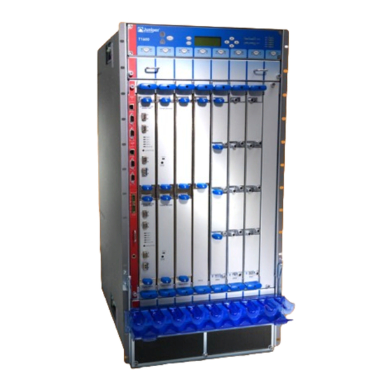
The T1600 router provides up to a total of 1600 million packets per second (Mpps) of forwarding. Figure 1 on page 4 and Figure 2 on page 5 illustrate the front and rear of a T1600 router. Copyright © 2010, Juniper Networks, Inc. - Page 28 T1600 Core Router Hardware Guide Figure 1: Front View of the T1600 Router Copyright © 2010, Juniper Networks, Inc.
- Page 29 Chapter 1: T1600 Router Overview Figure 2: Rear View of the T1600 Router Related T1600 System Architecture Description on page 7 Documentation T1600 Chassis Description on page 14 General Safety Guidelines for M Series, MX Series, and T Series Routers on page 309...
- Page 30 T1600 Core Router Hardware Guide Copyright © 2010, Juniper Networks, Inc.
-
Page 31: T1600 Router System Architecture Overview
T1600 System Architecture Description on page 7 T1600 Routing Engine Functions on page 8 T1600 Packet Forwarding Engine Architecture on page 9 Data Flow Through the T1600 Router on page 10 T1600 System Architecture Description The T1600 Core Router has two main architectural components: Routing Engine—This component provides Layer 3 routing services and network... -
Page 32: T1600 Routing Engine Functions
T1600 Core Router Hardware Guide T1600 Routing Engine Functions The Routing Engine handles all routing protocol processes, as well as the software processes that control the router's interfaces, the chassis components, system management, and user access to the router. These routing and software processes run on top of a kernel that interacts with the Packet Forwarding Engine. -
Page 33: T1600 Packet Forwarding Engine Architecture
Media-specific ASICs on the PICs that perform control functions tailored to the PIC media types. Related T1600 Flexible PIC Concentrator (FPC) Description on page 18 Documentation T1600 PIC Description on page 30 T1600 Chassis Description on page 14 T1600 Router Description on page 3 Copyright ©... -
Page 34: Data Flow Through The T1600 Router
Replacing T1600 Packet Forwarding Engine Components on page 237 Data Flow Through the T1600 Router To ensure the efficient movement of data through the T1600 router, the router is designed so that ASICs on the hardware components handle the forwarding of data. Data flows... - Page 35 Layer 2 encapsulation, and sends the packets to the outgoing PIC interface. The outgoing PIC sends the packets out into the network. Related T1600 Router Description on page 3 Documentation T1600 Chassis Description on page 14 T1600 Packet Forwarding Engine Architecture on page 9 Copyright © 2010, Juniper Networks, Inc.
- Page 36 T1600 Core Router Hardware Guide Copyright © 2010, Juniper Networks, Inc.
-
Page 37: T1600 Router Hardware Components Overview
T1600 Cooling System Description on page 69 T1600 Component Redundancy The T1600 Core Router is designed so that no single point of failure can cause the entire system to fail. The following major hardware components are redundant: Switch Interface Boards (SIBs)—The T1600 router has five SIBs. -
Page 38: T1600 Chassis Description
The T1600 Core Router chassis is a rigid sheet metal structure that houses all the other T1600 router components (see Figure 6 on page 15 and Figure 7 on page 16). The chassis measures 37.45 in. (95.1 cm) high, 31 in. (78.7 cm) deep, and 17.43 in. (44.3 cm) wide. The chassis can be installed into many types of racks or cabinets. - Page 39 Chapter 3: T1600 Router Hardware Components Overview your bare wrist. Failure to use an ESD strap could result in damage to the router. WARNING: The router must be connected to earth ground during normal operation. Figure 6: Front View of Router Chassis...
-
Page 40: T1600 Midplane Description
T1600 Core Router Hardware Guide Figure 7: Rear View of Router Chassis For chassis serial number information , see “Locating T1600 Component Serial Numbers Using the CLI” on page 373. Related T1600 Router Description on page 3 Documentation Rack Requirements for the T1600 Router on page 76... - Page 41 Signal path—The midplane provides the signal path to the FPCs, SIBs, Routing Engines, CB, and other system components for monitoring and control of the system. Figure 8: Midplane For chassis serial number information , see “Locating T1600 Component Serial Numbers Using the CLI” on page 373. Copyright © 2010, Juniper Networks, Inc.
-
Page 42: T1600 Flexible Pic Concentrator (Fpc) Overview
FPCs house the PICs that connect the T1600 Core Router to network media. The main function of an FPC is to connect the PICs installed in it to the other T1600 router components. The Packet Forwarding Engine receives incoming packets from the PICs installed on the FPC and forwards them through the switch planes to the appropriate destination port. -
Page 43: T1600 Fpc Terminology
Chapter 3: T1600 Router Hardware Components Overview Each Type 3 FPC has two Packet Forwarding Engines Each T640-FPC4-ES has one Packet Forwarding Engine Each T640-FPC4-1P-ES has one Packet Forwarding Engine Each T1600-FPC4-ES has two Packet Forwarding Engines Processor Mezzanine Board (PMB), which includes a 300-MHz CPU, system controller, 256 MB of SDRAM, and two Fast Ethernet interfaces. - Page 44 T1600 Core Router Hardware Guide Table 3: Identifying the FPCs Supported by the T1600 Router Location of PIC Offline Method of Securing the PIC Label on the FPC Faceplate Button to the FPC Enhanced FPC1 Slightly beneath the faceplate Two captive screws...
- Page 45 PIC faceplate The T1600 router supports the Enhanced Scaling FPC1, as shown in Figure 10 on page 21. Figure 10: Enhanced Scaling FPC1 Supported by the T1600 Router Copyright © 2010, Juniper Networks, Inc.
- Page 46 T1600 Core Router Hardware Guide The T1600 router supports the standard FPC2 and FPC3, as shown in Figure 11 on page 22. Figure 11: Standard FPC2 and FPC3 Supported by the T1600 Router FPC2 FPC3 Copyright © 2010, Juniper Networks, Inc.
- Page 47 Chapter 3: T1600 Router Hardware Components Overview The T1600 router supports the Enhanced II FPC1, FPC2, and FPC3, as shown inFigure 12 on page 23. Figure 12: Enhanced II FPC1, FPC2, and FPC3 Supported by the T1600 Router Copyright © 2010, Juniper Networks, Inc.
- Page 48 T1600 Core Router Hardware Guide The T1600 router supports the Enhanced Scaling FPC2, as shown in Figure 13 on page 24. Figure 13: Enhanced Scaling FPC2 Supported by the T1600 Router Copyright © 2010, Juniper Networks, Inc.
- Page 49 Chapter 3: T1600 Router Hardware Components Overview The T1600 router supports the Enhanced Scaling FPC3, as shown in Figure 14 on page 25. Figure 14: Enhanced Scaling FPC3 Supported by the T1600 Router Copyright © 2010, Juniper Networks, Inc.
- Page 50 T1600 Core Router Hardware Guide The T1600 router supports the T640 Enhanced Scaling FPC4, as shown in Figure 15 on page 26. Figure 15: T640 Enhanced Scaling FPC4 Supported by the T1600 Router Copyright © 2010, Juniper Networks, Inc.
- Page 51 Chapter 3: T1600 Router Hardware Components Overview The T1600 router supports the T640 Enhanced Scaling FPC4-1P, as shown in Figure 16 on page 27. Figure 16: T640 Enhanced Scaling FPC4-1P Supported by the T1600 Router Copyright © 2010, Juniper Networks, Inc.
-
Page 52: T1600 Fpcs Supported
Replacing a T1600 FPC on page 237 T1600 FPCs Supported T1600 Core Routers support the FPCs listed in Table 4 on page 29. You can install any combination of the following FPCs. First Junos OS Release supported indicates the first release that the FPC is supported in the T1600 router. - Page 53 Chapter 3: T1600 Router Hardware Components Overview Table 4: FPCs Supported by the T1600 Router Maximum First Junos OS FPC Model Throughput per Release Maximum FPC Type FPC Name Number Supported Number of PICs Enhanced FPC1 T640-FPC1-E 4 Gbps Standalone: 8.5 Routing matrix: 10.0...
-
Page 54: T1600 Pic Description
T1600 Core Router Hardware Guide Table 4: FPCs Supported by the T1600 Router (continued) Maximum First Junos OS FPC Model Throughput per Release Maximum FPC Type FPC Name Number Supported Number of PICs T640 Enhanced T640-FPC4-ES 50 Gbps Scaling FPC4... -
Page 55: Cable Management Systems
TXP-T1600 SIBs, and the cables connected to the LCC-CBs. The cables are routed to the left side of the T1600 router, and then toward the top of the chassis, where you can route the cables to the TX Matrix Plus router. The cable management system adds 9.5 in (24.1 cm) to the depth of the T1600 chassis, and 2.4 in... -
Page 56: T1600 Switch Interface Board (Sib) Overview
TXP-T1600 SIB LEDs on page 35 T1600 Switch Interface Board (SIB) Description SIBs create the switch fabric for the T1600 Core Router. Each T1600 router contains five SIBs located at the center rear of the chassis in the slots labeled... -
Page 57: T1600-Sib Description
NOTE: The TXP-T1600 SIB is required for connection to a TX Matrix Plus router. T1600-SIB Description Figure 20 on page 33 shows a T1600-SIB. T1600-SIBs are supported only on standalone T1600 routers. A T1600 router in a routing matrix does not support T1600-SIBs. Figure 20: T1600-SIB Each T1600-SIB consists of the following components: Switch fabric ASICs. -
Page 58: T1600-Sib Leds
T1600 Core Router Hardware Guide T1600-SIB LEDs Table 5 on page 34 describes the functions of the T1600-SIB LEDs. If all three LEDs are off, the SIB is not receiving power. The craft interface has three additional LEDs that show the status of each SIB. -
Page 59: Txp-T1600 Sib Leds
Chapter 3: T1600 Router Hardware Components Overview TXP-T1600 SIB LEDs Table 6 on page 35 describes the functions of the T1600-SIB LEDs. If all three LEDs are off, the SIB is not receiving power. The craft interface has three additional LEDs that show the status of each SIB. -
Page 60: T1600 Host Subsystem Overview
No optical power has been received. The fiber-optic array cable is not connected to the TXP-FI3 SIB port, or not connected to the TXP-T1600 SIB port. If the cable is connected on both sides, the cable might be cut. Related... -
Page 61: T1600 Routing Engine Overview
The Routing Engine runs the Junos OS. Software processes that run on the Routing Engine maintain the routing tables, manage the routing protocols used on the T1600 Core Router, control the T1600 router interfaces, control some chassis components, and provide the interface for system management and user access to the router. -
Page 62: T1600 Re-600 Description
NOTE: If two Routing Engines are installed, they must both be the same hardware model. The T1600 router supports these Routing Engines: RE-600 is supported in Junos OS Release 8.5 and later. RE-1600 is supported in Junos OS Release 8.5 and later. -
Page 63: T1600 Re-600 Leds
Routing Engine. You can also copy Junos OS from the Routing Engine onto a PC Card, for example, to create a backup copy of upgrade software that you have obtained from Juniper Networks. Instructions for copying software to a PC Card are available at the Juniper Networks Support Web site ( http://www.juniper.net/support/... -
Page 64: T1600 Re-1600 Description
NOTE: The LEDs that report host module status (including Routing Engine status) are on the craft interface rather than the Routing Engine faceplate. Related T1600 Routing Engine Description on page 37 Documentation T1600 RE-600 Description on page 38 T1600 RE-1600 Description... -
Page 65: T1600 Re-1600 Leds
Junos OS from the Routing Engine onto a PC Card, for example, to create a backup copy of upgrade software that you have obtained from Juniper Networks. Instructions for copying software to a PC Card are available at the Juniper Networks Support Web site ( http://www.juniper.net/support/... -
Page 66: T1600 Re-2000 Description
T1600 Core Router Hardware Guide Related T1600 Routing Engine Description on page 37 Documentation T1600 RE-1600 Description on page 40 T1600 RE-2000 Description The RE-2000 boots from the storage media in this order: the USB device, then the CompactFlash card (if present), then the hard disk, then the LAN. -
Page 67: T1600 Re-2000 Leds
Chapter 3: T1600 Router Hardware Components Overview Related T1600 Routing Engine Description on page 37 Documentation T1600 RE-2000 LEDs on page 43 T1600 RE-2000 LEDs Table 9 on page 43 describes the functions of the LEDs on the faceplate of the Routing Engine. -
Page 68: T1600 Re-C1800 Leds
, and SSD1 SSD2 ONLINE Related T1600 Routing Engine Description on page 37 Documentation T1600 RE-C1800 LEDs on page 44 T1600 RE-C1800 LEDs Figure 27 on page 44 shows the RE-C1800 LEDs. Table 10 on page 45 describes the functions of the LEDs on the faceplate of the Routing Engine. -
Page 69: T1600 Control Boards Overview
T1600 LCC-CB LEDs on page 48 T1600 Control Boards Description The T1600 chassis supports up to two control boards. The Routing Engine requires an adjacent control board to provide control and monitoring functions for the T1600 Core Router. These functions include determining Routing Engine mastership, controlling power and reset for the other T1600 router components, monitoring and controlling fan speed, and monitoring system status. -
Page 70: T1600 T Series Control Boards (T-Cbs) Description
The T1600 Core Router supports these control boards: The T Series control board (T-CB) is supported in Junos OS Release 8.5 and later. NOTE: The T-CB is required for a standalone T1600 router. The line-card chassis control board (LCC-CB) is supported Junos OS Release 9.6R2 and later. -
Page 71: T1600 T-Cb Leds
T-CB is powering up, but not online. – T-CB is offline. Related T1600 Host Subsystem Description on page 36 Documentation T1600 Control Boards Description on page 45 T1600 T Series Control Boards (T-CBs) Description on page 46 Copyright © 2010, Juniper Networks, Inc. -
Page 72: T1600 Line-Card Chassis Control Board (Lcc-Cb) Description
T1600 Line-Card Chassis Control Board (LCC-CB) Description The LCC-CBs (see Figure 29 on page 48) must be installed before you can connect a T1600 router to a TX Matrix Plus Router. Each LCC-CB consists of the following components: 100-MB Ethernet switch for intermodule communication. - Page 73 Chapter 3: T1600 Router Hardware Components Overview Figure 30: LCC-CB LEDs Link Activity The LEDs located in the middle of the LCC-CB indicate its status.Table 12 on page 49 describes the functions of the LCC-CB LEDs. Table 12: LCC-CB LEDs...
-
Page 74: T1600 Sonet Clock Generators (Scgs) Description
T1600 Host Subsystem Description on page 36 Documentation T1600 Control Boards Description on page 45 T1600 Line-Card Chassis Control Board (LCC-CB) Description on page 48 T1600 SONET Clock Generators (SCGs) Description The SONET Clock Generators (SCGs) provide 19.44-MHz Stratum 3 clock signal for the SONET/SDH interfaces on the router (see Figure 31 on page 50). -
Page 75: T1600 Scg Leds
The craft interface allows you to view status and troubleshooting information at a glance and to perform many system control functions. It is hot-insertable and hot-removable. The craft interface is located on the front of the T1600 Core Router above the FPCs (see Figure 32 on page 52). -
Page 76: T1600 Craft Interface Alarm Leds And Aco/Lt Button
Related T1600 Craft Interface LCD and Navigation Buttons on page 53 Documentation T1600 Craft Interface Alarm LEDs and ACO/LT Button on page 52 T1600 Craft Interface Host Subsystem LEDs on page 54 T1600 Craft Interface SIB LEDs on page 55... -
Page 77: T1600 Craft Interface Lcd And Navigation Buttons
Documentation T1600 Alarm Relay Contacts on page 58 T1600 Craft Interface LCD and Navigation Buttons on page 53 T1600 Craft Interface LCD and Navigation Buttons A four-line LCD is located in the craft interface, along with six navigation buttons. The... -
Page 78: T1600 Craft Interface Host Subsystem Leds
) or yellow ( alarm. For a list of alarm messages that can appear on the LCD, see . Related T1600 Craft Interface Description on page 51 Documentation T1600 Alarm Messages Overview on page 175 T1600 Craft Interface Host Subsystem LEDs Each host subsystem has three LEDs, located on the upper right of the craft interface, that indicate its status. -
Page 79: T1600 Craft Interface Sib Leds
FAIL Green On steadily SIB is functioning normally. Related T1600 Switch Interface Board (SIB) Description on page 32 Documentation T1600 Craft Interface Description on page 51 Maintaining the T1600 SIBs on page 168 Replacing a T1600-SIB on page 230 T1600 Craft Interface FPC LEDs Each FPC slot has two LEDs that indicate its status. -
Page 80: T1600 Connector Interface Panel (Cip) Overview
T1600 Core Router Hardware Guide Related T1600 Flexible PIC Concentrator (FPC) Description on page 18 Documentation T1600 Craft Interface Description on page 51 Maintaining T1600 FPCs on page 156 Troubleshooting the T1600 FPCs on page 184 Replacing a T1600 FPC on page 237... -
Page 81: Routing Engine Ports
Chapter 3: T1600 Router Hardware Components Overview Figure 35: CIP Routing Engine Ports The CIP has two sets of ports (see Figure 35 on page 57) that you use to connect the Routing Engines to external management devices. The upper set of ports, labeled... -
Page 82: T1600 Alarm Relay Contacts
Replacing a T1600 CIP on page 192 T1600 Routing Engine Interface Cable and Wire Specifications on page 369 T1600 RJ-45 Connector Pinouts for the Routing Engine ETHERNET Port on page 371 T1600 DB-9 Connector Pinouts for the Routing Engine AUXILIARY and CONSOLE Ports... -
Page 83: T1600 Power System Description
T1600 Three-Phase Delta and Wye AC Power Supply Overview on page 65 T1600 Three-Phase Delta and Wye AC Power Supply LEDs on page 68 T1600 Power System Description The T1600 Core Router has two redundant, load-sharing power supplies, located at the lower rear of the chassis in slots (top to bottom). -
Page 84: T1600 Three-Input 240-A Dc Power Supply Description
FPC3 T1600 Three-Input 240-A DC Power Supply Load Sharing and Fault Tolerance When the T1600 router is operating normally and both power supplies are switched on, load sharing between them occurs automatically. When one power supply fails or is turned off, the other power supply immediately assumes the entire electrical load for the system. -
Page 85: T1600 Three-Input 240-A Dc Power Supply Leds
Related T1600 Power System Description on page 59 Documentation T1600 Three-Input 240-A DC Power Supply LEDs on page 61 T1600 DC Power Requirements on page 352 Troubleshooting the T1600 Power System on page 185 T1600 Three-Input 240-A DC Power Supply LEDs LEDs on each power supply faceplate (see Table 21 on page 62) indicate the status of the power supply. -
Page 86: T1600 Four-Input 240-A Dc Power Supply Overview
T1600 DC Power Requirements on page 352 Troubleshooting the T1600 Power System on page 185 Replacing a T1600 Three-Input 240-A DC Power Supply on page 259 T1600 Four-Input 240-A DC Power Supply Overview Four-Input 240-A DC Power Supply Description on page 62... -
Page 87: Four-Input 240-A Dc Power Supply Inputs
Related T1600 Power System Description on page 59 Documentation T1600 Four-Input 240-A DC Power Supply LEDs on page 64 T1600 DC Power Requirements on page 352 Troubleshooting the T1600 Power System on page 185 Copyright © 2010, Juniper Networks, Inc. -
Page 88: T1600 Four-Input 240-A Dc Power Supply Leds
Power supply has exceeded —One per recommended temperature. TEMP power supply Power supply is within the recommended temperature or the power supply is not on. Related T1600 Four-Input 240-A DC Power Supply Overview on page 62 Documentation Copyright © 2010, Juniper Networks, Inc. -
Page 89: T1600 Three-Phase Delta And Wye Ac Power Supply Overview
T1600 DC Power Requirements on page 352 Troubleshooting the T1600 Power System on page 185 Replacing a T1600 Four-Input 240-A DC Power Supply on page 269 T1600 Three-Phase Delta and Wye AC Power Supply Overview Three-Phase Delta AC Power Supply Description on page 65... -
Page 90: Three-Phase Wye Ac Power Supply Description
T1600 Core Router Hardware Guide Figure 41: Three-Phase Delta AC Power Supply Connections L2 L3 L2 L3 Figure 42 on page 66 shows the three-phase delta AC power cord. Figure 42: Three-Phase Delta AC Power Cord Three-Phase Wye AC Power Supply Description Each three-phase wye AC power supply weighs approximately 31.0 lb. -
Page 91: Ac Power Supply Load Sharing And Fault Tolerance
Chapter 3: T1600 Router Hardware Components Overview Figure 43: Three-Phase Wye AC Power Supply Figure 44 on page 67 shows the three-phase wye AC power supply connections. Figure 44: Three-Phase Wye AC Power Supply Connections L2 L3 Figure 45 on page 67 shows the three-phase wye AC power cord. -
Page 92: T1600 Three-Phase Delta And Wye Ac Power Supply Leds
Related T1600 Power System Description on page 59 Documentation T1600 Three-Phase Delta and Wye AC Power Supply LEDs on page 68 Troubleshooting the T1600 Power System on page 185 T1600 AC Power Requirements on page 358 T1600 AC Power Cord Specifications on page 360... -
Page 93: T1600 Cooling System Description
LED indicates that power supply is within the recommended temperature. Related T1600 Three-Phase Delta and Wye AC Power Supply Overview on page 65 Documentation Troubleshooting the T1600 Power System on page 185 T1600 AC Power Requirements on page 358... - Page 94 Each power supply contains one fan that cools that power supply. All fan trays and filters are hot-insertable and hot-removable. Related Troubleshooting the T1600 Cooling System on page 182 Documentation T1600 Router Description on page 3 Copyright © 2010, Juniper Networks, Inc.
- Page 95 Installing the T1600 Router Mounting Hardware on page 85 Installing the T1600 Router into the Rack on page 93 Installing the T1600 Router Using a Mechanical Lift on page 95 Installing the T1600 Router Without a Mechanical Lift on page 101...
- Page 96 T1600 Core Router Hardware Guide Copyright © 2010, Juniper Networks, Inc.
-
Page 97: T1600 Router Installation Summary
85 or “Installing the T1600 Mounting Hardware for an Open-Frame Rack” on page 89. Install the router See “Mounting the T1600 Chassis Using a Mechanical Lift” on page 98 or “Installing the T1600 Chassis in the Rack Manually” on page 112. Perform the initial system startup. - Page 98 T1600 Core Router Hardware Guide Copyright © 2010, Juniper Networks, Inc.
-
Page 99: Preparing For T1600 Router Installation
T1600 Site Preparation Requirements Checklist on page 75 Rack Requirements for the T1600 Router on page 76 Clearance Requirements for Airflow and T1600 Hardware Maintenance on page 77 T1600 Site Preparation Requirements Checklist The checklist in Table 25 on page 75 summarizes the tasks you need to perform when preparing a site for router installation. -
Page 100: Rack Requirements For The T1600 Router
“Maintaining T1600 PICs and PIC Cables” on page 166 Rack Requirements for the T1600 Router The router can be installed in many types of racks, including four-post (telco) racks and open-frame racks. An example of an open-frame rack is shown in Figure 48 on page 77. -
Page 101: Clearance Requirements For Airflow And T1600 Hardware Maintenance
For maximum stability, also secure the rack to ceiling brackets. Related Clearance Requirements for Airflow and T1600 Hardware Maintenance on page 77 Documentation Before You Install the T1600 Rack-Mounting Hardware Installation Safety Warnings for M Series, MX Series, and T Series Routers on page 317... - Page 102 Related T1600 Chassis Description on page 14 Documentation T1600 Rear Cable Management System Description on page 31 T1600 Cooling System Description on page 69 Rack Requirements for the T1600 Router on page 76 Copyright © 2010, Juniper Networks, Inc.
-
Page 103: Unpacking The T1600 Router
Overview of Unpacking the T1600 Router To unpack the router: Gather the tools required to unpack the router. See “Tools and Parts Required to Unpack the T1600 Router” on page 79. Unpack the router. See “Unpacking the T1600 Router” on page 80. -
Page 104: Unpacking The T1600 Router
T1600 Core Router Hardware Guide Unpacking the T1600 Router The router is shipped in a wooden crate. A wooden pallet forms the base of the crate. The router chassis is bolted to this pallet. Quick Start installation instructions and a cardboard accessory box are also included in the shipping crate. -
Page 105: Verifying The T1600 Router Parts Received
Related Verifying the T1600 Router Parts Received on page 81 Documentation Mounting the T1600 Chassis Using a Mechanical Lift on page 98 Installing the T1600 Chassis in the Rack Manually on page 112 T1600 Router Description on page 3 Verifying the T1600 Router Parts Received A packing list is included in each shipment. - Page 106 T1600 Core Router Hardware Guide Table 26: Router Parts List (continued) Component Quantity SIBs Routing Engines 1 or 2 Control boards 1 or 2 (one for each Routing Engine) SCGs 1 or 2 Power supplies Front fan trays Rear fan tray...
- Page 107 Serial cable, 6-ft length, to connect Routing Engine to management console End User License Agreement Related T1600 Router Description on page 3 Documentation Overview of Unpacking the T1600 Router on page 79 Unpacking the T1600 Router on page 80 Copyright © 2010, Juniper Networks, Inc.
- Page 108 T1600 Core Router Hardware Guide Copyright © 2010, Juniper Networks, Inc.
-
Page 109: Installing The T1600 Router Mounting Hardware
Installing the T1600 Router Mounting Hardware Installing the T1600 Mounting Hardware for a Four-Post Rack or Cabinet on page 85 Installing the T1600 Mounting Hardware for an Open-Frame Rack on page 89 Installing the T1600 Mounting Hardware for a Four-Post Rack or Cabinet... -
Page 110: Installing The Large Mounting Shelf
T1600 Core Router Hardware Guide Table 28: Four-Post or Cabinet Rack Mounting Hole Locations (continued) Large Spacer Small Hole Distance Above “U” Division Shelf Bars Shelf 19.01 in. (48.3 cm) 10.86 U 13.76 in. (34.9 cm) 7.86 U 8.51 in. (21.6 cm) 4.86 U... -
Page 111: Installing The Small Shelf
Chapter 7: Installing the T1600 Router Mounting Hardware Figure 51: Installing the Mounting Hardware for a Four-Post Rack or Cabinet Installing the Small Shelf To install the small shelf: On the back of each rear rack rail, partially insert a mounting screw into the lowest hole specified in Table 28 on page 85 for the small shelf. -
Page 112: Installing The Spacer Bars
T1600 Core Router Hardware Guide Installing the Spacer Bars The router is shipped with each spacer bar attached to the rear of each front-mounting flange. To install the spacer bars: Remove each spacer bar by removing the screws that fasten the spacer bar to the front-mounting flange. -
Page 113: Installing The T1600 Mounting Hardware For An Open-Frame Rack
Related T1600 Router Description on page 3 Documentation Overview of Installing the T1600 Router on page 73 T1600 Site Preparation Requirements Checklist on page 75 Installing the T1600 Mounting Hardware for an Open-Frame Rack In an open-frame rack, center-mounting is generally preferable to front-mounting because the more even distribution of weight provides greater stability. -
Page 114: Installing The Cage Nuts, If Needed
T1600 Core Router Hardware Guide the chassis, you use the front-mounting flanges, and must remove the center-mounting brackets. Installing the Cage Nuts, if Needed on page 90 Installing the Large Mounting Shelf on page 90 Removing the Center-Mounting Brackets from the Chassis on page 91... -
Page 115: Removing The Center-Mounting Brackets From The Chassis
Chapter 7: Installing the T1600 Router Mounting Hardware Figure 54: Installing the Mounting Hardware for an Open-Frame Rack Removing the Center-Mounting Brackets from the Chassis Before front-mounting the router in an open-frame rack, you must remove the center-mounting brackets from the chassis. -
Page 116: Removing The Spacer Bars
Remove the screws that fasten the spacer bar to the front-mounting flange Remove the spacer bars. Related T1600 Router Description on page 3 Documentation Overview of Installing the T1600 Router on page 73 T1600 Site Preparation Requirements Checklist on page 75 Copyright © 2010, Juniper Networks, Inc. -
Page 117: Installing The T1600 Router Into The Rack
Verify that the site has been prepared for the router installation. See “T1600 Site Preparation Requirements Checklist” on page 75. Because of the T1600 router's size and weight—up to 606 lb (275 kg) fully configured—we strongly recommend that you lift the router into the rack using a mechanical lift. - Page 118 T1600 Core Router Hardware Guide Copyright © 2010, Juniper Networks, Inc.
-
Page 119: Installing The T1600 Router Using A Mechanical Lift
Installing the T1600 Router Using a Mechanical Lift on page 96 Overview of Installing a T1600 Router Using a Mechanical Lift Because of the T1600 router's size and weight—up to 606 lb (275 kg) depending on the configuration—we strongly recommend that you install the router using a mechanical lift. -
Page 120: Tools Required To Install The T1600 Router Using A Mechanical Lift
T1600 Core Router Hardware Guide Tools Required to Install the T1600 Router Using a Mechanical Lift To install the T1600 router using a mechanical lift, you need the following tools: Mechanical lift Phillips (+) screwdrivers, number 2 Related T1600 Router Description on page 3... -
Page 121: Attaching The T1600 Installation Handle
Chapter 9: Installing the T1600 Router Using a Mechanical Lift Place one hand underneath the power supply to support it and slide it completely out of the chassis. Repeat the procedure for the other power supply. Figure 56: Removing a Three-Input 240-A DC Power Supply... -
Page 122: Mounting The T1600 Chassis Using A Mechanical Lift
Ensure that the installation site allows adequate clearance for both airflow and maintenance. For details, see “Clearance Requirements for Airflow and T1600 Hardware Maintenance” on page 77. Load the router onto the lift, making sure it rests securely on the lift platform. -
Page 123: Supplies
Chapter 9: Installing the T1600 Router Using a Mechanical Lift Figure 58: Installing the Router in the Rack NOTE: This illustration depicts the router being installed in a four-post rack.. Removing the T1600 Installation Handle and Reinstalling the Power Supplies... - Page 124 T1600 Core Router Hardware Guide Tighten the captive screws at the lower corners of the power supply faceplate to secure the power supply in the chassis. Repeat the procedure for the upper power supply. Figure 59: Reinstalling a Three-Input 240-A DC Power Supply Figure 60: Reinstalling a Four-Input 240-A DC Power Supply Copyright ©...
-
Page 125: Installing The T1600 Router Without A Mechanical Lift
Reinstalling the T1600 Components in the Chassis on page 115 Overview of Installing a T1600 Router Without a Mechanical Lift If you cannot use a mechanical lift to install the T1600 router (the preferred method), you can install it manually. -
Page 126: Removing Components From The T1600 Chassis
See “Removing Components from the T1600 Chassis” on page 102. Install the T1600 Chassis in the Rack Manually. At least four people are needed to safely lift the chassis into the rack or cabinet. With components removed, the chassis weighs approximately 225 lb (102 kg). -
Page 127: Removing The T1600 Dc Power Supplies
Chapter 10: Installing the T1600 Router Without a Mechanical Lift Removing the T1600 Front Cable Management System on page 109 Removing the T1600 Standard Front Fan Trays on page 110 Removing the T1600 FPCs on page 110 Removing the T1600 DC Power Supplies The power supplies are located at the rear of the chassis below the SIBs. -
Page 128: Removing The T1600 Ac Power Supplies
Figure 62: Removing a Four-Input 240-A Power Supply Before Installing the Router Removing the T1600 AC Power Supplies The power supplies are located at the rear of the chassis below the SIBs. Each three-phase delta AC power supply weighs approximately 25 lb (11.3 kg). Each three-phase wye AC power supply weighs approximately 26.6 lb. -
Page 129: Removing The T1600 Sibs
Chapter 10: Installing the T1600 Router Without a Mechanical Lift Figure 63: Removing a Three-Phase Delta AC Power Supply Before Installing the Router Figure 64: Removing a Three-Phase Wye AC Power Supply Before Installing the Router Removing the T1600 SIBs Five SIBs are installed in the router. -
Page 130: Removing The T1600 Control Boards
T1600 Core Router Hardware Guide Grasp both ejector handles, pull firmly, and slide the SIB about three-quarters of the way out of the chassis. Place one hand underneath the SIB to support it and slide it completely out of the chassis. -
Page 131: Removing The T1600 Scgs
Chapter 10: Installing the T1600 Router Without a Mechanical Lift Place one hand underneath the control board to support it and slide it completely out of the chassis. Place it on the antistatic mat. CAUTION: Do not stack hardware components on one another after you remove them. -
Page 132: Removing The T1600 Standard Rear Fan Tray
T1600 Core Router Hardware Guide Figure 67: Removing an SCG Removing the T1600 Standard Rear Fan Tray The rear fan tray is mounted vertically on the right side of the rear of the chassis. The standard rear fan tray contains eight fans. The standard fan tray weighs about 10 lb (4.5 kg). -
Page 133: Removing The T1600 Front Cable Management System
Chapter 10: Installing the T1600 Router Without a Mechanical Lift Figure 68: Removing the T1600 Rear Fan Tray Removing the T1600 Front Cable Management System The front cable management system is located below the FPC card cage. The cable management system weighs approximately 5 lb (2.3 kg). -
Page 134: Removing The T1600 Standard Front Fan Trays
T1600 Core Router Hardware Guide Removing the T1600 Standard Front Fan Trays The upper front fan tray is located above the FPC card cage, and the lower front fan tray is located below the air filter. Each standard front fan tray weighs about 18.6 lb (8.4 kg). - Page 135 Chapter 10: Installing the T1600 Router Without a Mechanical Lift If you are removing a Type 2 FPC or Type 3 FPC, loosen the screws inside the ejector handles at the top and bottom of the FPC faceplate. Simultaneously turn both the ejector handles counterclockwise to unseat the FPC.
-
Page 136: Installing The T1600 Chassis In The Rack Manually
Related T1600 Preventing Electrostatic Discharge Damage on page 312 Documentation T1600 Front Cable Management System Description on page 31 Holding and Storing T1600 FPCs Maintaining the T1600 Fan Trays on page 153 Installing the T1600 Chassis in the Rack Manually... - Page 137 If you are installing the router in an open-frame rack, ensure that the rack is in its permanent location and is secured to the building. Ensure that the installation site allows adequate clearance for both airflow and maintenance. For details, see “T1600 Site Preparation Requirements Checklist” on page 75.
- Page 138 T1600 Core Router Hardware Guide WARNING: To prevent injury, keep your back straight and lift with your legs, not your back. Avoid twisting your body as you lift. Balance the load evenly and be sure that your footing is solid.
-
Page 139: Reinstalling The T1600 Components In The Chassis
Overview of Installing the T1600 Router on page 73 Documentation Overview of Installing a T1600 Router Without a Mechanical Lift on page 101 T1600 Chassis Lifting Guidelines on page 316 Reinstalling the T1600 Components in the Chassis on page 115... -
Page 140: Reinstalling The T1600 Rear Fan Tray
Reinstalling the T1600 FPCs on page 121 Reinstalling T1600 Front Fan Trays on page 122 Reinstalling the T1600 Front Cable Management System on page 123 Reinstalling the T1600 Rear Fan Tray To reinstall the standard rear fan tray (see Figure 73 on page 116): Attach an electrostatic discharge (ESD) grounding strap to your bare wrist, and connect the strap to an approved site ESD grounding point. -
Page 141: Reinstalling The T1600 Scgs
Chapter 10: Installing the T1600 Router Without a Mechanical Lift Reinstalling the T1600 SCGs To reinstall the SCGs (see Figure 74 on page 117): Attach an electrostatic discharge (ESD) grounding strap to your bare wrist, and connect the strap to an approved site ESD grounding point. See the instructions for your site. -
Page 142: Reinstalling The T1600 Sibs
T1600 Core Router Hardware Guide Figure 75: Reinstalling a T-CB Figure 76: Reinstalling an LCC-CB Reinstalling the T1600 SIBs To reinstall the SIBs (see Figure 77 on page 119): Attach an electrostatic discharge (ESD) grounding strap to your bare wrist, and connect the strap to an approved site ESD grounding point. -
Page 143: Reinstalling The T1600 Power Supplies
Chapter 10: Installing the T1600 Router Without a Mechanical Lift Tighten the captive screws on the ejector handles. Repeat the procedure for each of the remaining SIBs. Figure 77: Reinstalling a T1600–SIB Reinstalling the T1600 Power Supplies Reinstalling the T1600 DC Power Supplies on page 119... -
Page 144: Reinstalling The T1600 Ac Power Supplies
T1600 Core Router Hardware Guide Figure 78: Reinstalling a Three-Input 240-A DC Power Supply Figure 79: Reinstalling a T1600 Four-Input 240-A DC Power Supply Reinstalling the T1600 AC Power Supplies You can use this procedure to reinstall either the three-phase delta or wye AC power supplies. -
Page 145: Reinstalling The T1600 Fpcs
Chapter 10: Installing the T1600 Router Without a Mechanical Lift Reinstalling the T1600 FPCs To reinstall FPCs (see Figure 80 on page 122): Attach an electrostatic discharge (ESD) grounding strap to your bare wrist, and connect the strap to an approved site ESD grounding point. See the instructions for your site. -
Page 146: Reinstalling T1600 Front Fan Trays
T1600 Core Router Hardware Guide Figure 80: Reinstalling an FPC Reinstalling T1600 Front Fan Trays To reinstall the standard front fan trays (see Figure 81 on page 123): Attach an electrostatic discharge (ESD) grounding strap to your bare wrist, and connect the strap to an approved site ESD grounding point. -
Page 147: Reinstalling The T1600 Front Cable Management System
Overview of Installing the T1600 Router on page 73 Documentation Overview of Installing a T1600 Router Without a Mechanical Lift on page 101 Removing Components from the T1600 Chassis on page 102 T1600 Preventing Electrostatic Discharge Damage on page 312... - Page 148 T1600 Core Router Hardware Guide Copyright © 2010, Juniper Networks, Inc.
-
Page 149: Grounding The T1600 Router
CHAPTER 11 Grounding the T1600 Router Tools and Parts Required to Ground the T1600 Router on page 125 Connecting the T1600 Grounding Cable on page 125 Tools and Parts Required to Ground the T1600 Router To ground the router, you need:... - Page 150 Related T1600 Chassis Description on page 14 Documentation Tools and Parts Required to Ground the T1600 Router on page 125 T1600 Chassis Grounding Cable and Lug Specifications on page 362 T1600 Preventing Electrostatic Discharge Damage on page 312 Copyright © 2010, Juniper Networks, Inc.
-
Page 151: Connecting The T1600 Router To External Devices
CHAPTER 12 Connecting the T1600 Router to External Devices Tools and Parts Required to Connect the T1600 Router to External Devices on page 127 Overview of Connecting the T1600 Router to Management and Alarm Devices on page 127 Connecting the T1600 Router to Management and Alarm Devices on page 128... -
Page 152: Connecting The T1600 Router To Management And Alarm Devices
Connecting the T1600 Router to Management and Alarm Devices Connecting the T1600 Router to a Network for Out-of-Band Management on page 129 Connecting the T1600 Router to a Management Console or Auxiliary Device on page 129 Copyright © 2010, Juniper Networks, Inc. -
Page 153: Connecting The T1600 Router To A Network For Out-Of-Band Management
Chapter 12: Connecting the T1600 Router to External Devices Connecting the T1600 Router to an External Alarm-Reporting Device on page 130 Connecting PIC Cables to the T1600 Router on page 130 Connecting the T1600 Router to a Network for Out-of-Band Management... -
Page 154: Connecting The T1600 Router To An External Alarm-Reporting Device
T1600 Core Router Hardware Guide Connecting the T1600 Router to an External Alarm-Reporting Device To connect the router to external alarm-reporting devices, attach wires to the RED ALARM YELLOW ALARM relay contacts on the CIP. A system condition that triggers the red or yellow alarm LED on the craft interface also activates the corresponding alarm relay contact. - Page 155 Chapter 12: Connecting the T1600 Router to External Devices CAUTION: Do not leave a fiber-optic transceiver uncovered except when inserting or removing cable. The safety cap keeps the port clean and prevents accidental exposure to laser light. Insert the cable connector into the cable connector port on the PIC faceplate.
- Page 156 T1600 Core Router Hardware Guide Overview of Connecting the T1600 Router to Management and Alarm Devices on page 127 Replacing the T1600 Alarm Relay Wires on page 198 T1600 Front Cable Management System Description on page 31 Copyright © 2010, Juniper Networks, Inc.
-
Page 157: Providing Power To The T1600 Router
CHAPTER 13 Providing Power to the T1600 Router Tools and Parts Required to Provide Power to the T1600 Router on page 133 Connecting DC Power to the T1600 Router on page 134 Powering On the DC-Powered T1600 Router on page 136... -
Page 158: Connecting Dc Power To The T1600 Router
T1600 Core Router Hardware Guide T1600 AC Power Requirements on page 358 Connecting DC Power to the T1600 Router You connect DC power to the router by attaching power cables from the DC power sources to the terminal studs on the power supply faceplates. You must provide power cables (the cable lugs are supplied with the router). - Page 159 Chapter 13: Providing Power to the T1600 Router CAUTION: You must ensure that power connections maintain the proper polarity. The power source cables might be labeled to indicate (–) their polarity. There is no standard color coding for DC power cables. The...
-
Page 160: Powering On The Dc-Powered T1600 Router
T1600 DC Power Cables and Lugs on page 354 Powering On the DC-Powered T1600 Router You can use this procedure for a T1600 router for either three-input 240-A DC power supplies or four-input 240-A DC power supplies. To power on the DC-powered router: Verify that the power supplies are fully inserted in the chassis and that the captive screws on their faceplates are tightened. - Page 161 DC OK momentarily, then lights steadily. Repeat the procedure for the other power supply. Related Overview of Connecting the T1600 Router to Management and Alarm Devices on Documentation page 127. Connecting DC Power to the T1600 Router on page 134...
-
Page 162: Supplies
T1600 General Electrical Safety Guidelines on page 330 T1600 DC Power System Electrical Specifications on page 349 Connecting AC Power to a T1600 Router with Three-Phase Delta AC Power Supplies You connect AC power to the router with three-phase delta AC power supplies by connecting the AC power cord from an AC power supply to an AC power source. - Page 163 Chapter 13: Providing Power to the T1600 Router Connect the wires to the AC terminal block on the three-phase delta AC power supply (Figure 88 on page 139). Use 1/4-in. slotted screwdriver to loosen the input terminal or grounding point screw, insert each wire into the grounding point or input terminal, and tighten the screw.
-
Page 164: Supplies
T1600 AC Power Cord Specifications on page 360 T1600 Preventing Electrostatic Discharge Damage on page 312 Connecting AC Power to a T1600 Router with Three-Phase Wye AC Power Supplies To connect an AC power cord: Attach an electrostatic discharge (ESD) grounding strap to your bare wrist, and connect the strap to an approved site ESD grounding point. - Page 165 Chapter 13: Providing Power to the T1600 Router Connect the wires to the AC terminal block on the three-phase wye AC power supply (Figure 89 on page 141). Use a 1/4-in. slotted screwdriver to unscrew each of the input terminals or grounding point, insert each wire into the grounding point or input terminal, and tighten the screw.
-
Page 166: Powering On The Ac-Powered T1600 Router
T1600 Core Router Hardware Guide Related T1600 Three-Phase Delta and Wye AC Power Supply Overview on page 65 Documentation Powering On the AC-Powered T1600 Router on page 142 T1600 General Electrical Safety Guidelines on page 330 T1600 AC Power Electrical Safety Guidelines on page 339... -
Page 167: Powering Off The T1600 Router
Overview of Connecting the T1600 Router to Management and Alarm Devices on page 127 Connecting AC Power to a T1600 Router with Three-Phase Delta AC Power Supplies on page 138 Connecting AC Power to a T1600 Router with Three-Phase Wye AC Power Supplies... - Page 168 Switch the circuit breakers on each DC power supply faceplate to the off position ( or switch the power switch on each AC power supply faceplate to the standby position. Related T1600 Preventing Electrostatic Discharge Damage on page 312 Documentation T1600 General Electrical Safety Guidelines on page 330...
-
Page 169: Configuring The Junos Os
The T1600 router is shipped with the Junos OS preinstalled and ready to be configured when the T1600 router is powered on. There are three copies of the software: one on a CompactFlash card in the Routing Engine, one on a rotating hard disk in the Routing Engine, and one on a PC Card that can be inserted into the slot in the Routing Engine faceplate. - Page 170 T1600 Core Router Hardware Guide Start the CLI. root# cli root@> Enter configuration mode. cli> configure [edit] root@# Configure the name of the router. If the name includes spaces, enclose the name in quotation marks (“ ”). [edit] root@# set system host-name host-name Create a management console user account.
- Page 171 (Optional) Configure additional properties by adding the necessary configuration statements. Then commit the changes to activate them on the router. [edit] root@host# commit When you have finished configuring the router, exit configuration mode. Copyright © 2010, Juniper Networks, Inc.
- Page 172 OS displays a message indication this when you log in to the router. Related Powering On the DC-Powered T1600 Router on page 136 Documentation Powering On a Replacement T1600 Three-Input 240-A Power Supply on page 269 T1600 Chassis Description on page 14 Copyright © 2010, Juniper Networks, Inc.
- Page 173 PART 3 T1600 Router Hardware Maintenance, Troubleshooting, and Replacement Procedures Maintaining T1600 Router Hardware Components on page 151 Troubleshooting T1600 Router Hardware Components on page 173 Replacing T1600 Router Hardware Components on page 189 Copyright © 2010, Juniper Networks, Inc.
- Page 174 T1600 Core Router Hardware Guide Copyright © 2010, Juniper Networks, Inc.
-
Page 175: Maintaining T1600 Router Hardware Components
CHAPTER 15 Maintaining T1600 Router Hardware Components Tools and Parts Required to Maintain the T1600 Hardware Components on page 151 Routine Maintenance Procedures for the T1600 Router on page 151 Maintaining Cooling System Components on page 152 Maintaining the T1600 Host Subsystem on page 154... -
Page 176: Maintaining Cooling System Components
Action On a regular basis, check the vents and clean them as necessary. Related Clearance Requirements for Airflow and T1600 Hardware Maintenance on page 77 Documentation T1600 Cooling System Description on page 69 Maintaining the T1600 Air Filters Purpose For optimum cooling, verify the condition of the air filters. -
Page 177: Maintaining The T1600 Fan Trays
Check the air filters regularly for dust and debris. The filter elements degrade over time, so the filter elements in use, must be replaced every 6 months. For procedures to replace the air filters, see “Replacing the T1600 Rear Air Filter” on page 208 and “Replacing the T1600 Front Air Filter” on page 206. -
Page 178: Maintaining The T1600 Host Subsystem
LED is lit, look at the LCD to get more information about the cause of the problem. For more information about the LEDs and the display, see “T1600 Craft Interface Description” on page 51 To maintain the Routing Engines and control boards:... -
Page 179: Maintaining The T1600 Control Boards
Check the host subsystem LEDs on the craft interface. For more information about the LEDs and the display, see “T1600 Craft Interface Description” on page 51. Check the LCD on the craft interface to view information about the router temperature and the status of the Routing Engines. -
Page 180: Maintaining The T1600 Scgs
For optimum router performance, verify the condition of the SCGs. Action On a regular basis: Check the SCG LEDs. For more information, see “T1600 SCG LEDs” on page 51. Issue the command to display information about the show chassis environment scg SCGs. -
Page 181: Cleaning Fiber-Optic Array Components With The Dry Cloth Cleaning Tool
T1600 Flexible PIC Concentrator (FPC) Description on page 18 Cleaning Fiber-Optic Array Components with the Dry Cloth Cleaning Tool Note: This procedure is required only for TX Matrix Plus components and T1600 routers in a routing matrix. It is not required for fiber-optic ports on the PICs. - Page 182 ONLINE/OFFLINE Disconnect the fiber-optic array cable between the TXP-F13 SIB and TXP-T1600 SIB. WARNING: Do not look directly into a fiber-optic array port or a connector at the end of a fiber-optic array cable connected to a port. The fiber optics emit laser light that can damage your eyes.
- Page 183 NOTE: This illustration shows TXP-F13 SIBs on a TX Matrix Plus router. However, the method for inserting the cleaning tool adapter and cleaning tool is the same for the TXP-T1600 SIB. NOTE: The cleaning adapter is keyed to ensure that the cleaning tip can be inserted in only one way.
- Page 184 Verify that the state of each optical link is Links ok If the state of any TXP-F13 SIB, TXP-T1600 SIB, or link is still incorrect, contact your customer support representative for additional instructions. Copyright © 2010, Juniper Networks, Inc.
-
Page 185: Holding And Storing T1600 Fpcs
Chapter 15: Maintaining T1600 Router Hardware Components Holding and Storing T1600 FPCs Holding T1600 FPCs on page 161 Storing T1600 FPCs on page 165 Holding T1600 FPCs Preventing Damage to FPCs on page 161 Holding T1600 FPCs Vertically on page 163... - Page 186 T1600 Core Router Hardware Guide Figure 96: Do Not Grasp the Connector Edge Figure 97: Do Not Carry an FPC with Only One Hand Copyright © 2010, Juniper Networks, Inc.
-
Page 187: Holding T1600 Fpcs Vertically
Chapter 15: Maintaining T1600 Router Hardware Components Figure 98: Do Not Rest the FPC on an Edge Holding T1600 FPCs Vertically NOTE: An FPC configured with PICs installed can weigh as much as 37 lb (14.5 kg). Be prepared to accept the full weight of the FPC as you lift it. -
Page 188: Holding T1600 Fpcs Horizontally
T1600 Core Router Hardware Guide Figure 99: Holding an FPC Vertically Holding T1600 FPCs Horizontally To hold an FPC horizontally: Orient the FPC so that the faceplate is facing you. Grasp the top edge with your left hand and the bottom edge with your right hand. -
Page 189: Storing T1600 Fpcs
Chapter 15: Maintaining T1600 Router Hardware Components Figure 100: Holding an FPC Horizontally Related T1600 Flexible PIC Concentrator (FPC) Description on page 18 Documentation Replacing a T1600 FPC on page 237 Storing T1600 FPCs on page 165 Storing T1600 FPCs... -
Page 190: Maintaining T1600 Pics And Pic Cables
Figure 101: Do Not Stack FPCs Never stack an FPC under or on top of any other component (see Figure 101 on page 166). Related T1600 Flexible PIC Concentrator (FPC) Description on page 18 Documentation Maintaining T1600 PICs and PIC Cables Purpose For optimum router performance, verify the condition of the PICs and PIC cables. - Page 191 Check the LEDs on PIC faceplates. The meaning of the LED states differs for various PICs. For more information, see the T1600 Core Router PIC Guide. If the FPC that houses the PIC detects a PIC failure, the FPC generates an alarm message to be sent to the Routing Engine.
-
Page 192: Maintaining The T1600 Sibs
T1600 Core Router Hardware Guide Replacing a T1600 PIC Cable on page 249 Maintaining the T1600 SIBs Purpose For optimum router performance, verify the condition of the SIBs. Action On a regular basis: Observe the status of the SIBs by checking the LEDs on the SIB faceplate. -
Page 193: Maintaining The T1600 Power Supplies
6 months. or .To replace a power supply front air filter element, see “Replacing a Front Air Filter Element on a T1600 AC or DC Power Supply” on page 300. To replace a side air filter, see Replacing a Side Air Filter on a T640 AC Power Supply . - Page 194 T1600 Core Router Hardware Guide user@host> show chassis alarms Issue the show chassis environment pem command to check the status of the power supplies. For DC- powered routers, the output is similar to the following: user@host> show chassis environment pem...
- Page 195 Chapter 15: Maintaining T1600 Router Hardware Components SCG/CB/SIB is displayed for the SCG/CB/SIB in the Current, Power, and Load fields for a PEM, and the voltage field does not match the other PEM, it might indicate a difference between the DC input voltages applied to .
- Page 196 Related T1600 Power System Description on page 59 Documentation T1600 General Electrical Safety Guidelines on page 330 T1600 Preventing Electrostatic Discharge Damage on page 312 Troubleshooting the T1600 Power System on page 185 T1600 Alarm Messages Overview on page 175...
-
Page 197: Troubleshooting T1600 Router Hardware Components
Troubleshooting the T1600 Power System on page 185 T1600 Troubleshooting Resources To troubleshoot a T1600 router, you use the Junos OS command-line interface (CLI), LCD, alarms, devices connected to the alarm relay contacts on the CIP, and LEDs on both the components and craft interface. -
Page 198: T1600 Led Overview
The craft interface displays system status messages and allows you to troubleshoot the T1600 router. The craft interface is located on the upper front of the router. It contains LEDs, buttons, and an LCD display showing status messages for the router. -
Page 199: Component Led Overview
See “T1600 Three-Input 240-A DC Power Supply LEDs” on page 61, “T1600 Four-Input 240-A DC Power Supply LEDs” on page 64, or “T1600 Three-Phase Delta and Wye AC Power Supply LEDs” on page 68. T1600 Alarm Messages Overview... - Page 200 T1600 Core Router Hardware Guide Troubleshooting the T1600 Control Boards on page 180 Troubleshooting the T1600 Cooling System on page 182 Troubleshooting the T1600 FPCs on page 184 Troubleshooting the T1600 PICs on page 184 Troubleshooting the T1600 Power System on page 185...
-
Page 201: Troubleshooting The T1600 Sibs
CLI Message interface-name so-x/x/x UNEQ interface-name so-x/x/x - SONET unequipped Related Overview of Connecting the T1600 Router to Management and Alarm Devices on Documentation page 127 Routine Maintenance Procedures for the T1600 Router on page 151 T1600 Chassis Description on page 14... - Page 202 Spare SIB Failure Spare SIB Fault Spare SIB Removed Spare SIB Absent Check SIB Check SIB Table 32: Chassis Alarm Messages for a T1600 Router in a Routing Matrix Craft Interface Alarm Type LCD Message CLI Message Alarm Condition Solution...
-
Page 203: Troubleshooting The T1600 Host Subsystems
The text in the column labeled “CLI Message” appears in the output from the command. show chassis alarms Table 33: T1600 Chassis Alarm Messages for Host Subsystems Alarm Type LCD Display Message CLI Message Host host-number Removed... -
Page 204: Troubleshooting The T1600 Control Boards
The text in the column labeled “CLI Message” appears in the output from the show chassis alarms command. Table 34: T1600 Chassis Alarm Messages for the Control Boards Alarm Type LCD Display Message CLI Message... -
Page 205: Troubleshooting The T1600 Scgs
The text in the column labeled “CLI Message” appears in the output from the command. show chassis alarms Table 35: T1600 Chassis Alarm Messages for the SCGs Alarm Type LCD Display Message CLI Message SCG-number... -
Page 206: Troubleshooting The T1600 Cooling System
Craft Failure Related T1600 Craft Interface Description on page 51 Documentation T1600 Craft Interface Alarm LEDs and ACO/LT Button on page 52 Troubleshooting the T1600 Cooling System Problem The following alarms, LEDs, and other conditions indicate a problem with the cooling... - Page 207 T1600 Cooling System Description on page 69 Documentation T1600 Chassis Description on page 14 Replacing the T1600 Standard Lower Front Fan Tray on page 201 Replacing the T1600 Standard Upper Front Fan Tray on page 202 Replacing the T1600 Rear Fan Tray on page 204 Replacing the T1600 Rear Air Filter on page 208 Copyright ©...
-
Page 208: Troubleshooting The T1600 Fpcs
To troubleshoot a PIC: Check the status of each port on a PIC. Look at the LEDs located on the PIC faceplate. For information about the meaning of LED states on different PICs, see the T1600 Core Router PIC Guide. -
Page 209: Troubleshooting The T1600 Power System
Chapter 16: Troubleshooting T1600 Router Hardware Components user@host> show chassis fpc pic-status Slot 0 Online E-FPC Type 3 PIC 0 Online 1x 10GE(LAN),DWDM PIC 2 Present 1x OC-192 SONET XFP- Hardware Error PIC 3 Online 1x 10GE(LAN),XENPAK Slot 2 Online... - Page 210 T1600 Core Router Hardware Guide The green LED on an AC power supply lights when the power supply is receiving AC OK source AC power. Each CB ON LED on a DC power supply lights when the circuit breaker is on.
- Page 211 T1600 Craft Interface Description on page 51. Documentation Replacing a T1600 Three-Input 240-A DC Power Supply on page 259 Replacing a T1600 Four-Input 240-A DC Power Supply on page 269 Replacing a T1600 DC Power Supply Cable on page 275 Replacing a T1600 Three-Phase Delta AC Power Supply on page 280 Copyright ©...
- Page 212 T1600 Core Router Hardware Guide Replacing a T1600 Three-Phase Delta AC Power Supply Cord on page 286 Replacing a T1600 Three-Phase Wye AC Power Supply on page 291 Replacing a T1600 Three-Phase Wye AC Power Supply Cord on page 296...
-
Page 213: Replacing T1600 Router Hardware Components
Replacing T1600 Router Hardware Components T1600 Field-Replaceable Units on page 189 Tools and Parts Required for Replacing T1600 Hardware Components on page 190 Replacing a T1600 CIP on page 192 Replacing the T1600 Connections to Routing Engine Interface Ports on page 195... -
Page 214: Tools And Parts Required For Replacing T1600 Hardware Components
Backup Routing Engine Master Routing Engine (if nonstop active routing is configured) Related Taking the T1600 Host Subsystem Offline on page 213 Documentation T1600 System Architecture Description on page 7 T1600 Chassis Description on page 14 Tools and Parts Required for Replacing T1600 Hardware Components To replace hardware components, you need the tools and parts listed in Table 40 on page 190. - Page 215 Chapter 17: Replacing T1600 Router Hardware Components Table 40: Tools and Parts Required for Component Replacement (continued) Components Tool or part Craft interface Phillips (+) screwdrivers, numbers 1 and 2 DC power supply Phillips (+) screwdrivers, numbers 1 and 2 Three-input 240-A DC power supply or 7/16-in.
-
Page 216: Replacing A T1600 Cip
T1600 Chassis Description on page 14 Documentation T1600 Router Description on page 3 Returning a Hardware Component to Juniper Networks, Inc. on page 382 Replacing a T1600 CIP Removing a T1600 CIP on page 192 Installing a T1600 CIP on page 193 Removing a T1600 CIP The CIP is located to the left side of the FPC card cage, as shown in Figure 6 on page 15. -
Page 217: Installing A T1600 Cip
Chapter 17: Replacing T1600 Router Hardware Components CAUTION: Be sure to slide the CIP straight within the slot to avoid damaging the connector pins on the front of the midplane. Figure 102: Removing the CIP Installing a T1600 CIP To install the CIP (see Figure 103 on page 195): Attach an electrostatic discharge (ESD) grounding strap to your bare wrist, and connect the strap to one of the site ESD points on the chassis. - Page 218 T1600 Core Router Hardware Guide NOTE: The components on the CIP are on the left side of the board, unlike the components of an FPC, which are on the right side. Verify that the components are on the left before inserting the CIP.
-
Page 219: Replacing The T1600 Connections To Routing Engine Interface Ports
T1600 Routing Engine Interface Cable and Wire Specifications on page 369 Figure 104 on page 196 Maintaining the T1600 Routing Engines on page 154 Overview of Connecting the T1600 Router to Management and Alarm Devices on page 127 Replacing the T1600 Connections to Routing Engine Interface Ports The ports on the CIP connect the Routing Engine to external management devices (see Figure 104 on page 196). -
Page 220: Replacing A T1600 Console Or Auxiliary Cable
To replace the cables that connect to the ports, perform the procedures described in the following topics: Replacing a T1600 Console or Auxiliary Cable on page 196 Replacing a T1600 Management Ethernet Cable on page 197 Replacing the T1600 Alarm Relay Wires on page 198... -
Page 221: Removing A T1600 Console Or Auxiliary Cable
CIP both accept an RS-232 (EIA-232_ AUXILIARY CONSOLE serial cable with DB-9 connectors. For cable specifications, see “T1600 Routing Engine Interface Cable and Wire Specifications” on page 369. To connect a management console or auxiliary device: Attach an electrostatic discharge (ESD) grounding strap to your bare wrist, and connect the strap to one of the site ESD points on the chassis. -
Page 222: Replacing The T1600 Alarm Relay Wires
T1600 Core Router Hardware Guide Figure 105: Ethernet Cable Connectors Replacing the T1600 Alarm Relay Wires To connect the router to external alarm-reporting devices, attach wires to the RED ALARM relay contacts on the CIP. A system condition that triggers the red... - Page 223 Chapter 17: Replacing T1600 Router Hardware Components The terminal blocks that plug into the alarm relay contacts are supplied with the router. They accept wire of any gauge between 28 AWG and 14 AWG (0.08 and 2.08 mm which is not provided. Use the gauge of wire appropriate for the external device you are connecting.
- Page 224 T1600 Routing Engine Interface Cable and Wire Specifications on page 369 Documentation Maintaining the T1600 Routing Engines on page 154 Overview of Connecting the T1600 Router to Management and Alarm Devices on page 127 Copyright © 2010, Juniper Networks, Inc.
-
Page 225: Replacing T1600 Cooling System Components
Rearrange the PIC cables in the front cable management system. For more information about proper cable arrangement, see “Maintaining T1600 PICs and PIC Cables” on page 166. -
Page 226: Installing The T1600 Standard Lower Front Fan Tray
To remove a front fan tray (see Figure 106 on page 203): Attach an electrostatic discharge (ESD) grounding strap to your and connect the strap to one of the ESD points on the chassis. For more information about ESD, see “T1600 Preventing Electrostatic Discharge Damage” on page 312. -
Page 227: Installing T1600 Standard Upper Front Fan Tray
To install an upper front fan tray (see Figure 107 on page 203): Attach an electrostatic discharge (ESD) grounding strap to your and connect the strap to one of the ESD points on the chassis. For more information about ESD, see “T1600 Preventing Electrostatic Discharge Damage” on page 312. -
Page 228: Replacing The T1600 Rear Fan Tray
T1600 Core Router Hardware Guide Replacing the T1600 Rear Fan Tray Removing the T1600 Rear Fan Tray on page 204 Installing the T1600 Rear Fan Tray on page 205 Removing the T1600 Rear Fan Tray The rear fan tray is mounted vertically on the right side of the rear of the chassis. The rear fan tray contains eight fans. -
Page 229: Installing The T1600 Rear Fan Tray
To install a replacement rear fan tray (see Figure 109 on page 206): Attach an electrostatic discharge (ESD) grounding strap to your and connect the strap to one of the ESD points on the chassis. For more information about ESD, see “T1600 Preventing Electrostatic Discharge Damage” on page 312. -
Page 230: Replacing The T1600 Front Air Filter
T1600 Core Router Hardware Guide Figure 109: Installing the Rear Fan Tray Replacing the T1600 Front Air Filter Removing the T1600 Front Air Filter on page 206 Installing the T1600 Front Air Filter on page 207 Removing the T1600 Front Air Filter The front air filter, located below the FPC card cage in the front of the chassis, and installs horizontally. -
Page 231: Installing The T1600 Front Air Filter
Chapter 17: Replacing T1600 Router Hardware Components cable management system and tray, and secure them with temporary fasteners so that they are not supporting their own weight as they hang from the connector. CAUTION: Do not let fiber-optic cable hang free from the connector. Do not allow fastened loops of cable to dangle, which stresses the cable at the fastening point. -
Page 232: Replacing The T1600 Rear Air Filter
T1600 Cooling System Description on page 69 Troubleshooting the T1600 Cooling System on page 182 Clearance Requirements for Airflow and T1600 Hardware Maintenance on page 77 Maintaining the T1600 Air Filters on page 152 Replacing the T1600 Rear Air Filter... - Page 233 Chapter 17: Replacing T1600 Router Hardware Components Figure 113: Removing the Rear Air Filter Copyright © 2010, Juniper Networks, Inc.
-
Page 234: Installing The T1600 Rear Air Filter
T1600 Core Router Hardware Guide Figure 114: Removing the Rear Air Filter Element Installing the T1600 Rear Air Filter To install the rear air filter (see Figure 115 on page 211): Attach an electrostatic discharge (ESD) grounding strap to your bare wrist, and connect the strap to one of the ESD points on the chassis. -
Page 235: Replacing The T1600 Craft Interface
Attach an electrostatic discharge (ESD) grounding strap to your bare wrist, and connect the strap to one of the ESD points on the chassis. For more information about ESD, see “T1600 Preventing Electrostatic Discharge Damage” on page 312. Completely loosen the screws at the four corners of the craft interface. -
Page 236: Installing The T1600 Craft Interface
Attach an electrostatic discharge (ESD) grounding strap to your bare wrist, and connect the strap to one of the ESD points on the chassis. For more information about ESD, see “T1600 Preventing Electrostatic Discharge Damage” on page 312. Grasping the craft interface by the top and bottom edges, press it into place. -
Page 237: Replacing T1600 Host Subsystem Components
Related T1600 Craft Interface Description on page 51 Documentation T1600 Craft Interface Alarm LEDs and ACO/LT Button on page 52 Replacing T1600 Host Subsystem Components Taking the T1600 Host Subsystem Offline on page 213 Replacing a T1600 T-CB on page 215... - Page 238 TCP connections maintained in the kernel. Nonstop active routing is supported on Junos OS Release 8.5 and later for standalone T1600 routers, Junos OS Release 10.0 and later for T1600 routers in a routing matrix.
-
Page 239: Replacing A T1600 T-Cb
Chapter 17: Replacing T1600 Router Hardware Components user@host> show chassis routing-engine Routing Engine status: Slot 0: Current state Master If the host subsystem is functioning as the master, switch it to backup using the CLI command: user@host> request chassis routing-engine master switch To halt the router: user@host>... -
Page 240: Removing A T1600 T-Cb
Subsystem Offline” on page 213. To remove a T-CB (see Figure 118 on page 216): Take the host subsystem offline. See “Taking the T1600 Host Subsystem Offline” on page 213. Place an electrostatic bag or antistatic mat on a flat, stable surface. -
Page 241: Installing A T1600 T-Cb
Chapter 17: Replacing T1600 Router Hardware Components Installing a T1600 T-CB To install a T-CB (see Figure 119 on page 217): Attach an electrostatic discharge (ESD) grounding strap to your bare wrist, and connect the strap to one of the ESD points on the chassis. -
Page 242: Removing A T1600 Lcc-Cb
LCC-CB. To remove a LCC-CB (see Figure 120 on page 219): Take the host subsystem offline. See “Taking the T1600 Host Subsystem Offline” on page 213. Place an electrostatic bag or antistatic mat on a flat, stable surface. -
Page 243: Installing A T1600 Lcc-Cb
Chapter 17: Replacing T1600 Router Hardware Components Figure 120: Removing an LCC-CB Installing a T1600 LCC-CB To install an LCC-CB (see Figure 121 on page 220): Attach an electrostatic discharge (ESD) grounding strap to your bare wrist, and connect the strap to one of the ESD points on the chassis. -
Page 244: Replacing A Dimm Module In T1600 Routing Engines
T1600 Core Router Hardware Guide Figure 121: Installing an LCC-CB Replacing a DIMM Module in T1600 Routing Engines Removing a T1600 DIMM Module on page 220 Installing a T1600 DIMM Module on page 221 Removing a T1600 DIMM Module The DIMM modules are located on the top of the Routing Engine. To remove a DIMM module: Place an electrostatic bag or antistatic mat on a flat, stable surface. -
Page 245: Installing A T1600 Dimm Module
Figure 122: Installing the DIMM Module Replacing a T1600 Routing Engine Removing a T1600 Routing Engine on page 222 Installing the T1600 Routing Engine on page 224 Verifying the Installation of the T1600 Routing Engine on page 225 Copyright © 2010, Juniper Networks, Inc. -
Page 246: Removing A T1600 Routing Engine
See “Taking the T1600 Host Subsystem Offline” on page 213. To remove a Routing Engine (“Installing the T1600 Routing Engine” on page 224 and Figure 124 on page 223): Take the host subsystem offline as described in “Taking the T1600 Host Subsystem Offline”... - Page 247 Chapter 17: Replacing T1600 Router Hardware Components Figure 123: Removing the Routing Engine Cover Figure 124: Removing a Routing Engine Figure 125: Removing a C1800 Routing Engine Copyright © 2010, Juniper Networks, Inc.
-
Page 248: Installing The T1600 Routing Engine
ESD points on the chassis. For more information about ESD, see “T1600 Preventing Electrostatic Discharge Damage” on page 312. Ensure that the ejector handles are not in the locked position. If necessary, press the red tabs and flip the ejector handles outward. -
Page 249: Verifying The Installation Of The T1600 Routing Engine
LED is lit steadily, remove and install the Routing Engine again (see FAIL “Removing a T1600 Routing Engine” on page 222 and “Installing the T1600 Routing Engine” on page 224). Make sure that the Routing Engine is seated properly. If the FAIL LED still lights steadily, the Routing Engine is not functioning properly. -
Page 250: Replacing A T1600 Pc Card
Attach an electrostatic discharge (ESD) grounding strap to your bare wrist, and connect the strap to one of the ESD points on the chassis. For more information about ESD, see “T1600 Preventing Electrostatic Discharge Damage” on page 312. Remove the Routing Engine cover by loosening the captive screws on the corners of its faceplate. -
Page 251: Installing The T1600 Pc Card
ESD points on the chassis. For more information about ESD, see “T1600 Preventing Electrostatic Discharge Damage” on page 312. If the Routing Engine cover is in place, remove the cover by loosening the captive screws on the corners of its faceplate. -
Page 252: Replacing A T1600 Scg
ESD points on the chassis. For more information about ESD, see “T1600 Preventing Electrostatic Discharge Damage” on page 312. Press the online/offline button on the SCG faceplate and hold it down until the LED goes out (about 5 seconds). -
Page 253: Installing The T1600 Scg
Attach an electrostatic discharge (ESD) grounding strap to your bare wrist, and connect the strap to one of the ESD points on the chassis. For more information about ESD, see “T1600 Preventing Electrostatic Discharge Damage” on page 312. Carefully align the sides of the SCG with the guides in the SCG slot. -
Page 254: Replacing A T1600-Sib
Figure 131: Installing an SCG Related Maintaining the T1600 SCGs on page 156 Documentation T1600 SONET Clock Generators (SCGs) Description on page 50 Replacing a T1600-SIB Removing a T1600-SIB on page 230 Installing a T1600-SIB on page 231 Verifying the Installation of a T1600-SIB on page 232 Removing a T1600-SIB Five SIBs are installed in the router. -
Page 255: Installing A T1600-Sib
Chapter 17: Replacing T1600 Router Hardware Components Figure 132: Removing a T1600-SIB Installing a T1600-SIB Each T1600-SIB weighs approximately 6.5 lb (3 kg). To install a T1600-SIB (see Figure 133 on page 232): Attach an electrostatic discharge (ESD) grounding strap to your bare wrist, and connect the strap to one of the ESD points on the chassis. -
Page 256: Verifying The Installation Of A T1600-Sib
To verify that the T1600-SIB is functioning normally: Check the LEDs on the T1600-SIB faceplate. The green LED should light steadily a few minutes after the T1600-SIB is installed. If the LED is lit steadily, remove and install the T1600-SIB again. Make sure FAIL that the T1600-SIB is seated properly. -
Page 257: Replacing A Txp-T1600 Sib
The cover and the cable are keyed to ensure proper mating. Move the fiber-optic array cables to the side of the TXP-T1600 SIB so they do not interfere with the removal of the TXP-T1600 SIB. -
Page 258: Installing A Txp-T1600 Sib
Figure 134: Removing a TXP-T1600 SIB Installing a TXP-T1600 SIB Each TXP-T1600 SIB weighs approximately 10.2 lb (4.6 kg). To install a TXP-T1600 SIB (see Figure 135 on page 236): Attach an electrostatic discharge (ESD) grounding strap to your bare wrist, and connect the strap to one of the ESD points on the chassis. - Page 259 Connect each cable to its corresponding TXP-T1600 port. Align the cable with its corresponding TXP-T1600 SIB port and carefully press it into the port until it stops. The cable and port are keyed to ensure proper mating.
-
Page 260: Verifying The Installation Of A Txp-T1600 Sib
Figure 135: Installing a TXP-T1600 SIB Verifying the Installation of a TXP-T1600 SIB To verify that the TXP-T1600 is functioning normally: Check the LEDs on the TXP-T1600 faceplate. A few minutes after the TXP-T1600 is installed: The green LED should light steadily, indicating that the TXP-T1600 SIB is installed correctly. -
Page 261: Replacing T1600 Packet Forwarding Engine Components
TXP-T1600 SIB LEDs on page 35 Cleaning Fiber-Optic Array Components with the Dry Cloth Cleaning Tool on page 157 T1600 Preventing Electrostatic Discharge Damage on page 312 Replacing T1600 Packet Forwarding Engine Components Replacing a T1600 FPC on page 237... - Page 262 T1600 Core Router Hardware Guide Press and hold the FPC online/offline button. The green OK LED next to the button begins to blink. Hold the button down until the LED goes out. The LEDs and online/offline button for each FPC are located directly above it on the craft interface.
- Page 263 Chapter 17: Replacing T1600 Router Hardware Components When the FPC is out of the chassis, do not hold it by the ejector handles, bus bars, or edge connectors. They cannot support its weight. Do not stack FPCs on top of one another after removal. Place each one individually in an electrostatic bag or on its own antistatic mat on a flat, stable surface.
-
Page 264: Installing A T1600 Fpc
Attach an electrostatic discharge (ESD) grounding strap to your bare wrist, and connect the strap to one of the ESD points on the chassis. For more information about ESD, see “T1600 Preventing Electrostatic Discharge Damage” on page 312. Place the FPC on an antistatic mat. - Page 265 Install each PIC into the appropriate slot on the FPC. For information about installing a PIC, see “Installing a T1600 PIC” on page 247. Locate the slot in the FPC card cage in which you plan to install the FPC.
- Page 266 T1600 Core Router Hardware Guide Figure 137: Installing an FPC Do not bend or damage prongs on power connector Gently rest the bottom edge of the FPC on the bottom edge of the slot opening, making contact a short distance forward of the power connector.
- Page 267 You can also verify correct FPC and PIC functioning by issuing the show chassis fpc commands, as described in “Maintaining T1600 FPCs” on show chassis fpc pic-status page 156 and “Maintaining T1600 PICs and PIC Cables” on page 166. Copyright © 2010, Juniper Networks, Inc.
- Page 268 T1600 Core Router Hardware Guide Figure 138: Installing an FPC Copyright © 2010, Juniper Networks, Inc.
-
Page 269: Replacing A T1600 Pic
Chapter 17: Replacing T1600 Router Hardware Components Figure 139: Connecting Fiber-Optic Cable to a PIC Replacing a T1600 PIC Removing a T1600 PIC on page 245 Installing a T1600 PIC on page 247 Removing a T1600 PIC PICs are hot-insertable and hot-removable. When you remove a PIC, the router continues to function, although the PIC interfaces being removed no longer function. - Page 270 T1600 Core Router Hardware Guide Issue the following CLI command: user@host> request chassis pic fpc-slot fpc-slot pic-slot pic-slot offline For more information about the command, see the Junos OS System Basics and Services Command Reference. Label the cables connected to the PIC so that you can later reconnect each cable to the correct PIC.
-
Page 271: Installing A T1600 Pic
Chapter 17: Replacing T1600 Router Hardware Components Figure 140: Removing a PIC Installing a T1600 PIC To install a PIC (see Figure 141 on page 249): Attach an electrostatic discharge (ESD) grounding strap to your bare wrist, and connect the strap to one of the ESD points on the chassis. - Page 272 T1600 Core Router Hardware Guide Secure the PIC to the FPC faceplate: Type 1 or Type 2 PICs—Tighten the captive screws at the top and bottom of the faceplate. Type 3 PICs—Turn the ejector handle at the top of the PIC faceplate clockwise, then tighten the captive screw at the bottom of the faceplate.
-
Page 273: Replacing A T1600 Pic Cable
PIC functioning by issuing the show chassis fpc pic-status command. Figure 141: Installing a PIC Replacing a T1600 PIC Cable Removing a T1600 PIC Cable on page 250 Installing a T1600 PIC Cable on page 250 Copyright © 2010, Juniper Networks, Inc. -
Page 274: Removing A T1600 Pic Cable
To install a PIC cable (see Figure 142 on page 252): Have ready a length of the type of cable used by the PIC. For cable specifications, see the T1600 Core Router PIC Guide. If the PIC cable connector port is covered by a rubber safety plug, remove the plug. - Page 275 The normal functioning indicator LED confirms that the PIC is online. You can also verify correct PIC functioning by issuing the command show chassis fpc pic-status described in “Maintaining T1600 PICs and PIC Cables” on page 166. Copyright © 2010, Juniper Networks, Inc.
-
Page 276: Replacing A T1600 Transceiver
Figure 142: Connecting Fiber-Optic Cable to a PIC Replacing a T1600 Transceiver Replacing a T1600 SFP on page 252 Replacing a T1600 XENPAK Module on page 255 Replacing a T1600 SFP Removing a T1600 SFP on page 253 Installing a T1600 SFP on page 254... - Page 277 Chapter 17: Replacing T1600 Router Hardware Components Removing a T1600 SFP Small form-factor pluggables (SFPs) are transceivers that can be removed from a PIC. SFPs are hot-insertable and hot-removable. Removing an SFP does not interrupt PIC functioning, but the removed SFP no longer receives or transmits data.
- Page 278 T1600 Core Router Hardware Guide CAUTION: Avoid bending fiber-optic cable beyond its minimum bend radius. An arc smaller than a few inches in diameter can damage the cable and cause problems that are difficult to diagnose. Pull the ejector handle away from the SFP faceplate to unseat the SFP from the PIC.
-
Page 279: Replacing A T1600 Xenpak Module
Verify that the status LEDs on the PIC faceplate indicate that the SFP is functioning correctly (there is an LED for each SFP port). For more information about the PIC LEDs, see the T1600 Core Router PIC Guide. You can also verify PIC functioning by issuing the show chassis fpc pic-status command. - Page 280 T1600 Core Router Hardware Guide Arrange the cable in the cable management system to prevent it from dislodging or developing stress points. Secure the cable so that it is not supporting its own weight as it hangs to the floor. Place excess cable out of the way in a neatly coiled loop in the cable management system.
- Page 281 Verify that the status LEDs on the PIC faceplate indicate that the XENPAK module is functioning correctly. For more information about the PIC LEDs, see the T1600 Core Router PIC Guide. You can also verify PIC functioning by issuing the show chassis fpc command.
-
Page 282: Replacing T1600 Power System Components
Replacing a T1600 Three-Phase Wye AC Power Supply Cord on page 296 Replacing a Front Air Filter Element on a T1600 AC or DC Power Supply on page 300 Replacing a Side Air Filter on a T1600 AC Power Supply on page 302... -
Page 283: Replacing A T1600 Three-Input 240-A Dc Power Supply
Removing a T1600 Three-Input 240-A Power Supply on page 260 Setting the Input Mode Switch on a T1600 Three-Input 240-A Power Supply on page 263 Installing a T1600 Three-Input 240-A DC Power Supply on page 264... -
Page 284: Removing A T1600 Three-Input 240-A Power Supply
T1600 Core Router Hardware Guide Removing a T1600 Three-Input 240-A Power Supply To remove a three-input 240-A DC power supply: Switch off the external circuit breakers to the power supply being removed. Make sure that the voltage across the DC power source cable leads is 0 V and that there is no chance that the cables might become active during the removal process. - Page 285 Chapter 17: Replacing T1600 Router Hardware Components Figure 146: Disconnecting Power Cables from the DC Power Supply Remove the cable lugs from the terminal studs. Loosen the captive screw or screws on the cable restraint on the right edge of the power supply faceplate.
- Page 286 T1600 Core Router Hardware Guide WARNING: Do not touch the power connectors on the rear of the power supply (see Figure 147 on page 262). They can contain dangerous voltages. Figure 147: Rear of the Power Supply Showing Midplane Connectors CAUTION: Do not leave a power supply slot empty for more than a short time while the router is operational.
-
Page 287: Supply
Chapter 17: Replacing T1600 Router Hardware Components Setting the Input Mode Switch on a T1600 Three-Input 240-A Power Supply NOTE: Do not set the input mode switch if the power supply is installed in the chassis. If the power supply is already installed, you must remove it before setting the input mode switch. -
Page 288: Installing A T1600 Three-Input 240-A Dc Power Supply
T1600 Core Router Hardware Guide Figure 149: Three-Input 240-A Power Supply Installing a T1600 Three-Input 240-A DC Power Supply Each three-input 240-A DC power supply weighs approximately 25 lb (11.3 kg). To install a three-input 240-A DC power supply: Make sure that the voltage across the DC power source cable leads is 0 V and that there is no chance that the cables might become active during installation. -
Page 289: Supply
Chapter 17: Replacing T1600 Router Hardware Components Figure 150: Installing a Three-Input 240-A Power Supply Replacing a Cable Restraint on the T1600 Three-Input 240-A DC Power Supply Removing the Standard Cable Restraint from the T1600 Three-Input 240-A Power Supply on page 265... - Page 290 Figure 152: Three-Input 240-A Power Supply with the Optional Cable Restraint Installing the Optional Cable Restraint on the T1600 Three-Input 240-A Power Supply To install the optional cable restraint: Align the two captive screws on the optional cable restraint with the two threaded holes located at the right edge of the power supply faceplate.
-
Page 291: Supply
Chapter 17: Replacing T1600 Router Hardware Components Connecting a Replacement T1600 Three-Input 240-A Power Supply To connect a three-input 240-A power supply to the power sources: Attach an electrostatic discharge (ESD) grounding strap to your bare wrist, and connect the strap to one of the ESD points on the chassis. - Page 292 T1600 Core Router Hardware Guide NOTE: For power supplies set to mode (required for the T1600 3-INPUT router), connect two DC power cables, one for RETURN and one for -48 V, to each of the three inputs. Loosen the captive screw or screws on the cable restraint on the right edge of the power supply faceplate.
-
Page 293: Supply
Connecting a Replacement T1600 Three-Input 240-A Power Supply on page 267 Maintaining the T1600 Power Supplies on page 169 Powering On a Replacement T1600 Three-Input 240-A Power Supply on page 269 T1600 Three-Input 240-A DC Power Supply Specifications on page 350... -
Page 294: Removing A T1600 Four-Input 240-A Dc Power Supply
If you have only one power supply, you must power off the system before removing the power supply. Removing a T1600 Four-Input 240-A DC Power Supply on page 270 Installing a T1600 Four-Input 240-A Power Supply on page 272... - Page 295 Chapter 17: Replacing T1600 Router Hardware Components Figure 155: Disconnecting Power Cables from the Four-Input 240-A DC Power Supply Cable lug Terminal studs Locking washer Remove the cable lugs from the terminal studs. Loosen the captive screw or screws on the cable restraint on the right edge of the power supply faceplate.
-
Page 296: Installing A T1600 Four-Input 240-A Power Supply
(see Figure 157 on page 272). They can contain dangerous voltages. Figure 157: Rear of the Power Supply Showing Midplane Connectors Installing a T1600 Four-Input 240-A Power Supply Each four-input 240-A DC power supply weighs approximately 26.6 lb. (12.0 kg). To... - Page 297 Chapter 17: Replacing T1600 Router Hardware Components Using both hands, slide the power supply into the chassis until you feel resistance (see Figure 159 on page 275). Twist the ejector handles at the upper corners of the power supply faceplate clockwise until they stop.
- Page 298 T1600 Core Router Hardware Guide Figure 158: Connecting a Power Cable to a Four-Input 240-A DC Power Supply Cable lug Terminal studs Locking washer Loosen the captive screws on the cable restraint on the right edge of the power supply faceplate.
-
Page 299: Replacing A T1600 Dc Power Supply Cable
T1600 General Electrical Safety Guidelines on page 330 Replacing a T1600 DC Power Supply Cable Removing a T1600 DC Power Supply Cable on page 275 Installing a T1600 DC Power Supply Cable on page 277 Removing a T1600 DC Power Supply Cable You can use this procedure to remove a DC power cable from a three-input 240-A DC power supply or a four-input 240-A DC power supply. - Page 300 T1600 Core Router Hardware Guide Attach an electrostatic discharge (ESD) grounding strap to your bare wrist, and connect the strap to one of the ESD points on the chassis. Switch the circuit breakers on the power supply faceplate to the off position ( Remove the clear plastic cover protecting the terminal studs on the faceplate.
-
Page 301: Installing A T1600 Dc Power Supply Cable
You can use this procedure to install a DC power cable on either a three-input 240-A DC power supply or a four-input 240-A DC power supply. To install a DC power supply cable: Locate a DC power cable that meets the specifications defined in “T1600 DC Power Cables and Lugs” on page 354. - Page 302 T1600 Core Router Hardware Guide Attach a negative (–) DC source power cable lug to the (input) terminals. –48V Secure the cable lug to the terminal stud, first with a washer, then with a nut (see Figure 162 on page 278 and Figure 163 on page 279). Use a 7/16-in. (11-mm) nut driver to tighten the nut.
- Page 303 Chapter 17: Replacing T1600 Router Hardware Components Figure 163: Connecting a Power Cable to a Four-Input 240-A DC Power Supply Cable lug Terminal studs Locking washer Tighten the cable restraint captive screw or screws to hold the power cable in place.
-
Page 304: Tools And Parts Required For Replacing T1600 Ac Power System Components
Replacing a T1600 Three-Phase Wye AC Power Supply on page 291 Replacing a T1600 Three-Phase Delta AC Power Supply The T1600 router has either one nonredundant power supply or two redundant, load-sharing power supplies. Each redundant power supply is hot-insertable and hot-removable. - Page 305 Chapter 17: Replacing T1600 Router Hardware Components NOTE: After powering off a power supply, wait at least 60 seconds before turning it back on. Remove the ESD grounding strap from the ESD point on the chassis, and attach it to an approved site ESD grounding point.
- Page 306 T1600 Core Router Hardware Guide Disconnect the wires from the AC terminal block on the three-phase delta AC power supply (Figure 165 on page 282), Use a 1/4-in. slotted screwdriver to loosen each of the input terminals or grounding point screws, and remove each wire from the grounding point or input terminal.
- Page 307 Chapter 17: Replacing T1600 Router Hardware Components Grasp the handle on the power supply faceplate and pull firmly. Slide it halfway out of the chassis (see Figure 166 on page 283). CAUTION: Each three-phase delta AC power supply weighs approximately 31.0 lb.
-
Page 308: Installing A T1600 Three-Phase Delta Ac Power Supply
T1600 Core Router Hardware Guide Installing a T1600 Three-Phase Delta AC Power Supply Each three-phase delta AC power supply weighs approximately 31.0 lb. (14.06 kg). To install a three-phase delta AC power supply: Make sure that the voltage across the AC power source cord leads is 0 V and that there is no chance that the cord might become active during installation. - Page 309 Chapter 17: Replacing T1600 Router Hardware Components Connect the wires to the AC terminal block on the three-phase delta AC power supply (Figure 168 on page 285). Use a 1/4-in. slotted screwdriver to loosen each of the input terminal or grounding point screws, insert the wire into the grounding point or input terminal, and tighten the screw.
-
Page 310: Replacing A T1600 Three-Phase Delta Ac Power Supply Cord
60 seconds. Figure 169: Installing a Three-Phase Delta AC Power Supply Related T1600 Three-Phase Delta and Wye AC Power Supply Overview on page 65 Documentation T1600 Three-Phase Delta and Wye AC Power Supply LEDs on page 68... -
Page 311: Removing A T1600 Three-Phase Delta Ac Power Supply Cord
If you have only one power supply, you must power off the system before removing the AC power supply cord. Removing a T1600 Three-Phase Delta AC Power Supply Cord on page 287 Installing a T1600 Three-Phase Delta AC Power Supply Cord on page 289... - Page 312 T1600 Core Router Hardware Guide Disconnect the wires from the AC terminal block on the three-phase delta AC power supply (Figure 171 on page 288). Use a 1/4-in. slotted screwdriver to loosen each of the input terminals or grounding point screws, and remove each wire from the grounding point or input terminal.
-
Page 313: Installing A T1600 Three-Phase Delta Ac Power Supply Cord
Chapter 17: Replacing T1600 Router Hardware Components Installing a T1600 Three-Phase Delta AC Power Supply Cord To install a three-phase delta AC power supply cord: Make sure that the voltage across the AC power source cord leads is 0 V and that there is no chance that the cord might become active during installation. - Page 314 T1600 Core Router Hardware Guide Insert the wires to the AC terminal block on the three-phase delta AC power supply (Figure 172 on page 290). Use a 1/4-in. slotted screwdriver to loosen each of the input terminal or grounding point screws, and insert the wire into the grounding point or input terminal.
-
Page 315: Replacing A T1600 Three-Phase Wye Ac Power Supply
Ignore error indicators that appear during the first 60 seconds. Related T1600 Three-Phase Delta and Wye AC Power Supply Overview on page 65 Documentation T1600 Three-Phase Delta and Wye AC Power Supply LEDs on page 68... - Page 316 T1600 Core Router Hardware Guide NOTE: After powering off a power supply, wait at least 60 seconds before turning it back on. Remove the ESD grounding strap from the ESD point on the chassis, and attach it to an approved site ESD grounding point. See the instructions for your site.
- Page 317 Chapter 17: Replacing T1600 Router Hardware Components Disconnect the wires from the AC terminal block and grounding point on the three-phase wye AC power supply (Figure 174 on page 293), Use a 1/4-in. slotted screwdriver to loosen each screw, and remove each wire from the grounding point or input terminal.
-
Page 318: Installing A T1600 Three-Phase Wye Ac Power Supply
T1600 Core Router Hardware Guide Figure 175: Removing a Three-Phase Wye AC Power Supply Installing a T1600 Three-Phase Wye AC Power Supply Each three-phase wye AC power supply weighs approximately 31.0 lb. (14.06 kg). To install a three-phase wye AC power supply: Make sure that the voltage across the AC power cord leads is 0 V and that there is no chance that the power cord might become active during installation. - Page 319 Chapter 17: Replacing T1600 Router Hardware Components Connect the AC power cord wires to ground and the AC terminal block on the three-phase wye AC power supply (Figure 176 on page 295). Use a 1/4-in. slotted screwdriver to loosen each of the input terminals or grounding point screws, insert each wire into the grounding point or input terminal, and tighten the screw.
-
Page 320: Replacing A T1600 Three-Phase Wye Ac Power Supply Cord
60 seconds. Figure 177: Installing a Three-Phase Wye AC Power Supply Related T1600 Three-Phase Delta and Wye AC Power Supply Overview on page 65 Documentation T1600 Three-Phase Delta and Wye AC Power Supply LEDs on page 68... -
Page 321: Removing A T1600 Three-Phase Wye Ac Power Supply Cord
Chapter 17: Replacing T1600 Router Hardware Components Removing a T1600 Three-Phase Wye AC Power Supply Cord To remove a three-phase wye AC power supply cord: Switch off the customer site circuit breakers to the power supply being removed. Make sure that the voltage across the AC power source cord is 0 V and that there is no chance that the power cord might become active during the removal process. -
Page 322: Installing A T1600 Three-Phase Wye Ac Power Supply Cord
Pull the AC power cord out of the metal wiring compartment. Carefully move the AC power cable out of the way. Installing a T1600 Three-Phase Wye AC Power Supply Cord To install a three-phase wye AC power supply cord: Make sure that the voltage across the AC power cord leads is 0 V and that there is no chance that the power cord might become active during installation. - Page 323 Chapter 17: Replacing T1600 Router Hardware Components Put the wires of the AC power cord through the hole of the metal wiring compartment. Screw the retaining nut onto the AC power cord to secure it to the metal wiring compartment.
-
Page 324: Replacing A Front Air Filter Element On A T1600 Ac Or Dc Power Supply
DC power supply, three-phase delta AC power supply, or three-phase wye AC power supply. Removing a Front Air Filter Element on a T1600 AC or DC Power Supply on page 300 Installing a Front Air Filter Element on a T1600 AC or DC Power Supply on page 301... -
Page 325: Installing A Front Air Filter Element On A T1600 Ac Or Dc Power Supply
Chapter 17: Replacing T1600 Router Hardware Components Figure 181: Removing a Front Air Filter Element Installing a Front Air Filter Element on a T1600 AC or DC Power Supply To install a power supply front filter element (see Figure 182 on page 301: Attach an electrostatic discharge (ESD) grounding strap to your bare wrist, and connect the strap to one of the ESD points on the chassis. -
Page 326: Replacing A Side Air Filter On A T1600 Ac Power Supply
You can use this procedure for either a three-phase wye AC power supply or the three-phase delta AC power supply. Removing a Side Air Filter on a T1600 AC Power Supply on page 302 Installing a Side Air Filter on a T1600 AC Power Supply on page 303... -
Page 327: Installing A Side Air Filter On A T1600 Ac Power Supply
Air filter bracket Air filter Installing a Side Air Filter on a T1600 AC Power Supply To install the side AC power supply filter: Verify that the customer site circuit breakers to the power supply is off, that that the voltage across the AC power source cord is 0 V, and that there is no chance that the AC power cord might become active during the replacement. - Page 328 Figure 184: Installing the Side Power Supply Filter Air filter bracket Air filter Related T1600 Three-Phase Delta and Wye AC Power Supply Overview on page 65 Documentation Maintaining the T1600 Power Supplies on page 169 T1600 Preventing Electrostatic Discharge Damage on page 312...
-
Page 329: Appendixes
T1600 Router Environmental Specifications on page 347 T1600 Power Guidelines, Requirements, and Specifications on page 349 T1600 Router Cable and Wire Guidelines and Specifications on page 365 T1600 Router Cable Connector Pinouts on page 371 Contacting Customer Support and Returning T1600 Router Hardware on page 373... - Page 330 T1600 Core Router Hardware Guide Copyright © 2010, Juniper Networks, Inc.
-
Page 331: Appendix A T1600 Router Safety And Regulatory Compliance Information
Electrical Safety Guidelines and Warnings on page 330 DC Power Electrical Safety Guidelines and Warnings on page 334 T1600 AC Power Electrical Safety Guidelines on page 339 Agency Approvals and Compliance Statements on page 340 Definition of Safety Warning Levels... - Page 332 T1600 Core Router Hardware Guide involved with electrical circuitry and be familiar with standard practices for preventing accidents. Waarschuwing Dit waarschuwingssymbool betekent gevaar. U verkeert in een situatie die lichamelijk letsel kan veroorzaken. Voordat u aan enige apparatuur gaat werken, dient u zich bewust te zijn van de bij elektrische schakelingen betrokken risico's en dient u op de hoogte te zijn van standaard maatregelen om ongelukken te voorkomen.
-
Page 333: General Safety Guidelines And Warnings
Appendix A: T1600 Router Safety and Regulatory Compliance Information måste du vara medveten om farorna med elkretsar och känna till vanligt förfarande för att förebygga skador. Related General Safety Guidelines for M Series, MX Series, and T Series Routers on page 309... -
Page 334: General Safety Warnings For M Series, Mx Series, And T Series Routers
T1600 Core Router Hardware Guide Avoid spilling liquid onto the chassis or onto any router component. Such an action could cause electrical shock or damage the router. Avoid touching uninsulated electrical wires or terminals that have not been disconnected from their power source. Such an action could cause electrical shock. - Page 335 Appendix A: T1600 Router Safety and Regulatory Compliance Information means of security, and which is controlled by the authority responsible for the location. Waarschuwing Dit toestel is bedoeld voor installatie op plaatsen met beperkte toegang. Een plaats met beperkte toegang is een plaats waar toegang slechts...
-
Page 336: T1600 Preventing Electrostatic Discharge Damage
T1600 Core Router Hardware Guide Varning! Denna enhet är avsedd för installation i områden med begränsat tillträde. Ett område med begränsat tillträde får endast tillträdas av servicepersonal med ett speciellt verktyg, lås och nyckel, eller annan säkerhetsanordning, och kontrolleras av den auktoritet som ansvarar för området. - Page 337 Appendix A: T1600 Router Safety and Regulatory Compliance Information Figure 185: ESD Point on Front of the T1600 Router Copyright © 2010, Juniper Networks, Inc.
- Page 338 T1600 Core Router Hardware Guide Figure 186: ESD Point on Rear of the T1600 Router Figure 187: Placing a Component into an Electrostatic Bag Copyright © 2010, Juniper Networks, Inc.
-
Page 339: Fire Safety Requirements For M Series, Mx Series, And T Series Routers
In addition, establish procedures to protect your equipment in the event of a fire emergency. Juniper Networks products should be installed in an environment suitable for electronic equipment. We recommend that fire suppression equipment be available in the event of a fire in the vicinity of the equipment, and that all local fire, safety, and electrical codes and ordinances be observed when installing and operating your equipment. -
Page 340: Installation Safety Guidelines And Warnings
NOTE: To keep warranties effective, do not use a dry chemical fire extinguisher to control a fire at or near a Juniper Networks router. If a dry chemical fire extinguisher is used, the unit is no longer eligible for coverage under a service agreement. -
Page 341: Installation Safety Warnings For M Series, Mx Series, And T Series Routers
Appendix A: T1600 Router Safety and Regulatory Compliance Information Installation Safety Warnings for M Series, MX Series, and T Series Routers Observe the following warnings before and during router installation: Installation Instructions Warning on page 317 Rack-Mounting Requirements and Warnings on page 317... - Page 342 T1600 Core Router Hardware Guide The router must be installed into a rack that is secured to the building structure. The router should be mounted at the bottom of the rack if it is the only unit in the rack.
- Page 343 Appendix A: T1600 Router Safety and Regulatory Compliance Information Le rack sur lequel est monté le router doit être fixé à la structure du bâtiment. Si cette unité constitue la seule unité montée en casier, elle doit être placée dans le bas.
- Page 344 T1600 Core Router Hardware Guide Router må installeres i et stativ som er forankret til bygningsstrukturen. Denne enheten bør monteres nederst i kabinettet hvis dette er den eneste enheten i kabinettet. Ved montering av denne enheten i et kabinett som er delvis fylt, skal kabinettet lastes fra bunnen og opp med den tyngste komponenten nederst i kabinettet.
-
Page 345: Ramp Warning
Appendix A: T1600 Router Safety and Regulatory Compliance Information Router måste installeras i en ställning som är förankrad i byggnadens struktur. Om denna enhet är den enda enheten på ställningen skall den installeras längst ned på ställningen. Om denna enhet installeras på en delvis fylld ställning skall ställningen fyllas nedifrån och upp, med de tyngsta enheterna längst ned på... -
Page 346: T1600 General Laser Safety Guidelines
Documentation General Safety Guidelines for M Series, MX Series, and T Series Routers on page 309 T1600 Site Preparation Requirements Checklist on page 75 Laser Safety Warnings for M Series, MX Series, and T Series Routers Class 1 Laser Product Warning on page 322... -
Page 347: Class 1 Led Product Warning
Appendix A: T1600 Router Safety and Regulatory Compliance Information ¡Atención! Producto láser Clase I. Varning! Laserprodukt av klass 1. Class 1 LED Product Warning WARNING: Class 1 LED product. Waarschuwing Klasse 1 LED-product. Varoitus Luokan 1 valodiodituote. Attention Alarme de produit LED Class I. -
Page 348: Radiation From Open Port Apertures Warning
T1600 Core Router Hardware Guide ¡Atención! No mirar fijamente el haz ni observarlo directamente con instrumentos ópticos. Varning! Rikta inte blicken in mot strålen och titta inte direkt på den genom optiska instrument. Radiation from Open Port Apertures Warning WARNING: Because invisible radiation may be emitted from the aperture of the port when no fiber cable is connected, avoid exposure to radiation and do not stare into open apertures. -
Page 349: Maintenance And Operational Safety Guidelines And Warnings
Appendix A: T1600 Router Safety and Regulatory Compliance Information Related General Safety Guidelines for M Series, MX Series, and T Series Routers on page 309 Documentation General Safety Warnings for M Series, MX Series, and T Series Routers on page 310... -
Page 350: Jewelry Removal Warning
T1600 Core Router Hardware Guide Advarsel Det kan være fare for eksplosjon hvis batteriet skiftes på feil måte. Skift kun med samme eller tilsvarende type som er anbefalt av produsenten. Kasser brukte batterier i henhold til produsentens instruksjoner. Aviso Existe perigo de explosão se a bateria for substituída incorrectamente. -
Page 351: Lightning Activity Warning
Appendix A: T1600 Router Safety and Regulatory Compliance Information Avvertenza Prima di intervenire su apparecchiature collegate alle linee di alimentazione, togliersi qualsiasi monile (inclusi anelli, collane, braccialetti ed orologi). Gli oggetti metallici si riscaldano quando sono collegati tra punti di alimentazione e massa: possono causare ustioni gravi oppure il metallo può... -
Page 352: Operating Temperature Warning
T1600 Core Router Hardware Guide Advarsel Utfør aldri arbeid på systemet, eller koble kabler til eller fra systemet når det tordner eller lyner. Aviso Não trabalhe no sistema ou ligue e desligue cabos durante períodos de mau tempo (trovoada). ¡Atención! No operar el sistema ni conectar o desconectar cables durante el transcurso de descargas eléctricas en la atmósfera. -
Page 353: Product Disposal Warning
Appendix A: T1600 Router Safety and Regulatory Compliance Information overstiger 40 C (104 F). Sørg for at klaringen rundt lufteåpningene er minst 15,2 cm (6 tommer) for å forhindre nedsatt luftsirkulasjon. Aviso Para evitar o sobreaquecimento do encaminhador router, não utilize este equipamento numa área que exceda a temperatura máxima... -
Page 354: Electrical Safety Guidelines And Warnings
General Safety Warnings for M Series, MX Series, and T Series Routers on page 310 Electrical Safety Guidelines and Warnings T1600 General Electrical Safety Guidelines on page 330 General Electrical Safety Warnings for M Series, MX Series, and T Series... -
Page 355: Grounded Equipment Warning
Appendix A: T1600 Router Safety and Regulatory Compliance Information Midplane Energy Hazard Warning on page 332 Multiple Power Supplies Disconnection Warning on page 332 Power Disconnection Warning on page 333 Grounded Equipment Warning WARNING: The router is intended to be grounded. Ensure that the router is connected to earth ground during normal use. -
Page 356: Midplane Energy Hazard Warning
T1600 Core Router Hardware Guide Varoitus Laitetta asennettaessa on maahan yhdistäminen aina tehtävä ensiksi ja maadoituksen irti kytkeminen viimeiseksi. Attention Lors de l'installation de l'appareil, la mise à la terre doit toujours être connectée en premier et déconnectée en dernier. -
Page 357: Power Disconnection Warning
Appendix A: T1600 Router Safety and Regulatory Compliance Information Warnung Diese Einheit verfügt über mehr als einen Stromanschluß; um Strom gänzlich von der Einheit fernzuhalten, müssen alle Stromzufuhren abgetrennt sein. Avvertenza Questa unità ha più di una connessione per alimentatore elettrico;... -
Page 358: Dc Power Electrical Safety Guidelines And Warnings
Documentation page 336 DC Power Electrical Safety Guidelines and Warnings T1600 DC Power Electrical Safety Guidelines on page 335 DC Power Electrical Safety Warnings for M Series, MX Series, and T Series Routers on page 336 Copyright © 2010, Juniper Networks, Inc. -
Page 359: T1600 Dc Power Electrical Safety Guidelines
Appendix A: T1600 Router Safety and Regulatory Compliance Information T1600 DC Power Electrical Safety Guidelines The following electrical safety guidelines apply to a DC-powered router: A DC-powered router is equipped with a DC terminal block that is rated for the power requirements of a maximally configured router. -
Page 360: Dc Power Electrical Safety Warnings For M Series, Mx Series, And T Series Routers
T1600 Core Router Hardware Guide T1600 DC Power System Electrical Specifications on page 349 DC Power Electrical Safety Warnings for M Series, MX Series, and T Series Routers When working with DC-powered equipment, observe the following warnings: DC Power Copper Conductors Warning on page 336... - Page 361 Appendix A: T1600 Router Safety and Regulatory Compliance Information käännä suojakytkin KATKAISTU-asentoon ja teippaa suojakytkimen varsi niin, että se pysyy KATKAISTU-asennossa. Attention Avant de pratiquer l'une quelconque des procédures ci-dessous, vérifier que le circuit en courant continu n'est plus sous tension. Pour en être sûr, localiser le disjoncteur situé...
-
Page 362: Dc Power Wiring Terminations Warning
T1600 Core Router Hardware Guide DC Power Wiring Terminations Warning WARNING: When stranded wiring is required, use approved wiring terminations, such as closed-loop or spade-type with upturned lugs. These terminations should be the appropriate size for the wires and should clamp both the insulation and conductor. -
Page 363: T1600 Ac Power Electrical Safety Guidelines
Documentation page 330 T1600 AC Power Electrical Safety Guidelines The following electrical safety guidelines apply to an AC-powered T640 or T1600 router with three-phase AC power supplies: AC-powered routers are shipped with three-phase electrical cords with grounding. Do not circumvent this safety feature. Equipment grounding must comply with local and national electrical codes. -
Page 364: Agency Approvals And Compliance Statements
Routers (United States) on page 343 Compliance Statements for Environmental Requirements for M Series, MX Series, and T Series Routers on page 343 T1600 Compliance Statements for Acoustic Noise on page 344 T1600 Agency Approvals The router complies with the following standards: Safety CAN/CSA-22.2 No. -
Page 365: T1600 Compliance Statements For Nebs
Appendix A: T1600 Router Safety and Regulatory Compliance Information EN-61000-4-4 EFT EN-61000-4-5 Surge EN-61000-4-6 Low Frequency Common Immunity EN-61000-4-11 Voltage Dips and Sags ETSI EN-300386-2 Telecommunication Network Equipment. Electromagnetic Compatibility Requirements NEBS GR-1089-Core: EMC and Electrical Safety for Network Telecommunications... -
Page 366: Community)
T1600 Core Router Hardware Guide T1600 Compliance Statements for EMC Requirements (European Community) This is a Class A product. In a domestic environment this product may cause radio interference in which case the user may be required to take adequate measures. -
Page 367: Compliance Statements For Emc Requirements For M Series, Mx Series, And T Series Routers (Japan)
Appendix A: T1600 Router Safety and Regulatory Compliance Information Compliance Statements for EMC Requirements for M Series, MX Series, and T Series Routers (Japan) Translation from Japanese—This is a Class A product. In a domestic environment this product may cause radio interference in which case the user may be required to take adequate measures. -
Page 368: T1600 Compliance Statements For Acoustic Noise
T1600 Core Router Hardware Guide T1600 Compliance Statements for Acoustic Noise Maschinenlärminformations-Verordnung - 3. GPSGV, der höchste Schalldruckpegel beträgt 71.2 dB(A) oder weniger gemäss EN ISO 7779 Translation: The emitted sound pressure resulted in 71.2 dB(A) per EN ISO 7779. -
Page 369: Appendix B T1600 Router Physical Specifications
APPENDIX B T1600 Router Physical Specifications T1600 Physical Specifications on page 345 T1600 Physical Specifications Table 42 on page 345 lists the T1600 router's physical specifications. Table 42: T1600 Physical Specifications Description Value Chassis dimensions 37.45 in. (95.1 cm) high 17.43 in. - Page 370 Front fan tray weight 18.6 lb (8.5 kg) Cable management weight 5 lb (2 kg) Related T1600 Router Description on page 3 Documentation T1600 Chassis Description on page 14 T1600 Chassis Lifting Guidelines on page 316 Copyright © 2010, Juniper Networks, Inc.
-
Page 371: Appendix C T1600 Router Environmental Specifications
APPENDIX C T1600 Router Environmental Specifications T1600 Environmental Specifications on page 347 T1600 Environmental Specifications Table 43 on page 347 specifies the environmental specifications required for normal router operation. In addition, the site should be as dust-free as possible. Table 43: Router Environmental Specifications... - Page 372 T1600 Core Router Hardware Guide Copyright © 2010, Juniper Networks, Inc.
-
Page 373: Appendix D T1600 Power Guidelines, Requirements, And Specifications
APPENDIX D T1600 Power Guidelines, Requirements, and Specifications T1600 Router DC Power Specifications and Requirements on page 349 T1600 Router AC Power Specifications and Requirements on page 356 T1600 Chassis Grounding Cable and Lug Specifications on page 362 Site Electrical Wiring Guidelines for M Series and T Series Routers on page 363... -
Page 374: T1600 Three-Input 240-A Dc Power Supply Specifications
Related T1600 Power System Description on page 59 Documentation Connecting DC Power to the T1600 Router on page 134 T1600 Site Preparation Requirements Checklist on page 75 T1600 Three-Input 240-A DC Power Supply Specifications Table 45 on page 350 lists the three-input 240-A DC power supply electrical specifications. -
Page 375: T1600 Four-Input 240-A Dc Power Supply Specifications
Related T1600 Power System Description on page 59 Documentation T1600 Three-Input 240-A DC Power Supply Overview on page 59 T1600 DC Power System Electrical Specifications on page 349 T1600 Four-Input 240-A DC Power Supply Specifications Table 46 on page 351 lists the four-input 240-A DC power supply electrical specifications. -
Page 376: T1600 Dc Power Requirements
For PIC power requirements, see the T1600 Core Router PIC Guide. You can use the information in Table 47 on page 352 and the T1600 Core Router PIC Guide to calculate power consumption for various hardware configurations, input current from a different source voltage, and thermal output, as shown in the following examples for a DC-powered router. - Page 377 Example of calculating power consumption for a maximum configuration under typical voltage conditions:: Base System + 8 T1600-Type 4 FPCs + 1 LCC-CB + 1 RE-C1800 + 1 SCG + 16 PICs + 5 (TXP-T1600 SIBs – T1600 SIBs) = 30.9 A + 8 (11.3 A) + 1.0 A + 1.7 A + + 0.2 A + 16 (3.3 A) + 5(0.5) A=...
-
Page 378: T1600 Dc Power Cables And Lugs
Documentation T1600 Site Preparation Requirements Checklist on page 75 T1600 DC Power Distribution on page 355 T1600 DC Power System Electrical Specifications on page 349 T1600 DC Power Cables and Lugs DC Power Cables on page 354 DC Power Lugs on page 355... -
Page 379: Dc Power Lugs
Related T1600 Power System Description on page 59 Documentation Connecting DC Power to the T1600 Router on page 134 Replacing a T1600 DC Power Supply Cable on page 275 T1600 General Electrical Safety Guidelines on page 330 T1600 DC Power Distribution... -
Page 380: T1600 Router Ac Power Specifications And Requirements
T1600 General Electrical Safety Guidelines on page 330 Documentation Maintaining the T1600 Power Supplies on page 169 Installing a T1600 DC Power Supply Cable on page 277 T1600 Power System Description on page 59 T1600 Router AC Power Specifications and Requirements... -
Page 381: T1600 Three-Phase Delta Ac Power Supply Specifications
Related T1600 Three-Phase Delta and Wye AC Power Supply Overview on page 65 Documentation Connecting AC Power to a T1600 Router with Three-Phase Delta AC Power Supplies on page 138 T1600 AC Power Electrical Safety Guidelines on page 339 T1600 AC Power Cord Specifications on page 360 T1600 Three-Phase Wye AC Power Supply Specifications Table 51 on page 358 lists the three-phase wye AC power supply electrical specifications. -
Page 382: T1600 Ac Power Requirements
11,775 W per each three-phase wye AC power supply, you can use the information in Table 52 on page 358, Table 53 on page 359, and the T1600 Core Router PIC Guide to calculate power consumption for various hardware configurations, input current from a different source voltage, and thermal output, as shown in the following examples for an AC-powered router. - Page 383 Appendix D: T1600 Power Guidelines, Requirements, and Specifications Table 53: Typical AC Power Requirements for T1600 Components Power Power Requirement Requirement (Watts) with 85% Component (Watts) Efficiency T1600-SIB 172.8 W 203 W TXP-1600 SIB 196.8 W 232 W Enhanced II FPC1 163.2 W...
-
Page 384: T1600 Ac Power Cord Specifications
Example of calculating typical power consumption for maximum configuration: Base System + 8 T1600-Type 4 FPCs + 1 LCC-CB + 1 RE-C1800 + 1 SCG + 16 PICs + 5 (TXP-T1600 SIBs – T1600 SIBs) + fan tray (full speed – normal speed) = 1774 W + 8 (638 W) + 56 W + 96 W + 11 W + 16 (186 W) + 5(232 W —203 W) + 864 W... - Page 385 Appendix D: T1600 Power Guidelines, Requirements, and Specifications Figure 191: Three-Phase Delta AC Power Cord Figure 192: Three-Phase Wye AC Power Cord NOTE: In North America, AC power cords must not exceed 4.5 m (approximately 14.75 ft) in length, to comply with National Electrical Code (NEC) Sections 400-8 (NFPA 75, 5-2.2) and 210-52, and Canadian Electrical...
-
Page 386: T1600 Chassis Grounding Cable And Lug Specifications
CAUTION: Power cords and cables must not block access to device components or drape where people could trip on them. Related Connecting AC Power to a T1600 Router with Three-Phase Delta AC Power Supplies Documentation on page 138 Connecting AC Power to a T1600 Router with Three-Phase Wye AC Power Supplies... -
Page 387: Site Electrical Wiring Guidelines For M Series And T Series Routers
Related Connecting the T1600 Grounding Cable on page 125 Documentation T1600 DC Power System Electrical Specifications on page 349 Site Electrical Wiring Guidelines for M Series and T Series Routers Distance Limitations for Signaling on page 363 Radio Frequency Interference on page 363... - Page 388 T1600 Core Router Hardware Guide sufficient protection in order to connect these interfaces metallically to OSP wiring. Copyright © 2010, Juniper Networks, Inc.
-
Page 389: Appendix E T1600 Router Cable And Wire Guidelines And Specifications
APPENDIX E T1600 Router Cable and Wire Guidelines and Specifications To prepare for the T1600 router or component installation, ensure that you have all required cables and wires. T1600 Network Cable Specifications and Guidelines on page 365 T1600 Routing Engine Interface Cable and Wire Specifications on page 369... -
Page 390: T1600 Attenuation And Dispersion In Fiber-Optic Cable
For information about the maximum transmission distance and supported wavelength range for the types of single-mode and multimode fiber-optic cable used by PICs on the T1600 router, see the T1600 Core Router PIC Guide. Exceeding the maximum transmission distances can result in significant signal loss, which causes unreliable transmission. -
Page 391: T1600 Attenuation In Sonet/Sdh Pics
For specifications of minimum and maximum input level (receiver sensitivity and receiver saturation) and minimum and maximum output level (average launch power) for the SONET/SDH PICs supported on the T1600 router, see the T1600 Core Router PIC Guide. Related Troubleshooting the T1600 PICs on page 184... -
Page 392: T1600 Calculating Optical Power Margin For Fiber-Optic Cable
T1600 Core Router Hardware Guide T1600 Calculating Optical Power Margin for Fiber-Optic Cable After calculating a link's optical power budget you can calculate the optical power margin ), which represents the amount of power available after subtracting attenuation or link loss ( ) from the optical power budget ( ). -
Page 393: T1600 Routing Engine Interface Cable And Wire Specifications
Related T1600 Calculating Optical Power Budget for Fiber-Optic Cable on page 367 Documentation T1600 Routing Engine Interface Cable and Wire Specifications Table 56 on page 369 lists the specifications for the cables that connect to management ports and the wires that connect to the alarm relay contacts. - Page 394 T1600 Core Router Hardware Guide Related T1600 Routing Engine Description on page 37 Documentation T1600 Routing Engine Ports T1600 General Electrical Safety Guidelines on page 330 Copyright © 2010, Juniper Networks, Inc.
-
Page 395: Appendix F T1600 Router Cable Connector Pinouts
Termination network Termination network Related T1600 Connector Interface Panel (CIP) Overview on page 56 Documentation T1600 Chassis Description on page 14 Connecting the T1600 Router to a Management Console or Auxiliary Device on page 129 Copyright © 2010, Juniper Networks, Inc. -
Page 396: T1600 Db-9 Connector Pinouts For The Routing Engine Auxiliary And Console Ports
T1600 Core Router Hardware Guide T1600 DB-9 Connector Pinouts for the Routing Engine AUXILIARY and CONSOLE Ports The ports on the CIP labeled are DB-9 receptacles that accept AUXILIARY CONSOLE RS-232 (EIA-232) cable. The port connects the Routing Engine to a laptop,... -
Page 397: Appendix G Contacting Customer Support And Returning T1600 Router Hardware
Contacting Customer Support on page 382 Returning a Hardware Component to Juniper Networks, Inc. on page 382 Tools and Parts Required to Remove Components from a T1600 Router on page 383 Packing the T1600 Router for Shipment on page 384... - Page 398 T1600 Core Router Hardware Guide FPC 2 REV 04 710-013558 JS8712 E2-FPC Type 2 REV 02 710-013563 JS6763 FPC CPU-Enhanced PIC 0 REV 03 750-001900 AD5698 1x OC-48 SONET, SMIR PIC 1 REV 12 750-007219 NB0328 2x OC-12 ATM-II IQ, MM...
-
Page 399: Locating T1600 Component Serial Number Labels
Routine Maintenance Procedures for the T1600 Router on page 151 Locating T1600 Component Serial Number Labels Locating the T1600 Control Board Serial Number Label on page 375 Locating the T1600 CIP Serial Number Label on page 376 Locating the T1600 Craft Interface Serial Number Label on page 377... -
Page 400: Locating The T1600 Cip Serial Number Label
Figure 196 on page 376). Figure 196: LCC-CB Serial Number Label Locating the T1600 CIP Serial Number Label The serial number label is located at the middle of the left side of the CIP (see Figure 197 on page 377). -
Page 401: Locating The T1600 Craft Interface Serial Number Label
Appendix G: Contacting Customer Support and Returning T1600 Router Hardware Figure 197: CIP Serial Number Label Locating the T1600 Craft Interface Serial Number Label The serial number is located on the back of the craft interface panel, behind the alarm LEDs (see Figure 198 on page 377). -
Page 402: Locating The T1600 Pic Serial Number Label
T1600 Core Router Hardware Guide Figure 199: Serial Number Label on a T1600 Type 4 FPC Related T1600 Router Description on page 3 Documentation Contacting Customer Support on page 382 Routine Maintenance Procedures for the T1600 Router on page 151... -
Page 403: Locating The T1600 Power Supply Serial Number Label
Appendix G: Contacting Customer Support and Returning T1600 Router Hardware Figure 200: PIC Serial Number Label Related T1600 Router Description on page 3 Documentation Contacting Customer Support on page 382 Routine Maintenance Procedures for the T1600 Router on page 151... -
Page 404: Locating The T1600 Routing Engine Serial Number Label
Documentation Contacting Customer Support on page 382 Routine Maintenance Procedures for the T1600 Router on page 151 Locating the T1600 Routing Engine Serial Number Label The serial number label is located on the right side of the top of the Routing Engine (see Figure 202 on page 380). -
Page 405: Locating The T1600 Sib Serial Number Label
Appendix G: Contacting Customer Support and Returning T1600 Router Hardware Figure 203: SCG Serial Number Label Related T1600 Router Description on page 3 Documentation Contacting Customer Support on page 382 Routine Maintenance Procedures for the T1600 Router on page 151... -
Page 406: Contacting Customer Support
T1600 Core Router Hardware Guide Contacting Customer Support You can contact Juniper Networks Technical Assistance Center (JTAC) 24 hours a day, 7 days a week in one of the following ways: On the Web, using the Case Manager link at: http://www.juniper.net/support/... -
Page 407: Tools And Parts Required To Remove Components From A T1600 Router
To return a hardware component: Determine the part number and serial number of the component. Obtain an RMA number from the Juniper Networks Technical Assistance Center (JTAC). You can send e-mail or telephone as described above. Provide the following information in your e-mail message or during the telephone call:... -
Page 408: Packing The T1600 Router For Shipment
Shut down power to the router by pressing the power switch for all power supplies to the off ( ) position. Disconnect power from the router. For instructions, see “Removing a T1600 DC Power Supply Cable” on page 275. Remove the cables that connect to all external devices. For instructions, see “Replacing the T1600 Connections to Routing Engine Interface Ports”... -
Page 409: Packing The T1600 Router Components For Shipment
Appendix G: Contacting Customer Support and Returning T1600 Router Hardware Place the router in the shipping crate or onto the pallet. If on a pallet, bolt the router to the pallet. Cover the router with an ESD bag and place the packing foam on top of and around the router. - Page 410 T1600 Core Router Hardware Guide Copyright © 2010, Juniper Networks, Inc.
- Page 411 PART 5 Indexes Index on page 389 Copyright © 2010, Juniper Networks, Inc.
- Page 412 T1600 Core Router Hardware Guide Copyright © 2010, Juniper Networks, Inc.
- Page 413 LEDs (red and yellow) on craft interface....52 replacing..............196 mode for LCD..............54 cover relay contacts............56, 58 installation.............130 wire specifications..........369 Ethernet port (for Routing Engine temperature, displaying..........182 management) altitude, acceptable range..........347 connecting during initial installation....129 antistatic mat, using.............312 replacing..............197 approvals, agency..............340 Copyright © 2010, Juniper Networks, Inc.
- Page 414 T1600 Core Router Hardware Guide fiber-optic commands attenuation............366 ping..................173 cleaning instructions for transceivers..166 show chassis alarms...........175 dispersion..............366 show chassis fpc multimode and single-mode......365 for FPC status............156 transmission distance, maximum....365 show chassis fpc pic-status........166 wavelength ranges..........365 show chassis hardware..........373 traceroute................173 connecting during maintenance....250 comments, in configuration statements.......xxi...
- Page 415 LEDs..................55 comments on..............xxi maintenance..............156 online/offline buttons...........51 replacing................237 earthquakes status, checking...........156, 184 site preparation for............76 troubleshooting............184 tested toleration for seismic........347 types...................28 EIA rack standards..............76 fuses....................59 electricity safety warnings............330 site wiring guidelines..........363 Copyright © 2010, Juniper Networks, Inc.
- Page 416 T1600 Core Router Hardware Guide cable, PIC grounding (electrical) specifications for maintenance or replacement....250 DC-powered router.............362 DC power and grounding cables grounding cables tools required............127 lug..................362 SFP..................254 XENPAK module............256 instructions hardware components cleaning See cleaning instructions power requirements...........352 maintenance returning for repair or replacement.......373 PIC................166...
- Page 417 Packet Forwarding Engines powering off the router............143 architecture and data flow...........9 powering on the router..........136, 142 parentheses, in syntax descriptions........xxi PC card, replacing..............226 PEMs see power supplies............59 physical specifications............345 Copyright © 2010, Juniper Networks, Inc.
- Page 418 T1600 Core Router Hardware Guide Routing Engine rack alarm handling by............8 clearance around, required..........77 components..............38 front-mount flange hole spacing......76 configuration files, storage..........8 mounting bracket hole spacing........76 maintaining..............154 securing to building............76 management ports size and strength required..........76 cable and wire specifications......369 standards, EIA and ETSI..........76...
- Page 419 142 description................34 support, technical See technical support surge protection..............363 U (rack unit)................76 Switch Interface ASIC..............9 unpacking the router.............80 Switch Interface Boards See SIBs syntax conventions..............xx warnings electrical.................330 T-CBs installation..............316 description...............46 laser and LED..............321 maintaining..............155 Copyright © 2010, Juniper Networks, Inc.
- Page 420 T1600 Core Router Hardware Guide levels defined..............307 maintenance and operational........325 wavelength ranges supported by fiber-optic cable..................365 wiring, electrical See electricity XENPAK module..............255 installation instructions..........256 removal instructions...........255 Copyright © 2010, Juniper Networks, Inc.
Need help?
Do you have a question about the T1600 and is the answer not in the manual?
Questions and answers