Juniper T4000 Hardware Manual
Core router
Hide thumbs
Also See for T4000:
- Datasheet (4 pages) ,
- Hardware manual (396 pages) ,
- Quick start manual (40 pages)

Related Manuals for Juniper T4000


Summary of Contents for Juniper T4000
- Page 1 T4000 Core Router Hardware Guide Modified: 2018-07-08 Copyright © 2018, Juniper Networks, Inc.
- Page 2 END USER LICENSE AGREEMENT The Juniper Networks product that is the subject of this technical documentation consists of (or is intended for use with) Juniper Networks software. Use of such software is subject to the terms and conditions of the End User License Agreement (“EULA”) posted at https://www.juniper.net/support/eula/.
-
Page 3: Table Of Contents
T4000 Cable Management System ........ - Page 4 T4000 Host Subsystem Description ........29...
- Page 5 T4000 TXP-LCC-3D SIB Description ........80...
- Page 6 Installation Overview ..........119 Overview of Installing the T4000 Router ....... . 119 T4000 Installation Safety Guidelines .
- Page 7 Removing the T4000 SCGs ........154 Removing the T4000 Rear Fan Tray ....... . 155 Removing the T4000 Front Cable Management System .
- Page 8 Configuring the JUNOS Software ........209 Initially Configuring the T4000 Router ....... . . 209 Preparing to Configure the Router .
- Page 9 Installing the T4000 Rear Fan Tray ....... . . 271...
- Page 10 Replacing a T4000 Routing Engine ........
- Page 11 Replacing a T4000 TXP-LCC-3D SIB ........322...
- Page 12 Tools and Parts Required to Remove Components from a T4000 Router ..388 Packing the T4000 Router for Shipment ....... 388 Packing the T4000 Router Components for Shipment .
- Page 13 Compliance Statements for Environmental Requirements ....437 T4000 Compliance Statements for NEBS ......437 T4000 Compliance Statements for Acoustic Noise .
- Page 14 T4000 Core Router Hardware Guide Copyright © 2018, Juniper Networks, Inc.
- Page 15 Figure 1: Front View of the T4000 Router ....... . .
- Page 16 Figure 56: Reinstalling a T4000 SIB ........
- Page 17 Figure 93: Ethernet Port on CIP ........254 Copyright © 2018, Juniper Networks, Inc.
- Page 18 Figure 132: Removing a T4000 SIB ........
- Page 19 Electrical Safety Guidelines and Warnings ......421 Figure 153: Placing a Component into an Antistatic Bag ....424 Copyright © 2018, Juniper Networks, Inc.
- Page 20 T4000 Core Router Hardware Guide Copyright © 2018, Juniper Networks, Inc.
- Page 21 Table 3: T4000 Hardware Components ........5...
- Page 22 Table 58: T4000 Supported SIB ........79 Table 59: T4000 and TXP-LCC-3D SIB LEDs ......81 Table 60: TXP-LCC-3D SIB Port LEDs .
- Page 23 Table 83: T4000 Cooling System Fan Tray Alarms ......351 Table 84: T4000 Temperature Alarms ....... . . 352 Table 85: Chassis Alarm Messages for Host Subsystems .
- Page 24 T4000 Core Router Hardware Guide xxiv Copyright © 2018, Juniper Networks, Inc.
-
Page 25: About The Documentation
® To obtain the most current version of all Juniper Networks technical documentation, see the product documentation page on the Juniper Networks website at https://www.juniper.net/documentation/ If the information in the latest release notes differs from the information in the documentation, follow the product Release Notes. -
Page 26: Table 1: Notice Icons
T4000 Core Router Hardware Guide Table 1: Notice Icons Icon Meaning Description Informational note Indicates important features or instructions. Caution Indicates a situation that might result in loss of data or hardware damage. Warning Alerts you to the risk of personal injury or death. -
Page 27: Documentation Feedback
We encourage you to provide feedback, comments, and suggestions so that we can improve the documentation. You can provide feedback by using either of the following methods: Online feedback rating system—On any page of the Juniper Networks TechLibrary site , simply click the stars to rate the https://www.juniper.net/documentation/index.html content, and use the pop-up form to provide us with information about your experience. -
Page 28: Requesting Technical Support
7 days a week, 365 days a year. Self-Help Online Tools and Resources For quick and easy problem resolution, Juniper Networks has designed an online self-service portal called the Customer Support Center (CSC) that provides you with the following features: Find CSC offerings: https://www.juniper.net/customers/support/... - Page 29 About the Documentation For international or direct-dial options in countries without toll-free numbers, see https://www.juniper.net/support/requesting-support.html Copyright © 2018, Juniper Networks, Inc. xxix...
- Page 30 T4000 Core Router Hardware Guide Copyright © 2018, Juniper Networks, Inc.
-
Page 31: Overview
PART 1 Overview System Overview on page 3 T4000 Router Release Notes on page 9 Chassis Components and Description on page 11 Cooling System Components and Descriptions on page 25 Host Subsystem Components and Descriptions on page 29 Line Card Components and Descriptions on page 57... - Page 32 T4000 Core Router Hardware Guide Copyright © 2018, Juniper Networks, Inc.
-
Page 33: System Overview
Application-specific integrated circuits (ASICs) are a definitive part of the router design; they enable the router to achieve data forwarding rates that match current fiber-optic capacity. The T4000 router provides up to a total of 2.4 billion packets per second (Mpps) of forwarding. -
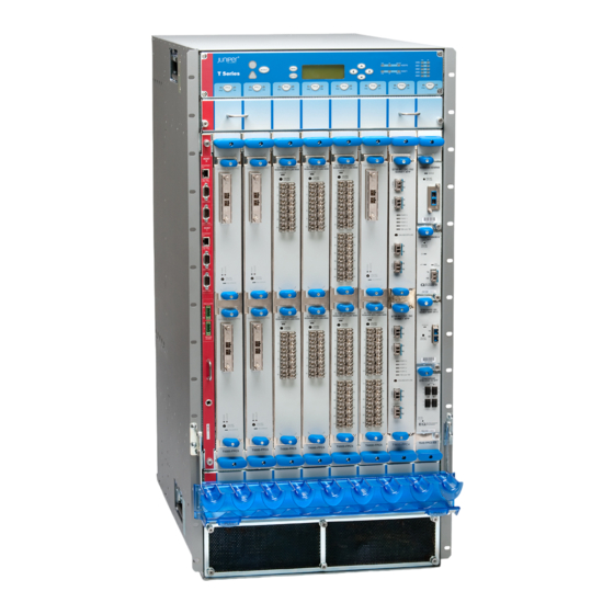
Page 34: Figure 1: Front View Of The T4000 Router
T4000 Core Router Hardware Guide Figure 1: Front View of the T4000 Router Front-mounting flange Center-mounting bracket Craft interface Fan tray T Se ries FPCs FANTR AY-T40 00 ESD point Air filter FA NT RA Y-T 40 00 Fan tray Air intake Copyright ©... -
Page 35: T4000 Hardware Component Overview
ESD point Grounding points Related T4000 Chassis Description on page 11 Documentation Overview of Installing the T4000 Router on page 119 T4000 Hardware Component Overview The T4000 Core Router supports the components in Table 3 on page 5, listed in alphabetic order. - Page 36 T4000 Core Router Hardware Guide Table 3: T4000 Hardware Components (continued) Component Hardware Model Number CLI Name Description Chassis “T4000 Chassis Description” on page 11 Cooling system, including fan trays and air filters “T4000 Cooling System Description” on page 25...
-
Page 37: T4000 Component Redundancy
T4000 Component Redundancy on page 7 T4000 Component Redundancy The T4000 Core Router is designed so that no single point of failure can cause the entire system to fail. The following major hardware components are redundant: Switch Interface Boards (SIBs)—The router has five SIBs. For more information, see “T4000 Switch Interface Board (SIB) Description”... - Page 38 T4000 Core Router Hardware Guide Related T4000 Router Description on page 3 Documentation Copyright © 2018, Juniper Networks, Inc.
-
Page 39: T4000 Router Release Notes
Errata with the T4000 Router Documentation on page 9 Outstanding Issues with the T4000 Router This topic lists outstanding hardware issues with the T4000 Core Router. To support the 10-Gigabit Ethernet LAN/WAN PIC with Oversubscription and SFP+ (model number PD-5-10XGE-SFPP) in the T1600-FPC4-ES (part number 710-013037), REV 13 and later is required. - Page 40 T4000 Core Router Hardware Guide Copyright © 2018, Juniper Networks, Inc.
-
Page 41: Chassis Components And Description
T4000 SONET Clock Generators (SCGs) Description on page 20 T4000 SONET Clock Generators (SCGs) LEDs on page 22 T4000 Chassis Description The T4000 Core Router chassis is a rigid sheet metal structure that houses all the other router components (see Figure 3 on page 12 Figure 4 on page 13). -
Page 42: Figure 3: Front View Of Router Chassis
T4000 Core Router Hardware Guide WARNING: The router must be connected to earth ground during normal operation. Figure 3: Front View of Router Chassis Front-mounting flange Center-mounting bracket Craft interface Fan tray T Se ries FPCs FANTR AY-T40 00 ESD point... -
Page 43: T4000 Cable Management System
Related T4000 Router Description on page 3 Documentation T4000 Router Physical Specifications on page 91 T4000 Component Serial Number Locations on page 379 T4000 Cable Management System The front cable management system (see Figure 5 on page 14) consists of a row of nine semicircular plastic bobbins mounted on the front of the router below the FPC card cage. -
Page 44: T4000 Connector Interface Panel (Cip) Description
This allows you to access the lower fan tray and the front air filter. Figure 5: Front Cable Management System For T4000 routers connected to a TX Matrix Plus router, you can use the optional rear cable management system (model number CBL-MGR-TXP-3D-LCC) to organize, support, and provide strain relief for the cables connected to the TXP-LCC-3D SIBs and the cables connected to the LCC-CBs. -
Page 45: Management Ports
15) that you use to connect the Routing Engines to external management devices. The upper set of ports, labeled , connects to the Routing Engine in slot ; and the lower set, labeled HOST 0 Copyright © 2018, Juniper Networks, Inc. -
Page 46: T4000 Alarm Relay Contacts
The craft interface allows you to view status and troubleshooting information at a glance and to perform many system control functions. It is hot-insertable and hot-removable. The craft interface is located on the front of the T4000 Core Router above the FPCs (see Figure 7 on page 17). -
Page 47: Craft Interface Front Panel
A four-line LCD is located in the craft interface, along with six navigation buttons. The LCD operates in two modes: LED idle mode LED alarm mode During normal operation, the LCD operates in idle mode and reports current status information, as shown in Figure 8 on page Copyright © 2018, Juniper Networks, Inc. -
Page 48: T4000 Midplane Description
Related T4000 Craft Interface LEDs Documentation T4000 Alarm Messages Overview on page 347 T4000 Midplane Description The midplane is located in the center of the chassis and forms the rear of the FPC card cage (see Figure 10 on page 19). -
Page 49: Figure 10: Midplane
Signal path—The midplane provides the signal path to the FPCs, SIBs, Routing Engines, CB, and other system components for monitoring and control of the system. Figure 10: Midplane Midplane FPC card cage Copyright © 2018, Juniper Networks, Inc. -
Page 50: T4000 Sonet Clock Generators (Scgs) Description
Taking the master SCG offline might result in a brief loss of SONET clock lock while the backup SCG becomes the master. Supported SCGs The T4000 router supports the SCG in Table 4 on page NOTE: Redundant SCGs must be the same model number, except during upgrade. -
Page 51: Scg Components
For information about configuring an interface transmit clock, see the Junos OS Network Interfaces Library for Routing Devices. Three LEDs— , and , located on the SCG faceplate, that display the FAIL MASTER status of the SCG. Copyright © 2018, Juniper Networks, Inc. -
Page 52: T4000 Sonet Clock Generators (Scgs) Leds
T4000 Core Router Hardware Guide Related T4000 SONET Clock Generators (SCGs) LEDs on page 22 Documentation Connecting the T4000 Router to an External Clocking Device Maintaining the T4000 SCGs on page 333 Troubleshooting the T4000 SCGs on page 349 T4000 SONET Clock Generators (SCGs) LEDs Three LEDs, located on the SCG faceplate, display the status of the SCG. - Page 53 Link is online and active. LINK No link. Related T4000 SONET Clock Generators (SCGs) Description on page 20 Documentation Connecting the T4000 Router to an External Clocking Device Maintaining the T4000 SCGs on page 333 Troubleshooting the T4000 SCGs on page 349...
- Page 54 T4000 Core Router Hardware Guide Copyright © 2018, Juniper Networks, Inc.
-
Page 55: Cooling System Components And Descriptions
CHAPTER 4 Cooling System Components and Descriptions T4000 Cooling System Description on page 25 T4000 Cooling System Description The cooling system components work together to keep all router components within the acceptable temperature range. The host subsystem monitors the temperature of the router components. -
Page 56: Fan Trays
To maintain proper cooling, do not operate the routing node with the rear fan tray removed for more than one minute. The T4000 router supports the fan trays listed in Table 6 on page Table 6: T4000 Supported Fan Trays... -
Page 57: Air Filters
Each DC power supply contains two blowers that cool that power supply. Related T4000 Router Description on page 3 Documentation Maintaining the T4000 Fan Trays on page 335 Troubleshooting the T4000 Cooling System on page 351 T4000 Router Environmental Specifications on page 88 Copyright © 2018, Juniper Networks, Inc. - Page 58 T4000 Core Router Hardware Guide Copyright © 2018, Juniper Networks, Inc.
-
Page 59: Host Subsystem Components And Descriptions
T4000 Host Subsystem Description on page 29 T4000 Control Board Description on page 30 T4000 LCC-CB on page 30 T4000 LCC-CB Control Board LEDs on page 31 T4000 Routing Engine Description on page 33 T4000 RE-C1800 Routing Engine Description on page 34... -
Page 60: T4000 Control Board Description
T4000 LCC-CB Control Board LEDs on page 31 T4000 Control Board Description The T4000 chassis supports up to two control boards. The Routing Engine requires an adjacent control board to provide control and monitoring functions for the router. These functions include determining Routing Engine mastership, controlling power and reset for the other router components, monitoring and controlling fan speed, and monitoring system status. -
Page 61: T4000 Lcc-Cb Control Board Leds
T4000 Control Board Description on page 30 Documentation T4000 Craft Interface LEDs T4000 LCC-CB Control Board LEDs on page 31 T4000 LCC-CB Control Board LEDs Status LEDs and port LEDs are located on the faceplate of the LCC-CB (see Figure 16 on page 32). -
Page 62: Lcc-Cb Leds
, the port labeled , and the LEDs for each port labeled are not currently supported. LINK Related T4000 Host Subsystem Description on page 29 Documentation T4000 Control Board Description on page 30 T4000 Craft Interface LEDs Copyright © 2018, Juniper Networks, Inc. -
Page 63: T4000 Routing Engine Description
The ports for connecting the Routing Engine to external management devices are located on the Connector Interface Panel (CIP). The T4000 router supports the Routing Engine in Table 9 on page Table 9: T4000 Supported Routing Engines First Supported... -
Page 64: T4000 Re-C1800 Routing Engine Description
T4000 Core Router Hardware Guide T4000 Connector Interface Panel (CIP) Description on page 14 T4000 RE-C1800 Routing Engine Description RE-C1800 Routing Engine Components on page 34 RE-C1800 Boot Order on page 35 RE-C1800 Routing Engine Components Each RE-C1800 Routing Engine... -
Page 65: Re-C1800 Boot Order
The RE-C1800 Routing Engine boots from the storage media in this order: the USB device, then the CompactFlash card (if present), then DISK1 , then the LAN. Related T4000 Host Subsystem Description on page 29 Documentation T4000 Routing Engine Description on page 33 T4000 Control Board Description on page 30 T4000 Craft Interface LEDs... -
Page 66: Routing Engine Specifications
Related T4000 Host Subsystem Description on page 29 Documentation T4000 Routing Engine Description on page 33 T4000 RE-C1800 Routing Engine Description on page 34 T4000 Craft Interface LEDs Routing Engine Specifications Table 11 on page 37 lists the current specifications for Routing Engines supported on M Series, MX Series, and T Series routers. -
Page 67: Table 11: Routing Engine Specifications
T1600 router: 11.4R2 64-bit Junos OS on a T1600 router in a routing matrix: 11.4R2 RE-C2600 2.6-GHz 16 GB Gigabit 4 GB TX Matrix Plus – Ethernet CompactFlash router: 9.6R2 card Copyright © 2018, Juniper Networks, Inc. - Page 68 T4000 Core Router Hardware Guide Table 11: Routing Engine Specifications (continued) Routing Connection First Junos OS Switch Control Engine Processor Memory to PFEs Disk Media Support Board RE-A-1800x2 1800-MHz 8 GB or 16 Gigabit 32 GB SSD 4 GB 10.4 –...
-
Page 69: Table 12: End-Of-Life Routing Engine Specifications
RE-850-1536 850-MHz 1536 MB Fast 40 GB hard 1 GB PSN-2011-04-226 Pentium III Ethernet disk CompactFlash card RE-M40 200-MHz 256 MB Fast 6.4 GB hard 80 MB FA-HW-0101-001 Pentium Ethernet disk CompactFlash card Copyright © 2018, Juniper Networks, Inc. -
Page 70: Supported Routing Engines By Router
T4000 Core Router Hardware Guide Table 12: End-of-Life Routing Engine Specifications (continued) Routing Connection First Junos OS Engine Processor Memory to PFEs Disk Media Support EOL Details RE-M40-333-7 68 333-MHz 768 MB Fast 10 GB hard 80 MB PSN-2003-01-063 Pentium II... -
Page 71: M7I Routing Engines
T320 Routing Engines on page 51 T640 Routing Engines on page 51 T1600 Routing Engines on page 52 T4000 Routing Engines on page 53 TX Matrix Routing Engines on page 54 TX Matrix Plus Routing Engines on page 54 TX Matrix Plus (with 3D SIBs) Routing Engines on page 54... -
Page 72: M40E Routing Engines
T4000 Core Router Hardware Guide Table 14: M10i Routing Engines (continued) First Supported Name in CLI 32-bit Junos OS Management Internal Ethernet Model Number Output Release Ethernet Interface Interface RE-850-1536 (EOL details: RE-850 fxp0 fxp1 TSB15553 fxp2 RE-B-1800X1-4G 11.4R4 fxp0 RE-B-1800x1 12.1R2... -
Page 73: M320 Routing Engines
12.1R3 bcm0 RE-A-1800X4-8G 11.4R5 10.4 fxp0 RE-A-1800X4 12.1R3 12.2 MX5, MX10, MX40, and MX80 Routing Engine Table 18 on page 44 lists the Routing Engines supported by the MX5, MX10, MX40, and MX80 routers. Copyright © 2018, Juniper Networks, Inc. -
Page 74: Mx104 Routing Engines
T4000 Core Router Hardware Guide Table 18: MX5, MX10, MX40, and MX80 Routing Engine First Supported First Supported Management Model Name in CLI 32-bit Junos OS 64-bit Junos OS Ethernet Number Output Release Release Interface Internal Ethernet Interface Built-in Routing Routing Engine 12.3... -
Page 75: Mx480 Routing Engines
RE-S-1300 (EOL details: fxp2 TSB16556 RE-S-2000-4096 RE-S-2000 – fxp0 fxp1 (EOL details: fxp2 TSB16735 RE-S-1800X2-8G 11.4R5 10.4 fxp0 RE-S-1800x2 (EOL details: 12.1R3 TSB16556 RE-S-1800X2-16G 11.4R5 10.4 fxp0 RE-S-1800x2 (EOL details: 12.1R3 TSB16556 Copyright © 2018, Juniper Networks, Inc. -
Page 76: Mx960 Routing Engines
T4000 Core Router Hardware Guide Table 21: MX480 Supported Routing Engines (continued) First Supported First Supported Management Name in CLI 32-bit Junos OS 64-bit Junos OS Ethernet Internal Ethernet Model Number Output Release Release Interface Interface RE-S-1800X4-8G RE-S-1800X4 11.4R5 10.4 fxp0 12.1R3... -
Page 77: Mx2008 Routing Engines
Output OS Release Interface Interface REMX2008-X8-64G 15.1F7 fxp0 ixlv0 RE-MX2008-X8-64G ixlv1 REMX2008-X8-64G-LT 17.2R1 fxp0 ixlv0 REMX2008-X8-64G-L T ixlv1 MX2010 Routing Engines Table 24 on page 48 lists the Routing Engines supported by MX2010 routers. Copyright © 2018, Juniper Networks, Inc. -
Page 78: Mx2020 Supported Routing Engines
T4000 Core Router Hardware Guide Table 24: MX2010 Supported Routing Engines Management Name in CLI First Supported 64-bit Junos Ethernet Internal Ethernet Model Number Output OS Release Interface Interface RE-MX2000-1800X4 RE-S-1800x4 12.3R2 fxp0 REMX2K-1800-32G-S 12.3R4 fxp0 RE-S-1800x4 13.2R1 REMX2K-X8-64G 15.1F5-S1... -
Page 79: Mx10003 Routing Engines
The PTX3000 supports 64-bit Junos OS only. Table 28: PTX3000 Routing Engines Name in CLI First Supported Junos OS Management Internal Ethernet Model Number Output Release Ethernet Interface Interface RE-DUO-C2600-16G 13.2R2 ixgbe0 RE-DUO-2600 ixgbe1 Copyright © 2018, Juniper Networks, Inc. -
Page 80: Ptx5000 Routing Engines
T4000 Core Router Hardware Guide Table 28: PTX3000 Routing Engines (continued) Name in CLI First Supported Junos OS Management Internal Ethernet Model Number Output Release Ethernet Interface Interface RCB-PTX-X6-32G RE-PTX-2X00x6 16.1R4 ixlv0 17.1R1 ixlv1 This Routing Engine does not support Junos OS Release 16.2. -
Page 81: Ptx10008 And Ptx10016 Routing Engines
Internal Name in CLI First Supported 32-bit First Supported 64-bit Ethernet Ethernet Model Number Output Junos OS Release Junos OS Release Interface Interface RE-600-2048 (EOL – fxp0 fxp1 RE-3.0 TSB14373 details: RE-3.0 fxp2 (RE-600) Copyright © 2018, Juniper Networks, Inc. -
Page 82: T1600 Routing Engines
T4000 Core Router Hardware Guide Table 32: T640 Routing Engines (continued) Management Internal Name in CLI First Supported 32-bit First Supported 64-bit Ethernet Ethernet Model Number Output Junos OS Release Junos OS Release Interface Interface RE-1600-2048 (EOL RE-4.0 – fxp0... -
Page 83: T4000 Routing Engines
T1600 router in a 11.4R2 routing matrix: 11.4R2 T4000 Routing Engines Table 34 on page 53 lists the Routing Engines supported by the T4000 router. NOTE: The T4000 router supports 64-bit Junos OS only. Table 34: T4000 Routing Engines Management... -
Page 84: Tx Matrix Routing Engines
T4000 Core Router Hardware Guide TX Matrix Routing Engines Table 35 on page 54 lists the Routing Engines supported by the TX Matrix router. Table 35: TX Matrix Routing Engines First First Supported Supported Management Internal Name in CLI 32-bit Junos... -
Page 85: Table 37: Routing Engines On Tx Matrix Plus With 3D Sibs
Ethernet Ethernet Model Number Output Release Release Interface Interface RE-DUO-C2600-16G RE-TXP-SFC 64-bit Junos OS: 11.4 ixgbe0 RE-DUO-2600 ixgbe1 Related Routing Engine Specifications on page 36 Documentation Understanding Internal Ethernet Interfaces Understanding Management Ethernet Interfaces Copyright © 2018, Juniper Networks, Inc. - Page 86 T4000 Core Router Hardware Guide Copyright © 2018, Juniper Networks, Inc.
-
Page 87: Line Card Components And Descriptions
FPCs house the PICs that connect the T4000 Core Router to network media. The main function of an FPC is to connect the PICs installed in it to the other T4000 router components. The Packet Forwarding Engine receives incoming packets from the PICs installed on the FPC and forwards them through the switch planes to the appropriate destination port. -
Page 88: T4000 Fpc Components
T Series Internet Processor ASICs, and a Memory Mezzanine Board (MMB) which includes the Queuing and Memory Interface ASICs. Each T4000-FPC5-3D or T4000-FPC5-LSR has two Packet Forwarding Engines. Each Packet Forwarding Engine consists of a Packet Processing ASIC, Interface ASIC, and Switch Interface ASIC. -
Page 89: Figure 19: Enhanced Scaling T1600-Fpc4
Chapter 6: Line Card Components and Descriptions The enhanced scaling T1600-FPC4 is shown in Figure 19 on page Figure 19: Enhanced Scaling T1600-FPC4 Copyright © 2018, Juniper Networks, Inc. -
Page 90: Fpc Terminology
T4000 Core Router Hardware Guide The T4000 FPC5 (T4000-FPC5-3D and T4000-FPC5-LSR) is shown in Figure 20 on page Figure 20: FPC5 Supported by the Router FPC Terminology Regardless of whether you are holding an FPC vertically or horizontally, this document... -
Page 91: T4000 Fpcs Supported
Table 39 on page 61. You can install any combination of the following FPCs. The First Junos OS Release Supported column indicates the first release that the FPC is supported in the T4000 router. Table 39: FPCs Supported by the T4000 Router Maximum... -
Page 92: T4000 Pic Description
T4000 Core Router Hardware Guide Table 39: FPCs Supported by the T4000 Router (continued) Maximum First Junos OS FPC Model Maximum Throughput per Release Type FPC Name Number CLI Name Number of PICs Supported Enhanced T640-FPC4-1P-ES FPC Type 4.1-ES 100 Gbps 12.1R2... -
Page 93: T4000 Pics Supported
Services PICs on page 66 SONET/SDH PICs on page 66 ATM IQ PICs Table 41 on page 63 lists the ATM IQ PICs supported by the T4000 router. Table 41: ATM IQ PICs Supported in the T4000 Router First Junos OS Release... -
Page 94: Gigabit Ethernet Pics
Enhanced IQ (IQE) PIC with SFP (T4000 Router) Gigabit Ethernet PICs Table 43 on page 64 lists the Gigabit Ethernet PICs supported by the T4000 router. Table 43: Gigabit Ethernet PICs Supported in the T4000 Router First Junos OS Release... -
Page 95: 40-Gigabit Ethernet Pics
Chapter 6: Line Card Components and Descriptions Table 44: 10-Gigabit Ethernet PICs Supported in the T4000 Router First Junos OS Release PIC Family and Type Ports Model Number Connectors Support 10-Gigabit Ethernet PIC with PC-1XGE-XENPAK Optical: SC 12.2R2 XENPAK (T4000 Router) -
Page 96: Services Pics
T4000 Core Router Hardware Guide Table 46: 100-Gigabit Ethernet PICs Supported in the T4000 Router First Junos OS Release PIC Family and Type Ports Model Number Connectors Support 100-Gigabit Ethernet PIC with PF-1CGE-CFP Optical: SC, LC, or 12.1 CFP (T4000 Router) -
Page 97: T4000 End-Of-Life Pics Supported
T4000 PIC/FPC Compatibility on page 68 T4000 End-of-Life PICs Supported Table 49 on page 67 lists the end-of-life PICs supported by the T4000 router. The PICs are listed alphabetically by PIC family. NOTE: End-of-life (EOL) indicates that the product has been removed from the price list and is no longer available for purchase. -
Page 98: T4000 Pic/Fpc Compatibility
T4000 PIC/FPC Compatibility on page 68 T4000 PIC/FPC Compatibility The PIC/FPC compatibility matrixes list the current PICs for the T4000 router. For example, Junos OS Release 12.1 is the first release in which the T1600-FPC4-ES supports the OC192/STM64, 4-port PIC in the T4000 router. -
Page 99: Table 50: T4000 Pic/Fpc Compatibility Type 1
Chapter 6: Line Card Components and Descriptions Table 50: T4000 PIC/FPC Compatibility Type 1 (continued) Type 1 PIC PIC Model Number T640-FPC1-ES Channelized OC3 IQ PIC (T4000 PB-1CHOC3-SMIR-QPP 12.1.R2 Router) Channelized STM1 IQ PIC (T4000 PB-1CHSTM1-SMIR-QPP 12.1.R2 Router) Channelized IQE PICs... -
Page 100: Pic/Fpc Compatibility (Type 2)
T4000 Core Router Hardware Guide Table 50: T4000 PIC/FPC Compatibility Type 1 (continued) Type 1 PIC PIC Model Number T640-FPC1-ES SONET/SDH OC3/STM1 PB-4OC3-1OC12-SON-SFP 12.1.R2 (Multi-Rate) PICs with SFP (T4000 Router) SONET/SDH OC12/STM4 PB-1OC12-SON-SFP 12.1.R2 (Multi-Rate) PICs with SFP (T4000 Router) -
Page 101: Pic/Fpc Compatibility (Type 3)
Chapter 6: Line Card Components and Descriptions Table 51: T4000 PIC/FPC Compatibility Type 2 (continued) Type 2 PIC PIC Model Number T640-FPC2-ES SONET/SDH OC3/STM1 PB-4OC3-1OC12-SON2-SFP 12.2R2 (Multi-Rate) PICs with SFP (T4000 Router) SONET/SDH OC12c/STM4 EOL PIC PB-4OC12-SON-MM 12.2R2 (T4000 Router) -
Page 102: Table 52: T4000 Pic/Fpc Compatibility Type 3
T4000 Core Router Hardware Guide Table 52: T4000 PIC/FPC Compatibility Type 3 (continued) Type 3 PIC PIC Model Number T640-FPC3-ES 10-Gigabit Ethernet PICs 10-Gigabit Ethernet PIC with PC-1XGE-XENPAK 12.2R2 XENPAK (T4000 Router) 10-Gigabit Ethernet DWDM OTN PC-1XGE-DWDM-OTN 12.1R2 EOL PIC (T4000 Router) -
Page 103: Pic/Fpc Compatibility (Type 4)
PIC/FPC Compatibility (Type 4) Table 53 on page 73 provides a PIC/FPC compatibility matrix for the current Type 4 PICs for the T4000 router and Type 4 FPCs. Table 53: T4000 PIC/FPC Compatibility Type 4 Type 4 PIC PIC Model Number... -
Page 104: Table 54: T4000 Pic/Fpc Compatibility Type 5
T4000 Core Router Hardware Guide Table 54: T4000 PIC/FPC Compatibility Type 5 (continued) Type 5 PIC PIC Model Number T4000-FPC5-3D T4000-FPC5-LSR 10-Gigabit Ethernet LAN/WAN PIC PF-12XGE-SFPP 12.1 12.3R2 with SFP+ (T4000 Router) 10-Gigabit Ethernet LAN/WAN PIC PF-24XGE-SFPP 12.2 12.3R2 with Oversubscription and SFP+... -
Page 105: Power System Components And Descriptions
Supported Power Supplies on page 75 Power Supply Components on page 76 Redundancy on page 76 Power Supply Slots The T4000 router has two redundant, load-sharing power supplies, located at the lower rear of the chassis in slots (top to bottom). Power supplies are PEM0 PEM1 hot-removable and hot-insertable. -
Page 106: Power Supply Components
Redundancy When the T4000 router is operating normally and both power supplies are switched on, load sharing between them occurs automatically. When one power supply fails or is turned off, the other power supply immediately assumes the entire electrical load for the system. -
Page 107: T4000 Six-Input Dc Power Supply Leds
Chapter 7: Power System Components and Descriptions Related T4000 Six-Input DC Power Supply LEDs on page 77 Documentation Maintaining the T4000 Power System on page 338 Troubleshooting the T4000 Power System on page 363 T4000 Six-Input DC Power Supply LEDs... - Page 108 T4000 Core Router Hardware Guide Copyright © 2018, Juniper Networks, Inc.
-
Page 109: Switch Fabric Components And Descriptions
T4000 SIB LEDs on page 81 T4000 Switch Interface Board (SIB) Description SIBs create the switch fabric for the T4000 Core Router. Each T4000 router contains five SIBs, located at the center rear of the chassis in the slots labeled... -
Page 110: T4000-Sib Description
Figure 24 on page 80 shows a TXP-LCC-3D SIB (model number SIB-TXP-3D-LCC) that is required to connect a T4000 line card chassis (LCC) to TXP-F13-3D SIBs in a TX Matrix Plus router. See TX Matrix Plus Router Hardware Guide. Figure 24: TXP-LCC-3D SIB... -
Page 111: T4000 Sib Leds
TXP-LCC-3D SIB. The FAIL LEDs are replicated on the craft interface. Related T4000 Switch Interface Board (SIB) Description on page 79 Documentation T4000 SIB LEDs on page 81 Maintaining the T4000 SIBs on page 339 Replacing a T4000-SIB on page 319... -
Page 112: Figure 25: Txp-3D-Lcc Sib Leds
T4000 Core Router Hardware Guide Figure 25: TXP-3D-LCC SIB LEDs FAIL ACTIVE ONLINE/ OFFLINE FAIL ACTIVE Table 60: TXP-LCC-3D SIB Port LEDs Label Color State Description Green On steadily The link between the TXP-F13-3D SIB port and the TXP-LCC-3D SIB port has LINK been established successfully. - Page 113 Chapter 8: Switch Fabric Components and Descriptions Related T4000 Switch Interface Board (SIB) Description on page 79 Documentation T4000 TXP-LCC-3D SIB Description on page 80 Copyright © 2018, Juniper Networks, Inc.
- Page 114 T4000 Core Router Hardware Guide Copyright © 2018, Juniper Networks, Inc.
-
Page 115: Site Planning, Preparation, And Specifications
Planning and Preparing the Site on page 87 Calculating System Power Requirements on page 97 DC Power Specifications A on page 101 Network Cable and Transceiver Planning on page 109 Management Cable and Transceiver Specifications and Pinouts on page 113 Copyright © 2018, Juniper Networks, Inc. - Page 116 T4000 Core Router Hardware Guide Copyright © 2018, Juniper Networks, Inc.
-
Page 117: Planning And Preparing The Site
CHAPTER 9 Planning and Preparing the Site Overview of Preparing the Site for the T4000 Router on page 87 T4000 Router Environmental Specifications on page 88 General Site Guidelines on page 89 T4000 Chassis Grounding Cable and Lug Specifications on page 90... -
Page 118: T4000 Router Environmental Specifications
Verify that the plan for power installation meets all electrical safety guidelines. See: General Electrical Safety Guidelines and Warnings on page 421 T4000 DC Power Electrical Safety Guidelines on page 424 Verify that your rack meets the minimum requirements for the installation of the router. -
Page 119: General Site Guidelines
Articles 110-16, 110-17, and 110-18 of the National Electrical Code, ANSI/NFPA 70. Related Routine Maintenance Procedures for the T4000 Router on page 331 Documentation General Safety Guidelines and Warnings on page 393 Qualified Personnel Warning on page 396... -
Page 120: T4000 Chassis Grounding Cable And Lug Specifications
DC power cables.) Figure 26: Grounding Cable Lug Related Tools and Parts Required to Ground the T4000 Router on page 173 Documentation Connecting the T4000 Grounding Cable on page 174 Copyright © 2018, Juniper Networks, Inc. -
Page 121: T4000 Clearance Requirements For Airflow And Hardware Maintenance
Related T4000 Cooling System Description on page 25 Documentation Rack Requirements for the T4000 Router on page 93 T4000 Router Physical Specifications on page 91 T4000 Router Physical Specifications Table 63 on page 92 lists the router's physical specifications. -
Page 122: Table 63: Physical Specifications
T4000 Core Router Hardware Guide Table 63: Physical Specifications Description Value Chassis dimensions 37.45 in. (95.1 cm) high 17.43 in. (44.3 cm) wide 31 in. (78.7 cm) deep Total depth (including front cable management system) 35.5 in. (90.2 cm) 11.5 in. (29.2 cm) from front of chassis to center-mounting... -
Page 123: Site Electrical Wiring Guidelines
Related T4000 Router Description on page 3 Documentation T4000 Chassis Description on page 11 T4000 Installation Safety Guidelines on page 120 Site Electrical Wiring Guidelines Table 64 on page 93 describes the factors you must consider while planning the electrical wiring at your site. - Page 124 T4000 Core Router Hardware Guide For open-frame racks, center-mounting is preferable to front-mounting because the more even distribution of weight provides greater stability. The router is designed for installation in a 19-in. rack as defined in Cabinets, Racks, Panels, and Associated Equipment (document number EIA-310-D) published by the Electronics Components Industry Association ( http://www.ecianow.org/...
-
Page 125: Figure 28: Typical Open-Frame Rack
For maximum stability, also secure the rack to ceiling brackets. Related T4000 Router Physical Specifications on page 91 Documentation T4000 Clearance Requirements for Airflow and Hardware Maintenance on page 91 Copyright © 2018, Juniper Networks, Inc. - Page 126 T4000 Core Router Hardware Guide Copyright © 2018, Juniper Networks, Inc.
-
Page 127: Calculating System Power Requirements
Requirement (Amps @ Component –48 VDC) Base system, not including FPCs and PICs (includes five SIB-I-T4000 SIBs, 30.8 A one host subsystem, one SCG, cooling system at normal speed, and craft interface) and two power supplies Base system, not including FPCs and PICs (includes five TXP-LCC-3D SIBs, 31.0 A... - Page 128 T4000 Core Router Hardware Guide Table 65: Typical DC Power Requirements for T4000 Components (continued) Current Requirement (Amps @ Component –48 VDC) C1800 Routing Engine 1.7 A 0.2 A Redundant backup six-input DC power supply 5.2 A Cooling system with FAN-REAR-TXP-LCC (normal speed) 8.2 A...
- Page 129 Related T4000 DC Power System Electrical Specifications on page 101 Documentation Overview of Preparing the Site for the T4000 Router on page 87 T4000 DC Power Distribution on page 104 T4000 Power System Description on page 75 Copyright © 2018, Juniper Networks, Inc.
- Page 130 T4000 Core Router Hardware Guide Copyright © 2018, Juniper Networks, Inc.
-
Page 131: Dc Power Specifications A
T4000 DC Power System Electrical Specifications on page 101 T4000 DC Power Supply Specifications on page 102 T4000 Power Management (Four 60-A Cables on a Six-Input DC Power Supply) on page 103 T4000 Power Management (Three 80-A Cables on a Six-Input DC Power... -
Page 132: T4000 Dc Power Supply Specifications
Documentation T4000 DC Power Supply Specifications on page 102 T4000 DC Power Requirements on page 97 T4000 DC Power Cable and Lugs Specifications on page 105 T4000 DC Power Distribution on page 104 T4000 DC Power Supply Specifications Table 67 on page 102 lists the DC power supply electrical specifications. -
Page 133: T4000 Power Management
FRU states might change from Online to Offline or Present, or the interfaces might flap, or some traffic might drop. Related Connecting DC Power to the T4000 Router (Four 60-A Inputs) on page 194 Documentation Configuring DC Power on a T4000 Router on page 213... -
Page 134: T4000 Power Management
Online to Offline or Present, or the interfaces might flap, or some traffic might drop. Related Connecting DC Power to the T4000 Router (Three 80-A DC Power Cables to Six 60-A Documentation Inputs) on page 198 Configuring DC Power on a T4000 Router on page 213... -
Page 135: T4000 Dc Power Cable And Lugs Specifications
Connecting DC Power to the T4000 Router (Five 60-A Inputs) on page 190 Connecting DC Power to the T4000 Router (Four 60-A Inputs) on page 194 Connecting DC Power to the T4000 Router (Three 80-A DC Power Cables to Six 60-A Inputs) on page 198... -
Page 136: Dc Power Lugs
Before router installation begins, a licensed electrician must attach a cable lug to the power cables that you supply. A cable with an incorrectly attached lug can damage the router. Related T4000 Power System Description on page 75 Documentation Copyright © 2018, Juniper Networks, Inc. - Page 137 Connecting DC Power to the T4000 Router (Five 60-A Inputs) on page 190 Connecting DC Power to the T4000 Router (Four 60-A Inputs) on page 194 Connecting DC Power to the T4000 Router (Three 80-A DC Power Cables to Six 60-A Inputs) on page 198...
- Page 138 T4000 Core Router Hardware Guide Copyright © 2018, Juniper Networks, Inc.
-
Page 139: Network Cable And Transceiver Planning
Attenuation is caused by passive media components, such as cables, cable splices, and connectors. Although attenuation is significantly lower for optical fiber than for other media, it still occurs in both multimode Copyright © 2018, Juniper Networks, Inc. -
Page 140: Calculating Power Budget And Power Margin For Fiber-Optic Cables
You can use the to find information about Hardware Compatibility Tool the pluggable transceivers supported on your Juniper Networks device. To calculate the power budget and power margin, perform the following tasks: Calculating Power Budget for Fiber-Optic Cable on page 110... -
Page 141: Calculating Power Margin For Fiber-Optic Cable
(0.5 dB per connector, or 2.5 dB) and two splices (0.5 dB per splice, or 1 dB) as well as higher-order mode losses (0.5 dB). The power margin (P ) is calculated as follows: Copyright © 2018, Juniper Networks, Inc. - Page 142 T4000 Core Router Hardware Guide – LL = 13 dB – 2 km (1 dB/km) – 5 (0.5 dB) – 2 (0.5 dB) – 0.5 dB = 13 dB – 2 dB – 2.5 dB – 1 dB – 0.5 dB...
-
Page 143: Management Cable And Transceiver Specifications And Pinouts
Documentation Connecting the T4000 Router to a Management Ethernet Device on page 180 Connecting the T4000 Router to a Management Console or Auxiliary Device on page 178 DB-9 Connector Pinouts for the Routing Engine AUXILIARY and CONSOLE Ports on page 114 RJ-45 Connector Pinouts for the T4000 Management ETHERNET Port on page 115 Copyright ©... -
Page 144: T4000 Alarm Relay Contact Wire Specifications
Related T4000 Connector Interface Panel (CIP) Description on page 14 Documentation T4000 Routing Engine Interface Cable Specifications on page 113 Connecting the T4000 Router to a Management Console or Auxiliary Device on page 178 Copyright © 2018, Juniper Networks, Inc. -
Page 145: Rj-45 Connector Pinouts For The T4000 Management Ethernet Port
Termination network Related T4000 Connector Interface Panel (CIP) Description on page 14 Documentation Connecting the T4000 Router to a Management Ethernet Device on page 180 T4000 Routing Engine Interface Cable Specifications on page 113 Copyright © 2018, Juniper Networks, Inc. - Page 146 T4000 Core Router Hardware Guide Copyright © 2018, Juniper Networks, Inc.
-
Page 147: Initial Installation And Configuration
Connecting the Router to Power on page 185 Powering On the Router on page 207 Configuring the JUNOS Software on page 209 Upgrading to a T4000 Router From a T640 or T1600 Router on page 217 Copyright © 2018, Juniper Networks, Inc. - Page 148 T4000 Core Router Hardware Guide Copyright © 2018, Juniper Networks, Inc.
-
Page 149: Installation Overview
“Installing the T4000 Mounting Hardware for an Open-Frame Rack” on page 133. Install the router into the rack. See: Overview of Installing the T4000 Router into a Rack on page 137 Overview of Installing a T4000 Router Using a Mechanical Lift on page 139 Copyright © 2018, Juniper Networks, Inc. -
Page 150: T4000 Installation Safety Guidelines
Connecting DC Power to the T4000 Router (Five 60-A Inputs) on page 190 Connecting DC Power to the T4000 Router (Four 60-A Inputs) on page 194 Connecting DC Power to the T4000 Router (Three 80-A DC Power Cables to Six 60-A Inputs) on page 198 Power on the router. -
Page 151: Chassis Lifting Guidelines
Keep your knees bent and your back relatively straight and avoid twisting your body as you lift. Balance the load evenly and be sure that your footing is solid. Related Overview of Preparing the Site for the T4000 Router on page 87 Documentation Copyright © 2018, Juniper Networks, Inc. - Page 152 T4000 Core Router Hardware Guide Copyright © 2018, Juniper Networks, Inc.
-
Page 153: Unpacking The Router
Unpacking the Router Overview of Unpacking the T4000 Router on page 123 Tools and Parts Required to Unpack the T4000 Router on page 123 Unpacking the T4000 Router on page 124 Verifying the T4000 Router Parts Received on page 125... -
Page 154: Unpacking The T4000 Router
T4000 Core Router Hardware Guide Unpacking the T4000 Router on page 124 Verifying the T4000 Router Parts Received on page 125 Unpacking the T4000 Router The router is shipped in a wooden crate. A wooden pallet forms the base of the crate. -
Page 155: Verifying The T4000 Router Parts Received
Related Overview of Unpacking the T4000 Router on page 123 Documentation Tools and Parts Required to Unpack the T4000 Router on page 123 Verifying the T4000 Router Parts Received on page 125 Verifying the T4000 Router Parts Received A packing list is included in each shipment. Check the parts in the shipment against the items on the packing list. -
Page 156: Table 73: Router Parts List
T4000 Core Router Hardware Guide The main shipment contains the router chassis with installed components, listed in Table 73 on page 126, and an accessory box, which contains the parts listed in Table 74 on page 127. Table 73: Router Parts List... -
Page 157: Table 74: Accessory Box Parts List
Bag of 14 Serial cable, 6-ft length, to connect Routing Engine to management console End User License Agreement Related Overview of Unpacking the T4000 Router on page 123 Documentation Unpacking the T4000 Router on page 124 Copyright © 2018, Juniper Networks, Inc. - Page 158 T4000 Core Router Hardware Guide Copyright © 2018, Juniper Networks, Inc.
-
Page 159: Installing The Mounting Hardware
CHAPTER 16 Installing the Mounting Hardware Installing the T4000 Mounting Hardware for a Four-Post Rack or Cabinet on page 129 Installing the T4000 Mounting Hardware for an Open-Frame Rack on page 133 Installing the T4000 Mounting Hardware for a Four-Post Rack or Cabinet... -
Page 160: Installing The Large Mounting Shelf
T4000 Core Router Hardware Guide Table 75: Four-Post or Cabinet Rack Mounting Hole Locations (continued) Large Spacer Small Hole Distance Above U Division Shelf Bars Shelf 13.76 in. (34.9 cm) 7.86 U 8.51 in. (21.6 cm) 4.86 U 6.76 in. (17.1 cm) 3.86 U... -
Page 161: Installing The Small Shelf
The bottom of the small shelf on the rear rack rails must align with the bottom of the large shelf on the front rack rails. Partially insert screws into the open holes in the flanges of the small shelf. Tighten all the screws completely. Copyright © 2018, Juniper Networks, Inc. -
Page 162: Installing The Spacer Bars
Tighten all the screws completely. Figure 33: Positioning the Spacer Bar on the Rack Related Rack Requirements for the T4000 Router on page 93 Documentation Installing the T4000 Mounting Hardware for an Open-Frame Rack on page 133 Copyright © 2018, Juniper Networks, Inc. -
Page 163: Installing The T4000 Mounting Hardware For An Open-Frame Rack
Chapter 16: Installing the Mounting Hardware Installing the T4000 Mounting Hardware for an Open-Frame Rack In an open-frame rack, center-mounting is generally preferable to front-mounting because the more even distribution of weight provides greater stability. If you center-mount the chassis, you use the center-mounting brackets attached to the chassis. If you front-mount the chassis, you use the front-mounting flanges, and must remove the center-mounting brackets. -
Page 164: Removing The Center-Mounting Brackets From The Chassis
T4000 Core Router Hardware Guide On the rear of each rack rail, partially insert a mounting screw into the lowest hole specified in Table 76 on page 133 for the large shelf. Install the large shelf on the rack. Rest the bottom slot of each flange on a mounting screw. -
Page 165: Removing The Spacer Bars
If you are installing the chassis in an open-frame rack, removing the spacer bars is optional. To remove the spacer bars: Remove the screws that fasten the spacer bar to the front-mounting flange Remove the spacer bars. Copyright © 2018, Juniper Networks, Inc. - Page 166 T4000 Core Router Hardware Guide Related Rack Requirements for the T4000 Router on page 93 Documentation Installing the T4000 Mounting Hardware for a Four-Post Rack or Cabinet on page 129 Copyright © 2018, Juniper Networks, Inc.
-
Page 167: Overview Of Installing The Router Into A Rack
Verify that the site has been prepared for the router installation. “Overview of Preparing the Site for the T4000 Router” on page Because of the T4000 router's size and weight—up to 663.6 lb (301.0 kg) fully configured—we strongly recommend that you lift the router into the rack using a mechanical lift. - Page 168 T4000 Core Router Hardware Guide Copyright © 2018, Juniper Networks, Inc.
-
Page 169: Installing The Router Into A Rack With A Mechanical Lift
Mechanical Lift Overview of Installing a T4000 Router Using a Mechanical Lift on page 139 Tools Required to Install the T4000 Router Using a Mechanical Lift on page 139 Installing the T4000 Router Using a Mechanical Lift on page 140... -
Page 170: Installing The T4000 Router Using A Mechanical Lift
Removing the T4000 Power Supplies on page 140 Attaching the T4000 Installation Handle on page 141 Installing the T4000 Chassis in a Rack or Cabinet Using a Mechanical Lift on page 141 Removing the T4000 Installation Handle on page 144... -
Page 171: Attaching The T4000 Installation Handle
141). Figure 37: Attaching the Installation Handle Installing the T4000 Chassis in a Rack or Cabinet Using a Mechanical Lift Because of the router's size and weight—up to 663.6 lb (301.0 kg) depending on configuration—we strongly recommend that you install the router using a lift. - Page 172 T4000 Core Router Hardware Guide To mount the chassis in the rack or cabinet using a lift (see Figure 38 on page 143): If you are installing the router in an open-frame rack, ensure that the rack is in its permanent location and is secured to the building.
-
Page 173: Figure 38: Lifting The Router
Chapter 18: Installing the Router into a Rack With a Mechanical Lift Figure 38: Lifting the Router Copyright © 2018, Juniper Networks, Inc. -
Page 174: Removing The T4000 Installation Handle
Figure 39: Installing the Router in a Four-Post Rack NOTE: For an illustration of the mounting hardware required for an open-frame rack, see “Installing the T4000 Mounting Hardware for an Open-Frame Rack” on page 133. Removing the T4000 Installation Handle... -
Page 175: Reinstalling The T4000 Power Supplies
Figure 40: Reinstalling the Power Supplies Related Overview of Installing a T4000 Router Using a Mechanical Lift on page 139 Documentation Tools Required to Install the T4000 Router Using a Mechanical Lift on page 139 Copyright © 2018, Juniper Networks, Inc. - Page 176 T4000 Core Router Hardware Guide Copyright © 2018, Juniper Networks, Inc.
-
Page 177: Installing The Router Into A Rack Without A Mechanical Lift
Mechanical Lift Overview of Installing a T4000 Router Without a Mechanical Lift on page 147 Tools Required to Install the T4000 Router Without a Mechanical Lift on page 148 Removing T4000 Components from the Chassis on page 148 Installing the T4000 Chassis in a Rack or Cabinet Manually on page 160... -
Page 178: Tools Required To Install The T4000 Router Without A Mechanical Lift
3/8-in. nut driver ESD grounding wrist strap Related Overview of Installing a T4000 Router Without a Mechanical Lift on page 147 Documentation Removing T4000 Components from the Chassis on page 148 Installing the T4000 Chassis in a Rack or Cabinet Manually on page 160... -
Page 179: Figure 41: Components To Remove From The Rear Of The T4000 Router
Chapter 19: Installing the Router into a Rack Without a Mechanical Lift Figure 41: Components to Remove from the Rear of the T4000 Router Fan tray SCGs Control board 0 Control board 1 SIBs Power supply 0 Power supply 1... -
Page 180: Figure 42: Components To Remove From The Front Of The T4000 Router
T4000 Core Router Hardware Guide Figure 42: Components to Remove from the Front of the T4000 Router Fan tray T Se ries FPCs FANTR AY-T40 00 FA NT RA Y-T 40 00 Fan tray Remove the components first from the rear of the chassis... -
Page 181: Removing The T4000 Dc Power Supplies
Chapter 19: Installing the Router into a Rack Without a Mechanical Lift Removing the T4000 DC Power Supplies The power supplies are located at the rear of the chassis below the SIBs. Each six-input DC power supply weighs approximately 39.7 lb (18.0 kg). -
Page 182: Removing The T4000 Sibs
T4000 Core Router Hardware Guide Removing the T4000 SIBs Five SIBs are installed in the router. The SIBs are located in the rear of the chassis in the slots marked SIB0 through SIB4 . Each SIB weighs approximately 7.1 lb (3.2 kg). -
Page 183: Removing The T4000 Control Boards
Chapter 19: Installing the Router into a Rack Without a Mechanical Lift Figure 44: Removing a SIB Removing the T4000 Control Boards The router has one or two control boards, located in the upper rear of the chassis in the slots marked . -
Page 184: Removing The T4000 Scgs
T4000 Core Router Hardware Guide CAUTION: Do not stack hardware components on one another after you remove them. Place each component on an antistatic mat resting on a stable, flat surface. Repeat the procedure for the second control board. Figure 45: Removing a Control Board... -
Page 185: Removing The T4000 Rear Fan Tray
Repeat the procedure for the second SCG. Figure 46: Removing the SCGs Removing the T4000 Rear Fan Tray The rear fan tray is mounted vertically on the right side of the rear of the chassis. The rear fan tray weighs about 10 lb (4.5 kg). -
Page 186: Removing The T4000 Front Cable Management System
T4000 Core Router Hardware Guide Figure 47: Removing the Rear Fan Tray Removing the T4000 Front Cable Management System The front cable management system is located below the FPC card cage. The cable management system weighs approximately 5 lb (2.3 kg). -
Page 187: Removing The T4000 Front Fan Trays
Chapter 19: Installing the Router into a Rack Without a Mechanical Lift Removing the T4000 Front Fan Trays The upper front fan tray is located above the FPC card cage, and the lower front fan tray is located below the air filter. Each front fan tray weighs about 20.4 lb (9.3 kg) -
Page 188: Figure 48: Removing An Upper Front Fan Tray
T4000 Core Router Hardware Guide Figure 48: Removing an Upper Front Fan Tray T Ser ies FANTR AY-T40 00 FAN TR AY- T40 Figure 49: Removing a Lower Front Fan Tray Copyright © 2018, Juniper Networks, Inc. -
Page 189: Removing The T4000 Fpcs
Do not stack FPCs on top of one another after removal. Place each one individually in an electrostatic bag or on its own antistatic mat on a flat, stable surface. Repeat the procedure for each remaining FPC. Copyright © 2018, Juniper Networks, Inc. -
Page 190: Installing The T4000 Chassis In A Rack Or Cabinet Manually
Figure 50: Removing an FPC T-1 60 0 FP C4 Related Overview of Installing a T4000 Router Without a Mechanical Lift on page 147 Documentation Installing the T4000 Chassis in a Rack or Cabinet Manually on page 160 Reinstalling the T4000 Components in the Chassis on page 163... -
Page 191: Figure 51: Attaching The Installation Handle
Use a pallet jack if one is available. With two people in the front and two people in the back, hold onto the bottom of the chassis, and carefully lift it onto the mounting shelves. Copyright © 2018, Juniper Networks, Inc. - Page 192 T4000 Core Router Hardware Guide WARNING: To prevent injury, keep your back straight and lift with your legs, not your back. Avoid twisting your body as you lift. Balance the load evenly, and be sure that your footing is solid.
-
Page 193: Reinstalling The T4000 Components In The Chassis
T4000 Clearance Requirements for Airflow and Hardware Maintenance on page 91 Documentation Overview of Installing a T4000 Router Without a Mechanical Lift on page 147 Removing T4000 Components from the Chassis on page 148 Reinstalling the T4000 Components in the Chassis on page 163... -
Page 194: Reinstalling The Rear Fan Tray
Reinstalling the Power Supplies on page 168 Reinstalling the FPCs on page 169 Reinstalling T4000 Front Fan Trays on page 170 Reinstalling the T4000 Front Cable Management System on page 171 Reinstalling the Rear Fan Tray To install a replacement rear fan tray (see... -
Page 195: Reinstalling The T4000 Scgs
ESD grounding point. See the instructions for your site. Carefully align the sides of the SCG with the guides in the SCG slot. Grasp the SCG by its handle, and slide it straight into the chassis until it contacts the midplane. Copyright © 2018, Juniper Networks, Inc. -
Page 196: Reinstalling The T4000 Control Boards
T4000 Core Router Hardware Guide Tighten the captive screws on the corners of the SCG faceplate. Repeat the procedure to reinstall the remaining SCG. Figure 54: Reinstalling an SCG Reinstalling the T4000 Control Boards To reinstall the control boards (see... -
Page 197: Reinstalling The T4000 Sibs
Slide the SIB into the chassis, carefully ensuring that it is correctly aligned. Grasp both ejector handles and press them inward to seat the SIB. Tighten the captive screws on the ejector handles. Repeat the procedure for each of the remaining SIBs. Copyright © 2018, Juniper Networks, Inc. -
Page 198: Reinstalling The Power Supplies
T4000 Core Router Hardware Guide Figure 56: Reinstalling a T4000 SIB Reinstalling the Power Supplies Reinstall the lower power supply first, then the upper power supply. To reinstall the DC power supplies (see Figure 57 on page 169): Using both hands, slide the power supply into the chassis until you feel resistance. -
Page 199: Reinstalling The Fpcs
Slide the FPC all the way into the card cage until you feel resistance. Starting with the ejector handles on the FPC faceplate nearly horizontal, simultaneously turn both ejector handles clockwise to seat the FPC. Repeat the procedure to reinstall each remaining FPC. Copyright © 2018, Juniper Networks, Inc. -
Page 200: Reinstalling T4000 Front Fan Trays
T4000 Core Router Hardware Guide Figure 58: Reinstalling an FPC T-1 60 0 FP C4 Reinstalling T4000 Front Fan Trays To reinstall the front fan trays (see Figure 59 on page 171 Figure 60 on page 171): Attach an electrostatic discharge (ESD) grounding strap to your bare wrist, and connect the strap to an approved site ESD grounding point. -
Page 201: Reinstalling The T4000 Front Cable Management System
Using a 3/8-in. nut driver, tighten the nuts securely. Related Overview of Installing a T4000 Router Without a Mechanical Lift on page 147 Documentation Removing T4000 Components from the Chassis on page 148 Prevention of Electrostatic Discharge Damage on page 423... - Page 202 T4000 Core Router Hardware Guide Copyright © 2018, Juniper Networks, Inc.
-
Page 203: Connecting The Router To Ground
CHAPTER 20 Connecting the Router to Ground Tools and Parts Required to Ground the T4000 Router on page 173 Connecting the T4000 Grounding Cable on page 174 Tools and Parts Required to Ground the T4000 Router Grounding cable (which you must provide) -
Page 204: Connecting The T4000 Grounding Cable
T4000 Core Router Hardware Guide Connecting the T4000 Grounding Cable You ground the router by connecting a grounding cable to earth ground and then attaching it to the chassis grounding points with two screws. You must provide the grounding cable (a cable lug is supplied with the router). -
Page 205: Figure 62: Connecting The Grounding Cable
Grounding points (on chassis) Related Overview of Grounding the T4000 Router Documentation Tools and Parts Required to Ground the T4000 Router on page 173 T4000 Chassis Grounding Cable and Lug Specifications on page 90 Copyright © 2018, Juniper Networks, Inc. - Page 206 T4000 Core Router Hardware Guide Copyright © 2018, Juniper Networks, Inc.
-
Page 207: Connecting The Router To External Devices
Overview of Connecting the T4000 Router to External Devices on page 177 Tools and Parts Required to Connect the T4000 Router to External Devices on page 178 Connecting the T4000 Router to a Management Console or Auxiliary Device on page 178... -
Page 208: Tools And Parts Required To Connect The T4000 Router To External Devices
Overview of Connecting the T4000 Router to External Devices on page 177 Documentation Connecting the T4000 Router to a Management Console or Auxiliary Device on page 178 Connecting the T4000 Router to an External Alarm-Reporting Device on page 182 Connecting the T4000 Router to an External Clocking Device... -
Page 209: Figure 63: Console And Auxiliary Serial Port Connector
Flow control—none Using a 2.5-mm flat-blade screwdriver, tighten the screws on the connector. Attach the other end of the cable to the console or auxiliary device. Figure 63: Console and Auxiliary Serial Port Connector Copyright © 2018, Juniper Networks, Inc. -
Page 210: Connecting The T4000 Router To A Management Ethernet Device
T4000 Connector Interface Panel (CIP) Description on page 14 Documentation Overview of Connecting the T4000 Router to External Devices on page 177 Connecting the T4000 Router to a Management Ethernet Device To connect the Routing Engine to a network for out-of-band management, connect an Ethernet with RJ-45 connectors to the port on the CIP. -
Page 211: Figure 65: Routing Engine Ethernet Cable Connector
Figure 65: Routing Engine Ethernet Cable Connector Figure 66: ETHERNET Port on the CIP Related T4000 Connector Interface Panel (CIP) Description on page 14 Documentation Overview of Connecting the T4000 Router to External Devices on page 177 Copyright © 2018, Juniper Networks, Inc. -
Page 212: Connecting The T4000 Router To An External Alarm-Reporting Device
If attaching a reporting device for the other kind of alarm, repeat the procedure. Related T4000 Connector Interface Panel (CIP) Description on page 14 Documentation Overview of Connecting the T4000 Router to External Devices on page 177 Copyright © 2018, Juniper Networks, Inc. -
Page 213: Connecting Pic Cables To The T4000 Router
Have ready a length of the type of cable used by the PIC. For cable specifications, see Determining Transceiver Support and Specifications for M Series and T Series Routers in the T4000 Core Router Interface Module Reference. If the PIC cable connector port is covered by a rubber safety plug, remove the plug. -
Page 214: Figure 67: Attaching A Cable To A Pic
T4000 Core Router Hardware Guide Figure 67: Attaching a Cable to a PIC Fiber-optic cable Related T4000 PIC Description on page 62 Documentation Overview of Connecting the T4000 Router to External Devices on page 177 Copyright © 2018, Juniper Networks, Inc. -
Page 215: Connecting The Router To Power
Connecting DC Power to the T4000 Router (Five 60-A Inputs) on page 190 Connecting DC Power to the T4000 Router (Four 60-A Inputs) on page 194 Connecting DC Power to the T4000 Router (Three 80-A DC Power Cables to Six 60-A Inputs) on page 198... -
Page 216: Connecting Dc Power To The T4000 Router (Six 60-A Inputs)
T4000 Core Router Hardware Guide Connecting DC Power to the T4000 Router (Six 60-A Inputs) You connect DC power to the router by attaching power cables from the DC power sources to the terminal studs on the power supply faceplates. You must provide power cables (the cable lugs are supplied with the router). -
Page 217: Connecting The Router To Power
Using a 7/16-in. (11 mm) nut driver, tighten the nuts. Apply between 23 lb-in. (2.6 Nm) and 25 lb-in. (2.8 Nm) of torque to each nut. Figure 68: Connecting DC Power Cables Cable lug Terminal studs Locking washer Copyright © 2018, Juniper Networks, Inc. -
Page 218: Figure 69: Connecting Negative (-) Dc Power Cables To Input 0, Input
T4000 Core Router Hardware Guide Figure 69: Connecting Negative (–) DC Power Cables to INPUT 0, INPUT 1, INPUT 3, and INPUT 4 Replace the smallest cable restraint on the far right, and tighten the captive screw to hold the power cables for... -
Page 219: Figure 71: Connecting Positive (+) Dc Power Cables To Rtn 2, Rtn 5, Rtn
Verify that the power cabling is correct, that the power cables are not touching or blocking access to router components, and that they do not drape where people could trip on them. Replace the clear plastic cover over the terminal studs on the faceplate. Copyright © 2018, Juniper Networks, Inc. -
Page 220: Connecting Dc Power To The T4000 Router (Five 60-A Inputs)
Connecting DC Power to the T4000 Router (Five 60-A Inputs) on page 190 Connecting DC Power to the T4000 Router (Four 60-A Inputs) on page 194 Connecting DC Power to the T4000 Router (Three 80-A DC Power Cables to Six 60-A Inputs) on page 198... - Page 221 Using a 7/16-in. (11 mm) nut driver, tighten the nuts. Apply between 23 lb-in. (2.6 Nm) and 25 lb-in. (2.8 Nm) of torque to each nut. Copyright © 2018, Juniper Networks, Inc.
-
Page 222: Figure 72: Connecting Dc Power Cables
T4000 Core Router Hardware Guide Figure 72: Connecting DC Power Cables Cable lug Terminal studs Locking washer Figure 73: Connecting Negative (–) DC Power Cables to INPUT 0, INPUT 1, INPUT 3, and INPUT 4 Replace the smallest cable restraint on the far right, and tighten the captive screw to... -
Page 223: Figure 74: Connecting Negative (-) Dc Power Cable To Input 2
Apply between 23 lb-in. (2.6 Nm) and 25 lb-in. (2.8 Nm) of torque to each nut. Replace the left cable restraint, and tighten the captive screw to hold the power cables , and in place. RTN 0 RTN 1 RTN 3 RTN 4 Copyright © 2018, Juniper Networks, Inc. -
Page 224: Connecting Dc Power To The T4000 Router (Four 60-A Inputs)
Connecting DC Power to the T4000 Router (Six 60-A Inputs) on page 186 Connecting DC Power to the T4000 Router (Four 60-A Inputs) on page 194 Connecting DC Power to the T4000 Router (Three 80-A DC Power Cables to Six 60-A Inputs) on page 198... - Page 225 Verify that a licensed electrician has attached appropriate cable lugs to the DC power cables. See the DC power cable and lug specifications for your router for more information. Switch the power switch on the power supply faceplate to the standby position. Copyright © 2018, Juniper Networks, Inc.
-
Page 226: Figure 76: Connecting Dc Power Cables
T4000 Core Router Hardware Guide Remove the clear plastic cover protecting the terminal studs on the faceplate. Remove the nut and washer from each power terminal stud to be connected ( INPUT , and , and ). If no washers and... -
Page 227: Figure 78: Connecting Positive (+) Dc Power Cables To Rtn 0, Rtn 1, Rtn
Connecting DC Power to the T4000 Router (Six 60-A Inputs) on page 186 Connecting DC Power to the T4000 Router (Five 60-A Inputs) on page 190 Connecting DC Power to the T4000 Router (Three 80-A DC Power Cables to Six 60-A Inputs) on page 198... -
Page 228: Connecting Dc Power To The T4000 Router (Three 80-A Dc Power Cables To Six 60-A Inputs)
T4000 DC Power Electrical Safety Guidelines on page 424 T4000 DC Power Cable and Lugs Specifications on page 105 Connecting DC Power to the T4000 Router (Three 80-A DC Power Cables to Six 60-A Inputs) You connect DC power to the router by using a terminal jumper to attach one DC power cable from the DC power source to two terminal studs on the power supply faceplate. - Page 229 Verify that a licensed electrician has attached appropriate cable lugs to the DC power cables. See the DC power cable and lug specifications for your router for more information. Switch the power switch on the power supply faceplate to the standby position. Copyright © 2018, Juniper Networks, Inc.
-
Page 230: Figure 80: Terminal Jumper
T4000 Core Router Hardware Guide Remove the clear plastic cover protecting the terminal studs on the faceplate. NOTE: You will replace this cover with the new cover provided in the terminal jumper kit (model number PWR-T-BUS-BAR-S). The new cover is labeled 2 in Figure 85 on page 205. -
Page 231: Figure 81: Connecting Dc Power Cables
Place a washer, and then a nut on the negative (–) DC terminal. INPUT 2 Using a 7/16-in. (11 mm) nut driver, tighten the nut. Apply between 23 lb-in. (2.6 Nm) and 25 lb-in. (2.8 Nm) of torque to the nut. Copyright © 2018, Juniper Networks, Inc. -
Page 232: Figure 82: Negative (-) Dc Power Cables Connected To Input 1 And Input 3
T4000 Core Router Hardware Guide Route the negative (–) DC source power cable for over the smallest cable INPUT 3 restraint on the far right. Attach the negative (–) DC source power cable lug to the –48 V (input) INPUT 3 terminal on the right. -
Page 233: Figure 83: Connecting Negative (-) Dc Power Cable To Input 5
Using a 7/16-in. (11 mm) nut driver, tighten the nut. Apply between 23 lb-in. (2.6 Nm) and 25 lb-in. (2.8 Nm) of torque to each nut. Route the positive (+) DC source power cable for RTN 1 over the largest cable restraint on the left. Copyright © 2018, Juniper Networks, Inc. -
Page 234: Figure 84: Positive (+) Dc Power Cables Connected To Rtn 1, Rtn 3, And Rtn 5
T4000 Core Router Hardware Guide NOTE: The large left cable restraint is marked as follows from top to bottom: , and . You must route the cables as RTN 0 RTN 1 RTN 3 RTN 4 marked to be able to replace the clear plastic cover over the terminal studs. -
Page 235: Figure 85: Power Supply Covers
205) that has six cable openings. Figure 85: Power Supply Covers Related Tools and Parts Required to Provide Power to the T4000 Router on page 185 Documentation Connecting DC Power to the T4000 Router (Six 60-A Inputs) on page 186... - Page 236 T4000 Core Router Hardware Guide T4000 Power Management (Three 80-A Cables on a Six-Input DC Power Supply) on page 103 T4000 DC Power Electrical Safety Guidelines on page 424 T4000 DC Power Cable and Lugs Specifications on page 105 Copyright © 2018, Juniper Networks, Inc.
-
Page 237: Powering On The Router
CHAPTER 23 Powering On the Router Powering On the T4000 Router on page 207 Powering On the T4000 Router To power on the DC-powered T4000 router: Verify that the power supplies are fully inserted in the chassis and that the captive screws on their faceplates are tightened. -
Page 238: Figure 86: Six-Input Dc Power Supply
Connecting DC Power to the T4000 Router (Five 60-A Inputs) on page 190 Connecting DC Power to the T4000 Router (Four 60-A Inputs) on page 194 Connecting DC Power to the T4000 Router (Three 80-A DC Power Cables to Six 60-A Inputs) on page 198 Powering Off the T4000 Router on page 341 Copyright ©... -
Page 239: Configuring The Junos Software
Configuring the JUNOS Software Initially Configuring the T4000 Router on page 209 Configuring DC Power on a T4000 Router on page 213 Initially Configuring the T4000 Router These procedures connect a router to the network but do not enable it to forward traffic. -
Page 240: Entering Configuration Mode
T4000 Core Router Hardware Guide Entering Configuration Mode Verify that the network device is powered on. Log in as the root user. There is no password. Amnesiac <ttyd0> login: root Start the CLI. root@% cli root> Enter configuration mode. root> configure Entering configuration mode. - Page 241 Access to the management port is limited to the local subnet. To access the management port from a remote subnet, you must add a static route to that subnet within the routing table. [edit] root# set routing-options static route remote-subnet next-hop destination-IP retain no-readvertise Copyright © 2018, Juniper Networks, Inc.
-
Page 242: Committing The Configuration
Then commit the changes to activate them on the router. [edit] root# commit When you have finished configuring the router, exit configuration mode. [edit] root# exit Related Powering On the T4000 Router on page 207 Documentation T4000 Router Description on page 3 Copyright © 2018, Juniper Networks, Inc. -
Page 243: Configuring Dc Power On A T4000 Router
Configuring DC Power on a T4000 (Three 80-A Cables on a Six-Input DC Power Supply) on page 215 Configuring DC Power on a T4000 Router (Five 60-A Cables on a Six-Input DC Power Supply) When you connect five cables on a six-input DC power supply, you must specify the number of input feeds connected in the software. -
Page 244: Configuring Dc Power On A T4000 (Four 60-A Cables On A Six-Input Dc Power Supply)
T4000 Core Router Hardware Guide See Also Configuring DC Power on a T4000 (Four 60-A Cables on a Six-Input DC Power Supply) When you connect four cables on a six-input DC power supply, you must specify the number of input feeds connected in the software. If the number of physical input feeds receiving power does not match the number of configured input feeds, the router displays an alarm message. -
Page 245: Configuring Dc Power On A T4000 (Three 80-A Cables On A Six-Input Dc Power Supply)
Chapter 24: Configuring the JUNOS Software Configuring DC Power on a T4000 (Three 80-A Cables on a Six-Input DC Power Supply) When you connect three 80-A DC power cables to six inputs using terminal jumpers to each power supply, you must specify the input current in the software. In addition, you must also indicate that six input feeds are used. - Page 246 Connecting DC Power to the T4000 Router (Five 60-A Inputs) on page 190 Connecting DC Power to the T4000 Router (Four 60-A Inputs) on page 194 Connecting DC Power to the T4000 Router (Three 80-A DC Power Cables to Six 60-A Inputs) on page 198...
-
Page 247: Upgrading To A T4000 Router From A T640 Or T1600 Router
Upgrading to T4000 SIBs with Junos OS Release 12.1 on page 232 Upgrading to T4000 SIBs Online with Junos OS Release 12.2 and Later on page 233 Installing the T4000 FPCs After an Upgrade from a T640 or T1600 Router on page 235 Registering Your T4000 Upgrade on page 236... -
Page 248: Checking The Hardware Version Of T640 Or T1600 Components
See the “T4000 Upgrade Kit” on page 227. Review all safety guidelines and warnings for both the T4000 router and T1600 router or T640 Router. WARNING: To avoid harm to yourself or the router as you install and... -
Page 249: Checking The Hardware Version Of The Control Boards
Chapter 25: Upgrading to a T4000 Router From a T640 or T1600 Router Checking the Hardware Version of the Rear Fan Tray on page 223 Checking the Hardware Version of the FPCs on page 224 Checking the Hardware Version of the Control Boards The control board model number LCC-CB is required for the T4000 router. - Page 250 T4000 Core Router Hardware Guide FPC 0 REV 07 710-013558 T640-FPC2-E2 PIC 0 REV 01 750-010618 PB-4GE-SFP PIC 1 REV 06 750-001900 PB-1OC48-SON-SMSR PIC 2 REV 14 750-001901 PB-4OC12-SON-SMIR PIC 3 REV 07 750-001900 PB-1OC48-SON-SMSR FPC 1 REV 06 710-013553...
-
Page 251: Checking The Hardware Version Of The Routing Engines
If two LCC-CB control boards are not installed, order and install LCC-CB control boards. Checking the Hardware Version of the Routing Engines The Routing Engine model number RE-DUO-C1800-8G or RE-DUO-C1800-16G is required for the T4000 router. The following Routing Engines are not supported on the T4000 router: RE-600-2048... - Page 252 T4000 Core Router Hardware Guide user@host> show chassis hardware models Hardware inventory: Item Version Part number FRU model number Midplane REV 03 710-005608 CHAS-BP-T640-S FPM Display REV 05 710-002897 CRAFT-T640-S REV 06 710-002895 CIP-L-T640-S PEM 0 Rev 07 740-017906 PWR-T1600-3-80-DC-S...
-
Page 253: Checking The Hardware Version Of The Rear Fan Tray
Chapter 25: Upgrading to a T4000 Router From a T640 or T1600 Router If two RE-DUO-C1800-8G Routing Engines are not installed, order and install RE-DUO-C1800-8G Routing Engines. Checking the Hardware Version of the Rear Fan Tray The rear fan tray model number FAN-REAR-TXP-LCC has eight fans and is required to support the additional thermal power generation of the T4000 router. -
Page 254: Checking The Hardware Version Of The Fpcs
Checking the Hardware Version of the FPCs The FPCs supported for the T4000 router are listed in “T4000 FPCs Supported” on page 61. We recommend that you remove unsupported FPCs before installing the T4000 SIBs. To determine which model numbers of FPCs are installed: Issue the... - Page 255 T640-FPC1-E2 T640-FPC3-E FPCs are installed. The FPCs are supported for T1600-FPC4-ES T1600-FPC4-ES the T4000 router. All other FPCs in the this example are currently unsupported for the T4000 router. user@host> show chassis hardware models Hardware inventory: Item Version Part number...
- Page 256 Fan Tray 2 FAN-REAR-TX-T640-S Remove all unsupported FPCs. To minimize downtime, you can upgrade FPCs that are supported on both the T640 router or T1600 router and the T4000 router before the upgrade to a T4000 router. NOTE: The following FPCs cannot be installed until all other hardware components for the T4000 router have been installed.
-
Page 257: T4000 Upgrade Kit
“Overview of Preparing to Upgrade to a T4000 Router” on page 217. Verify that you have all the hardware required to upgrade to a T4000 router. See the following documentation: T4000 Upgrade Kit on page 227 Checking the Hardware Version of T640 or T1600 Components on page 218 Upgrade the hardware components on the T640 or T1600 router. -
Page 258: Upgrading Hardware Components On The T640 Or T1600 Router
Upgrading the Host Subsystem on page 230 Removing Unsupported FPCs and PICs on page 230 Verify That Components Supported by the T4000 Router Are Installed on page 231 Preparing to Upgrade the T640 or T1600 Components Unpack the upgrade components and verify the parts received. -
Page 259: Upgrade To The Six-Input Dc Power Supplies
Chapter 25: Upgrading to a T4000 Router From a T640 or T1600 Router Upgrade to the Six-Input DC Power Supplies To upgrade to the six-input DC power supply: NOTE: This procedure does not apply to T640 or T1600 routers with AC power supplies. -
Page 260: Upgrading The Host Subsystem
Determine the FPCs supported by the T4000 router for your Junos OS Release. For a list of the FPCs supported by the T4000 router, see “T4000 FPCs Supported” on page Remove FPCs not supported by the T4000 router. . Install blanks in the FPC slots. Copyright © 2018, Juniper Networks, Inc. -
Page 261: Verify That Components Supported By The T4000 Router Are Installed
Chapter 25: Upgrading to a T4000 Router From a T640 or T1600 Router Determine the PICs supported by the T4000 router for your Junos OS Release. For a list of PICs supported by the T4000 router, see the T4000 Core Router Interface Module Reference. -
Page 262: Upgrading To T4000 Sibs With Junos Os Release 12.1
T4000 Core Router Hardware Guide For a list of PICs supported by the T4000 router, see the T4000 Core Router Interface Module Reference. Upgrading to T4000 SIBs with Junos OS Release 12.1 NOTE: You must use this procedure for Junos OS Release 12.1. -
Page 263: Upgrading To T4000 Sibs Online With Junos Os Release 12.2 And Later
Chapter 25: Upgrading to a T4000 Router From a T640 or T1600 Router [edit] user@host#delete chassis fabric upgrade-mode Commit the configuration on both the master and the backup Routing Engines. [edit] user@host# commit synchronize Power off the T1600 router or T640 router. - Page 264 [edit] user@host# show chassis fabric upgrade-mode Install the SIB-I-T4000 SIBs. Replace one SIB at a time. After each SIB is replaced, bring the newly installed SIB online, and check for crc errors and link status with the following commands before adding another SIB: Use the to check the SIB state.
-
Page 265: Installing The T4000 Fpcs After An Upgrade From A T640 Or T1600 Router
Chapter 25: Upgrading to a T4000 Router From a T640 or T1600 Router Delete the statement in the configuration of the T4000 fabric upgrade-mode T4000 router at the hierarchy level. [edit chassis] [edit] user@host# delete chassis fabric upgrade-mode T4000 Commit the configuration on both the master and the backup Routing Engines. -
Page 266: Registering Your T4000 Upgrade
Overview of Upgrading to a T4000 Router on page 227 Registering Your T4000 Upgrade You must register the upgrade with Juniper Networks upon completion of the upgrade. To register your upgrade: Log on to the Juniper Networks Customer Support Center at https://www.juniper.net/customers/support/... -
Page 267: Installing And Replacing Components
Replacing Cooling System Components on page 259 Replacing Host Subsystem Components on page 273 Replacing Line Card Components on page 295 Replacing Power System Components on page 307 Replacing Switch Fabric Components on page 319 Copyright © 2018, Juniper Networks, Inc. - Page 268 T4000 Core Router Hardware Guide Copyright © 2018, Juniper Networks, Inc.
-
Page 269: Overview Of Installing And Replacing Components
Overview of Installing and Replacing Components T4000 Field-Replaceable Units on page 239 Tools and Parts Required for Replacing T4000 Hardware Components on page 241 T4000 Field-Replaceable Units Field-replaceable units (FRUs) are router components that can be replaced at the customer site. Replacing most FRUs requires minimal router downtime. - Page 270 “Replacing a T4000 Lower Front Fan Tray” on hot-insertable page 265 “Replacing a T4000 Upper Front Fan Tray” on page 267 “Replacing a T4000 Rear Fan Tray” on page 269 Flexible PIC Concentrators (FPCs) Hot-removable and “Replacing a T4000 FPC” on page 295 hot-insertable...
-
Page 271: Tools And Parts Required For Replacing T4000 Hardware Components
Documentation T4000 Component Redundancy on page 7 Tools and Parts Required for Replacing T4000 Hardware Components on page 241 Tools and Parts Required for Replacing T4000 Hardware Components To replace hardware components, you need the tools and parts listed in Table 78 on page 241. - Page 272 T4000 Core Router Hardware Guide Table 78: Tools and Parts Required for Component Replacement (continued) Components Tool or part DC power supply Phillips (+) screwdrivers, numbers 1 and 2 7/16-in. (11 mm) nut driver CAUTION: You must use an appropriate torque-controlled tool to tighten the nuts.
- Page 273 Chapter 26: Overview of Installing and Replacing Components Related Returning a Hardware Component to Juniper Networks, Inc. on page 387 Documentation Tools and Parts Required to Remove Components from a T4000 Router on page 388 Copyright © 2018, Juniper Networks, Inc.
- Page 274 T4000 Core Router Hardware Guide Copyright © 2018, Juniper Networks, Inc.
-
Page 275: Replacing Chassis Components
Replacing a T4000 CIP on page 245 Replacing a T4000 Craft Interface on page 249 Replacing a T4000 Console or Auxiliary Cable on page 250 Replacing a T4000 Management Ethernet Cable on page 253 Replacing the T4000 Alarm Relay Wires on page 255... -
Page 276: Installing A T4000 Cip
T4000 Core Router Hardware Guide CAUTION: Be sure to slide the CIP straight within the slot to avoid damaging the connector pins on the front of the midplane. Figure 87: Removing the CIP Installing a T4000 CIP To install the CIP (see... - Page 277 To verify that the CIP is installed correctly, plug an Ethernet cable into the Ethernet port on the CIP. If the host module is operational, the LED blinks to indicate ACTIVE Ethernet activity. If you can run the CLI, the CIP is installed correctly. Copyright © 2018, Juniper Networks, Inc.
-
Page 278: Figure 88: Installing The Cip
T4000 Connector Interface Panel (CIP) Description on page 14 Documentation Replacing the T4000 Alarm Relay Wires on page 255 Replacing a T4000 Console or Auxiliary Cable on page 250 Replacing a T4000 Management Ethernet Cable on page 253 Copyright © 2018, Juniper Networks, Inc. -
Page 279: Replacing A T4000 Craft Interface
Removing the T4000 Craft Interface CAUTION: Before you remove the craft interface, remove the upper front fan tray. See “Replacing a T4000 Upper Front Fan Tray” on page 267. To remove the craft interface, see Figure 89 on page 249. -
Page 280: Installing The T4000 Craft Interface
Troubleshooting the T4000 Craft Interface on page 349 Replacing a T4000 Console or Auxiliary Cable Removing a T4000 Console or Auxiliary Cable on page 251 Installing a T4000 Console or Auxiliary Cable on page 253 Copyright © 2018, Juniper Networks, Inc. -
Page 281: Removing A T4000 Console Or Auxiliary Cable
Chapter 27: Replacing Chassis Components Removing a T4000 Console or Auxiliary Cable To remove a serial cable connected to a management console or auxiliary device (see Figure 91 on page 252): Attach an electrostatic discharge (ESD) grounding strap to your bare wrist, and connect the strap to one of the site ESD points on the chassis. -
Page 282: Figure 91: Db-9 Port On The Cip
See Also T4000 Connector Interface Panel (CIP) Description on page 14 Connecting the T4000 Router to a Management Console or Auxiliary Device on page 178 T4000 Routing Engine Interface Cable Specifications on page 113 DB-9 Connector Pinouts for the Routing Engine AUXILIARY and CONSOLE Ports on page 114 Copyright ©... -
Page 283: Installing A T4000 Console Or Auxiliary Cable
See Also T4000 Connector Interface Panel (CIP) Description on page 14 Connecting the T4000 Router to a Management Console or Auxiliary Device on page 178 T4000 Routing Engine Interface Cable Specifications on page 113 DB-9 Connector Pinouts for the Routing Engine AUXILIARY and CONSOLE Ports on... -
Page 284: Figure 92: Ethernet Cable Connectors
YEL = 10M GRN = 100M CONSOLE AUXILIARY RED ALARM YELLOW ALARM See Also T4000 Connector Interface Panel (CIP) Description on page 14 Connecting the T4000 Router to a Management Ethernet Device on page 180 Copyright © 2018, Juniper Networks, Inc. -
Page 285: Installing A T4000 Management Ethernet Cable
Chapter 27: Replacing Chassis Components T4000 Routing Engine Interface Cable Specifications on page 113 RJ-45 Connector Pinouts for the T4000 Management ETHERNET Port on page 115 Installing a T4000 Management Ethernet Cable Plug one end of the replacement cable into the appropriate port. -
Page 286: Installing The T4000 Alarm Relay Wires
Related T4000 Connector Interface Panel (CIP) Description on page 14 Documentation Connecting the T4000 Router to an External Alarm-Reporting Device on page 182 T4000 Alarm Relay Contact Wire Specifications on page 114 Replacing a T4000 SCG Removing a T4000 SCG on page 256... -
Page 287: Installing A T4000 Scg
Online - Master clock Temperature 38 degrees C / 100 degrees F Power GROUND 0 mV 1.8 V bias 1797 mV 3.3 V 3312 mV 3.3 V bias 3274 mV 5.0 V 5047 mV Copyright © 2018, Juniper Networks, Inc. -
Page 288: Figure 95: Installing An Scg
7582 mV Bus Revision Figure 95: Installing an SCG Related T4000 SONET Clock Generators (SCGs) Description on page 20 Documentation T4000 SONET Clock Generators (SCGs) LEDs on page 22 Maintaining the T4000 SCGs on page 333 Troubleshooting the T4000 SCGs on page 349 Prevention of Electrostatic Discharge Damage on page 423 Copyright ©... -
Page 289: Replacing Cooling System Components
Replacing a T4000 Front Air Filter on page 259 Replacing a T4000 Rear Air Filter on page 261 Replacing a T4000 Lower Front Fan Tray on page 265 Replacing a T4000 Upper Front Fan Tray on page 267 Replacing a T4000 Rear Fan Tray on page 269... -
Page 290: Installing The T4000 Front Air Filter
260). Figure 96: Removing the Front Air Filter Figure 97: Replacing the Front Filter Element See Also Installing the T4000 Front Air Filter To install the front air filter (see Figure 98 on page 261): Attach an electrostatic discharge (ESD) grounding strap to your bare wrist, and connect the strap to one of the ESD points on the chassis. -
Page 291: Replacing A T4000 Rear Air Filter
T4000 Cooling System Description on page 25 Troubleshooting the T4000 Cooling System on page 351 T4000 Clearance Requirements for Airflow and Hardware Maintenance on page 91 Maintaining the T4000 Air Filters on page 334 Replacing a T4000 Rear Air Filter... -
Page 292: Figure 99: Removing The Rear Air Filter
T4000 Core Router Hardware Guide Move the tabs on the filter element to a horizontal position. Grasp the tabs on the filter element, and carefully pull it straight out from the chassis (see Figure 100 on page 263). Figure 99: Removing the Rear Air Filter... -
Page 293: Installing The T4000 Rear Air Filter
Chapter 28: Replacing Cooling System Components Figure 100: Removing the Rear Air Filter Element See Also Installing the T4000 Rear Air Filter To install the rear air filter (see Figure 101 on page 264): Attach an electrostatic discharge (ESD) grounding strap to your bare wrist, and connect the strap to one of the ESD points on the chassis. -
Page 294: Figure 101: Installing The Rear Air Filter
T4000 Core Router Hardware Guide Place the right edge of the honeycomb against the flange of the air filter slot. Line up the holes at the top, center, and bottom of the honeycomb with the pins in the slot, and press the honeycomb into place. -
Page 295: Replacing A T4000 Lower Front Fan Tray
T4000 Cooling System Description on page 25 Troubleshooting the T4000 Cooling System on page 351 T4000 Clearance Requirements for Airflow and Hardware Maintenance on page 91 Maintaining the T4000 Air Filters on page 334 Replacing a T4000 Lower Front Fan Tray The lower front fan tray is located below the front air filter. -
Page 296: Installing The T4000 Lower Front Fan Tray
When the fans stop spinning, place one hand under the fan tray to support it, and pull the fan tray completely out of the chassis. Figure 102: Removing the T4000 Lower Front Fan Tray See Also Installing the T4000 Lower Front Fan Tray... -
Page 297: Replacing A T4000 Upper Front Fan Tray
T4000 Cooling System Description on page 25 Documentation Troubleshooting the T4000 Cooling System on page 351 T4000 Clearance Requirements for Airflow and Hardware Maintenance on page 91 Maintaining the T4000 Fan Trays on page 335 Replacing a T4000 Upper Front Fan Tray The upper front fan tray is located above the FPC card cage. -
Page 298: Figure 104: Removing An Upper Front Fan Tray
T4000 Core Router Hardware Guide WARNING: To avoid injury, keep tools and your fingers away from the fans as you slide the fan tray out of the chassis. The fans might still be spinning. When the fans stop spinning, place one hand under the fan tray to support it, and pull the fan tray completely out of the chassis. -
Page 299: Installing The T4000 Upper Front Fan Tray
T4000 Cooling System Description on page 25 Documentation Troubleshooting the T4000 Cooling System on page 351 T4000 Clearance Requirements for Airflow and Hardware Maintenance on page 91 Maintaining the T4000 Fan Trays on page 335 Replacing a T4000 Rear Fan Tray The rear fan tray is mounted vertically on the right side of the rear of the chassis. -
Page 300: Removing The T4000 Rear Fan Tray
To maintain proper cooling, do not operate the routing node with the rear fan tray removed for more than one minute. Removing the T4000 Rear Fan Tray on page 270 Installing the T4000 Rear Fan Tray on page 271 Removing the T4000 Rear Fan Tray... -
Page 301: Installing The T4000 Rear Fan Tray
Chapter 28: Replacing Cooling System Components Figure 106: Removing the FAN-R-TXP-3D-LCC Rear Fan Tray See Also Installing the T4000 Rear Fan Tray To install a replacement rear fan tray (see Figure 107 on page 272): Attach an electrostatic discharge (ESD) grounding strap to your bare wrist, and connect the strap to one of the ESD points on the chassis. -
Page 302: Figure 107: Installing The Rear Fan Tray
Related T4000 Cooling System Description on page 25 Documentation T4000 Clearance Requirements for Airflow and Hardware Maintenance on page 91 Maintaining the T4000 Fan Trays on page 335 Troubleshooting the T4000 Cooling System on page 351 Prevention of Electrostatic Discharge Damage on page 423... -
Page 303: Replacing Host Subsystem Components
Replacing a T4000 LCC-CB on page 275 Replacing a T4000 Routing Engine on page 280 Replacing a CompactFlash Card in a T4000 RE-C1800 Routing Engine on page 286 Replacing a DIMM Module in a T4000 RE-C1800 Routing Engine on page 289... -
Page 304: Table 79: Effect Of Taking The Host Subsystem Offline
NOTE: Graceful Routing Engine switchover (GRES) is supported on Junos OS Release 12.1R2 and later for T4000 routers. Nonstop active routing is enabled (graceful Routing Engine switchover must be configured for nonstop active routing to be enabled)—Nonstop active routing supports Routing Engine switchover without alerting peer nodes that a change has occurred. -
Page 305: Replacing A Control Board Or Routing Engine Component
Replacing a T4000 LCC-CB on page 275 Replacing a T4000 Routing Engine on page 280 Replacing a CompactFlash Card in a T4000 RE-C1800 Routing Engine on page 286 Replacing a Solid-State Disk in a T4000 RE-C1800 Routing Engine on page 290... -
Page 306: Taking The Host Subsystem Offline
T4000 Core Router Hardware Guide Taking the Host Subsystem Offline To take a host subsystem offline: Determine whether the host subsystem is functioning as the master or as the backup, using one of the two following methods: Check the Routing Engine LEDs on the craft interface. If the green... -
Page 307: Removing A T4000 Lcc-Cb
Flip the ejector handles outward to unseat the LCC-CB. Grasp the ejector handles, and slide the LCC-CB about halfway out of the chassis. Place one hand underneath the LCC-CB to support it, and slide it completely out of the chassis. Copyright © 2018, Juniper Networks, Inc. -
Page 308: Installing A T4000 Lcc-Cb
See Setting the Chassis ID and M/S Switch on the LCC-CB in the TX Matrix Plus Router Hardware Guide for instructions to set the switches when installing the LCC-CB in a T4000 that is part of a routing matrix. Carefully align the sides of the LCC-CB with the guides inside the chassis. - Page 309 4693 mV 5.0 V 4959 mV 8.0 V bias 7746 mV 12.0 V 11897 mV Power 2 1.0 V 991 mV 1.2 V 1200 mV 3.3 V RE 3315 mV Bus Revision FPGA Revision Copyright © 2018, Juniper Networks, Inc.
-
Page 310: Replacing A T4000 Routing Engine
T4000 Control Board Description on page 30 Documentation T4000 LCC-CB on page 30 T4000 LCC-CB Control Board LEDs on page 31 Replacing T4000 Host Subsystem Components on page 273 Replacing a T4000 Routing Engine The router can have one or two Routing Engines. They are located in the upper rear of the chassis in the slots marked . -
Page 311: Taking The Host Subsystem Offline
Routing Engine, switch it to be the backup before removing it. Taking the Host Subsystem Offline on page 281 Removing a T4000 Routing Engine on page 282 Installing a T4000 Routing Engine on page 284 Taking the Host Subsystem Offline... -
Page 312: Removing A T4000 Routing Engine
T4000 Core Router Hardware Guide Kernel 1 percent Interrupt 1 percent Idle 98 percent Model RE-DUO-1800 Serial ID P737F-002587 Start time 2011-12-08 20:57:51 PST Uptime 1 day, 13 hours, 29 minutes, 11 seconds Last reboot reason Router rebooted after a normal shutdown. -
Page 313: Figure 110: Removing The Routing Engine Cover
If you are not replacing the Routing Engine now, reinstall the Routing Engine cover, and tighten the screws on the corners of the cover to secure it to the chassis. Figure 110: Removing the Routing Engine Cover Figure 111: Removing a T4000 C1800 Routing Engine Copyright © 2018, Juniper Networks, Inc. -
Page 314: Installing A T4000 Routing Engine
T4000 Core Router Hardware Guide Installing a T4000 Routing Engine To install a Routing Engine (see Figure 112 on page 285): Attach an electrostatic discharge (ESD) grounding strap to your bare wrist, and connect the strap to one of the ESD points on the chassis. -
Page 315: Figure 112: Installing A Routing Engine
T4000 Host Subsystem Description on page 29 Documentation T4000 Routing Engine Description on page 33 T4000 RE-C1800 Routing Engine Description on page 34 T4000 RE-C1800 LEDs on page 35 Maintaining the T4000 Routing Engines on page 336 Troubleshooting the T4000 Routing Engines on page 355... -
Page 316: Replacing A Compactflash Card In A T4000 Re-C1800 Routing Engine
Preparing to Replace a CompactFlash Card in a T4000 RE-C1800 Routing Engine on page 286 Removing a CompactFlash Card from a T4000 RE-C1800 Routing Engine on page 286 Installing a CompactFlash Card into a T4000 RE-C1800 Routing Engine on page 287... -
Page 317: Installing A Compactflash Card Into A T4000 Re-C1800 Routing Engine
Place the CompactFlash card on the antistatic mat. Figure 114: Removing a CompactFlash Card Installing a CompactFlash Card into a T4000 RE-C1800 Routing Engine To install a CompactFlash card (see Figure 115 on page 288): Attach an electrostatic discharge (ESD) grounding strap to your bare wrist, and connect the strap to one of the ESD points on the chassis. -
Page 318: Copying Junos Os To The Compactflash Card In A T1600 Re-C1800 Routing Engine
The output lists the devices mounted. The CompactFlash card is located at Related T4000 Routing Engine Description on page 33 Documentation T4000 RE-C1800 Routing Engine Description on page 34 T4000 RE-C1800 LEDs on page 35 Copyright © 2018, Juniper Networks, Inc. -
Page 319: Replacing A Dimm Module In A T4000 Re-C1800 Routing Engine
Prevention of Electrostatic Discharge Damage on page 423 Replacing a DIMM Module in a T4000 RE-C1800 Routing Engine Removing a DIMM Module from a T4000 RE-C1800 Routing Engine on page 289 Installing a DIMM Module into a T4000 RE-C1800 Routing Engine on page 289... -
Page 320: Replacing A Solid-State Disk In A T4000 Re-C1800 Routing Engine
Preparing to Replace a Solid-State Disk from a T4000 RE-C1800 Routing Engine on page 290 Removing a Solid-State Disk from a T4000 RE-C1800 Routing Engine on page 291 Installing a Solid-State Disk From a T4000 RE-C1800 Routing Engine on page 292... -
Page 321: Removing A Solid-State Disk From A T4000 Re-C1800 Routing Engine
Chapter 29: Replacing Host Subsystem Components Removing a Solid-State Disk from a T4000 RE-C1800 Routing Engine The solid-state disk (SSD) is located in the slot labeled DISK1 on the Routing Engine faceplate. NOTE: slot is not currently supported. DISK2 To remove an SSD from a Routing Engine (see... -
Page 322: Installing A Solid-State Disk From A T4000 Re-C1800 Routing Engine
Figure 117: Installing an SSD Copying Junos OS to the Solid-State Disk in a T4000 RE-C1800 Routing Engine After installing a solid-state disk (SSD) for the first time, you must copy the software from the Routing Engine's CompactFlash card to the SSD. - Page 323 Related T4000 Routing Engine Description on page 33 Documentation T4000 RE-C1800 Routing Engine Description on page 34 T4000 RE-C1800 LEDs on page 35 T4000 Craft Interface LEDs Prevention of Electrostatic Discharge Damage on page 423 Copyright © 2018, Juniper Networks, Inc.
- Page 324 T4000 Core Router Hardware Guide Copyright © 2018, Juniper Networks, Inc.
-
Page 325: Replacing Line Card Components
CHAPTER 30 Replacing Line Card Components Replacing a T4000 FPC on page 295 Replacing a T4000 PIC on page 301 Replacing a T4000 FPC The FPCs are hot-insertable and hot-removable. When you remove an FPC, the router continues to function, although the PIC interfaces installed on the FPC being removed no longer function. - Page 326 T4000 Core Router Hardware Guide user@host>request chassis fpc slot slot-number offline Disconnect the cables from the PICs installed in the FPC. If a PIC uses fiber-optic cable, immediately cover each transceiver and the end of each cable with a rubber safety cap.
-
Page 327: Figure 118: Removing An Fpc
FPC from a different slot, or inserting an FPC into a different slot. Figure 118: Removing an FPC T-1 60 0 FP C4 See Also T4000 FPC Description on page 57 Copyright © 2018, Juniper Networks, Inc. -
Page 328: Installing A T4000 Fpc
T4000 Core Router Hardware Guide T4000 Craft Interface LEDs Maintaining T4000 FPCs on page 337 Troubleshooting the T4000 FPCs on page 358 Prevention of Electrostatic Discharge Damage on page 423 Installing a T4000 FPC CAUTION: The FPC power connector is located in the corner where the bottom and the connector edges meet. -
Page 329: Figure 119: Installing An Fpc
Take care not to bend or otherwise damage the power connector prongs. Slowly slide the FPC into the slot until you feel resistance. Align the ejector handles on the FPC faceplate in a position close to horizontal. Copyright © 2018, Juniper Networks, Inc. - Page 330 FPC in a different slot. You can also verify correct FPC and PIC functioning by issuing the show chassis fpc show chassis fpc pic-status commands. See Also T4000 FPC Description on page 57 T4000 Craft Interface LEDs Copyright © 2018, Juniper Networks, Inc.
-
Page 331: Replacing A T4000 Pic
Press and hold the online/offline button until the status LED on the PIC goes out (about 5 seconds). The label for the status LED varies for each PIC. See the T4000 Core Router Interface Module Reference for more information about the PIC LEDs. - Page 332 T4000 Core Router Hardware Guide CAUTION: Do not leave a fiber-optic transceiver uncovered except when inserting or removing cable. The safety cap keeps the port clean and prevents accidental exposure to laser light. Arrange the cable in the cable management system to prevent it from dislodging or developing stress points.
-
Page 333: Installing A T4000 Pic
Figure 120: Removing a PIC See Also T4000 PIC Description on page 62 Maintaining T4000 PICs on page 338 Troubleshooting the T4000 PICs on page 363 Prevention of Electrostatic Discharge Damage on page 423 Installing a T4000 PIC To install a PIC (see Figure 121 on page 305). - Page 334 T4000 Core Router Hardware Guide Align the notches in the connector at the rear of the PIC with the notches in the PIC slot in the FPC, and then slide the PIC in until it lodges firmly in the FPC.
-
Page 335: Figure 121: Installing A Pic
Type 4 or Type 5 PIC, use a narrow-ended tool that fits inside the opening that leads to the button. For more information about the PIC LEDs, see the T4000 Core Router Interface Module Reference. Issue the following CLI command: user@host>... - Page 336 T4000 Core Router Hardware Guide Troubleshooting the T4000 PICs on page 363 Prevention of Electrostatic Discharge Damage on page 423 Copyright © 2018, Juniper Networks, Inc.
-
Page 337: Replacing Power System Components
Replacing Power System Components Replacing a T4000 Six-Input DC Power Supply on page 307 Replacing a T4000 Six-Input DC Power Supply Front Air Filter on page 312 Replacing a T4000 Six-Input DC Power Supply Side Air Filter on page 313... -
Page 338: Figure 122: Dc Power Supply
T4000 Core Router Hardware Guide Figure 122: DC Power Supply Using a 7/16-in. (11 mm) nut driver, remove the nuts and washers from the terminal studs (see Figure 123 on page 308). CAUTION: You must ensure that power connections maintain the proper polarity. -
Page 339: Figure 124: Removing A Dc Power Supply
Figure 124: Removing a DC Power Supply WARNING: Do not touch the power connectors on the rear of the power supply (see Figure 125 on page 310). They can contain dangerous voltages. Copyright © 2018, Juniper Networks, Inc. -
Page 340: Installing A T4000 Six-Input Dc Power Supply
T4000 Core Router Hardware Guide Figure 125: Rear of the Power Supply Showing Midplane Connectors Installing a T4000 Six-Input DC Power Supply Each DC power supply weighs approximately 39.7 lb (18.0 kg). To install a six-input DC power supply: Make sure that the voltage across the DC power source cable leads is 0 V and that there is no chance that the cables might become active during installation. -
Page 341: Figure 127: Attaching The Dc Power Cable
45 lb-in. (5.0 Nm). Figure 127: Attaching the DC Power Cable Cable lug Terminal studs Locking washer Loosen the captive screws on the cable restraint on the right edge of the power supply faceplate. Copyright © 2018, Juniper Networks, Inc. -
Page 342: Replacing A T4000 Six-Input Dc Power Supply Front Air Filter
Troubleshooting the T4000 Power System on page 363 Replacing a T4000 Six-Input DC Power Supply Front Air Filter Removing a T4000 Six-Input DC Power Supply Front Air Filter on page 313 Installing a T4000 Six-Input DC Power Supply Front Air Filter on page 313... -
Page 343: Removing A T4000 Six-Input Dc Power Supply Front Air Filter
Routine Maintenance Procedures for the T4000 Router on page 331 Maintaining the T4000 Air Filters on page 334 Replacing a T4000 Six-Input DC Power Supply Side Air Filter on page 313 Prevention of Electrostatic Discharge Damage on page 423 Replacing a T4000 Six-Input DC Power Supply Side Air Filter... -
Page 344: Installing A T4000 Six-Input Dc Power Supply Side Air Filter
Air filter cover element Installing a T4000 Six-Input DC Power Supply Side Air Filter To install a six-input DC power supply side air filter element: Attach an electrostatic discharge (ESD) grounding strap to your bare wrist, and connect the strap to one of the ESD points on the chassis. -
Page 345: Replacing A T4000 Dc Power Supply Cable
Routine Maintenance Procedures for the T4000 Router on page 331 Maintaining the T4000 Air Filters on page 334 Replacing a T4000 Six-Input DC Power Supply Front Air Filter on page 312 Prevention of Electrostatic Discharge Damage on page 423 Replacing a T4000 DC Power Supply Cable... -
Page 346: Installing A T4000 Dc Power Supply Cable
Carefully move the power cable out of the way. Installing a T4000 DC Power Supply Cable To install a DC power supply cable on a six-input DC power supply: Locate a DC power cable that meets the specifications for the power supply. -
Page 347: Figure 131: Connecting The Dc Power Cable
Related T4000 Power System Description on page 75 Documentation T4000 Six-Input DC Power Supply LEDs on page 77 Maintaining the T4000 Power System on page 338 Troubleshooting the T4000 Power System on page 363 Copyright © 2018, Juniper Networks, Inc. - Page 348 T4000 Core Router Hardware Guide Copyright © 2018, Juniper Networks, Inc.
-
Page 349: Replacing Switch Fabric Components
Five SIBs are installed in the router. The SIBs are located in the rear of the chassis in the slots marked through . Each T4000 SIB weighs approximately 6.5 lb (3.0 kg). SIB0 SIB4 Removing a T4000-SIB on page 319... -
Page 350: Installing A T4000-Sib
T4000 Core Router Hardware Guide Figure 132: Removing a T4000 SIB Installing a T4000-SIB To install a T4000-SIB (see Figure 133 on page 321): Attach an electrostatic discharge (ESD) grounding strap to your bare wrist, and connect the strap to one of the ESD points on the chassis. -
Page 351: Figure 133: Installing A T4000 Sib
1 day, 13 hours, 16 minutes, 49 seconds Online 1 day, 13 hours, 16 minutes, 33 seconds Online 1 day, 13 hours, 16 minutes, 16 seconds Online 1 day, 13 hours, 16 minutes Figure 133: Installing a T4000 SIB See Also Copyright © 2018, Juniper Networks, Inc. -
Page 352: Replacing A T4000 Txp-Lcc-3D Sib
T4000 Core Router Hardware Guide Related T4000 Switch Interface Board (SIB) Description on page 79 Documentation T4000-SIB Description on page 80 Maintaining the T4000 SIBs on page 339 Troubleshooting the T4000 SIBs on page 368 Prevention of Electrostatic Discharge Damage on page 423 Replacing a T4000 TXP-LCC-3D SIB Five SIBs are installed in the router. - Page 353 Place one hand underneath the SIB to support it, and slide it completely out of the chassis. Place it on the antistatic mat. CAUTION: Do not stack hardware components on one another after you remove them. Place each component on an antistatic mat resting on a stable, flat surface. Copyright © 2018, Juniper Networks, Inc.
-
Page 354: Figure 134: Cxp Cable And Dust Cover
T4000 Core Router Hardware Guide Figure 134: CXP Cable and Dust Cover Figure 135: CXP Transceiver and Dust Cover CXP transceiver CXP transceiver with dust cover Figure 136: AOC Transceiver and Dust Cover AOC switching plane cable AOC switching plane cable... -
Page 355: Installing A T4000 Txp-Lcc-3D Sib
Chapter 32: Replacing Switch Fabric Components Figure 137: Removing a TXP-LCC-3D SIB Installing a T4000 TXP-LCC-3D SIB To install a TXP-LCC-3D SIB: Attach an electrostatic discharge (ESD) grounding strap to your bare wrist, and connect the strap to one of the ESD points on the chassis. - Page 356 T4000 Core Router Hardware Guide Insert the transceiver into the ports. CXP—Insert the CXP transceivers into the TXP-LCC-3D ports. The CXP transceivers and the port are keyed to ensure proper mating. After all the CXP transceiver have been installed, reconnect each CXP cable...
-
Page 357: Figure 138: Installing A Txp-Lcc-3D Sib
Chapter 32: Replacing Switch Fabric Components Figure 138: Installing a TXP-LCC-3D SIB Figure 139: Connecting a CXP Cable to a CXP Transceiver transceiver TXP-LCC-3D CXP cable Copyright © 2018, Juniper Networks, Inc. -
Page 358: Figure 140: Installing An Aoc Transceiver
Figure 140: Installing an AOC Transceiver transceiver TXP-LCC-3D Related T4000 Switch Interface Board (SIB) Description on page 79 Documentation T4000 TXP-LCC-3D SIB Description on page 80 Maintaining the T4000 SIBs on page 339 Troubleshooting the T4000 SIBs on page 368 Prevention of Electrostatic Discharge Damage on page 423 Copyright ©... -
Page 359: Maintaining The Chassis And Components
PART 5 Maintaining the Chassis and Components Routine Maintenance Procedures on page 331 Maintaining Components on page 333 Powering Off the Router on page 341 Copyright © 2018, Juniper Networks, Inc. - Page 360 T4000 Core Router Hardware Guide Copyright © 2018, Juniper Networks, Inc.
-
Page 361: Routine Maintenance Procedures
CHAPTER 33 Routine Maintenance Procedures Routine Maintenance Procedures for the T4000 Router on page 331 Routine Maintenance Procedures for the T4000 Router Purpose For optimum router performance, perform preventive maintenance procedures. Action On a regular basis: Inspect the installation site for moisture, loose wires or cables, and excessive dust. - Page 362 T4000 Core Router Hardware Guide Copyright © 2018, Juniper Networks, Inc.
-
Page 363: Maintaining Components
CHAPTER 34 Maintaining Components Tools and Parts Required to Maintain the T4000 Hardware Components on page 333 Maintaining the T4000 SCGs on page 333 Maintaining the T4000 Air Filters on page 334 Maintaining the T4000 Fan Trays on page 335... -
Page 364: Maintaining The T4000 Air Filters
Use the command to verify the status of the SCGs. show chassis environment scg Related T4000 SONET Clock Generators (SCGs) Description on page 20 Documentation T4000 SONET Clock Generators (SCGs) LEDs on page 22 Maintaining the T4000 Air Filters Purpose For optimum cooling, verify the condition of the air filters. -
Page 365: Maintaining The T4000 Fan Trays
Replacing a T4000 Rear Air Filter on page 261 Replacing a T4000 Front Air Filter on page 259 Replacing a T4000 Six-Input DC Power Supply Front Air Filter on page 312 Replacing a T4000 Six-Input DC Power Supply Side Air Filter on page 313 The shelf life of polyurethane filter varies from two years to five years depending on the storage conditions. -
Page 366: Maintaining The T4000 Routing Engines
336 Related T4000 Craft Interface LEDs Documentation T4000 LCC-CB Control Board LEDs on page 31 T4000 RE-C1800 LEDs on page 35 Maintaining the T4000 Routing Engines Purpose For optimum router performance, verify the condition of the Routing Engines. -
Page 367: Maintaining The T4000 Control Boards
Chapter 34: Maintaining Components Maintaining the T4000 Host Subsystem on page 335 Maintaining the T4000 Control Boards on page 337 Troubleshooting the T4000 Routing Engines on page 355 Maintaining the T4000 Control Boards Purpose For optimum router performance, verify the condition of the control boards. -
Page 368: Maintaining T4000 Pics
The meaning of the LED states differs for various PICs. For more information, see the T4000 Core Router Interface Module Reference. If the FPC that houses the PIC detects a PIC failure, the FPC generates an alarm message to be sent to the Routing Engine. -
Page 369: Maintaining The T4000 Sibs
LED on a DC power supply lights when the input is receiving source DC power. Related T4000 Power System Description on page 75 Documentation T4000 Six-Input DC Power Supply LEDs on page 77 Maintaining the T4000 SIBs Purpose For optimum router performance, verify the condition of the SIBs. Action On a regular basis: Check the LEDs on the SIB faceplate and on the craft interface. - Page 370 T4000 Core Router Hardware Guide Related T4000 Switch Interface Board (SIB) Description on page 79 Documentation T4000 Craft Interface LEDs T4000 SIB LEDs on page 81 Copyright © 2018, Juniper Networks, Inc.
-
Page 371: Powering Off The Router
CHAPTER 35 Powering Off the Router Powering Off the T4000 Router on page 341 Powering Off the T4000 Router To power off a T4000 router: On the external management device connected to the Routing Engine, issue the request system halt operational mode command. - Page 372 T4000 Core Router Hardware Guide Copyright © 2018, Juniper Networks, Inc.
-
Page 373: Troubleshooting Hardware
PART 6 Troubleshooting Hardware Troubleshooting Components on page 345 Copyright © 2018, Juniper Networks, Inc. - Page 374 T4000 Core Router Hardware Guide Copyright © 2018, Juniper Networks, Inc.
-
Page 375: Troubleshooting Components
Troubleshooting the T4000 SIBs on page 368 T4000 Troubleshooting Resources Overview To troubleshoot a T4000 router, you use the Junos OS command-line interface (CLI), LCD, alarms, devices connected to the alarm relay contacts, and LEDs on both the components and craft interface. -
Page 376: T4000 Led Overview
CLI to troubleshoot Junos OS, see the appropriate Junos OS configuration guide. JTAC—If you need assistance during troubleshooting, you can contact the Juniper Networks Technical Assistance Center (JTAC) by using the Web or by telephone. If you encounter software problems, or problems with hardware components not discussed here, contact JTAC. -
Page 377: T4000 Alarm Messages Overview
Chapter 36: Troubleshooting Components Power Supply LEDs “T4000 Six-Input DC Power Supply LEDs” on page SIB LEDs “T4000 SIB LEDs” on page SCG LEDs “T4000 SONET Clock Generators (SCGs) LEDs” on page Related T4000 Hardware Component Overview on page 5... -
Page 378: Interface Alarms
T4000 Core Router Hardware Guide Troubleshooting the T4000 Routing Engines on page 355 Troubleshooting the T4000 SCGs on page 349 Troubleshooting the T4000 SIBs on page 368 Interface Alarms Interface alarms Indicate a problem with a specific network interface, as described in Table 80 on page 348. -
Page 379: Troubleshooting The T4000 Craft Interface
Chapter 36: Troubleshooting Components Related T4000 Connector Interface Panel (CIP) Description on page 14 Documentation T4000 Craft Interface Description on page 16 Troubleshooting the T4000 Craft Interface Problem Description: The following alarms, LEDs, and other conditions indicate a problem with the craft interface: The router is powered on, but none of the LEDs on the craft interface are lit. -
Page 380: Table 82: Chassis Alarm Messages For The Scgs
Related T4000 SONET Clock Generators (SCGs) Description on page 20 Documentation T4000 SONET Clock Generators (SCGs) LEDs on page 22 Maintaining the T4000 SCGs on page 333 Replacing a T4000 SCG on page 256... -
Page 381: Troubleshooting The T4000 Cooling System
If one fan fails, the host subsystem adjusts the speed of the remaining fans to maintain proper cooling. Table 83: T4000 Cooling System Fan Tray Alarms Alarm Type... -
Page 382: Table 84: T4000 Temperature Alarms
T4000 Core Router Hardware Guide Table 84: T4000 Temperature Alarms Alarm Craft Interface LCD Type Message CLI Message Alarm Condition Solution Temperature Hot Temperature Hot The chassis Place your hand near the exhaust vents temperature at the rear of the chassis to determine... - Page 383 Top Left Top Right Bottom Left Bottom refer to fans in the lower front fan tray. refers to the fans in the rear fan tray. Right Rear Copyright © 2018, Juniper Networks, Inc.
-
Page 384: Troubleshooting The T4000 Host Subsystems
Related T4000 Cooling System Description on page 25 Documentation Replacing a T4000 Lower Front Fan Tray on page 265 Replacing a T4000 Upper Front Fan Tray on page 267 Replacing a T4000 Rear Fan Tray on page 269 Replacing a T4000 Front Air Filter on page 259... -
Page 385: Troubleshooting The T4000 Routing Engines
Documentation T4000 Control Board Description on page 30 T4000 LCC-CB on page 30 T4000 LCC-CB Control Board LEDs on page 31 T4000 Routing Engine Description on page 33 T4000 RE-C1800 Routing Engine Description on page 34 T4000 RE-C1800 LEDs on page 35... -
Page 386: Troubleshooting The T4000 Control Boards
Documentation T4000 Control Board Description on page 30 T4000 LCC-CB on page 30 T4000 LCC-CB Control Board LEDs on page 31 T4000 Routing Engine Description on page 33 T4000 RE-C1800 Routing Engine Description on page 34 T4000 RE-C1800 LEDs on page 35... -
Page 387: Table 86: T4000 Chassis Alarm Messages And Solutions For The Control
357, the text in the LCD Message column appears in the display of the craft interface. The text in the CLI Message column appears in the output of the command. show chassis alarms Table 86: T4000 Chassis Alarm Messages and Solutions for the Control Boards Alarm Type LCD Message CLI Message... -
Page 388: Troubleshooting The T4000 Fpcs
Documentation T4000 Control Board Description on page 30 T4000 LCC-CB on page 30 T4000 LCC-CB Control Board LEDs on page 31 Maintaining the T4000 Host Subsystem on page 335 Replacing a T4000 LCC-CB on page 275 Troubleshooting the T4000 FPCs... - Page 389 ), which is optional: user@host> show chassis fpc detail 5 Slot 5 information: State Online Temperature 53 degrees C / 127 degrees F Total CPU DRAM 2816 MB Total SRAM 1554 MB Total SDRAM 10752 MB Copyright © 2018, Juniper Networks, Inc.
- Page 390 T4000 Core Router Hardware Guide Start time 2011-10-24 09:54:43 UTC Uptime 14 days, 19 hours, 58 minutes, 13 seconds Verify that the FPC is properly seated in the midplane. Check that each ejector handle has been turned clockwise and is tight. Use a screwdriver to check that the screws inside the ejector handles are tight.
- Page 391 40 degrees C / 104 degrees F Power 1 1.0 V 997 mV 1.2 V bias 1195 mV 1.8 V 1782 mV 2.5 V 2494 mV 3.3 V 3296 mV 3.3 V bias 3286 mV Copyright © 2018, Juniper Networks, Inc.
- Page 392 1049 mV PMB 1.5v 1500 mV PMB 2.5v 2500 mV PMB 3.3v 3300 mV Bus Revision Related T4000 Craft Interface LEDs Documentation T4000 FPC Description on page 57 Maintaining T4000 FPCs on page 337 Copyright © 2018, Juniper Networks, Inc.
-
Page 393: Troubleshooting The T4000 Pics
To troubleshoot a PIC: Check the status of each port on a PIC. Look at the LEDs located on the PIC faceplate. For information about the meaning of LED states on different PICs, see the T4000 Core Router Interface Module Reference. - Page 394 T4000 Core Router Hardware Guide Table 88 on page 366 lists alarms for the power system, including the solution. Table 89 on page 367 lists abnormal LED states for the power supplies, including the solution. Solution Check the display on the craft interface to determine the source of a yellow or red...
- Page 395 366, the text in the column labeled ”LCD Message” appears in the display of the craft interface. The text in the column labeled “CLI Message” appears in the output from the command. show chassis alarms Copyright © 2018, Juniper Networks, Inc.
-
Page 396: Table 88: Power System Chassis Alarms
T4000 Core Router Hardware Guide Table 88: Power System Chassis Alarms Alarm Type LCD Message CLI Message Alarm Condition Solution The power supply is not Check that the power PEM pem-number PEM pem-number High Temp receiving enough airflow to supply fans are running and High Temp maintain proper temperature. -
Page 397: Table 89: Troubleshooting Pdu Leds
Maintaining the T4000 Power System on page 338 Replacing a T4000 Six-Input DC Power Supply on page 307 Replacing a T4000 Six-Input DC Power Supply Front Air Filter on page 312 Replacing a T4000 Six-Input DC Power Supply Side Air Filter on page 313... -
Page 398: Troubleshooting The T4000 Sibs
The text in the column labeled “CLI Message” appears in the output from the show chassis alarms command. Table 90: T4000 Chassis Alarm Messages for SIBs Alarm Type LCD Message CLI Message SIB sib-number Failure... - Page 399 PFE #0 : Links ok PFE #1 : Links ok FPC #7 PFE #0 : Links ok PFE #1 : Links ok Use the command. show chassis environment sib user@host> show chassis environment sib Copyright © 2018, Juniper Networks, Inc.
- Page 400 T4000 Core Router Hardware Guide SIB 0 status: State Online - Standby Temperature 50 degrees C / 122 degrees F Power 8.0 V bias 8232 mV 3.3 V bias 3280 mV 0.9 V bias 910 mV 1.1 V bias 1094 mV 1.5 V bias...
- Page 401 Temperature 50 degrees C / 122 degrees F Power 8.0 V bias 8268 mV 3.3 V bias 3296 mV 0.9 V bias 910 mV 1.1 V bias 1098 mV 1.5 V bias 1500 mV Copyright © 2018, Juniper Networks, Inc.
- Page 402 1.5 V 1486 mV SW 3.3 V 3312 mV Related T4000 Switch Interface Board (SIB) Description on page 79 Documentation T4000 Craft Interface LEDs T4000 SIB LEDs on page 81 Replacing a T4000-SIB on page 319 Copyright © 2018, Juniper Networks, Inc.
-
Page 403: Contacting Customer Support And Returning The Chassis Or Components
PART 7 Contacting Customer Support and Returning the Chassis or Components Contacting Customer Support on page 375 Locating Component Serial Numbers on page 377 Packing and Returning Components on page 387 Copyright © 2018, Juniper Networks, Inc. - Page 404 T4000 Core Router Hardware Guide Copyright © 2018, Juniper Networks, Inc.
-
Page 405: Contacting Customer Support
Contacting Customer Support on page 375 Contacting Customer Support You can contact Juniper Networks Technical Assistance Center (JTAC) 24 hours a day, 7 days a week in one of the following ways: On the Web, using the Case Manager link at: https://www.juniper.net/support/... - Page 406 T4000 Core Router Hardware Guide Copyright © 2018, Juniper Networks, Inc.
-
Page 407: Locating Component Serial Numbers
T4000 Component Serial Number Locations on page 379 Displaying T4000 Component Serial Numbers Before contacting Juniper Networks, Inc. to request a Return Materials Authorization (RMA), you must find the serial number on the router or component. To list all of the... - Page 408 Fan Tray 2 Rear Fan Tray -- Rev 3 Related Contacting Customer Support on page 375 Documentation T4000 Component Serial Number Locations on page 379 Returning a Hardware Component to Juniper Networks, Inc. on page 387 Copyright © 2018, Juniper Networks, Inc.
-
Page 409: T4000 Component Serial Number Locations
Chapter 38: Locating Component Serial Numbers T4000 Component Serial Number Locations Most components have a small serial number ID label attached to the component body. For example, many components have a rectangular serial number label as shown in Figure 142 on page 379. -
Page 410: Control Board Serial Number Label
The location of the serial number label varies depending on the FPC: T1600 Type 4 FPCs: located on the lower right side T4000 Type 5 FPCs: located on the upper middle. Figure 146 on page 381 shows the serial number location for a T1600 Type 4 FPC. -
Page 411: Figure 146: Serial Number Label On A T1600 Type 4 Fpc
Chapter 38: Locating Component Serial Numbers Figure 146: Serial Number Label on a T1600 Type 4 FPC Figure 147 on page 382 shows the serial number location for a T4000 Type 5 FPC. Copyright © 2018, Juniper Networks, Inc. -
Page 412: Pic Serial Number Label
T4000 Core Router Hardware Guide Figure 147: Type 5 FPC Serial Number ID Label Serial number ID label PIC Serial Number Label The exact location serial number label is different on different PICs, depending on the placement of components on the PIC board. In this example, the serial number label is... -
Page 413: Power Supply Serial Number Label
383). Figure 149: DC Power Supply Serial Number Label Serial number ID label Routing Engine Serial Number Label The serial number label is located on the left side (see Figure 150 on page 384). Copyright © 2018, Juniper Networks, Inc. -
Page 414: Scg Serial Number Label
T4000 Core Router Hardware Guide Figure 150: Routing Engine Serial number ID label P737F - SCG Serial Number Label The serial number is located on the top of the SCG, close to the midplane connector (see Figure 151 on page 384). -
Page 415: Figure 152: Sib Serial Number Id Label
Chapter 38: Locating Component Serial Numbers Figure 152: SIB Serial Number ID Label Serial number ID label Related Displaying T4000 Component Serial Numbers on page 377 Documentation Copyright © 2018, Juniper Networks, Inc. - Page 416 T4000 Core Router Hardware Guide Copyright © 2018, Juniper Networks, Inc.
-
Page 417: Packing And Returning Components
Packing the T4000 Router Components for Shipment on page 389 Returning a Hardware Component to Juniper Networks, Inc. In the event of a hardware failure, please contact Juniper Networks, Inc. to obtain a Return Material Authorization (RMA) number. This number is used to track the returned material at the factory and to return repaired or new components to the customer as needed. -
Page 418: Tools And Parts Required To Remove Components From A T4000 Router
Phillips (+) screwdrivers, numbers 1 and 2 Rubber safety caps for fiber-optic transceivers and cable Related Tools and Parts Required for Replacing T4000 Hardware Components on page 241 Documentation Packing the T4000 Router Components for Shipment on page 389 Packing the T4000 Router for Shipment on page 388... -
Page 419: Packing The T4000 Router Components For Shipment
253, “Removing a T4000 Console or Auxiliary Cable” on page 251, and “Replacing the T4000 Alarm Relay Wires” on page 255. Remove all field replaceable units (FRUs) from the router. Remove the router from the rack: If you are using a mechanical lift, place the lift platform under the router, unscrew and remove the mounting screws from the rack, and move the router to the shipping crate. - Page 420 Contacting Customer Support on page 375 Documentation Displaying T4000 Component Serial Numbers on page 377 T4000 Component Serial Number Locations on page 379 Returning a Hardware Component to Juniper Networks, Inc. on page 387 Copyright © 2018, Juniper Networks, Inc.
-
Page 421: Safety And Compliance Information
Radiation and Laser Safety Guidelines and Warnings on page 411 Maintenance and Operational Safety Warnings on page 415 Electrical Safety Guidelines and Warnings on page 421 Agency Approvals and Compliance Statements on page 435 Copyright © 2018, Juniper Networks, Inc. - Page 422 T4000 Core Router Hardware Guide Copyright © 2018, Juniper Networks, Inc.
-
Page 423: General Safety Guidelines And Warnings
Operate the device only when it is properly grounded. Ensure that the separate protective earthing terminal provided on this device is permanently connected to earth. Replace fuses only with fuses of the same type and rating. Copyright © 2018, Juniper Networks, Inc. -
Page 424: Definitions Of Safety Warning Levels
T4000 Core Router Hardware Guide Do not open or remove chassis covers or sheet-metal parts unless instructions are provided in the hardware documentation for this device. Such an action could cause severe electrical shock. Do not push or force any objects through any opening in the chassis frame. Such an action could result in electrical shock or fire. - Page 425 Varning! Denna varningssymbol signalerar fara. Du befinner dig i en situation som kan leda till personskada. Innan du utför arbete på någon utrustning Copyright © 2018, Juniper Networks, Inc.
-
Page 426: Qualified Personnel Warning
T4000 Core Router Hardware Guide måste du vara medveten om farorna med elkretsar och känna till vanligt förfarande för att förebygga skador. Related General Safety Guidelines and Warnings on page 393 Documentation Installation Instructions Warning on page 401 Maintenance and Operational Safety Guidelines and Warnings on page 415... -
Page 427: Warning Statement For Norway And Sweden
The equipment must be connected to an earthed mains socket-outlet. Advarsel Apparatet skal kobles til en jordet stikkontakt. Varning! Apparaten skall anslutas till jordat nätuttag. Related General Safety Guidelines and Warnings on page 393 Documentation Copyright © 2018, Juniper Networks, Inc. - Page 428 T4000 Core Router Hardware Guide Copyright © 2018, Juniper Networks, Inc.
-
Page 429: Fire Safety Requirements
In addition, you should establish procedures to protect your equipment in the event of a fire emergency. Juniper Networks products should be installed in an environment suitable for electronic equipment. We recommend that fire suppression equipment be available in the event of a fire in the vicinity of the equipment and that all local fire, safety, and electrical codes and ordinances be observed when you install and operate your equipment. - Page 430 To keep warranties effective, do not use a dry chemical fire extinguisher to control a fire at or near a Juniper Networks device. If a dry chemical fire extinguisher is used, the unit is no longer eligible for coverage under a service agreement.
-
Page 431: Installation Safety Guidelines And Warnings
Advarsel Les installasjonsinstruksjonene før systemet kobles til strømkilden. Aviso Leia as instruções de instalação antes de ligar o sistema à sua fonte de energia. ¡Atención! Ver las instrucciones de instalación antes de conectar el sistema a la red de alimentación. Copyright © 2018, Juniper Networks, Inc. -
Page 432: Chassis And Component Lifting Guidelines
T4000 Core Router Hardware Guide Varning! Läs installationsanvisningarna innan du kopplar systemet till dess strömförsörjningsenhet. Related General Safety Guidelines and Warnings on page 393 Documentation Laser and LED Safety Guidelines and Warnings on page 412 Laser and LED Safety Guidelines and Warnings for the ACX5000 Router... - Page 433 Varning! Denna enhet är avsedd för installation i områden med begränsat tillträde. Ett område med begränsat tillträde får endast tillträdas av servicepersonal med ett speciellt verktyg, lås och nyckel, eller annan säkerhetsanordning, och kontrolleras av den auktoritet som ansvarar för området. Copyright © 2018, Juniper Networks, Inc.
-
Page 434: Ramp Warning
T4000 Core Router Hardware Guide Related General Safety Guidelines and Warnings on page 393 Documentation General Electrical Safety Guidelines and Warnings on page 421 Installation Instructions Warning on page 401 Grounded Equipment Warning on page 408 Ramp Warning WARNING: When installing the device, do not use a ramp inclined at more than 10 degrees. - Page 435 De onderstaande richtlijnen worden verstrekt om uw veiligheid te verzekeren: De Juniper Networks switch moet in een stellage worden geïnstalleerd die aan een bouwsel is verankerd. Dit toestel dient onderaan in het rek gemonteerd te worden als het toestel het enige in het rek is.
- Page 436 T4000 Core Router Hardware Guide Le rack sur lequel est monté le Juniper Networks switch doit être fixé à la structure du bâtiment. Si cette unité constitue la seule unité montée en casier, elle doit être placée dans le bas.
- Page 437 Chapter 42: Installation Safety Guidelines and Warnings Juniper Networks switch må installeres i et stativ som er forankret til bygningsstrukturen. Denne enheten bør monteres nederst i kabinettet hvis dette er den eneste enheten i kabinettet. Ved montering av denne enheten i et kabinett som er delvis fylt, skal kabinettet lastes fra bunnen og opp med den tyngste komponenten nederst i kabinettet.
-
Page 438: Grounded Equipment Warning
Följande riktlinjer ges för att trygga din säkerhet: Juniper Networks switch måste installeras i en ställning som är förankrad i byggnadens struktur. Om denna enhet är den enda enheten på ställningen skall den installeras längst ned på... - Page 439 Varning! Denna utrustning är avsedd att jordas. Se till att värdenheten är jordad vid normal användning. Related General Safety Guidelines and Warnings on page 393 Documentation Installation Instructions Warning on page 401 AC Power Electrical Safety Guidelines DC Power Electrical Safety Guidelines Copyright © 2018, Juniper Networks, Inc.
- Page 440 T4000 Core Router Hardware Guide Copyright © 2018, Juniper Networks, Inc.
-
Page 441: Radiation And Laser Safety Guidelines And Warnings
åpning når det ikke er tilkoblet en fiberkabel. Aviso Dada a possibilidade de emissão de radiação invisível através do orifício da via de acesso, quando esta não tiver nenhum cabo de fibra conectado, Copyright © 2018, Juniper Networks, Inc. -
Page 442: Laser And Led Safety Guidelines And Warnings
Grounded Equipment Warning on page 408 Laser and LED Safety Guidelines and Warnings Juniper Networks devices are equipped with laser transmitters, which are considered a Class 1 Laser Product by the U.S. Food and Drug Administration and are evaluated as a Class 1 Laser Product per EN 60825-1 requirements. -
Page 443: Class 1 Laser Product Warning
Aviso Produto de classe 1 com LED. ¡Atención! Aviso sobre producto LED de Clase 1. Varning! Lysdiodprodukt av klass 1. Laser Beam Warning WARNING: Do not stare into the laser beam or view it directly with optical instruments. Copyright © 2018, Juniper Networks, Inc. - Page 444 T4000 Core Router Hardware Guide Waarschuwing Niet in de straal staren of hem rechtstreeks bekijken met optische instrumenten. Varoitus Älä katso säteeseen äläkä tarkastele sitä suoraan optisen laitteen avulla. Attention Ne pas fixer le faisceau des yeux, ni l'observer directement à l'aide d'instruments optiques.
-
Page 445: Maintenance And Operational Safety Warnings
Attention Danger d'explosion si la pile n'est pas remplacée correctement. Ne la remplacer que par une pile de type semblable ou équivalent, recommandée par le fabricant. Jeter les piles usagées conformément aux instructions du fabricant. Copyright © 2018, Juniper Networks, Inc. -
Page 446: Jewelry Removal Warning
T4000 Core Router Hardware Guide Warnung Bei Einsetzen einer falschen Batterie besteht Explosionsgefahr. Ersetzen Sie die Batterie nur durch den gleichen oder vom Hersteller empfohlenen Batterietyp. Entsorgen Sie die benutzten Batterien nach den Anweisungen des Herstellers. Advarsel Det kan være fare for eksplosjon hvis batteriet skiftes på feil måte. -
Page 447: Lightning Activity Warning
Waarschuwing Tijdens onweer dat gepaard gaat met bliksem, dient u niet aan het systeem te werken of kabels aan te sluiten of te ontkoppelen. Varoitus Älä työskentele järjestelmän parissa äläkä yhdistä tai irrota kaapeleita ukkosilmalla. Copyright © 2018, Juniper Networks, Inc. -
Page 448: Operating Temperature Warning
6 in. (15.2 cm) of clearance around the ventilation openings. Waarschuwing Om te voorkomen dat welke switch van de Juniper Networks router dan ook oververhit raakt, dient u deze niet te bedienen op een plaats waar de maximale aanbevolen omgevingstemperatuur van 40°... -
Page 449: Product Disposal Warning
15,2 cm à volta das aberturas de ventilação. ¡Atención! Para impedir que un encaminador de la serie Juniper Networks switch se recaliente, no lo haga funcionar en un área en la que se supere la temperatura ambiente máxima recomendada de 40°... - Page 450 T4000 Core Router Hardware Guide Advarsel Endelig disponering av dette produktet må skje i henhold til nasjonale lover og forskrifter. Aviso A descartagem final deste produto deverá ser efectuada de acordo com os regulamentos e a legislação nacional. ¡Atención! El desecho final de este producto debe realizarse según todas las leyes y regulaciones nacionales Varning! Slutlig kassering av denna produkt bör skötas i enlighet med landets...
-
Page 451: Electrical Safety Guidelines And Warnings
Action to Take After an Electrical Accident on page 422 Prevention of Electrostatic Discharge Damage on page 423 T4000 DC Power Electrical Safety Guidelines on page 424 DC Power Copper Conductors Warning on page 425 DC Power Disconnection Warning on page 426... -
Page 452: Action To Take After An Electrical Accident
T4000 Core Router Hardware Guide Install the device in compliance with the following local, national, and international electrical codes: United States—National Fire Protection Association (NFPA 70), United States National Electrical Code. Other countries—International Electromechanical Commission (IEC) 60364, Part 1 through Part 7. -
Page 453: Prevention Of Electrostatic Discharge Damage
(see Figure 153 on page 424). If you are returning a component, place it in an antistatic bag before packing it. Copyright © 2018, Juniper Networks, Inc. -
Page 454: T4000 Dc Power Electrical Safety Guidelines
Each 48 VDC facility DC source input power cable must be equipped with a current-limiting fuse or circuit breaker external to the Juniper Networks equipment rated at 100 A (–48 VDC) maximum for the six-input DC power supply, or as required by local code. -
Page 455: Dc Power Copper Conductors Warning
Related Site Electrical Wiring Guidelines on page 93 Documentation General Electrical Safety Guidelines and Warnings on page 421 T4000 DC Power System Electrical Specifications on page 101 DC Power Copper Conductors Warning WARNING: Use copper conductors only. Waarschuwing Gebruik alleen koperen geleiders. -
Page 456: Dc Power Disconnection Warning
T4000 Core Router Hardware Guide Attention Utilisez uniquement des conducteurs en cuivre. Warnung Verwenden Sie ausschließlich Kupferleiter. Avvertenza Usate unicamente dei conduttori di rame. Advarsel Bruk bare kobberledninger. Aviso Utilize apenas fios condutores de cobre. ¡Atención! Emplee sólo conductores de cobre. -
Page 457: Dc Power Grounding Requirements And Warning
The grounding conductor is a separately derived system at the supply transformer or motor generator set. Copyright © 2018, Juniper Networks, Inc. -
Page 458: Dc Power Wiring Sequence Warning
T4000 Core Router Hardware Guide WARNING: When you install the device, the ground connection must always be made first and disconnected last. Waarschuwing Bij de installatie van het toestel moet de aardverbinding altijd het eerste worden gemaakt en het laatste worden losgemaakt. - Page 459 Ao conectar a potência, a seqüência apropriada da fiação é moída para moer, +RTN a +RTN, então –48 V a –48 V. Ao desconectar a potência, a seqüência apropriada da fiação é –48 V a –48 V, Copyright © 2018, Juniper Networks, Inc.
-
Page 460: Dc Power Wiring Terminations Warning
T4000 Core Router Hardware Guide +RTN a +RTN, moeu então para moer. Anote que o fio à terra deve sempre ser conectado primeiramente e desconectado por último. Anote que o fio à terra deve sempre ser conectado primeiramente e desconectado por último. -
Page 461: Midplane Energy Hazard Warning
Midplane Energy Hazard Warning WARNING: High levels of electrical energy are distributed across the midplane. Be careful not to contact the midplane connectors, or any component connected to the midplane, with any metallic object while servicing components. Copyright © 2018, Juniper Networks, Inc. -
Page 462: Multiple Power Supplies Disconnection Warning
T4000 Core Router Hardware Guide Multiple Power Supplies Disconnection Warning WARNING: The network device has more than one power supply connection. All connections must be removed completely to remove power from the unit completely. Waarschuwing Deze eenheid heeft meer dan één stroomtoevoerverbinding;... -
Page 463: Tn Power Warning
TN-typ. Related General Safety Guidelines and Warnings on page 393 Documentation General Electrical Safety Guidelines and Warnings on page 421 Grounded Equipment Warning on page 408 Multiple Power Supplies Disconnection Warning on page 432 Copyright © 2018, Juniper Networks, Inc. - Page 464 T4000 Core Router Hardware Guide Copyright © 2018, Juniper Networks, Inc.
-
Page 465: Agency Approvals And Compliance Statements
Compliance Statements for EMC Requirements on page 436 Compliance Statements for Environmental Requirements on page 437 T4000 Compliance Statements for NEBS on page 437 T4000 Compliance Statements for Acoustic Noise on page 438 T4000 Agency Approvals The router complies with the following standards: Safety CAN/CSA-22.2 No. -
Page 466: Compliance Statements For Emc Requirements
Compliance Statements for EMC Requirements on page 436 Compliance Statements for Environmental Requirements on page 437 T4000 Compliance Statements for NEBS on page 437 T4000 Compliance Statements for Acoustic Noise on page 438 Compliance Statements for EMC Requirements Canada on page 436... -
Page 467: Israel
EU Directives 91/157/EEC, 93/86/EEC, and 98/101/EEC. The product documentation includes instructional information about the proper method of reclamation and recycling. T4000 Compliance Statements for NEBS The equipment is suitable for installation as part of the Common Bonding Network (CBN). -
Page 468: T4000 Compliance Statements For Acoustic Noise
The battery return connection is to be treated as an isolated DC return (i.e. DC-I), as defined in GR-1089-CORE. Related T4000 Agency Approvals on page 435 Documentation T4000 Compliance Statements for Acoustic Noise Maschinenlärminformations-Verordnung - 3. GPSGV, der höchste Schalldruckpegel beträgt 76.5 dB(A) oder weniger gemäss EN ISO 7779...
Need help?
Do you have a question about the T4000 and is the answer not in the manual?
Questions and answers