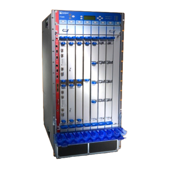
Juniper T1600 Quick Start Manual
Core router
Hide thumbs
Also See for T1600:
- Hardware manual (420 pages) ,
- Upgrade manual (56 pages) ,
- Installation (4 pages)
Table of Contents
Advertisement
Quick Links
T1600 Core Router Quick Start
January 2015
Part Number: 530-062016
Revision 01
Contents
Copyright © 2015, Juniper Networks, Inc.
This document describes how to install the Juniper Networks
Quick Start Description . . . . . . . . . . . . . . . . . . . . . . . . . . . . . . . . . . . . . . . . . . . . . . . 3
Step 1: Preparing the Site . . . . . . . . . . . . . . . . . . . . . . . . . . . . . . . . . . . . . . . . . . . . . . 4
Rack-Mounting Requirements . . . . . . . . . . . . . . . . . . . . . . . . . . . . . . . . . . . . . . 4
Step 2: Installing the Mounting Hardware . . . . . . . . . . . . . . . . . . . . . . . . . . . . . . . . . 7
Installing the Mounting Hardware for a Four-Post Rack or Cabinet . . . . . . . . . 7
Installing Cage Nuts, If Needed . . . . . . . . . . . . . . . . . . . . . . . . . . . . . . . . . . 8
Installing the Large Mounting Shelf and Spacer Bars . . . . . . . . . . . . . . . . 8
Installing the Small Mounting Shelf . . . . . . . . . . . . . . . . . . . . . . . . . . . . . . 9
Removing the Center-Mounting Brackets . . . . . . . . . . . . . . . . . . . . . . . . . . 9
Installing the Mounting Hardware in an Open-Frame Rack . . . . . . . . . . . . . . . 9
Installing Cage Nuts, If Needed . . . . . . . . . . . . . . . . . . . . . . . . . . . . . . . . . . 11
Installing the Large Mounting Shelf . . . . . . . . . . . . . . . . . . . . . . . . . . . . . . 11
Removing the Spacer Bars and Center-Mounting Brackets . . . . . . . . . . . 11
Step 3: Installing the T1600 Router . . . . . . . . . . . . . . . . . . . . . . . . . . . . . . . . . . . . . 12
Installing the Router Using a Lift . . . . . . . . . . . . . . . . . . . . . . . . . . . . . . . . . . . . 12
Installing the Router Without a Mechanical Lift . . . . . . . . . . . . . . . . . . . . . . . . 13
Removing Components . . . . . . . . . . . . . . . . . . . . . . . . . . . . . . . . . . . . . . . 14
Lifting the Router into the Rack . . . . . . . . . . . . . . . . . . . . . . . . . . . . . . . . . 16
Reinstalling Components . . . . . . . . . . . . . . . . . . . . . . . . . . . . . . . . . . . . . . 18
Step 4: Connecting the Grounding Cable . . . . . . . . . . . . . . . . . . . . . . . . . . . . . . . . . 19
Step 5: Connecting External Devices and PIC Cables . . . . . . . . . . . . . . . . . . . . . . . 20
Connecting to a Console or Auxiliary Device . . . . . . . . . . . . . . . . . . . . . . . . . . . 21
Connecting to a Network for Out-of-Band Management . . . . . . . . . . . . . . . . 22
Connecting the PIC Cables . . . . . . . . . . . . . . . . . . . . . . . . . . . . . . . . . . . . . . . . 23
Step 6: Connecting Power . . . . . . . . . . . . . . . . . . . . . . . . . . . . . . . . . . . . . . . . . . . . 25
Connecting Power to a T1600 Router with Three-Input 240-A DC Power
Supplies . . . . . . . . . . . . . . . . . . . . . . . . . . . . . . . . . . . . . . . . . . . . . . . . . . . 25
(Optional) . . . . . . . . . . . . . . . . . . . . . . . . . . . . . . . . . . . . . . . . . . . . . . 25
Setting the Input Mode Switch on a Three-Input 240-A DC Power
Supply . . . . . . . . . . . . . . . . . . . . . . . . . . . . . . . . . . . . . . . . . . . . . . . . . 27
®
T1600 Core Router.
1
Advertisement
Table of Contents

Subscribe to Our Youtube Channel
Related Manuals for Juniper T1600


Summary of Contents for Juniper T1600
-
Page 1: Table Of Contents
Step 3: Installing the T1600 Router ........ - Page 2 Supplies ........... 30 Connecting Power to a T1600 Router with Six-Input DC Power Supplies . . . 32 Connecting Power to a T1600 Router with Three-Phase Delta AC Power Supplies .
-
Page 3: Quick Start Description
Quick Start Description This Quick Start contains information you need to install and configure the router quickly. For complete installation instructions, see the T1600 Core Router Hardware Guide http://www.juniper.net/techpubs/hardware/ WARNING: This Quick Start contains a summary of safety warnings in “Safety... -
Page 4: Step 1: Preparing The Site
T1600 Core Router Hardware Guide Rack-Mounting Requirements on page 4 Tools Required to Unpack and Prepare the T1600 Router for Installation on page 5 Rack-Mounting Requirements You can install the router in many types of racks, including a four-post rack or cabinet or an open-frame rack. -
Page 5: Tools Required To Unpack And Prepare The T1600 Router For Installation
Tools Required to Unpack and Prepare the T1600 Router for Installation Figure 1: Rack Clearances and Router Dimensions Tools Required to Unpack and Prepare the T1600 Router for Installation A mechanical lift—recommended 1/2-in. or 13-mm open-end or socket wrench to remove bracket bolts from the shipping... - Page 6 T1600 Core Router Quick Start 1/4-in. slotted screwdriver to attach the ground wire and input terminal wires of the AC power cord. Wire cutters Cage nuts, if needed for your rack or cabinet Electrostatic discharge wrist strap Antistatic mat Blank panels to cover any slots not occupied by a component...
-
Page 7: Step 2: Installing The Mounting Hardware
Table 1: Four-Post Rack and Cabinet Mounting Hole Locations Hole Distance Above U Division Large Shelf Spacer Bars Small Shelf 34.75 in. (88.3 19.86 U – – 29.51 in. (74.9 16.86 U – – Copyright © 2015, Juniper Networks, Inc. -
Page 8: Installing Cage Nuts, If Needed
T1600 Core Router Quick Start Table 1: Four-Post Rack and Cabinet Mounting Hole Locations (continued) Hole Distance Above U Division Large Shelf Spacer Bars Small Shelf 24.26 in. (61.6 13.86 U – – 19.01 in. (48.3 10.86 U – 13.76 in. (34.9 7.86 U... -
Page 9: Installing The Small Mounting Shelf
Center-mounting: Attach the large mounting shelf on the back of the rails. The small mounting shelf is not needed for open-frame racks.Table 2 on page 10 specifies the holes in which you insert mounting screws and cage nuts (if needed). Copyright © 2015, Juniper Networks, Inc. - Page 10 T1600 Core Router Quick Start Figure 3: Mounting Hardware for an Open-Frame Rack An x in Table 2 on page 10 indicates a mounting hole location. Table 2: Open-Frame Rack Mounting Hole Locations Hole Distance Above U Division Large Shelf 34.13 in.
-
Page 11: Installing Cage Nuts, If Needed
If you plan to center-mount the router in an open-frame rack, leave the center-mounting brackets attached to the chassis. Optionally, you can remove the spacer bars from the front-mounting flanges. Copyright © 2015, Juniper Networks, Inc. -
Page 12: Step 3: Installing The T1600 Router
T1600 Core Router Quick Start Step 3: Installing the T1600 Router Because of the router's size and weight, we recommend that you install the router using a mechanical lift. If a lift is unavailable, see the instructions for installing the rack without a mechanical lift. -
Page 13: Installing The Router Without A Mechanical Lift
Open-frame rack: Install a mounting screw into each of the open mounting holes aligned with the rack, starting from the bottom. Reinstall the power supplies as described in the T1600 Core Router Hardware Guide Figure 4: Loading the Router onto the Lift Installing the Router Without a Mechanical Lift... -
Page 14: Removing Components
T1600 Core Router Quick Start Removing Components NOTE: For complete instructions on removing router components, see the T1600 Core Router Hardware Guide Before lifting the router, you must remove the following components (see the location of the components in Figure 5 on page 15... - Page 15 Removing Components Figure 5: Location of Components to Remove from the Front of the Router Front-mounting flange Center-mounting bracket Craft interface Fan tray FPCs ESD point Air filter Fan tray Air intake Copyright © 2015, Juniper Networks, Inc.
-
Page 16: Lifting The Router Into The Rack
T1600 Core Router Quick Start Figure 6: Location of Components to Remove from the Rear of the Router Lifting the Router into the Rack WARNING: Do not lift the router using the installation handle or the handles on the sides of the chassis. Use these handles only to help position the router. - Page 17 Open-frame rack: Install a mounting screw into each of the open mounting holes aligned with the rack, starting from the bottom. Figure 7: Lifting the Router into the Rack Copyright © 2015, Juniper Networks, Inc.
-
Page 18: Reinstalling Components
T1600 Core Router Quick Start Reinstalling Components NOTE: For complete instructions on reinstalling router components after you have installed the router without a mechanical lift, see the T1600 Core Router Hardware Guide Slide each component into the chassis evenly so that it does not become stuck or damaged. -
Page 19: Step 4: Connecting The Grounding Cable
Verify that the grounding cabling is correct, that the grounding cable does not touch or block access to router components, and that it does not drape where people could trip on it. Figure 8: Connecting the Grounding Cable Grounding points (on chassis) Copyright © 2015, Juniper Networks, Inc. -
Page 20: Step 5: Connecting External Devices And Pic Cables
T1600 Core Router Quick Start Step 5: Connecting External Devices and PIC Cables Figure 9: Connecting External Devices and PIC Cables To connect external devices and PIC cables, perform the following procedures: Connecting to a Console or Auxiliary Device on page 21... -
Page 21: Connecting To A Console Or Auxiliary Device
Flow control—none Using a 2.5-mm flat-blade screwdriver, tighten the screws on the connector. Attach the other end of the cable to the console or auxiliary device. Figure 10: Console and Auxiliary Serial Port Connector Copyright © 2015, Juniper Networks, Inc. -
Page 22: Connecting To A Network For Out-Of-Band Management
T1600 Core Router Quick Start Figure 11: Console and Auxiliary Ports on the CIP Connecting to a Network for Out-of-Band Management To connect the Routing Engine to a network for out-of-band management, connect an Ethernet with RJ-45 connectors to the port on the CIP. -
Page 23: Connecting The Pic Cables
RED ALARM YELLOW ALARM Connecting the PIC Cables WARNING: Do not look directly into the fiber-optic transceivers or into the ends of fiber-optic cables. Fiber-optic transceivers contain laser light sources that can damage your eyes. Copyright © 2015, Juniper Networks, Inc. - Page 24 T1600 Core Router Quick Start CAUTION: To prevent damage to fiber-optic transceivers and fiber-optic cables, observe the following precautions: Do not leave a fiber-optic transceiver uncovered except when inserting or removing cable. The safety cap keeps the port clean and prevents accidental exposure to laser light.
-
Page 25: Step 6: Connecting Power
26. Two optional cable restraints are shipped in the accessory box for the T1600 router. If your DC power cables are too large or inflexible to fit into the standard cable restraint, we recommend that you install the optional cable restraint (see Figure 15 on page 26) on each three-input 240-A DC power supply. - Page 26 T1600 Core Router Quick Start Figure 14: Three-Input 240-A DC Power Supply with the Standard Cable Retraint Figure 15: Three-Input 240-A Power DC Supply with the Optional Cable Restraint The cable restraint is located on the right edge of the power supply faceplate. To replace the cable restraints, follow this procedure: Loosen the captive screw on the standard cable restraint.
-
Page 27: Supply
Do not use a pencil, because fragments can break off and cause damage to the power supply. Rotate the metal cover over the input mode switch and use a screwdriver to tighten the captive screw. Copyright © 2015, Juniper Networks, Inc. -
Page 28: Connecting Dc Power Cables
T1600 Core Router Quick Start Connecting DC Power Cables Table 3: DC Power System Input Voltage Item Specification DC input Operating range: –40 to –72 VDC voltage NOTE: If the input voltage from the DC power source drops below –37.5 to –39.5 VDC, the routing platform automatically shuts down. - Page 29 Verify that the power cabling is correct, that the power cables are not touching or blocking access to router components, and that they do not drape where people could trip on them. Replace the clear plastic cover over the terminal studs on the faceplate. Copyright © 2015, Juniper Networks, Inc.
-
Page 30: Supplies
T1600 Core Router Quick Start Figure 17: Connecting Power to the Three-Input 240-A DC Power Supply Connecting Power to a T1600 Router with Four-Input 240-A DC Power Supplies Table 4: DC Power System Input Voltage Item Specification DC input Operating range: –40 to –72 VDC... - Page 31 Connecting Power to a T1600 Router with Four-Input 240-A DC Power Supplies To connect the DC source power cables to the router, follow this procedure for each DC power supply: Attach an electrostatic discharge (ESD) grounding strap to your bare wrist, and connect the strap to an approved site ESD grounding point.
-
Page 32: Connecting Power To A T1600 Router With Six-Input Dc Power Supplies
Locking washer Connecting Power to a T1600 Router with Six-Input DC Power Supplies You connect DC power to the router by attaching power cables from the DC power sources to the terminal studs on the power supply faceplates. You must provide power cables (the cable lugs are supplied with the router). - Page 33 Connecting Power to a T1600 Router with Six-Input DC Power Supplies CAUTION: You must use an appropriate torque-controlled tool to tighten the nuts. Applying excessive torque damages the terminal studs and the power supply. The absolute maximum torque that may be applied to this nut is 45 lb-in.
- Page 34 T1600 Core Router Quick Start driver, tighten the nuts. Apply between 23 lb-in. (2.6 Nm) and 25 lb-in. (2.8 Nm) of torque to each nut. Figure 19: Connecting DC Power Cables Cable lug Terminal studs Locking washer Figure 20: Connecting Negative (–) DC Power Cables to INPUT 0, INPUT 1,...
- Page 35 Connecting Power to a T1600 Router with Six-Input DC Power Supplies Figure 21: Connecting Negative (–) DC Power Cables to INPUT 2 and INPUT 5 Route the positive (+) DC source power cables for over the middle RTN 2 RTN 5 cable restraint.
-
Page 36: Supplies
Replace the clear plastic cover over the terminal studs on the faceplate. Connecting Power to a T1600 Router with Three-Phase Delta AC Power Supplies You connect AC power to the router with three-phase delta AC power supplies by connecting the AC power cord from an AC power supply to an AC power source. - Page 37 Connecting Power to a T1600 Router with Three-Phase Delta AC Power Supplies Connect the wires to the AC terminal block on the three-phase delta AC power supply (Figure 23 on page 37). Loosen the input terminal or grounding point screw, insert each wire into the grounding point or input terminal, and tighten the screw.
-
Page 38: Supplies
Repeat the procedure for the other three-phase delta AC power supply. Connecting Power to a T1600 Router with Three-Phase Wye AC Power Supplies To connect an AC power cord: Attach an electrostatic discharge (ESD) grounding strap to your bare wrist, and connect the strap to an approved site ESD grounding point. - Page 39 Connecting Power to a T1600 Router with Three-Phase Wye AC Power Supplies Connect the wires to the AC terminal block on the three-phase wye AC power supply (Figure 24 on page 39). Loosen each of the input terminals or grounding point screws, insert each wire into the grounding point or input terminal, and tighten the screw.
-
Page 40: Step 7: Powering On The Router
Powering On the AC-Powered Router on page 41 Powering On the DC-Powered Router You can use this procedure for a T1600 router for either three-input 240-A DC power supplies, four-input 240-A DC power supplies, or six-input DC power supplies. To power on the DC-powered router: Verify that the power supplies are fully inserted in the chassis and that the captive screws on their faceplates are tightened. -
Page 41: Powering On The Ac-Powered Router
DC cables. If you continue to have problems, see the replacement procedure for the power supply. Replacing a T1600 Three-Input 240-A DC Power Supply in the T1600 Core Router Hardware Guide Replacing a T1600 Four-Input 240-A DC Power Supply in the... - Page 42 T1600 Core Router Quick Start Turn on the power to the external management device. Switch on the dedicated customer site circuit breakers to provide power to the AC power cables. Follow your site’s procedures. Verify that the LED on both AC power supply faceplates are lit steadily green, AC OK indicating that the power supplies are receiving power.
-
Page 43: Step 8: Performing The Initial Software Configuration
Step 8: Performing the Initial Software Configuration Step 8: Performing the Initial Software Configuration The T1600 Core Router is shipped with the Junos OS preinstalled and ready to be configured when the T1600 router is powered on. These procedures connect a router to the network but do not enable it to forward traffic. -
Page 44: Configuring System Attributes
T1600 Core Router Quick Start [edit] root# set system root-authentication plain-text-password New password: password Retype new password: password Create a management console user account. [edit] root# set system login user user-name authentication plain-text-password New Password: password Retype new password: password... -
Page 45: Committing The Configuration
## Last changed: 2008-10-17 18:32:25 UTC version 9.1R1.8; groups { re0 { system { host-name spice-re0; interfaces { fxp0 { unit 0 { family inet { address 192.168.69.155/21; re1 { system { host-name spice-re1; Copyright © 2015, Juniper Networks, Inc. - Page 46 T1600 Core Router Quick Start interfaces { fxp0 { unit 0 { family inet { address 192.168.70.72/21; global; apply-groups [ re0 re1 ]; system { domain-name englab.juniper.net; backup-router 192.168.71.254; root-authentication { encrypted-password "xxxxxxxxxxx"; ## SECRET-DATA name-server { 192.168.1.1; login { user regress { uid 2001;...
- Page 47 (Optional) Configure additional properties by adding the necessary configuration statements. Then commit the changes to activate them. [edit] root@host# commit synchronize Exit configuration mode. [edit] root@host# exit Exiting configuration mode root> Copyright © 2015, Juniper Networks, Inc.
-
Page 48: Safety Warnings
For six-input DC power supplies, each 48 VDC facility DC source input power cable must be equipped with a current-limiting fuse or circuit breaker external to the Juniper Networks equipment rated at 100 A (–48 VDC) maximum, or as required by local code. -
Page 49: Compliance Statements For Nebs
The battery return connection is to be treated as an isolated DC return (i.e. DC-I), as defined in GR-1089-CORE. For Juniper systems with AC power supplies, an external surge protective device (SPD) must be used at the AC power source. -
Page 50: Compliance Statements For Emc Requirements
T1600 Core Router Quick Start Compliance Statements for EMC Requirements Canada on page 50 European Community on page 50 Israel on page 50 Japan on page 50 United States on page 50 Canada This Class A digital apparatus complies with Canadian ICES-003. -
Page 51: Junos Os Documentation And Release Notes
7 days a week, 365 days a year. Self-Help Online Tools and Resources For quick and easy problem resolution, Juniper Networks has designed an online self-service portal called the Customer Support Center (CSC) that provides you with the following features: Find CSC offerings: http://www.juniper.net/customers/support/... -
Page 52: Opening A Case With Jtac
Juniper Networks, Junos, Steel-Belted Radius, NetScreen, and ScreenOS are registered trademarks of Juniper Networks, Inc. in the United States and other countries. The Juniper Networks Logo, the Junos logo, and JunosE are trademarks of Juniper Networks, Inc. All other trademarks, service marks, registered trademarks, or registered service marks are the property of their respective owners.
Need help?
Do you have a question about the T1600 and is the answer not in the manual?
Questions and answers