Table of Contents
Advertisement
Quick Links
Advertisement
Table of Contents

Subscribe to Our Youtube Channel
Related Manuals for Digi IX10-00G4


Summary of Contents for Digi IX10-00G4
- Page 1 IX10 User Guide User Guide Firmware version 22.5...
-
Page 2: Revision History-90002399
Revision history—90002399 Revision Date Description Release of Digi IX10 firmware version 21.5: June 2021 Wi-Fi enhancements: Added support for WPA3 Wi-Fi encryption: WPA2/WPA3 Personal WPA3 Enhanced Open WPA3 Personal Added support for WPA and WPA/WPA2 mised mode with TKIP. Cellular enhancements: Added support for modem firmware update to the Admin CLI. - Page 3 September 2021 Added LXC container support for running localized containers on the device. Added support for maintenance windows triggers to control when a device is available for Digi Remote Manager maintenance activity. VPN enhancements: Added support for L2TPv3 tunneling. New option to enable, disable, or force IPsec IKE fragmentation.
- Page 4 MAC addresses. New monitoring metrics upload CLI command to send on-demand health metrics to Digi Remote Manager. Added support for the configuration of custom scripts that will be run manually, and a new system script start CLI command to run manual scripts.
- Page 5 Support for sending analog and digial I/O health metrics to Digi Remote Manager. Added show containers Admin CLI command. Release of Digi IX10 firmware version 22.2: March 2022 VPN enhancements: Renamed VPN > IPsec > Tunnels > Policies > Local network setting to Local traffic selector and added Remote traffic selector.
- Page 6 TCP socket connection is opened to the serial port. New cat Admin CLI command for displaying file contents. Release of Digi IX10 firmware version 22.5: June 2022 5G enhancements: Added 5G slice support for configuring the slice type for the 5G modems.
- Page 7 Trademarks and copyright Digi, Digi International, and the Digi logo are trademarks or registered trademarks in the United States and other countries worldwide. All other trademarks mentioned in this document are the property of their respective owners.
- Page 8 Customer support Gather support information: Before contacting Digi technical support for help, gather the following information: Product name and model Product serial number (s) Firmware version Operating system/browser (if applicable) Logs (from time of reported issue) Trace (if possible) Description of issue Steps to reproduce...
-
Page 9: Table Of Contents
Contents Revision history—90002399 What's new in Digi IX10 version 22.5 Digi IX10 Quick start Step 1: What's in the box Step 2: Gather accessories Step 3: Connect Apply Dielectric Grease over SIM Contacts Step 4: Configure Digi IX10 hardware reference Digi IX10 features and specifications... - Page 10 Enable event log upload to Digi Remote Manager Log into Digi Remote Manager Use Digi Remote Manager to view and manage your device Add a device to Digi Remote Manager Configure multiple IX10 devices by using Digi Remote Manager configurations...
- Page 11 Discover the IP address when connected to a network Discover the IP address when not on a network Manage the RealPort device list Access the web UI from the Digi Navigator Filter devices for display in the Digi Navigator Access Digi Remote Manager from the Digi Navigator...
- Page 12 Configure VRRP+ Example: VRRP/VRRP+ configuration Configure device one (master device) Configure device two (backup device) Show VRRP status and statistics Virtual Private Networks (VPN) IPsec IPsec data protection IPsec mode IPsec modes Internet Key Exchange (IKE) settings Authentication Configure an IPsec tunnel Configure IPsec failover Configure SureLink active recovery for IPsec Show IPsec status and statistics...
- Page 13 Configure telnet access Configure DNS Show DNS server Simple Network Management Protocol (SNMP) SNMP Security Configure Simple Network Management Protocol (SNMP) Download MIBs Location information Configure the location service Enable or disable modem GNSS support Configure the device to use a user-defined static location Configure the device to accept location messages from external sources Forward location information to a remote host Configure geofencing...
- Page 14 User authentication IX10 user authentication User authentication methods Add a new authentication method Delete an authentication method Rearrange the position of authentication methods Authentication groups Change the access rights for a predefined group Add an authentication group Delete an authentication group Local users Change a local user's password Configure a local user...
- Page 15 Test the custom container file System administration Review device status Configure system information Update system firmware Manage firmware updates using Digi Remote Manager Certificate management for firmware images Downgrading Dual boot behavior Update cellular module firmware Update modem firmware over the air (OTA)
- Page 16 Use the ping command to troubleshoot network connections Ping to check internet connection Stop ping commands Use the traceroute command to diagnose IP routing problems Digi IX10 regulatory and safety statements RF exposure statement Federal Communication (FCC) Part 15 Class B Radio Frequency Interference (RFI) (FCC 15.105)
- Page 17 Latvian--Latvietis Lithuanian--Lietuvis Polish--Polskie Portuguese--Português Slovak--Slovák Slovenian--Esloveno Spanish--Español DigiIX10 Certifications International EMC (Electromagnetic Compatibility) and safety standards Command line interface Access the command line interface Log in to the command line interface Exit the command line interface Execute a command from the web interface Display help for commands and parameters The help command The question mark (?) command...
- Page 18 help mkdir modem at modem at-interactive modem firmware check modem firmware list modem firmware ota check modem firmware ota list modem firmware ota update modem firmware update modem pin change modem pin disable modem pin enable modem pin status modem pin unlock modem puk status modem puk unlock modem reset...
- Page 19 show scripts show serial show surelink interface show surelink ipsec show surelink openvpn show system show usb show version show vrrp show web-filter speedtest system backup system disable-cryptography system duplicate-firmware system factory-erase system find-me system firmware ota check system firmware ota list system firmware ota update system firmware update system power ignition off_delay...
-
Page 20: What's New In Digi Ix10 Version 22.5
IPv4 networking to the device. Added suppport for Realport serial mode. Added the ability to configure CPU performance and power consumption. Added cellular APN and cellular connection duration as datapoints sent to Digi Remote Manager. Wi-Fi scanner enhancements: Added support for sending an HTTP or TCP stream of results from the Wi-Fi scanner to one or more remote servers. -
Page 21: Digi Ix10 Quick Start
When you open the IX10 package, look for the following: Digi IX10 device The Digi IX10 has a product label on the bottom of the device. The label includes product identification information and the default password assigned to the device. The IX10 also includes a terminal connector for the power supply installed in the power input. -
Page 22: Step 3: Connect
Name), and SIM pin (if any) for each card. Ethernet cable Smart phone or tablet Optional: Use a smart phone or table to to automatically register your IX10 in your Digi Remote Manager account and connect to your cellular network. See Digi IX10 Quick start. -
Page 23: Apply Dielectric Grease Over Sim Contacts
If the IX10 device is used in an environment with high vibration levels, SIM card contact fretting may cause unexpected SIM card failures. To protect the SIM cards, Digi strongly recommends that you apply a thin layer of dielectric grease to the SIM contacts prior to installing the SIM cards. - Page 24 Digi IX10 Quick start Apply Dielectric Grease over SIM Contacts be used as an alternative. c. Once the surface is clean and dry, apply a small amount of dielectric grease in a thin layer over the contacts. Use a new cotton-tipped applicator to work the grease smoothy over the contacts.
-
Page 25: Step 4: Configure
Step 4: Configure Step 4: Configure This section describes how to configure the device by using the local Web UI. You can also use Digi Remote Manager to configure the device, including using a Digi RM device configuration to automatically update the device. See the Digi Remote Manager User Guide. -
Page 26: Digi Ix10 Hardware Reference
Digi IX10 hardware reference Digi IX10 features and specifications The Digi IX10 key features include: Industrial grade components. Operating temperatures: -40C to +70C/-40F to +158F. LTE CAT 4 modem with two SIM slots. 10/100 BaseT Ethernet port for high-speed connectivity. For a detailed list of IX10 hardware specifications, see https://www.digi.com/products/networking/cellular-routers/industrial/digi-ix10#specifications. -
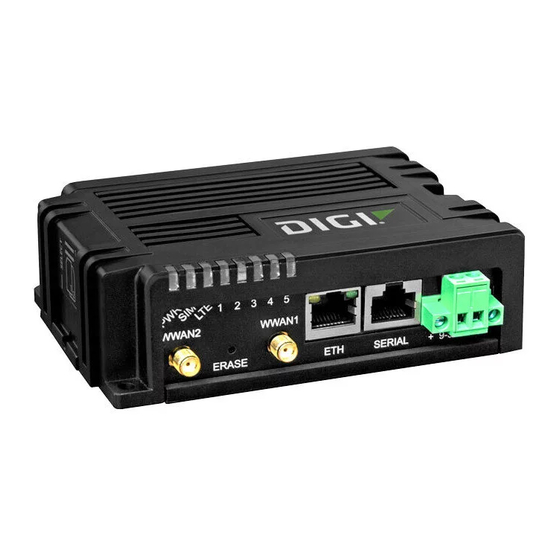
Page 27: Ix10 Leds
4. Ethernet LAN-enabled by default. port 5. Serial Digi IX10 serial connector pinout for information about the serial port pin-out. port 6. Power IX10 power supply requirements. -
Page 28: Power (Pwr)
Digi IX10 hardware reference IX10 LEDs Power (PWR) No power. Solid green DC power is connected to the device. Solid Blue Device is ON and connected to the internet. Indicates that a SIM is in use: No SIM is present Solid green SIM1 is active. -
Page 29: Signal Quality Indicators
Digi IX10 hardware reference IX10 LEDs Flashing green Solid green Connected to 2G or 3G and is in the Connected to 2G or 3G and also has process of connecting to any device a device linked to its ETH port. -
Page 30: Signal Quality Bars Explained
Solid amber: 10/100 Mbps link detected. Signal quality bars explained The signal status bars for the Digi IX10 measure more than simply signal strength. The value reported by the signal bars is calculated using an algorithm that takes into consideration the Reference Signals Received Power (RSRP), the Signal-to-noise ratio (SNR), and the Received Signal Strength Indication (RSSI) to provide an accurate indicator of the quality of the signal that the device is receiving. -
Page 31: Ix10 Power Supply Requirements
Use the Digi power supply accessory kit 76002104. If you are providing the DC power source with a non-Digi power supply, you must use a certified LPS power supply rated at either 12 VDC/0.75 A or 24 VDC/0.375 A minimum. The voltage tolerance supports +/- 10% (9 VDC to 30 VDC) at 9 Watts minimum. -
Page 32: 10-Pin Serial Cabling Options
QR code definition 10-pin serial cabling options Digi offers several cabling options for connecting a 10 pin RJ-45/RJ-50 serial port to DB9 and DB25 serial connectors. Digi recommends the RJ45/Bare Wire 48 inch cable, part number 76000723, which provides a customizable connector to connect EIA 422/485 Devices to Digi MEI products that have 10 pin RJ45 connectors. -
Page 33: Hardware Setup
Hardware setup This chapter contains the following topics: Install SIM cards Connect data cables Mount the IX10 device IX10 User Guide... -
Page 34: Install Sim Cards
If the IX10 device is used in an environment with high vibration levels, SIM card contact fretting may cause unexpected SIM card failures. To protect the SIM cards, Digi strongly recommends that you apply a thin layer of dielectric grease to the SIM contacts prior to installing the SIM cards. -
Page 35: Sim Removal
Serial (RJ-50): Use a serial cable with an RJ-50 connector to connect to the IX10 device. See pin serial cabling options for information about Digi's 10-pin RJ-50 cables. Mount the IX10 device There are two options for mounting the IX10 device: Attach to a mounting surface by using the mounting tabs. -
Page 36: Attach To A Mounting Surface By Using The Mounting Tabs
Hardware setup Mount the IX10 device Attach to a mounting surface by using the mounting tabs Attach to DIN rail with clip The DIN rail clip is an optional accessory included when the IX10 is purchased with accessories. You can attach the din rail clip directly to the device either on the back or the bottom of the device. 1. - Page 37 Hardware setup Mount the IX10 device b. Set the IX10 device onto a DIN rail and gently press until the clip snaps into the rail. 2. Attach the DIN rail clip to the bottom of the device: a. Attach the DIN rail clip to the bottom of the device with the screws provided. WARNING! Using screws longer than 5.0 mm will cause damage to the IX10.
- Page 38 Set the IX10 device onto a DIN rail and gently press until the clip snaps into the rail. WARNING! If being installed above head height on a wall or ceiling, ensure the device is fitted securely to avoid the risk of personal injury. Digi recommends that this device be installed by an accredited contractor.
- Page 39 This chapter contains the following topics: Review IX10 default settings Change the default password for the admin user Configuration methods Using Digi Remote Manager Using the local web interface Use the local REST API to configure the IX10 device Using the command line...
-
Page 40: Firmware Configuration
Firmware configuration Review IX10 default settings Review IX10 default settings You can review the default settings for your IX10 device by using the local WebUI or Digi Remote Manager: Local WebUI 1. Log into the IX10 WebUI as a user with Admin access. See Using the local web interface details. -
Page 41: Other Default Configuration Settings
Security policies Packet filtering allows all outbound traffic. SSH and web administration: Enabled for local administration Firewall zone: Internal Device heath metrics uploaded to Digi Remote Manager at 60 minute Monitoring interval. SNMP: Disabled Enabled Serial port Serial mode: Remote... - Page 42 Firmware configuration Change the default password for the admin user 1. Log into Digi Remote Manager, or log into the local Web UI as a user with full Admin access rights. 2. Access the device configuration: Remote Manager: a. Locate your device as described in Use Digi Remote Manager to view and manage your device.
-
Page 43: Configuration Methods
IX10 device. Note Changes made to the device's configuration by using the local web interface will not be automatically reflected in Digi Remote Manager. You must manually refresh Remote Manager for the changes to be displayed. IX10 User Guide... -
Page 44: Using Digi Remote Manager
Shows how to perform a task by using the command line interface. Using Digi Remote Manager By default, your IX10 device is configured to use Digi Remote Manager as its central management server. Devices must be registered with Remote Manager, either: As part of the getting started process. -
Page 45: Log Out Of The Web Interface
Firmware configuration Use the local REST API to configure the IX10 device Dashboard area Description Using Digi Remote Manager. Device Displays the IX10 device's status, statistics, and identifying information. Network Displays the status of the network interfaces configured on the device. - Page 46 Firmware configuration Use the local REST API to configure the IX10 device 2. At the command line, type config to enter configuration mode: > config (config)> 3. At the config prompt, type ? (question mark): (config)> ? auth Authentication cloud Central management firewall Firewall monitoring...
-
Page 47: Use The Post Method To Modify Device Configuration Parameters And List Arrays
Firmware configuration Use the local REST API to configure the IX10 device "result": { "type": "object", "path": "service.ssh" "collapsed": { "acl.zone.0": "internal" "acl.zone.1": "edge" "acl.zone.2": "ipsec" "acl.zone.3": "setup" "enable": "true" "key": "" "mdns.enable": "true" "mdns.name": "" "mdns.type": "_ssh._tcp." "port": "22" "protocol.0": "tcp" You can also use the GET method to return the configuration parameters associated with an item: curl -k -u admin https://192.168.210.1/cgi-bin/config.cgi/keys/service/ssh -X Enter host password for user 'admin':... -
Page 48: Use The Delete Method To Remove Items From A List Array
Firmware configuration Use the local REST API to configure the IX10 device $ curl -k -u admin "https://192.168.210.1/cgi- bin/config.cgi/value?path=service.ssh.enable&value=false" -X POST Enter host password for user 'admin': { "ok": true } Use the POST method to add items to a list array To add items to a list array, use the POST method with the path and append parameters. - Page 49 Firmware configuration Use the local REST API to configure the IX10 device "1": "edge" "2": "ipsec" "3": "setup" "4": "external" 2. Use the DELETE method to remove the external zone (list item 4). $ curl -k -u admin https://192.168.210.1/cgi- bin/config.cgi/value?path=service.ssh.acl.zone.4 -X DELETE Enter host password for user 'admin': { "ok": true } IX10 User Guide...
-
Page 50: Using The Command Line
You can use an open-source terminal software, such as PuTTY or TeraTerm, to access the device through one of these mechanisms. You can also access the command line interface in the WebUI by using the Terminal, or the Digi Remote Manager by using the Console. -
Page 51: Exit The Command Line Interface
Firmware configuration Using the command line Access selection menu: a: Admin CLI s: Shell q: Quit Select access or quit [admin] : Type a or admin to access the IX10 command line. You will now be connected to the Admin CLI: Connecting now... -
Page 52: Central Management
Configure your device for Digi Remote Manager support Log into Digi Remote Manager Use Digi Remote Manager to view and manage your device Add a device to Digi Remote Manager Configure multiple IX10 devices by using Digi Remote Manager configurations... -
Page 53: Digi Remote Manager Support
This URL is required to utilize the client-side certificate support. Prior to release 22.2.9.x, the default URL was my.devicecloud.com. If your Digi device is configured to use a non-default URL to connect to Remote Manager, updating the firmware will not change your configuration. However, if you erase the device's configuration, the Remote Manager URL will change to the default of edp12.devicecloud.com. - Page 54 HTTP proxy server support. To configure your device's Digi Remote Manager support: Web 1. Log into Digi Remote Manager, or log into the local Web UI as a user with full Admin access rights. 2. Access the device configuration: Remote Manager: a.
- Page 55 Digi Remote Manager support is enabled by default. To disable, toggle off Enable central management. 4. (Optional) For Service, select either Digi Remote Manager or Digi aView. The default is Digi Remote Manager. 5. (Optional) For Management server, type the URL for the central management server.
- Page 56 Central management Configure your device for Digi Remote Manager support 10. (Optional) For Allowed keep-alive misses, type the number of allowed keep-alive misses. The default is 3. 11. Enable watchdog is used to monitor the connection to remote cloud services. If the connection is down, you can configure the device to restart the connection, or to reboot.
- Page 57 Digi Remote Manager aview: Digi aView The default is Digi Remote Manager. 5. (Optional) Set the URL for the central management server. The default is the Digi Remote Manager server, my.devicecloud.com. (config)> cloud drm drm_url url (config)>...
- Page 58 8. (Optional) Set the amount of time that the IX10 device should wait between sending keep-alive messages to the Digi Remote Manager when using a cellular interface. Allowed values are from 30 seconds to two hours. The default is 290 seconds.
- Page 59 13. (Optional) Configure the IX10 device to communicate with remote cloud services by using SMS: a. Enable SMS messaging: (config)> cloud drm sms enable true (config)> b. Set the phone number for Digi Remote Manager: (config)> cloud drm sms destination drm_phone_number (config)> c. (Optional) Set the service identifier: (config)>...
-
Page 60: Collect Device Health Data And Set The Sample Interval
To disable the collection of device health data or enable it if it has been disabled, or to change the health sample interval: Web 1. Log into Digi Remote Manager, or log into the local Web UI as a user with full Admin access rights. 2. Access the device configuration: Remote Manager: a. - Page 61 3. Click Monitoring > Device Health. 4. (Optional) Click to expand Data point tuning. Data point tuning options allow to you configure what data are uploaded to the Digi Remote Manager. All options are enabled by default. 5. Only report changed values to Digi Remote Manager is enabled by default.
- Page 62 1, 5, 15, 30, or 60, and represents the number of minutes between uploads of health sample data. 5. By default, the device will only report health metrics values to Digi Remote Manager that have changed health metrics were last uploaded. This is useful to reduce the bandwidth used to report health metrics.
-
Page 63: Enable Event Log Upload To Digi Remote Manager
To enable the event log upload, or disable it if it has been disabled, and to change the upload interval: Web 1. Log into Digi Remote Manager, or log into the local Web UI as a user with full Admin access rights. 2. Access the device configuration: Remote Manager: a. - Page 64 Central management Configure your device for Digi Remote Manager support b. Click the Device ID. c. Click Settings. d. Click to expand Config. Web UI: a. On the menu, click System. Under Configuration, click Device Configuration. The Configuration window is displayed.
-
Page 65: Log Into Digi Remote Manager
1. If you have not already done so, click here to sign up for a Digi Remote Manager account. 2. Check your email for Digi Remote Manager login instructions. 3. Go to remotemanager.digi.com. 4. Log into your Digi Remote Manager account. -
Page 66: Use Digi Remote Manager To View And Manage Your Device
Use Digi Remote Manager to view and manage your device To view and manage your device: 1. If you have not already done so, connect to your Digi Remote Manager account. 2. From the menu, click Devices to display a list of your devices. -
Page 67: Configure Multiple Ix10 Devices By Using Digi Remote Manager Configurations
Configure multiple IX10 devices by using Digi Remote Manager configurations Digi recommends you take advantage of Remote Manager configurations to manage multiple IX10 devices. A Remote Manager configuration is a named set of device firmware, settings, and file system options. You use the configuration to automatically update multiple devices and to periodically scan devices to check for compliance with the configuration. -
Page 68: View Digi Remote Manager Connection Status
You can also include site-specific settings with a profile to override settings on a device-by-device basis. View Digi Remote Manager connection status To view the current Digi Remote Manager connection status from the local device: Web 1. Log into the IX10 WebUI as a user with Admin access. -
Page 69: Interfaces
Interfaces IX10 devices have several physical communications interfaces. These interfaces can be bridged in a Local Area Network (LAN) or assigned to a Wide Area Network (WAN). This chapter contains the following topics: Wireless Wide Area Networks (WWANs) Local Area Networks (LANs) Show Surelink status and statistics IX10 User Guide... -
Page 70: Wireless Wide Area Networks (Wwans)
Using Digi SureLink, you can configure the IX10 device to regularly probe connections through the modem to determine if the modem connection has failed. - Page 71 Interfaces Wireless Wide Area Networks (WWANs) Reset the modem. Reboot the device. The interval between connectivity tests. The number of probe attempts before the Modem interface is considered to have failed. The amount of time that the device should wait for a response to a probe attempt before considering it to have failed.
- Page 72 To configure the IX10 device to regularly probe connections through the WWAN: Web SureLink can be configured for both IPv4 and IPv6. 1. Log into Digi Remote Manager, or log into the local Web UI as a user with full Admin access rights. 2. Access the device configuration: Remote Manager: a.
- Page 73 Interfaces Wireless Wide Area Networks (WWANs) 4. Create a new WWAN or select an existing one: To create a new WWAN, see Configure a Wireless Wide Area Network (WWAN). To edit an existing WWAN, click to expand the appropriate WWAN. 5.
- Page 74 Interfaces Wireless Wide Area Networks (WWANs) 12. For Add Test Target, click . 13. Select the Test type: Test another interface's status: Allows you to test another interface's status, to create a failover or coupled relationship between interfaces. If Test another interface's status is selected: For Test Interface, select the alternate interface to be tested.
- Page 75 Interfaces Wireless Wide Area Networks (WWANs) b. If more than one test target is configured, for Success condition, determine whether the interface should fail over based on the failure of one of the test targets, or all of the test targets.
- Page 76 Interfaces Wireless Wide Area Networks (WWANs) To disable: (config network interface my_wwan ipv4 surelink)> restart false (config network interface my_wwan ipv4 surelink> (Optional) Set the number of times that the Surelink test must fail before the interface is restarted: (config network interface my_wwan ipv4 surelink)> restart_attempts (config network interface my_wwan ipv4 surelink>...
- Page 77 Interfaces Wireless Wide Area Networks (WWANs) Note If the reboot parameter is enabled at the same time as either the restart or reset_ modem parameters, the reboot parameter takes precedence. (Optional) Set the number of times that the Surelink test must fail before the device is rebooted: (config network interface my_wwan ipv4 surelink)>...
- Page 78 Interfaces Wireless Wide Area Networks (WWANs) (config network interface my_wwan ipv4 surelink target 0)> http_ url value (config network interface my_wwan ipv4 surelink target 0)> where value uses the format http[s]://hostname/[path] interface_up: The interface is considered to be down based on the interfaces down time, and the amount of time an initial connection to the interface takes before this test is considered to have failed.
- Page 79 Interfaces Wireless Wide Area Networks (WWANs) Set the expected status of the alternate interface: (config network interface my_wwan ipv4 surelink target 0)> other_status value (config network interface my_wwan ipv4 surelink target 0)> where value is either up or down. For example, if other_status is set to down, but the alternate interface is determined to be up, then this test will fail.
-
Page 80: Configure The Device To Reboot When A Failure Is Detected
To configure the IX10 device to reboot when an interface has failed: Web SureLink can be configured for both IPv4 and IPv6. 1. Log into Digi Remote Manager, or log into the local Web UI as a user with full Admin access rights. 2. Access the device configuration: Remote Manager:... - Page 81 Interfaces Wireless Wide Area Networks (WWANs) a. Locate your device as described in Use Digi Remote Manager to view and manage your device. b. Click the Device ID. c. Click Settings. d. Click to expand Config. Web UI: a. On the menu, click System. Under Configuration, click Device Configuration.
- Page 82 Interfaces Wireless Wide Area Networks (WWANs) SureLink can be enabled for both IPv4 and IPv6 configurations. By default, SureLink is enabled for IPv4 for the preconfigured WWAN (Modem). It is disabled for IPv6. 7. Restart interface is enabled by default. (Optional) For Restart fail count, type or select the number of times that the Surelink test must fail before the interface is restarted.
- Page 83 Interfaces Wireless Wide Area Networks (WWANs) Allowed values are any number of weeks, days, hours, minutes, or seconds, and take the format number{w|d|h|m|s}. For example, to set Initial connection time to ten minutes, enter 10m or 600s. The default is 60 seconds. 12.
- Page 84 Interfaces Wireless Wide Area Networks (WWANs) (config)> network interface my_wwan (config network interface my_wwan)> 4. Enable SureLink. SureLink can be enabled for both IPv4 and IPv6 configurations. By default, SureLink is enabled for IPv4 for the preconfigured WWAN (modem). It is disabled for IPv6. (config network interface my_wwan>...
- Page 85 Interfaces Wireless Wide Area Networks (WWANs) where value is one of: ping: Tests connectivity by sending an ICMP echo request to a specified hostname or IP address. Specify the hostname or IP address: (config network interface my_wwan ipv4 surelink target 0)> ping_ host host (config network interface my_wwan ipv4 surelink target 0)>...
- Page 86 Interfaces Wireless Wide Area Networks (WWANs) (config network interface my_wwan ipv4 surelink target 0)> interface_timeout value (config network interface my_wwan ipv4 surelink target 0)> The default is 60 seconds. other: Allows you to test another interface's status, to create a failover or coupled relationship between interfaces: (config network interface my_wwan ipv4 surelink target 0)>...
-
Page 87: Disable Surelink
You can also disable DNS lookup or other internet activity, while retaining the SureLink interface test. Web 1. Log into Digi Remote Manager, or log into the local Web UI as a user with full Admin access rights. 2. Access the device configuration: Remote Manager: a. - Page 88 Interfaces Wireless Wide Area Networks (WWANs) d. Click to expand Config. Web UI: a. On the menu, click System. Under Configuration, click Device Configuration. The Configuration window is displayed. 3. Click Network > Interfaces. 4. Select the appropriate WAN or WWAN on which SureLink should be disabled.. 5.
- Page 89 IP address assigned to it, that the physical link is up, and that a route is present to send traffic out of the network interface. Web 1. Log into Digi Remote Manager, or log into the local Web UI as a user with full Admin access rights. 2. Access the device configuration: Remote Manager: a.
- Page 90 Interfaces Wireless Wide Area Networks (WWANs) a. On the menu, click System. Under Configuration, click Device Configuration. The Configuration window is displayed. 3. Click Network > Interfaces. 4. Select the appropriate WAN or WWAN on which SureLink should be disabled.. 5.
- Page 91 Interfaces Wireless Wide Area Networks (WWANs) 8. Click the menu icon (...) next to the target and select Delete. 9. Click Apply to save the configuration and apply the change. Command line 1. Select the device in Remote Manager and click Actions > Open Console, or log into the IX10 local command line as a user with full Admin access rights.
-
Page 92: Using Cellular Modems In A Wireless Wan (Wwan)
SIM, the modem will attempt to reconnect to the SIM in the preferred SIM slot. To configure the modem: Web 1. Log into Digi Remote Manager, or log into the local Web UI as a user with full Admin access rights. 2. Access the device configuration: Remote Manager: a. - Page 93 Interfaces Wireless Wide Area Networks (WWANs) Web UI: a. On the menu, click System. Under Configuration, click Device Configuration. The Configuration window is displayed. 3. Click Network > Modems > Modem. 4. Modem are enabled by default. Click to toggle Enable to off to disable. 5.
- Page 94 Interfaces Wireless Wide Area Networks (WWANs) 6. For Active SIM slot, select the SIM slot that should be used by the modem, or select Any to use any SIM slot. The default is Any. 7. If Active SIM slot is set to Any, for Preferred SIM slot, select the SIM slot that should be considered the preferred slot for this modem, or select None.
- Page 95 Interfaces Wireless Wide Area Networks (WWANs) port: Applies this configuration to a modem attached to the identified physical port. If port is used, set modem's port: a. Determine available ports and correct syntax by using the ?: (config)> network modem modem port ? Match port: The physical port that the modem device is attached to.
- Page 96 Interfaces Wireless Wide Area Networks (WWANs) (config)> network modem modem max_intfs int (config)> 8. Carrier switching allows the modem to automatically match the carrier for the active SIM. Carrier switching is enabled by default. To disable: (config)> network modem modem carrier_switch false (config)>...
- Page 97 APN. To configure the APN: Web 1. Log into Digi Remote Manager, or log into the local Web UI as a user with full Admin access rights. 2. Access the device configuration: Remote Manager: a.
- Page 98 Interfaces Wireless Wide Area Networks (WWANs) 3. Click Network > Interfaces > Modem > APN list > APN. 4. For APN, type the Access Point Name (APN) to be used when connecting to the cellular carrier. 5. (Optional) IP version: For IP version, select one of the following: Automatic: Requests both IPv4 and IPv6 address.
- Page 99 Interfaces Wireless Wide Area Networks (WWANs) 2. At the command line, type config to enter configuration mode: > config (config)> 3. At the config prompt, type: (config)> network interface modem modem apn 0 apn value (config)> where value is the APN for the SIM card. 4.
- Page 100 Interfaces Wireless Wide Area Networks (WWANs) 7. (Optional) To configure the device to bypass its preconfigured APN list and only use the configured APNs: (config)> network interface modem modem apn_lock true (config)> 8. Save the configuration and apply the change: (config)>...
- Page 101 Interfaces Wireless Wide Area Networks (WWANs) ----------- IMEI : 781154796325698 Model : LM940 FW Version : 24.01.541_ATT Revision : 24.01.541 Status ------ State : connected Signal Strength : Good (-85 dBm) Bars : 2/5 Access Mode : 4G Network Technology (CNTI): LTE Band : B2 Temperature...
- Page 102 Interfaces Wireless Wide Area Networks (WWANs) Unlock a SIM card A SIM card can be locked if a user tries to set an invalid PIN for the SIM card too many times. In addition, some cellular carriers require a SIM PIN to be added before the SIM card can be used. If the SIM card is locked, the IX10 device cannot make a cellular connection.
- Page 103 If the signal strength LEDs or the signal quality for your device indicate Poor or No service, try the following things to improve signal strength: Move the IX10 device to another location. Try connecting a different set of antennas, if available. Purchase a Digi Antenna Extender Kit: Antenna Extender Kit, 1m Antenna Extender Kit, 3m AT command access To run AT commands from the IX10 command line: ...
- Page 104 APNs, and then use routing roles to forward traffic to the appropriate WWAN interface. Web 1. Log into Digi Remote Manager, or log into the local Web UI as a user with full Admin access rights. 2. Access the device configuration: Remote Manager: a.
- Page 105 Interfaces Wireless Wide Area Networks (WWANs) c. Click Settings. d. Click to expand Config. Web UI: a. On the menu, click System. Under Configuration, click Device Configuration. The Configuration window is displayed. 3. Increase the maximum number of interfaces allowed for the modem: a.
- Page 106 Interfaces Wireless Wide Area Networks (WWANs) d. For Zone, select External. e. For Device, select Modem . f. (Optional): Configure the public APN. If the public APN is not configured, the IX10 will attempt to determine the APN. i. Click to expand APN list > APN. ii.
- Page 107 Interfaces Wireless Wide Area Networks (WWANs) m. For APN, type the private APN provided to you by your cellular carrier. 5. Create the routing policies. For example, to route all traffic from a device with the IP address of 192.168.2.101 through the private APN: a.
- Page 108 Interfaces Wireless Wide Area Networks (WWANs) iii. For Interface, select Interface: WWAN_Private. 6. Click Apply to save the configuration and apply the change. Command line 1. Select the device in Remote Manager and click Actions > Open Console, or log into the IX10 local command line as a user with full Admin access rights.
- Page 109 Interfaces Wireless Wide Area Networks (WWANs) e. Use to periods (..) to move back one level in the configuration: (config network interface WWANPublic)> .. (config network interface)> f. Create the WWANPrivate interface: (config network interface)> add WWANPrivate (config network interface WWANPrivate)> g.
-
Page 110: Configure A Wireless Wide Area Network (Wwan)
Interfaces Wireless Wide Area Networks (WWANs) ii. Set the IP address to 192.168.2.101: (config network route policy 0)> src address 192.168.2.101 (config network route policy 0)> e. Configure the destination address: i. Set the type to interface: (config network route policy 1)> dst type interface (config network route policy 1)>... - Page 111 Web 1. Log into Digi Remote Manager, or log into the local Web UI as a user with full Admin access rights. 2. Access the device configuration: Remote Manager: a. Locate your device as described in Use Digi Remote Manager to view and manage your device.
- Page 112 Interfaces Wireless Wide Area Networks (WWANs) 3. Click Network > Interfaces. 4. Create the WWAN or select an existing WWAN: To create a new WWAN, for Add interface, type a name for the WWAN and click . To edit an existing WWAN, click to expand the WWAN. New WWANs are enabled by default.
- Page 113 Interfaces Wireless Wide Area Networks (WWANs) If SIM slot is selected, for Match SIM slot, select which SIM slot must be in active for this WWAN to be used. If Carrier is selected, for Match SIM carrier, select which cellular carrier must be in active for this WWAN to be used.
- Page 114 Interfaces Wireless Wide Area Networks (WWANs) 16. For APN list and APN list only, the IX10 device uses a preconfigured list of Access Point Names (APNs) when attempting to connect to a cellular carrier for the first time. After the device has successfully connected, it will remember the correct APN.
- Page 115 Interfaces Wireless Wide Area Networks (WWANs) Depending on your device configuration, you may be presented with an Access selection menu. Type admin to access the Admin CLI. 2. At the command line, type config to enter configuration mode: > config (config)>...
- Page 116 Interfaces Wireless Wide Area Networks (WWANs) a. Use ? to determine available carriers: (config network interface my_wwan)> modem carrier Match SIM carrier: The SIM carrier match criteria. This interface is applied when the SIM card is provisioned from the carrier. Format: AT&T Rogers...
- Page 117 Interfaces Wireless Wide Area Networks (WWANs) 7. Set the PIN for the SIM. Leave blank if no PIN is required. (config network interface my_wwan)> modem pin value (config network interface my_wwan)> 8. Set the phone number for the SIM, for SMS connections: (config network interface my_wwan)>...
- Page 118 Interfaces Wireless Wide Area Networks (WWANs) Note If manual is configured forthe carrier selection mode and a specific network technology is selected for the cellular network technology, your modem must support the selected technology or no cellular connection will be established. If you are using a cellular connection to perform this procedure, you may lose your connection and the device will no longer be accessible.
- Page 119 Interfaces Wireless Wide Area Networks (WWANs) 14. Optional IPv4 configuration items: a. IPv4 support is enabled by default. To disable: (config network interface my_wwan)> ipv4 enable false (config network interface my_wwan)> b. Set the MTU: (config network interface my_wwan)> ipv4 mtu num (config network interface my_wwan)>...
-
Page 120: Show Wwan Status And Statistics
Interfaces Wireless Wide Area Networks (WWANs) Show WWAN status and statistics Web 1. Log into the IX10 WebUI as a user with Admin access. 2. From the menu, click Status. 3. Under Networking, click Interfaces. Command line 1. Select the device in Remote Manager and click Actions > Open Console, or log into the IX10 local command line as a user with full Admin access rights. -
Page 121: Delete A Wwan
WAN, ETH1, or the preconfigured WWAN, Modem. Web 1. Log into Digi Remote Manager, or log into the local Web UI as a user with full Admin access rights. 2. Access the device configuration: Remote Manager:... - Page 122 Interfaces Wireless Wide Area Networks (WWANs) a. Locate your device as described in Use Digi Remote Manager to view and manage your device. b. Click the Device ID. c. Click Settings. d. Click to expand Config. Web UI: a. On the menu, click System. Under Configuration, click Device Configuration.
- Page 123 Interfaces Wireless Wide Area Networks (WWANs) (config)> del network interface my_wwan 4. Save the configuration and apply the change: (config)> save Configuration saved. > 5. Type exit to exit the Admin CLI. Depending on your device configuration, you may be presented with an Access selection menu.
-
Page 124: Local Area Networks (Lans)
Interfaces Local Area Networks (LANs) Local Area Networks (LANs) The IX10 device is preconfigured with the following Local Area Networks (LANs): Interface type Preconfigured interfaces Devices Default configuration Local Area Ethernet: Firewall zone: Network Internal (LAN) IP Address: 192.168.2.1/24 DHCP server enabled LAN priority: Metric=5... -
Page 125: About Local Area Networks (Lans)
Interfaces Local Area Networks (LANs) About Local Area Networks (LANs) A Local Area Network (LAN) connects network devices together in a logical Layer-2 network. The following diagram shows a LAN connected to the ETH Ethernet device. Once the LAN is configured and enabled, the devices connected to the network interfaces can communicate with each other, as demonstrated by the ping commands. - Page 126 To create a new LAN or edit an existing LAN: Web 1. Log into Digi Remote Manager, or log into the local Web UI as a user with full Admin access rights. 2. Access the device configuration: Remote Manager: a.
- Page 127 Interfaces Local Area Networks (LANs) 4. Create the LAN or select an existing LAN: To create a new LAN, for Add interface, type a name for the LAN and click . To edit an existing LAN, click to expand the LAN. The Interface configuration window is displayed.
- Page 128 Interfaces Local Area Networks (LANs) c. For Address, type the IP address and subnet of the LAN interface. Use the format IPv4_ address/netmask, for example, 192.168.2.1/24. d. Optional IPv4 configuration items: i. Set the MTU. e. Enable the DHCP server: i.
- Page 129 Interfaces Local Area Networks (LANs) 3. Create a new LAN or edit an existing one: To create a new LAN named my_lan: (config)> add network interface my_lan (config network interface my_lan)> To edit an existing LAN named my_lan, change to the my_lan node in the configuration schema: (config)>...
- Page 130 Interfaces Local Area Networks (LANs) (config network interface my_lan)> ipv4 address ip_address/netmask (config network interface my_lan)> b. Optional IPv4 configuration items: i. Set the MTU: (config network interface my_lan)> ipv4 mtu num (config network interface my_lan)> c. Enable the DHCP server: (config network interface my_lan)>...
- Page 131 Interfaces Local Area Networks (LANs) View default settings for the IPv6 DHCP server: (config network interface my_lan)> ipv6 dhcpv6_server ? DHCPv6 server: The DHCPv6 server settings for this network interface. Parameters Current Value --------------------------------------------------------------------- ---------- enable true Enable (config network interface my_lan)> d.
- Page 132 Interfaces Local Area Networks (LANs) f. (Optional) Configure 802.1x authentication auditing: i. Enable authentication auditing on the IX10 device: (config network interface my_lan)> 802_1x accounting enable true (config network interface my_lan)> ii. Set the IP address of the accounting server: (config network interface my_lan)>...
-
Page 133: Change The Default Lan Subnet
DHCP server range will also change to the range of the LAN subnet. To change the LAN subnet: Web 1. Log into Digi Remote Manager, or log into the local Web UI as a user with full Admin access rights. 2. Access the device configuration: Remote Manager: a. -
Page 134: Change The Lan Address Type
By default, the LAN interface uses a static IP address. To configure it to use a DHCP address instead: Web 1. Log into Digi Remote Manager, or log into the local Web UI as a user with full Admin access rights. 2. Access the device configuration: Remote Manager: a. - Page 135 Interfaces Local Area Networks (LANs) a. On the menu, click System. Under Configuration, click Device Configuration. The Configuration window is displayed. 3. Click Network > Interfaces > LAN > IPv4. 4. For the Type option, select DHCP address. 5. Click Apply to save the configuration and apply the change. ...
-
Page 136: Show Lan Status And Statistics
Interfaces Local Area Networks (LANs) Show LAN status and statistics Web 1. Log into the IX10 WebUI as a user with Admin access. 2. From the menu, click Status. 3. Under Networking, click Interfaces. Command line 1. Select the device in Remote Manager and click Actions > Open Console, or log into the IX10 local command line as a user with full Admin access rights. -
Page 137: Delete A Lan
Follow this procedure to delete any LANs that have been added to the system. You cannot delete the preconfigured LAN, LAN1. Web 1. Log into Digi Remote Manager, or log into the local Web UI as a user with full Admin access rights. 2. Access the device configuration: Remote Manager:... - Page 138 Interfaces Local Area Networks (LANs) a. Locate your device as described in Use Digi Remote Manager to view and manage your device. b. Click the Device ID. c. Click Settings. d. Click to expand Config. Web UI: a. On the menu, click System. Under Configuration, click Device Configuration.
-
Page 139: Dhcp Servers
Interfaces Local Area Networks (LANs) 4. Save the configuration and apply the change: (config)> save Configuration saved. > 5. Type exit to exit the Admin CLI. Depending on your device configuration, you may be presented with an Access selection menu. Type quit to disconnect from the device. DHCP servers You can enable DHCP on your IX10 device to assign IP addresses to clients, using either: The DHCP server for the device's local network, which assigns IP addresses to clients on the... - Page 140 Interfaces Local Area Networks (LANs) Web 1. Log into Digi Remote Manager, or log into the local Web UI as a user with full Admin access rights. 2. Access the device configuration: Remote Manager: a. Locate your device as described in Use Digi Remote Manager to view and manage your device.
- Page 141 Interfaces Local Area Networks (LANs) address (the final triplet in an IPv4 address, for example, 192.168.2.xxx). The remainder of the IP address will be based on the LAN's static IP address as defined in the Address field. Allowed values are between 1 and 254, and the default is 100 for Lease range start and 250 for Lease range end.
- Page 142 Interfaces Local Area Networks (LANs) (config)> network interface my_lan ipv4 dhcp_server enable true (config)> Configure a LAN for information about creating a LAN. 4. (Optional) Set the amount of time that a DHCP lease is valid: (config)> network interface my_lan ipv4 dhcp_server lease_time value (config)>...
- Page 143 Interfaces Local Area Networks (LANs) The default is auto. c. Determine how the DHCP server should broadcast the the MTU: (config)> network interface my_lan ipv4 dhcp_server advanced mtu value (config)> where value is one of: none: An MTU of length 0 is broadcast. This is not recommended. auto: No MTU is broadcast and clients will determine their own MTU.
- Page 144 A label for this instance of the static lease. To map static IP addresses: Web 1. Log into Digi Remote Manager, or log into the local Web UI as a user with full Admin access rights. 2. Access the device configuration: Remote Manager: a.
- Page 145 Interfaces Local Area Networks (LANs) d. Click to expand Config. Web UI: a. On the menu, click System. Under Configuration, click Device Configuration. The Configuration window is displayed. 3. Click Network > Interfaces. 4. Click to expand an existing LAN, or create a new LAN. See Configure a LAN.
- Page 146 Interfaces Local Area Networks (LANs) 2. At the command line, type config to enter configuration mode: > config (config)> 3. Add a static lease to the DHCP server configuration for an existing LAN. For example, to add static lease to a LAN named my_lan: (config)>...
- Page 147 Delete static IP mapping entries To delete a static IP entry: Web 1. Log into Digi Remote Manager, or log into the local Web UI as a user with full Admin access rights. 2. Access the device configuration: Remote Manager:...
- Page 148 Interfaces Local Area Networks (LANs) a. Locate your device as described in Use Digi Remote Manager to view and manage your device. b. Click the Device ID. c. Click Settings. d. Click to expand Config. Web UI: a. On the menu, click System. Under Configuration, click Device Configuration.
- Page 149 Interfaces Local Area Networks (LANs) 3. Show the static lease configuration. For example, to show the static leases for a lan named my_lan: (config)> show network interface my_lan ipv4 dhcp_server advanced static_ lease ip 192.168.2.10 mac BF:C3:46:24:0E:D9 no name ip 192.168.2.11 mac E3:C1:1F:65:C3:0E no name (config)>...
- Page 150 Interfaces Local Area Networks (LANs) 1. Log into Digi Remote Manager, or log into the local Web UI as a user with full Admin access rights. 2. Access the device configuration: Remote Manager: a. Locate your device as described in Use Digi Remote Manager to view and manage your device.
- Page 151 Interfaces Local Area Networks (LANs) 12. Click Apply to save the configuration and apply the change. Command line 1. Select the device in Remote Manager and click Actions > Open Console, or log into the IX10 local command line as a user with full Admin access rights. Depending on your device configuration, you may be presented with an Access selection menu.
- Page 152 Interfaces Local Area Networks (LANs) (config network interface my_lan ipv4 dhcp_server advanced custom_option 0)> force true (config network interface my_lan ipv4 dhcp_server advanced custom_option 0)> 9. (Optional) Set the data type that the option uses. If the incorrect data type is selected, the device will send the value as a string. (config network interface my_lan ipv4 dhcp_server advanced custom_option 0)>...
- Page 153 Additional configuration items IP address of additional DHCP relay servers. Web 1. Log into Digi Remote Manager, or log into the local Web UI as a user with full Admin access rights. 2. Access the device configuration: Remote Manager: a.
- Page 154 Interfaces Local Area Networks (LANs) 9. Repeat for each additional DHCP relay server. 10. Click Apply to save the configuration and apply the change. Command line 1. Select the device in Remote Manager and click Actions > Open Console, or log into the IX10 local command line as a user with full Admin access rights.
- Page 155 Interfaces Local Area Networks (LANs) 6. Save the configuration and apply the change: (config network interface lan1 ipv4 dhcp_relay 1)> save Configuration saved. > 7. Type exit to exit the Admin CLI. Depending on your device configuration, you may be presented with an Access selection menu.
-
Page 156: Create A Virtual Lan (Vlan) Route
The VLAN ID. The TCP header uses the VLAN ID to identify the destination VLAN for the packet. To create a VLAN: Web 1. Log into Digi Remote Manager, or log into the local Web UI as a user with full Admin access rights. 2. Access the device configuration: Remote Manager: a. - Page 157 Interfaces Local Area Networks (LANs) 3. Click Network > Virtual LAN. 4. Type a name for the VLAN and click . 5. Select the Device. 6. Type or select a unique numeric ID for the VLAN ID. 7. Click Apply to save the configuration and apply the change. ...
-
Page 158: Show Surelink Status And Statistics
Interfaces Show Surelink status and statistics b. Add the device: (config network vlan vlan1)> device /network/device/ (config network vlan vlan1)> 5. Set the VLAN ID: (config network vlan vlan1)> id value where value is an integer between 1 and 4095. 6. Save the configuration and apply the change: (config network vlan vlan1)>... -
Page 159: Show Surelink Status For A Specific Interface
Interfaces Show Surelink status and statistics 3. Type exit to exit the Admin CLI. Depending on your device configuration, you may be presented with an Access selection menu. Type quit to disconnect from the device. Show Surelink status for a specific interface To show the Surelink status a specific interface, use the show surelink interface name name command:... -
Page 160: Show Surelink Status For A Specific Ipsec Tunnel
Interfaces Show Surelink status and statistics 3. Type exit to exit the Admin CLI. Depending on your device configuration, you may be presented with an Access selection menu. Type quit to disconnect from the device. Show Surelink status for a specific IPsec tunnel To show the Surelink status a specific IPsec tunnel, use the show surelink ipsec tunnel name command:... -
Page 161: Show Surelink Status For A Specific Openvpn Client
Interfaces Show Surelink status and statistics 3. Type exit to exit the Admin CLI. Depending on your device configuration, you may be presented with an Access selection menu. Type quit to disconnect from the device. Show Surelink status for a specific OpenVPN client To show the Surelink status a specific OpenVPN client, use the show surelink openvpn client name command:... -
Page 162: Serial Port
Access: Provides socket level access to ports. Application: Provides access to the serial device from Python applications. RealPort: Used in conjunction with the Digi RealPort driver. RealPort can also be configured using the Digi Navigator. For more information about configuring RealPort, see Digi Navigator application. -
Page 163: Configure Login Mode
Serial port Configure Login mode Parity: None Stop bits: 1 Flow control: None Configure Login mode Login mode allows the user to log into the device through the serial port. To change the configuration to match the serial configuration of the device to which you want to connect: ... - Page 164 Serial port Configure Login mode 7. Expand Serial Settings. The entries in the following fields must match the information for the power controller. Refer to your power controller manual for the correct entries. a. Baud rate: For Baud rate, select the baud rate used by the device to which you want to connect.
- Page 165 Serial port Configure Login mode 5. Set the signaling interface type used on this serial port: rs-232 rs-485 Enable termination if you want to enable electrical termination on this serial port: (config)> serial port1 termination true (config)> The default is rs-232. 6.
-
Page 166: Configure Remote Access Mode
Serial port Configure Remote Access mode 12. Save the configuration and apply the change: (config)> save Configuration saved. > 13. Type exit to exit the Admin CLI. Depending on your device configuration, you may be presented with an Access selection menu. - Page 167 Serial port Configure Remote Access mode 6. For Signalling, select the electrical signaling interface type used on this serial port: RS-232 RS-485 Enable Termination if you want to enable electrical termination on this serial port. The default is RS-232. 7. Expand Serial Settings. The entries in the following fields must match the information for the power controller.
- Page 168 Serial port Configure Remote Access mode d. For Destination, enter the host name or IP address of the remote server. When using SSH, this should be prefixed with the user name and followed by @. e. For IP Port, enter the TCP port of the remote server (1-65535). f.
- Page 169 Serial port Configure Remote Access mode 3. The serial port is enabled by default. To disable: (config)> serial port1 enable false (config)> 4. Set the mode: (config)> serial port1 mode remoteaccess (config)> 5. Set the signaling interface type used on this serial port: rs-232 rs-485 Enable termination if you want to enable electrical termination on this serial port:...
- Page 170 Serial port Configure Remote Access mode 11. Set the type of flow control used by the device to which you want to connect: (config)>path-paramflow value (config)> where value is one of: none rts/cts xon/xoff 12. Configure the session settings. a. Set the characters used to start an escape sequence: (config)>path-paramescape string (config) If no characters are defined, the escape sequence is disabled.
-
Page 171: Configure Application Mode
Serial port Configure Application mode b. (Optional) Enable monitoring of DCD (Data Carrier Detect) changes on this port: (config)>path-parammonitor dcd true (config) 14. Save the configuration and apply the change: (config)> save Configuration saved. > 15. Type exit to exit the Admin CLI. Depending on your device configuration, you may be presented with an Access selection menu. - Page 172 Serial port Configure Application mode The serial port is enabled by default. To disable, toggle off Enable. 4. For Mode, select Application. The default is Remote. 5. (Optional) For Label, enter a label that will be used when referring to this port. 6.
-
Page 173: Configure Ppp Dial-In Mode
To change the configuration to match the serial configuration of the device to which you want to connect: Web 1. Log into Digi Remote Manager, or log into the local Web UI as a user with full Admin access rights. 2. Access the device configuration: Remote Manager: a. - Page 174 Serial port Configure PPP dial-in mode The Configuration window is displayed. 3. Click to expand the name of the port that you want to configure, for example, Port 1. The serial port is enabled by default. To disable, toggle off Enable. 4.
- Page 175 Serial port Configure PPP dial-in mode None: No authentication is required. Automatic: Attempt to authenticate using CHAP first, and then PAP. CHAP: Use Challenge Handshake Authentication Protocol (CHAP) to authenticate. PAP: Use Password Authentication Protocol (PAP) to authenticate. If Automatic, CHAP, or PAP are selected, type the Username and Password used to authenticate the remote peer.
- Page 176 Serial port Configure PPP dial-in mode exit 0 # start up the local PPP session AT*) echo "OK" # passively accept any other AT command esac done 17. Click Apply to save the configuration and apply the change. The Apply button is located at the top of the WebUI page. You may need to scroll to the top of the page to locate it.
- Page 177 Serial port Configure PPP dial-in mode 6. Set the baud rate used by the device to which you want to connect: (config)> serial port1 baudrate rate (config)> 7. Set the type of flow control used by the device to which you want to connect: (config)>...
- Page 178 Serial port Configure PPP dial-in mode (config)> serial port1 ppp_dialin username username (config)> serial port1 ppp_dialin password password (config)> 12. Set the priority of routes associated with this interface. If there are multiple active routes that match a destination, then the route with the lowest metric will be used. (config)>...
- Page 179 Serial port Configure PPP dial-in mode (config)> serial port1 ppp_dialin custom override true (config)> If override is not enabled, the custom PPP configuration file is used in addition to the default configuration. c. Paste or type the configuration data in the format of a pppd options file: (config)>...
-
Page 180: Configure Realport Mode
3. Click the desired RealPort for Windows version. The file is downloaded, and a Windows Explorer window launches, showing the RealPort files. 4. When the download is complete, open the .zip file and click the setup.exe file. The Digi RealPort Setup Wizard appears. - Page 181 Serial port Configure RealPort mode 5. Select Add a New Device. 6. Follow the steps in the wizard to install RealPort. 7. Click Finish to close the wizard. Step 2: Configure Encrypted RealPort Encrypted RealPort is a security feature that maintains data integrity. It prevents unauthorized changes in data, including intentional destruction or alteration, tampering, duplication, or accidental loss.
-
Page 182: Configure The Serial Port For Realport Mode
Serial port Configure RealPort mode on the device. a. Open browser window. b. Enter the IP address in the URL address bar to access the web interface. c. Choose Network > Network Services Settings. d. Select the Enable Encrypted RealPort option and verify that the port number is 1027. e. - Page 183 Serial port Configure RealPort mode 6. (Optional) For Label, enter a label that will be used when referring to this port. 7. For Signalling, select the electrical signaling interface type used on this serial port: RS-232 RS-485 Enable Termination if you want to enable electrical termination on this serial port. The default is RS-232.
-
Page 184: Configure The Realport Service
Serial port Configure RealPort mode rs-232 rs-485 Enable termination if you want to enable electrical termination on this serial port: (config)> serial port1 termination true (config)> The default is rs-232. 5. Set a label that will be used when referring to this port. (config)>... -
Page 185: Configure Udp Serial Mode
Serial port Configure UDP serial mode 11. Enable TCP Port Keepalive to send TCP keepalive packets. This is disabled by default. 12. Click Apply to save the configuration and apply the change. The Apply button is located at the top of the WebUI page. You may need to scroll to the top of the page to locate it. - Page 186 Serial port Configure UDP serial mode RS-232 RS-485 Enable Termination if you want to enable electrical termination on this serial port. The default is RS-232. 7. Expand Serial Settings. a. For Baud rate, select the baud rate used by the device to which you want to connect. b.
- Page 187 Serial port Configure UDP serial mode 9. Expand UDP Serial Settings. a. For Local port, enter the UDP port. The default is 4001 or serial port 1, 4002 for serial port 2, etc. b. (Optional) For Socket String ID, enter a string that should be added at the beginning of each packet.
- Page 188 Serial port Configure UDP serial mode Depending on your device configuration, you may be presented with an Access selection menu. Type admin to access the Admin CLI. 2. At the command line, type config to enter configuration mode: > config (config)>...
- Page 189 Serial port Configure UDP serial mode 10. Set the stop bits used by the device to which you want to connect: (config)>serial port1 label stopbits bits (config)> 11. Set the type of flow control used by the device to which you want to connect: (config)>serial port1 label flow type (config) Allowed values are:...
-
Page 190: Configure Modbus Mode
Serial port Configure Modbus mode 18. (Optional) Enter a string that should be added at the beginning of each packet: (config)> serial port1 udp socketid backslash-escaped-string (config)> 19. Configure the remote sites to which you want to send data. If you do not specify any destinations, the IX10 send new data to the last hostname and port from which data was received. - Page 191 Serial port Configure Modbus mode 1. Log into the IX10 WebUI as a user with Admin access. 2. On the menu, click System. Under Configuration, click Serial Configuration. The Serial Configuration page is displayed. Note You can also configure the serial port by using Device Configuration > Serial. Changes made by using either Device Configuration or Serial Configuration will be reflected in both.
- Page 192 Serial port Configure Modbus mode d. Stop bits: For Stop bits, select the number of stop bits used by the device to which you want to connect. The default is 1. e. Flow control: For Flow control, select the type of flow control used by the device to which you want to connect.
- Page 193 Serial port Configure Modbus mode Command line 1. Select the device in Remote Manager and click Actions > Open Console, or log into the IX10 local command line as a user with full Admin access rights. Depending on your device configuration, you may be presented with an Access selection menu.
- Page 194 Serial port Configure Modbus mode b. Data bits: For Data bits, select the number of data bits used by the device to which you want to connect. The default is 8. c. Parity: For Parity, select the type of parity used by the device to which you want to connect.
-
Page 195: Show Serial Status And Statistics
Serial port Show serial status and statistics 9. Type exit to exit the Admin CLI. Depending on your device configuration, you may be presented with an Access selection menu. Type quit to disconnect from the device. Show serial status and statistics To show the status and statistics for the serial port: ... -
Page 196: Digi Navigator Application
9. (Optional) For Log size, configure the maximum allowed log size for the serial port log. The default is 65536. Digi Navigator application You can use the Digi Navigator application with the IX10 device to discover device IP addresses, install and configure RealPort, and verify connection to the network. Before you begin... - Page 197 Specify a device: Expand the Specify a device section and enter the IP address or host name for the device. Select a device: From the list of devices shown in the Digi Navigator, expand the device that you want to configure.
-
Page 198: Discover The Ip Address Using The Digi Navigator
COM ports on your computer that are configured for RealPort from within the Digi Navigator. a. Launch the Digi Navigator if it is not currently open. A list of devices that have RealPort enabled and configured displays in the RealPort Devices section at the bottom of the application screen. -
Page 199: Digi Navigator Features
Note Microsoft Visual C++ must be installed to ensure that Realport can be installed. Microsoft Visual C++ is installed by default during the Digi Navigator install process, if it is not already installed on your computer. 1. Navigate to the Digi IX10 drivers support page. -
Page 200: Connect To And Access The Digi Navigator
RealPort. Connect to and access the Digi Navigator Your device must be connected to your network or a laptop before you can access the Digi Navigator. Discover the IP address when connected to a network To discover the IP address for a IX10 device connected to your network, the Digi Navigator uses the HTTPS service by default. -
Page 201: Manage The Realport Device List
After you have enabled and configured RealPort on at least one IX10 device, a list of configured devices displays at the bottom of the Digi Navigator application screen. Using the available buttons, you can refresh the list and easily access the COM port configuration on your computer. -
Page 202: Access The Web Ui From The Digi Navigator
Filter devices for display in the Digi Navigator You can use the Digi Navigator filters to determine the types of IX10 devices you want to display. Only the devices that are powered on and connected to your network can be included in the Digi Navigator display. -
Page 203: Access Digi Remote Manager From The Digi Navigator
Access Digi Remote Manager from the Digi Navigator You can access Digi Remote Manager from the Digi Navigator. Within the Remote Manager, you can configure and monitor your IX10. For information about using Digi Remote Manager, refer to the Digi Remote Manager User Guide. -
Page 204: Routing
Routing This chapter contains the following topics: IP routing Show the routing table Dynamic DNS Virtual Router Redundancy Protocol (VRRP) IX10 User Guide... -
Page 205: Ip Routing
Routing IP routing IP routing The IX10 device uses IP routes to decide where to send a packet it receives for a remote network. The process for deciding on a route to send the packet is as follows: 1. The device examines the destination IP address in the IP packet, and looks through the IP routing table to find a match for it. -
Page 206: Configure A Static Route
The Maximum Transmission Units (MTU) of network packets using this route. To configure a static route: Web 1. Log into Digi Remote Manager, or log into the local Web UI as a user with full Admin access rights. 2. Access the device configuration: Remote Manager: a. - Page 207 Routing IP routing 3. Click Network > Routes > Static routes. 4. Click the to add a new static route. The new static route configuration page is displayed: New static route configurations are enabled by default. To disable, toggle off Enable. 5.
- Page 208 Routing IP routing 1. Select the device in Remote Manager and click Actions > Open Console, or log into the IX10 local command line as a user with full Admin access rights. Depending on your device configuration, you may be presented with an Access selection menu.
-
Page 209: Delete A Static Route
Type quit to disconnect from the device. Delete a static route Web 1. Log into Digi Remote Manager, or log into the local Web UI as a user with full Admin access rights. 2. Access the device configuration: Remote Manager: a. - Page 210 Routing IP routing 3. Click Network > Routes > Static routes. 4. Click the menu icon (...) for a static route and select Delete. 5. Click Apply to save the configuration and apply the change. Command line 1. Select the device in Remote Manager and click Actions > Open Console, or log into the IX10 local command line as a user with full Admin access rights.
-
Page 211: Policy-Based Routing
Routing IP routing metric 0 mtu 0 (config)> 4. Use the index number to delete the static route: (config)> del network route static 0 (config)> 5. Save the configuration and apply the change: (config)> save Configuration saved. > 6. Type exit to exit the Admin CLI. Depending on your device configuration, you may be presented with an Access selection menu. - Page 212 To configure a routing policy: Web 1. Log into Digi Remote Manager, or log into the local Web UI as a user with full Admin access rights. 2. Access the device configuration: Remote Manager: a.
- Page 213 Routing IP routing 3. Click Network > Routes > Policy-based routing. 4. Click the to add a new route policy. The new route policy page is displayed: New route policies are enabled by default. To disable, toggle off Enable. 5.
- Page 214 Routing IP routing IPv4 address: Matches the source IP address to the specified IP address or network. Use the format IPv4_address[/netmask], or use any to match any IPv4 address. IPv6 address: Matches the source IP address to the specified IP address or network.
- Page 215 Routing IP routing New route policies are enabled by default. To disable: (config network route policy 0)> enable false (config network route policy 0)> 4. (Optional) Set the label that will be used to identify this route policy: (config network route policy 0)> label "New route policy" (config network route policy 0)>...
- Page 216 Routing IP routing upd: Source and destination ports are matched: a. Set the source port: (config network route policy 0)> src_port value (config network route policy 0)> where value is the port number, or the keyword any to match any port as the source port.
- Page 217 Routing IP routing b. Set the zone. For example: (config network route policy 0)> src zone external (config network route policy 0)> Firewall configuration for more information about firewall zones. interface: Matches the source IP address to the selected interface's network address. Set the interface: a.
- Page 218 Routing IP routing dynamic_routes edge external internal ipsec loopback setup Default value: any Current value: any (config network route policy 0)> dst zone b. Set the zone. For example: (config network route policy 0)> dst zone external (config network route policy 0)> Firewall configuration for more information about firewall zones.
-
Page 219: Routing Services
Enable and configure the types of routing services that will be used. Web 1. Log into Digi Remote Manager, or log into the local Web UI as a user with full Admin access rights. 2. Access the device configuration: Remote Manager: a. - Page 220 Routing IP routing c. Click Settings. d. Click to expand Config. Web UI: a. On the menu, click System. Under Configuration, click Device Configuration. The Configuration window is displayed. 3. Click Network > Routes > Routing services. 4. Click Enable. The default firewall zone setting, Dynamic routes, is specifically designed to work with routing services and should be left as the default.
- Page 221 Routing IP routing Depending on your device configuration, you may be presented with an Access selection menu. Type admin to access the Admin CLI. 2. At the command line, type config to enter configuration mode: > config (config)> 3. Enable routing services: (config)>...
-
Page 222: Show The Routing Table
Show the routing table To display the routing table: Web 1. Log into Digi Remote Manager, or log into the local Web UI as a user with full Admin access rights. 2. Access the device configuration: Remote Manager: a. Locate your device as described in Use Digi Remote Manager to view and manage your device. -
Page 223: Dynamic Dns
Routing Dynamic DNS 3. Click Status > Routes. The Network Routing window is displayed. 4. Click IPv4 Load Balance to view IPv4 load balancing. 5. Click IPv6 Load Balance to view IPv6 load balancing. Command line 1. Select the device in Remote Manager and click Actions > Open Console, or log into the IX10 local command line as a user with full Admin access rights. - Page 224 The number of times to retry a failed IP address update. Web 1. Log into Digi Remote Manager, or log into the local Web UI as a user with full Admin access rights. 2. Access the device configuration: Remote Manager: a.
- Page 225 Routing Dynamic DNS 3. Click Network > Dynamic DNS. 4. Type a name for this Dynamic DNS instance in Add Service and click . The Dynamic DNS configuration page displays. New Dynamic DNS configurations are enabled by default. To disable, toggle off Enable. 5.
- Page 226 Routing Dynamic DNS 10. (Optional) For Check Interval, type the amount of time to wait to check if the interface's IP address needs to be updated. Allowed values are any number of weeks, days, hours, minutes, or seconds, and take the format number{w|d|h|m|s}.
- Page 227 Routing Dynamic DNS 5. Set the Dynamic DNS provider service: a. Use the ? to determine available services: (config network ddns new_ddns_instance)> service ? Service: The provider of the dynamic DNS service. Format: custom 3322.org changeip.com ddns.com.br dnsdynamic.org Default value: custom Current value: custom (config network ddns new_ddns_instance)>...
- Page 228 Routing Dynamic DNS For example, to set check_interval to ten minutes, enter either 10m or 600s: (config network ddns new_ddns_instance)> check_interval 600s (config network ddns new_ddns_instance)> The default is 10m. 11. (Optional) Set the amount of time to wait to force an update of the interface's IP address: (config network ddns new_ddns_instance)>...
-
Page 229: Virtual Router Redundancy Protocol (Vrrp)
VRRP-enabled devices and dynamically change the VRRP priorty of devices based on the status of their network connectivity. Web 1. Log into Digi Remote Manager, or log into the local Web UI as a user with full Admin access rights. IX10 User Guide... - Page 230 Virtual Router Redundancy Protocol (VRRP) 2. Access the device configuration: Remote Manager: a. Locate your device as described in Use Digi Remote Manager to view and manage your device. b. Click the Device ID. c. Click Settings. d. Click to expand Config.
- Page 231 Routing Virtual Router Redundancy Protocol (VRRP) 5. Click Enable. 6. For Interface, select the interface on which this VRRP instance should run. 7. For Router ID field, type the ID of the virtual router instance. The Router ID must be the same on all VRRP devices that participate in the same VRRP device pool.
- Page 232 Routing Virtual Router Redundancy Protocol (VRRP) 3. Add a VRRP instance. For example: (config)> add network vrrp VRRP_test (config network vrrp VRRP_test)> 4. Enable the VRRP instance: (config network vrrp VRRP_test)> enable true (config network vrrp VRRP_test)> 5. Set the interface on which this VRRP instance should run: a.
-
Page 233: Configure Vrrp
SureLink tests. Web 1. Log into Digi Remote Manager, or log into the local Web UI as a user with full Admin access rights. 2. Access the device configuration:... - Page 234 Routing Virtual Router Redundancy Protocol (VRRP) Remote Manager: a. Locate your device as described in Use Digi Remote Manager to view and manage your device. b. Click the Device ID. c. Click Settings. d. Click to expand Config. Web UI: a.
- Page 235 Routing Virtual Router Redundancy Protocol (VRRP) 7. Add interfaces to monitor: a. Click to expand Monitor interfaces. b. Click to add an interface for monitoring. c. For Interface, select the local interface to monitor. Generally, this will be a cellular or WAN interface.
- Page 236 Routing Virtual Router Redundancy Protocol (VRRP) d. Configure the VRRP interface's DHCP server to use a custom gateway that corresponds to one of the VRRP virtual IP addresses: i. Click to expand DHCP Server > Advanced settings. ii. For Gateway, select Custom. iii.
- Page 237 Routing Virtual Router Redundancy Protocol (VRRP) 11. Click Apply to save the configuration and apply the change. Command line 1. Select the device in Remote Manager and click Actions > Open Console, or log into the IX10 local command line as a user with full Admin access rights. Depending on your device configuration, you may be presented with an Access selection menu.
- Page 238 Routing Virtual Router Redundancy Protocol (VRRP) of 80, then weight should be set to an amount greater than 20 so that if SureLink fails on the master, it will lower its priority to below 80, and the backup device will assume the master role.
- Page 239 Routing Virtual Router Redundancy Protocol (VRRP) ii. Enable SureLink on the interface: (config)> network interface eth ipv4 surelink enable true (config)> iii. Set the amount of time to wait between connectivity tests: (config)> network interface eth ipv4 surelink interval value (config)>...
- Page 240 Routing Virtual Router Redundancy Protocol (VRRP) http: Tests connectivity by sending an HTTP or HTTPS GET request to the specified URL. Specify the url: (config network interface eth ipv4 surelink target 0)> http_url value (config network interface eth ipv4 surelink target 0)> where value uses the format http[s]://hostname/[path] interface_up: The interface is considered to be down based on the interfaces down time, and the amount of time an initial connection to the interface takes...
-
Page 241: Example: Vrrp/Vrrp+ Configuration
Configure device one (master device) Web Task 1: Configure VRRP on device one 1. Log into Digi Remote Manager, or log into the local Web UI as a user with full Admin access rights. 2. Access the device configuration: Remote Manager: a. - Page 242 Routing Virtual Router Redundancy Protocol (VRRP) a. On the menu, click System. Under Configuration, click Device Configuration. The Configuration window is displayed. 3. Click Network > VRRP. 4. For Add VRRP instance, type a name for the VRRP instance and click . The new VRRP instance configuration is displayed.
- Page 243 Routing Virtual Router Redundancy Protocol (VRRP) 10. Click to add a virtual IP address. 11. For Virtual IP, type 192.168.3.3. Task 2: Configure VRRP+ on device one 1. Click to expand VRRP+. 2. Click Enable. 3. Click to expand Monitor interfaces. 4.
- Page 244 Routing Virtual Router Redundancy Protocol (VRRP) 7. Click Apply to save the configuration and apply the change. Command line Task 1: Configure VRRP on device one 1. Select the device in Remote Manager and click Actions > Open Console, or log into the IX10 local command line as a user with full Admin access rights.
-
Page 245: Configure Device Two (Backup Device)
Routing Virtual Router Redundancy Protocol (VRRP) (config network vrrp VRRP_test )> network vrrp VRRP_test vrrp_plus weight (config network vrrp VRRP_test )> Task 3: Configure the IP address for the VRRP interface, ETH, on device one 1. Type ... to return to the root of the config prompt: (config network vrrp VRRP_test )>... - Page 246 Routing Virtual Router Redundancy Protocol (VRRP) Task 1: Configure VRRP on device two 1. Log into Digi Remote Manager, or log into the local Web UI as a user with full Admin access rights. 2. Access the device configuration: Remote Manager: a.
- Page 247 Routing Virtual Router Redundancy Protocol (VRRP) 5. Click Enable. 6. For Interface, select Interface: ETH. 7. For Router ID, leave at the default setting of 50. 8. For Priority, type 80. 9. Click to expand Virtual IP addresses. 10. Click to add a virtual IP address. 11.
- Page 248 Routing Virtual Router Redundancy Protocol (VRRP) Task 4: Configure SureLink for ETH on device two 1. Click Network > Interfaces > ETH > IPv4 > SureLink. 2. Click Enable. 3. For Interval, type 15s. 4. Click to expand Test targets > Test target. 5.
- Page 249 Routing Virtual Router Redundancy Protocol (VRRP) 2. At the command line, type config to enter configuration mode: > config (config)> 3. Create the VRRP instance: (config)> add network vrrp VRRP_test (config network vrrp VRRP_test)> 4. Enable the VRRP instance: (config network vrrp VRRP_test)> enable true (config network vrrp VRRP_test)>...
- Page 250 Routing Virtual Router Redundancy Protocol (VRRP) Task 3: Configure the IP address for the VRRP interface, ETH, on device two 1. Type ... to return to the root of the config prompt: (config network vrrp VRRP_test )> ... (config)> 2. Set the IP address for ETH: (config)>...
-
Page 251: Show Vrrp Status And Statistics
This section describes how to display VRRP status and statistics for a IX10 device. VRRP status is available from the Web UI only. Web 1. Log into Digi Remote Manager, or log into the local Web UI as a user with full Admin access rights. 2. Access the device configuration: Remote Manager: a. - Page 252 Routing Virtual Router Redundancy Protocol (VRRP) a. On the menu, click System. Under Configuration, click Device Configuration. The Configuration window is displayed. 3. Click Status > VRRP. The Virtual Router Redundancy Protocol window is displayed. Command line 1. Select the device in Remote Manager and click Actions > Open Console, or log into the IX10 local command line as a user with full Admin access rights.
- Page 253 Routing Virtual Router Redundancy Protocol (VRRP) 3. To display additional information about a specific VRRP instance, at the Admin CLI prompt, type show vrrp name name: > show vrrp name VRRP_test VRRP_test VRRP Status --------------------- Enabled : True Status : Up Interface : lan IPv4...
- Page 254 Virtual Private Networks (VPN) Virtual Private Networks (VPNs) are used to securely connect two private networks together so that devices can connect from one network to the other using secure channels. This chapter contains the following topics: IPsec OpenVPN Generic Routing Encapsulation (GRE) L2TP L2TPv3 Ethernet NEMO...
-
Page 255: Ipsec
Virtual Private Networks (VPN) IPsec IPsec IPsec is a suite of protocols for creating a secure communication link—an IPsec tunnel—between a host and a remote IP network or between two IP networks across a public network such as the Internet. IPsec data protection IPsec protects the data being sent across a public network by providing the following: Data origin authentication... -
Page 256: Authentication
Virtual Private Networks (VPN) IPsec Main mode Main mode is the default mode. It is slower than aggressive mode, but more secure, in that all sensitive information sent between the device and its peer is encrypted. Aggressive mode Aggressive mode is faster than main mode, but is not as secure as main mode, because the device and its peer exchange their IDs and hash information in clear text instead of being encrypted. - Page 257 Virtual Private Networks (VPN) IPsec The firewall zone of the IPsec tunnel. The routing metric for routes associated with this IPsec tunnel. The authentication type and pre-shared key or other applicable keys and certificates. If SCEP certificates will be selected as the Authentication type, create the SCEP client prior to configuring the IPsec tunnel.
- Page 258 Web 1. Log into Digi Remote Manager, or log into the local Web UI as a user with full Admin access rights. 2. Access the device configuration: Remote Manager: a. Locate your device as described in Use Digi Remote Manager to view and manage your device.
- Page 259 Virtual Private Networks (VPN) IPsec 4. Click to expand Tunnels. 5. For Add IPsec tunnel, type a name for the tunnel and click . The new IPsec tunnel configuration is displayed. 6. The IPsec tunnel is enabled by default. To disable, toggle off Enable. 7.
- Page 260 Virtual Private Networks (VPN) IPsec 10. For Metric, enter or select the priority of routes associated with this IPsec tunnel. When more than one active route matches a destination, the route with the lowest metric is used. The metric can also be used in tandem with SureLink to configure IPsec failover behavior. See Configure IPsec failover for more information.
- Page 261 Virtual Private Networks (VPN) IPsec SCEP certificates: Uses Simple Certificate Enrollment Protocol (SCEP) to download a private key, certificates, and an optional Certificate Revocation List (CRL) to the IX10 device from a SCEP server. You must create the SCEP client prior to configuring the IPsec tunnel. See Configure a Simple Certificate Enrollment Protocol client for instructions.
- Page 262 Virtual Private Networks (VPN) IPsec Raw: Enter an ID and have it passed unmodified to the underlying IPsec stack. For Raw ID value, type the ID that will be passed. Any: Any ID will be accepted. IPv4: The ID will be interpreted as an IP address and sent as an ID_IPV4_ADDR IKE identity.
- Page 263 Virtual Private Networks (VPN) IPsec Any: Any ID will be accepted. IPv4: The ID will be interpreted as an IPv4 address and sent as an ID_IPV4_ ADDR IKE identity. For IPv4 ID value, type an IPv4 formatted ID. This can be a fully-qualified domain name or an IPv4 address.
- Page 264 Virtual Private Networks (VPN) IPsec Custom network: A user-defined network. For Custom network, enter the IPv4 address and optional netmask. Request a network: Requests a network from the remote peer. Dynamic: Uses the address of the local endpoint. d. For Protocol, select one of the following: Any: Matches any protocol.
- Page 265 Virtual Private Networks (VPN) IPsec a. For IKE version, select either IKEv1 or IKEv2. This setting must match the peer's IKE version. b. Initiate connection instructs the device to initiate the key exchange, rather than waiting for an incoming request. This must be disabled if Remote endpoint > Hostname is set to any.
- Page 266 Virtual Private Networks (VPN) IPsec j. Click to expand Phase 2 Proposals. i. Click to create a new phase 2 proposal. ii. For Cipher, select the type of encryption. iii. For Hash, select the type of hash to use to verify communication integrity. iv.
- Page 267 Virtual Private Networks (VPN) IPsec 4. (Optional) Set the tunnel to use UDP encapsulation even when it does not detect that NAT is being used: (config vpn ipsec tunnel ipsec_example)> force_udp_encap true (config vpn ipsec tunnel ipsec_example)> 5. Set the firewall zone for the IPsec tunnel. Generally this should be left at the default of ipsec. (config vpn ipsec tunnel ipsec_example)>...
- Page 268 Virtual Private Networks (VPN) IPsec d. Set the source zone to ipsec: (config config firewall filter 2)> src_zone ipsec (config firewall filter 2)> 6. Set the metric for the IPsec tunnel. When more than one active route matches a destination, the route with the lowest metric is used.
- Page 269 Virtual Private Networks (VPN) IPsec where value is one of: secret: Uses a pre-shared key (PSK) to authenticate with the remote peer. a. Set the pre-shared key: (config vpn ipsec tunnel ipsec_example)> auth secret key (config vpn ipsec tunnel ipsec_example)> asymmetric-secrets: Uses asymmetric pre-shared keys to authenticate with the remote peer.
- Page 270 Virtual Private Networks (VPN) IPsec (config vpn ipsec tunnel ipsec_example)> auth private_key_ passphrase passphrase (config vpn ipsec tunnel ipsec_example)> c. For the cert parameter, paste the local X.509 certificate in PEM format: (config vpn ipsec tunnel ipsec_example)> auth cert certificate (config vpn ipsec tunnel ipsec_example)>...
- Page 271 Virtual Private Networks (VPN) IPsec a. Enable MODECFG client functionality: (config vpn ipsec tunnel ipsec_example)> modecfg_client enable true (config vpn ipsec tunnel ipsec_example)> 13. Configure the local endpoint: a. Set the method for determining the local network interface: (config vpn ipsec tunnel ipsec_example)> local type value (config vpn ipsec tunnel ipsec_example)>...
- Page 272 Virtual Private Networks (VPN) IPsec rfc822: The ID will be interpreted as an RFC822 (email address). Set the ID in internet email address format: (config vpn ipsec tunnel ipsec_example)> local id type rfc822_id (config vpn ipsec tunnel ipsec_example)> fqdn: The ID will be interpreted as FQDN (Fully Qualified Domain Name) and sent as an ID_FQDN IKE identity.
- Page 273 Virtual Private Networks (VPN) IPsec raw: Enter an ID and have it passed unmodified to the underlying IPsec stack. Set the unmodified ID that will be passed: (config vpn ipsec tunnel ipsec_example)> remote id type raw_id (config vpn ipsec tunnel ipsec_example)> any: Any ID will be accepted.
- Page 274 Virtual Private Networks (VPN) IPsec 15. Configure IKE settings: a. Set the IKE version: (config vpn ipsec tunnel ipsec_example)> ike version value (config vpn ipsec tunnel ipsec_example)> where value is either ikev1 or ikev2. This setting must match the peer's IKE version. b.
- Page 275 Virtual Private Networks (VPN) IPsec (config vpn ipsec tunnel ipsec_example)> ike phase1_lifetime 600s (config vpn ipsec tunnel ipsec_example)> The default is three hours. g. Set the amount of time that the IKE security association expires after a successful negotiation and must be rekeyed. (config vpn ipsec tunnel ipsec_example)>...
- Page 276 Virtual Private Networks (VPN) IPsec where value is one of md5, sha1, sha256, sha384, or sha512. The default is sha1. iv. Set the type of Diffie-Hellman group to use for key exchange during phase 1: i. Use the ? to determine available Diffie-Hellman group types: (config vpn ipsec tunnel ipsec_example ike phase1_proposal 0)>...
- Page 277 Virtual Private Networks (VPN) IPsec iii. Set the type of encryption to use during phase 2: (config vpn ipsec tunnel ipsec_example ike phase2_proposal 0)> cipher value (config vpn ipsec tunnel ipsec_example ike phase2_proposal 0)> where value is one of 3des, aes128, aes192, aes256, or null. The default is 3des. iv.
- Page 278 Virtual Private Networks (VPN) IPsec Dead peer detection is enabled by default. Dead peer detection uses periodic IKE transmissions to the remote endpoint to detect whether tunnel communications have failed, allowing the tunnel to be automatically restarted when failure occurs. a.
- Page 279 Virtual Private Networks (VPN) IPsec (config vpn ipsec tunnel ipsec_example policy 0)> local type value (config vpn ipsec tunnel ipsec_example policy 0)> where value is one of: address: The address of a local network interface. Set the address: i. Use the ? to determine available interfaces: ii.
- Page 280 Virtual Private Networks (VPN) IPsec icmp: Matches ICMP requests only. other: Matches an unlisted protocol. If other is used, set the number of the protocol: (config vpn ipsec tunnel ipsec_example policy 0)> local protocol_other int (config vpn ipsec tunnel ipsec_example policy 0)> Allowed values are an integer between 1 and 255.
- Page 281 Virtual Private Networks (VPN) IPsec Advanced: Advanced configuration that applies to all IPsec tunnels. Parameters Current Value --------------------------------------------------------------------- --------- debug none Debug level ike_fragment_size 1280 Maximum IKE fragment size ike_retransmit_tries IKE retransmit tries keep_alive NAT keep alive time Additional Configuration --------------------------------------------------------------------- ---------- connection_retry_timeout...
-
Page 282: Configure Ipsec Failover
Virtual Private Networks (VPN) IPsec Configure IPsec failover There are two methods to configure the IX10 device to fail over from a primary IPsec tunnel to a backup tunnel: SureLink active recovery—You can use SureLink along with the IPsec tunnel's metric to configure two or more tunnels so that when the primary tunnel is determined to be inactive by SureLink, a secondary tunnel can begin serving traffic that the primary tunnel was serving. - Page 283 Virtual Private Networks (VPN) IPsec Metric: 20 Local endpoint > Interface: ETH Remote endpoint > Hostname: 192.168.10.1 In this configuration: 1. Tunnel_1 will normally be used for traffic destined for the 192.168.10.1 endpoint. 2. If pings to 192.168.10.2 fail, SureLink will shut down the tunnel and renegotiate its IPsec connection.
- Page 284 Virtual Private Networks (VPN) IPsec 1. Configure the primary IPsec tunnel. See Configure an IPsec tunnel for instructions. During configuration of the IPsec tunnel, set the metric to a low value (for example, 10): (config vpn ipsec tunnel IPsecFailoverPrimaryTunnel)> metric 10 (config vpn ipsec tunnel IPsecFailoverPrimaryTunnel)>...
-
Page 285: Configure Surelink Active Recovery For Ipsec
To configure the IX10 device to regularly probe the IPsec connection: Web 1. Log into Digi Remote Manager, or log into the local Web UI as a user with full Admin access rights. 2. Access the device configuration: Remote Manager:... - Page 286 Virtual Private Networks (VPN) IPsec a. Locate your device as described in Use Digi Remote Manager to view and manage your device. b. Click the Device ID. c. Click Settings. d. Click to expand Config. Web UI: a. On the menu, click System. Under Configuration, click Device Configuration.
- Page 287 Virtual Private Networks (VPN) IPsec 5. After creating or selecting the IPsec tunnel, click Active recovery. 6. Enable active recovery. 7. For Restart interface, enable to configure the device to restart the interface when its connection is considered to have failed. This is useful for interfaces that may regain connectivity after restarting, such as a cellular modem.
- Page 288 Virtual Private Networks (VPN) IPsec c. Select the Test type: Test another interface's status: Allows you to test another interface's status, to create a failover or coupled relationship between interfaces. If Test another interface's status is selected: For Test Interface, select the alternate interface to be tested. For IP version, select the alternate interface's IP version.
- Page 289 Virtual Private Networks (VPN) IPsec Depending on your device configuration, you may be presented with an Access selection menu. Type admin to access the Admin CLI. 2. At the command line, type config to enter configuration mode: > config (config)> 3.
- Page 290 Virtual Private Networks (VPN) IPsec (config vpn ipsec tunnel ipsec_example)> surelink success_condition value (config vpn ipsec tunnel ipsec_example)> Where value is either one or all. 9. Set the number of probe attempts before the WAN is considered to have failed: (config vpn ipsec tunnel ipsec_example)>...
- Page 291 Virtual Private Networks (VPN) IPsec dns: Tests connectivity by sending a DNS query to the specified DNS server. Specify the DNS server. Allowed value is the IP address of the DNS server. (config vpn ipsec tunnel ipsec_example surelink target 0)> dns_server ip_address (config vpn ipsec tunnel ipsec_example surelink target 0)>...
-
Page 292: Show Ipsec Status And Statistics
Virtual Private Networks (VPN) IPsec (config vpn ipsec tunnel ipsec_example surelink target 0)> interface_timeout 600s (config vpn ipsec tunnel ipsec_example surelink target 0)> The default is 60 seconds. other: Allows you to test another interface's status, to create a failover or coupled relationship between interfaces: (config vpn ipsec tunnel ipsec_example surelink target 0)>... -
Page 293: Debug An Ipsec Configuration
Virtual Private Networks (VPN) IPsec 1. Log into the IX10 WebUI as a user with Admin access. 2. On the menu, select Status > IPsec. The IPsec page appears. 3. To view configuration details about an IPsec tunnel, click the (configuration) icon in the upper right of the tunnel's status pane. - Page 294 Virtual Private Networks (VPN) IPsec 1. Log into Digi Remote Manager, or log into the local Web UI as a user with full Admin access rights. 2. Access the device configuration: Remote Manager: a. Locate your device as described in Use Digi Remote Manager to view and manage your device.
-
Page 295: Configure A Simple Certificate Enrollment Protocol Client
Virtual Private Networks (VPN) IPsec 1. Select the device in Remote Manager and click Actions > Open Console, or log into the IX10 local command line as a user with full Admin access rights. Depending on your device configuration, you may be presented with an Access selection menu. - Page 296 The number of days that the certificate enrollment can be renewed, prior to the request expiring. Web 1. Log into Digi Remote Manager, or log into the local Web UI as a user with full Admin access rights. 2. Access the device configuration: Remote Manager: a.
- Page 297 Virtual Private Networks (VPN) IPsec 5. Click Enable to enable the SCEP client. 6. For Maximum Polling Time, type the maximum time that the device will poll the SCEP server, when operating in manual mode. Allowed values are any number of weeks, days, hours, minutes, or seconds, and take the format number{w|d|h|m|s}.
- Page 298 Virtual Private Networks (VPN) IPsec 14. For Path, Type the HTTP URL path required for accessing the certificate authority. You should leave this option at the default of /cgi-bin/pkiclient.exe unless directed by the CA to use another path. 15. For Password, type the challenge password as configured on the SCEP server. 16.
- Page 299 Virtual Private Networks (VPN) IPsec 1. Select the device in Remote Manager and click Actions > Open Console, or log into the IX10 local command line as a user with full Admin access rights. Depending on your device configuration, you may be presented with an Access selection menu.
- Page 300 Virtual Private Networks (VPN) IPsec (config network scep_client scep_client_name)> distinguished_name c value (config network scep_client scep_client_name)> c. Set the State or Province: (config network scep_client scep_client_name)> distinguished_name st value (config network scep_clientscep_client_name )> d. Set the Locality: (config network scep_client scep_client_name)> distinguished_name l value (config network scep_client scep_client_name)>...
- Page 301 Virtual Private Networks (VPN) IPsec c. If type is set to url, set the URL that should be used: (config network scep_client scep_client_name)> crl url value (config network scep_client scep_client_name)> 11. Configure certificate renewal: a. To enable the creation of a new private key for renewal requests: (config network scep_client scep_client_name)>...
-
Page 302: Example: Scep Client Configuration With Fortinet Scep Server
Virtual Private Networks (VPN) IPsec 15. Set the number of days that the certificate enrollment can be renewed, prior to the request expiring. This value is configured on the SCEP server, and is used by the IX10 device to determine when to start attempting to auto-renew an existing certificate. The default is 7. (config network scep_client scep_client_name)>... - Page 303 IX10 configuration On the IX10 device: Web 1. Log into Digi Remote Manager, or log into the local Web UI as a user with full Admin access rights. 2. Access the device configuration: Remote Manager: a. Locate your device as described in Use Digi Remote Manager to view and manage your device.
- Page 304 Virtual Private Networks (VPN) IPsec The Configuration window is displayed. 3. Click Network > SCEP Client. 4. For Add clients, enter a name for the SCEP client and click . The new SCEP client configuration is displayed. 5. Click Enable to enable the SCEP client. 6.
- Page 305 Virtual Private Networks (VPN) IPsec 8. Click to expand SCEP server. 9. For FQDN, type the fully qualified domain name or IP address of the Fortinet server. 10. For Password, type the challenge password. This corresponds to the Default enrollment password on the Fortinet server.
- Page 306 Virtual Private Networks (VPN) IPsec 4. Enable the SCEP client: (config network scep_client Fortinet_SCEP_client)> enable true (config network scep_client Fortinet_SCEP_client)> 5. Set the url parameter to the fully qualified domain name or IP address of the SCEP server: (config network scep_client Fortinet_SCEP_client)> server url https://fortinet.example.com (config network scep_client Fortinet_SCEP_client)>...
-
Page 307: Show Scep Client Status And Information
Virtual Private Networks (VPN) IPsec (config network scep_client Fortinet_SCEP_client)> distinguished_name ou value (config network scep_client Fortinet_SCEP_client)> g. Set the Common Name: (config network scep_client Fortinet_SCEP_client)> distinguished_name cn value (config network scep_client Fortinet_SCEP_client)> 8. Set the number of days that the certificate enrollment can be renewed, prior to the request expiring. - Page 308 > show scep-client name name For example: > show scep-client name test test SCEP Status ---------------- Enabled : true Client Certificate ------------------ Subject : C=US,ST=MA,L=BOS,O=Digi,OU=IT1,CN=dummy Issuer : CN=TA-SCEP-1-CA Serial : 1100000017A30C8EDD3805EB52000000000017 Expiry : Jun 4 19:05:25 2022 GMT Certificate Authority Certificate {1} -------------------------------------...
-
Page 309: Disable Hardware Cryptographic Acceleration
Web 1. Log into Digi Remote Manager, or log into the local Web UI as a user with full Admin access rights. 2. Access the device configuration: Remote Manager: a. - Page 310 Virtual Private Networks (VPN) IPsec Command line 1. Select the device in Remote Manager and click Actions > Open Console, or log into the IX10 local command line as a user with full Admin access rights. Depending on your device configuration, you may be presented with an Access selection menu.
-
Page 311: Openvpn
Virtual Private Networks (VPN) OpenVPN OpenVPN OpenVPN is an open-source Virtual Private Network (VPN) technology that creates secure point-to- point or site-to-site connections in routed or bridged configurations. OpenVPN uses a custom security protocol that is Secure Socket Layer (SSL) / Transport Layer Security (TLS) for key exchange. It uses standard encryption and authentication algorithms for data privacy and authentication over TCP or UDP. -
Page 312: Configure An Openvpn Server
Virtual Private Networks (VPN) OpenVPN OpenVPN managed—The IX10 device creates the interface and then uses its standard configuration to set up the connection (for example, its standard DHCP server configuration). Device only—IP addressing is controlled by the system, not by OpenVPN. Additional OpenVPN information For more information on OpenVPN, see these resources: Bridging vs. - Page 313 Access control list configuration to restrict access to the OpenVPN server through the firewall. Additional OpenVPN parameters. Web 1. Log into Digi Remote Manager, or log into the local Web UI as a user with full Admin access rights. 2. Access the device configuration: Remote Manager: a.
- Page 314 Virtual Private Networks (VPN) OpenVPN 3. Click VPN > OpenVPN > Servers. 4. For Add, type a name for the OpenVPN server and click . The new OpenVPN server configuration is displayed. The OpenVPN server is enabled by default. To disable, toggle off Enable. 5.
- Page 315 Virtual Private Networks (VPN) OpenVPN b. (Optional) Select the Metric for the OpenVPN server. If multiple active routes match a destination, the route with the lowest metric will be used. The default setting is 0. c. For Address, type the IP address and subnet mask of the OpenVPN server. d.
- Page 316 Virtual Private Networks (VPN) OpenVPN any: No limit to IPv6 addresses that can access the service-type. d. Click again to list additional IP addresses or networks. To limit access to hosts connected through a specified interface on the IX10 device: a.
- Page 317 Virtual Private Networks (VPN) OpenVPN 4. Set the mode used by the OpenVPN server: (config vpn openvpn server name)> device_type value (config vpn openvpn server name)> where value is one of: TUN (OpenVPN managed)—Also known as routing mode. Each OpenVPN client is assigned a different IP subnet from the OpenVPN server and other OpenVPN clients.
- Page 318 Virtual Private Networks (VPN) OpenVPN c. (Optional) Set the route metric for the OpenVPN server. If multiple active routes match a destination, the route with the lowest metric will be used. (config vpn openvpn server name)> metric value (config vpn openvpn server name)> where value is an interger between 0 and 65535.
- Page 319 Virtual Private Networks (VPN) OpenVPN c. If autogenerate is set to false: i. Set the authentication type: (config vpn openvpn server name)> authentication value (config vpn openvpn server name)> where value is one of: cert: Uses only certificates for client authentication. Each client requires a public and private key.
- Page 320 Virtual Private Networks (VPN) OpenVPN Repeat this step to list additional IP addresses or networks. To limit access to specified IPv6 addresses and networks: (config vpn openvpn server name)> add acl address6 end value (config vpn openvpn server name)> Where value can be: A single IP address or host name.
-
Page 321: Configure An Openvpn Authentication Group And User
Virtual Private Networks (VPN) OpenVPN filtering rules and access control lists. Additional Configuration -------------------------------------------------------- ----------------------- dynamic_routes edge external internal ipsec loopback setup (config vpn openvpn server name)> Repeat this step to list additional firewall zones. 9. (Optional) Set additional OpenVPN parameters. a. - Page 322 Virtual Private Networks (VPN) OpenVPN 1. Log into Digi Remote Manager, or log into the local Web UI as a user with full Admin access rights. 2. Access the device configuration: Remote Manager: a. Locate your device as described in Use Digi Remote Manager to view and manage your device.
- Page 323 Virtual Private Networks (VPN) OpenVPN c. Click OpenVPN access to enable OpenVPN access rights for users of this group. d. Click to expand the OpenVPN node. e. Click to add a tunnel. f. For Tunnel, select an OpenVPN tunnel to which users of this group will have access. g.
- Page 324 Virtual Private Networks (VPN) OpenVPN d. Click to expand the Groups node. e. Click to add a group to the user. f. Select a Group with OpenVPN access enabled. 5. Click Apply to save the configuration and apply the change. IX10 User Guide...
- Page 325 Virtual Private Networks (VPN) OpenVPN Command line 1. Select the device in Remote Manager and click Actions > Open Console, or log into the IX10 local command line as a user with full Admin access rights. Depending on your device configuration, you may be presented with an Access selection menu.
-
Page 326: Configure An Openvpn Client By Using An .Ovpn File
Configure SureLink active recovery for OpenVPN for information about OpenVPN active recovery. Web 1. Log into Digi Remote Manager, or log into the local Web UI as a user with full Admin access rights. 2. Access the device configuration: Remote Manager: a. - Page 327 Virtual Private Networks (VPN) OpenVPN 3. Click VPN > OpenVPN > Clients. 4. For Add, type a name for the OpenVPN client and click . The new OpenVPN client configuration is displayed. 5. The OpenVPN client is enabled by default. To disable, toggle off Enable. 6.
- Page 328 Virtual Private Networks (VPN) OpenVPN 11. Click Apply to save the configuration and apply the change. Command line 1. Select the device in Remote Manager and click Actions > Open Console, or log into the IX10 local command line as a user with full Admin access rights. Depending on your device configuration, you may be presented with an Access selection menu.
-
Page 329: Configure An Openvpn Client Without Using An .Ovpn File
Additional OpenVPN parameters. Configure SureLink active recovery for OpenVPN for information about OpenVPN active recovery. Web 1. Log into Digi Remote Manager, or log into the local Web UI as a user with full Admin access rights. IX10 User Guide... - Page 330 Virtual Private Networks (VPN) OpenVPN 2. Access the device configuration: Remote Manager: a. Locate your device as described in Use Digi Remote Manager to view and manage your device. b. Click the Device ID. c. Click Settings. d. Click to expand Config.
- Page 331 Virtual Private Networks (VPN) OpenVPN 5. The OpenVPN client is enabled by default. To disable, toggle off Enable. 6. The default behavior is to use an OVPN file for client configuration. To disable this behavior and configure the client manually, click Use .ovpn file to disable. 7.
- Page 332 Virtual Private Networks (VPN) OpenVPN Depending on your device configuration, you may be presented with an Access selection menu. Type admin to access the Admin CLI. 2. At the command line, type config to enter configuration mode: > config (config)> 3.
- Page 333 Virtual Private Networks (VPN) OpenVPN 7. (Optional) Set the route metric for the OpenVPN server. If multiple active routes match a destination, the route with the lowest metric will be used. (config vpn openvpn client name)> metric value (config vpn openvpn client name)> where value is an interger between 0 and 65535.
-
Page 334: Configure Surelink Active Recovery For Openvpn
To configure the IX10 device to regularly probe the OpenVPN connection: Web 1. Log into Digi Remote Manager, or log into the local Web UI as a user with full Admin access rights. 2. Access the device configuration: Remote Manager: a. - Page 335 Virtual Private Networks (VPN) OpenVPN c. Click Settings. d. Click to expand Config. Web UI: a. On the menu, click System. Under Configuration, click Device Configuration. The Configuration window is displayed. 3. Click VPN > OpenVPN > Clients. 4. Create a new OpenVPN client or select an existing one: To create a new OpenVPN client, see Configure an OpenVPN client by using an .ovpn file Configure an OpenVPN client without using an .ovpn...
- Page 336 Virtual Private Networks (VPN) OpenVPN 5. After creating or selecting the OpenVPN client, click Active recovery. 6. Enable active recovery. 7. For Restart interface, enable to configure the device to restart the interface when its connection is considered to have failed. This is useful for interfaces that may regain connectivity after restarting, such as a cellular modem.
- Page 337 Virtual Private Networks (VPN) OpenVPN c. Select the Test type: Test another interface's status: Allows you to test another interface's status, to create a failover or coupled relationship between interfaces. If Test another interface's status is selected: For Test Interface, select the alternate interface to be tested. For IP version, select the alternate interface's IP version.
- Page 338 Virtual Private Networks (VPN) OpenVPN Depending on your device configuration, you may be presented with an Access selection menu. Type admin to access the Admin CLI. 2. At the command line, type config to enter configuration mode: > config (config)> 3.
- Page 339 Virtual Private Networks (VPN) OpenVPN (config vpn openvpn client openvpn_client1)> surelink success_condition value (config vpn openvpn client openvpn_client1)> Where value is either one or all. 9. Set the number of probe attempts before the WAN is considered to have failed: (config vpn openvpn client openvpn_client1)>...
- Page 340 Virtual Private Networks (VPN) OpenVPN (Optional) Set the size, in bytes, of the ping packet: (config vpn openvpn client openvpn_client1 surelink target 0)> ping_size [num] (config vpn openvpn client openvpn_client1 surelink target 0)> dns: Tests connectivity by sending a DNS query to the specified DNS server. Specify the DNS server.
- Page 341 Virtual Private Networks (VPN) OpenVPN (Optional) Set the amount of time to wait for an initial connection to the interface before this test is considered to have failed: (config vpn openvpn client openvpn_client1 surelink target 0)> interface_timeout value (config vpn openvpn client openvpn_client1 surelink target 0)>...
-
Page 342: Show Openvpn Server Status And Statistics
Virtual Private Networks (VPN) OpenVPN (config vpn openvpn client openvpn_client1 surelink target 0)> where value is either up or down. For example, if other_status is set to down, but the alternate interface is determined to be up, then this test will fail. -
Page 343: Show Openvpn Client Status And Statistics
Virtual Private Networks (VPN) OpenVPN 3. To display details about a specific server: > show openvpn server name OpenVPN_server1 Server : OpenVPN_server1 Enable : true Type : tun Zone : internal IP Address : 192.168.30.1/24 Port : 1194 Use File : true Metric Protocol... - Page 344 Virtual Private Networks (VPN) OpenVPN > 3. To display details about a specific client: > show openvpn client name OpenVPN_client1 Client : OpenVPN_client1 Enable : true Status : up Username : user1 IP address : 123.122.121.120 Remote : 120.121.122.123 : 1492 Zone : internal IP Address...
-
Page 345: Generic Routing Encapsulation (Gre)
Enable the device to respond to keepalive packets. Task One: Create a GRE loopback endpoint interface Web 1. Log into Digi Remote Manager, or log into the local Web UI as a user with full Admin access rights. 2. Access the device configuration: Remote Manager: a. - Page 346 Virtual Private Networks (VPN) Generic Routing Encapsulation (GRE) a. On the menu, click System. Under Configuration, click Device Configuration. The Configuration window is displayed. 3. Click Network > Interfaces. 4. For Add Interface, type a name for the GRE loopback endpoint interface and click . 5.
- Page 347 Type quit to disconnect from the device. Task Two: Configure the GRE tunnel Web 1. Log into Digi Remote Manager, or log into the local Web UI as a user with full Admin access rights. 2. Access the device configuration: Remote Manager: a.
- Page 348 Virtual Private Networks (VPN) Generic Routing Encapsulation (GRE) a. On the menu, click System. Under Configuration, click Device Configuration. The Configuration window is displayed. 3. Click VPN > IP Tunnels. 4. For Add IP tunnel, type a name for the GRE tunnel and click . 5.
- Page 349 Virtual Private Networks (VPN) Generic Routing Encapsulation (GRE) 3. Add the GRE endpoint tunnel. For example, to add a tunnel named gre_example: (config)> add vpn iptunnel gre_example (config vpn iptunnel gre_example)> GRE tunnels are enabled by default. To disable: (config vpn iptunnel gre_example)> enable false (config vpn iptunnel gre_example)>...
-
Page 350: Show Gre Tunnels
Virtual Private Networks (VPN) Generic Routing Encapsulation (GRE) Show GRE tunnels To view information about currently configured GRE tunnels: Web 1. Log into the IX10 WebUI as a user with Admin access. 2. On the menu, click Status > IP tunnels. The IP Tunnelspage appears. -
Page 351: Example: Gre Tunnel Over An Ipsec Tunnel
Virtual Private Networks (VPN) Generic Routing Encapsulation (GRE) Example: GRE tunnel over an IPSec tunnel The IX10 device can be configured as an advertised set of routes through an IPSec tunnel. This allows you to leverage the dynamic route advertisement of GRE tunnels through a secured IPSec tunnel. The example configuration provides instructions for configuring the IX10 device with a GRE tunnel through IPsec. - Page 352 Configure the IX10-1 device Task one: Create an IPsec tunnel Web 1. Log into Digi Remote Manager, or log into the local Web UI as a user with full Admin access rights. 2. Access the device configuration: Remote Manager: a.
- Page 353 Virtual Private Networks (VPN) Generic Routing Encapsulation (GRE) 3. Click VPN > IPsec > Tunnels. 4. For Add IPsec Tunnel, type ipsec_gre1 and click . 5. Click to expand Authentication. 6. For Pre-shared key, type testkey. 7. Click to expand Remote endpoint. 8.
- Page 354 Virtual Private Networks (VPN) Generic Routing Encapsulation (GRE) 15. Click Apply to save the configuration and apply the change. Command line 1. Select the device in Remote Manager and click Actions > Open Console, or log into the IX10 local command line as a user with full Admin access rights.
- Page 355 Virtual Private Networks (VPN) Generic Routing Encapsulation (GRE) (config vpn ipsec tunnel ipsec_gre1 policy 0)> remote network 172.30.0.2/32 (config vpn ipsec tunnel ipsec_gre1 policy 0)> 10. Save the configuration and apply the change: (config ipsec tunnel ipsec_gre1 policy 0)> save Configuration saved.
- Page 356 Virtual Private Networks (VPN) Generic Routing Encapsulation (GRE) 1. At the command line, type config to enter configuration mode: > config (config)> 2. Add an interface named ipsec_endpoint1: (config)> add network interface ipsec_endpoint1 (config network interface ipsec_endpoint1)> 3. Set the zone to internal: (config network interface ipsec_endpoint1)>...
- Page 357 Virtual Private Networks (VPN) Generic Routing Encapsulation (GRE) 4. For Remote endpoint, type the IP address of the GRE tunnel on IX10-2, 172.30.0.2. 5. Click Apply to save the configuration and apply the change. Command line 1. At the command line, type config to enter configuration mode: >...
- Page 358 Virtual Private Networks (VPN) Generic Routing Encapsulation (GRE) 1. Click Network > Interfaces. 2. For Add Interface, type gre_interface1 and click . 3. For Zone, select Internal. 4. For Device, select the GRE tunnel created in Task three (IP tunnel: gre_tunnel1). 5.
- Page 359 Configure the IX10-2 device Task one: Create an IPsec tunnel Web 1. Log into Digi Remote Manager, or log into the local Web UI as a user with full Admin access rights. 2. Access the device configuration: Remote Manager: a.
- Page 360 Virtual Private Networks (VPN) Generic Routing Encapsulation (GRE) 3. Click VPN > IPsec > Tunnels. 4. For Add IPsec Tunnel, type ipsec_gre2 and click . 5. Click to expand Authentication. 6. For Pre-shared key, type the same pre-shared key that was configured for the IX10-1 (testkey).
- Page 361 Virtual Private Networks (VPN) Generic Routing Encapsulation (GRE) 15. Click Apply to save the configuration and apply the change. Command line 1. Select the device in Remote Manager and click Actions > Open Console, or log into the IX10 local command line as a user with full Admin access rights.
- Page 362 Virtual Private Networks (VPN) Generic Routing Encapsulation (GRE) (config vpn ipsec tunnel ipsec_gre2 policy 0)> remote network 172.30.0.1/32 (config vpn ipsec tunnel ipsec_gre2 policy 0)> 10. Save the configuration and apply the change: (config vpn ipsec tunnel ipsec_gre2 policy 0)> save Configuration saved.
- Page 363 Virtual Private Networks (VPN) Generic Routing Encapsulation (GRE) 1. At the command line, type config to enter configuration mode: > config (config)> 2. Add an interface named ipsec_endpoint2: (config)> add network interface ipsec_endpoint2 (config network interface ipsec_endpoint2)> 3. Set the zone to internal: (config network interface ipsec_endpoint2)>...
- Page 364 Virtual Private Networks (VPN) Generic Routing Encapsulation (GRE) 4. For Remote endpoint, type the IP address of the GRE tunnel on IX10-1, 172.30.0.1. 5. Click Apply to save the configuration and apply the change. Command line 1. At the command line, type config to enter configuration mode: >...
- Page 365 Virtual Private Networks (VPN) Generic Routing Encapsulation (GRE) 1. Click Network > Interfaces. 2. For Add Interface, type gre_interface2 and click . 3. For Zone, select Internal. 4. For Device, select the GRE tunnel created in Task three (IP tunnel: gre_tunnel2). 5.
-
Page 366: L2Tp
Virtual Private Networks (VPN) L2TP 3. Set the zone to internal: (config network interface gre_interface2)> zone internal (config network interface gre_interface2)> 4. Set the device to the GRE tunnel created in Task three (/vpn/iptunnel/gre_tunnel2): (config network interface gre_interface2)> device /vpn/iptunnel/gre_ tunnel2 (config network interface gre_interface2)>... - Page 367 Optional configuration data in the format of a pppd options file. Web 1. Log into Digi Remote Manager, or log into the local Web UI as a user with full Admin access rights. 2. Access the device configuration: Remote Manager: a.
- Page 368 Virtual Private Networks (VPN) L2TP 3. Click VPN > L2TP. 4. (Optional) Type the UDP listening port that L2TP servers will listen on, if other than the default of 1701. 5. Set the access control for L2TP tunnels: To limit access to specified IPv4 addresses and networks: a.
- Page 369 Virtual Private Networks (VPN) L2TP c. For Zone, select the appropriate firewall zone from the dropdown. Firewall configuration for information about firewall zones. d. Click again to allow access through additional firewall zones. 6. To add an L2TP access concentrator: a.
- Page 370 Virtual Private Networks (VPN) L2TP If Automatic, CHAP, or PAP is selected, enter the Username and Password required to authenticate. The default is None. h. (Optional) For Authentication method, select the authentication method, one of: None: No authentication is required. Automatic: The device will attempt to connect using CHAP first, and then PAP.
- Page 371 Virtual Private Networks (VPN) L2TP A single IP address or host name. A network designation in CIDR notation, for example, 192.168.1.0/24. any: No limit to IPv4 addresses that can access the service-type. Repeat this step to list additional IP addresses or networks. To limit access to specified IPv6 addresses and networks: (config)>...
- Page 372 Virtual Private Networks (VPN) L2TP Type ... firewall zone ? at the config prompt: (config)> ... firewall zone ? Zones: A list of groups of network interfaces that can be referred to by packet filtering rules and access control lists. Additional Configuration -------------------------------------------------------- -----------------------...
- Page 373 Virtual Private Networks (VPN) L2TP d. (Optional) Set the username to use to log into the server: (config vpn l2tp lac lac_tunnel)> username username (config vpn l2tp lac lac_tunnel)> e. (Optional) Set the password to use to log into the server: (config vpn l2tp lac lac_tunnel)>...
- Page 374 Virtual Private Networks (VPN) L2TP ii. Enable overriding, if the custom configuration should override the default configuration and only use the custom options: (config vpn l2tp lac lac_tunnel)> custom override true (config vpn l2tp lac lac_tunnel)> iii. Paste or type the configuration data in the format of a pppd options file: (config vpn l2tp lac lac_tunnel)>...
- Page 375 Virtual Private Networks (VPN) L2TP (config vpn l2tp lns lns_server)> auth method (config)> where method is one of the following: none: No authentication is required. auto: The device will attempt to connect using CHAP first, and then PAP. chap: Uses the Challenge Handshake Authentication Profile (CHAP) to authenticate. pap: Uses the Password Authentication Profile (PAP) to authenticate.
-
Page 376: Configure Surelink Active Recovery For Ppp-Over-L2Tp
Virtual Private Networks (VPN) L2TP ii. Set the zone: (config vpn l2tp lns lns_server)> zone zone (config vpn l2tp lns lns_server)> h. (Optional): Custom PPP configuration: i. Enable custom PPP configuration: (config vpn l2tp lac lns lns_server)> custom enable true (config vpn l2tp lns lns_server)>... - Page 377 To configure the IX10 device to regularly probe the PPP-over-L2TP connection: Web 1. Log into Digi Remote Manager, or log into the local Web UI as a user with full Admin access rights. 2. Access the device configuration: Remote Manager: a.
- Page 378 Virtual Private Networks (VPN) L2TP 5. After creating or selecting the PPP-over-L2TP access concatenator, click Active recovery. 6. Enable active recovery. 7. For Restart interface, enable to configure the device to restart the interface when its connection is considered to have failed. This is useful for interfaces that may regain connectivity after restarting, such as a cellular modem.
- Page 379 Virtual Private Networks (VPN) L2TP c. Select the Test type: Test another interface's status: Allows you to test another interface's status, to create a failover or coupled relationship between interfaces. If Test another interface's status is selected: For Test Interface, select the alternate interface to be tested. For IP version, select the alternate interface's IP version.
- Page 380 Virtual Private Networks (VPN) L2TP Depending on your device configuration, you may be presented with an Access selection menu. Type admin to access the Admin CLI. 2. At the command line, type config to enter configuration mode: > config (config)> 3.
- Page 381 Virtual Private Networks (VPN) L2TP (config vpn l2tp lac lac_tunnel)> surelink success_condition value (config vpn l2tp lac lac_tunnel)> Where value is either one or all. 9. Set the number of probe attempts before the WAN is considered to have failed: (config vpn l2tp lac lac_tunnel)>...
- Page 382 Virtual Private Networks (VPN) L2TP dns: Tests connectivity by sending a DNS query to the specified DNS server. Specify the DNS server. Allowed value is the IP address of the DNS server. (config vpn l2tp lac lac_tunnel surelink target 0)> dns_ server ip_address (config vpn l2tp lac lac_tunnel surelink target 0)>...
-
Page 383: L2Tp With Ipsec
Virtual Private Networks (VPN) L2TP (config vpn l2tp lac lac_tunnel surelink target 0)> interface_timeout 600s (config vpn l2tp lac lac_tunnel surelink target 0)> The default is 60 seconds. other: Allows you to test another interface's status, to create a failover or coupled relationship between interfaces: (config vpn l2tp lac lac_tunnel surelink target 0)>... -
Page 384: Show L2Tp Tunnel Status
Virtual Private Networks (VPN) L2TP 1701). While multiple L2TP clients are supported on the IX10 by configuring a separate LNS for each client, multiple clients behind a Network Address Translation (NAT) device are not supported, because they will all appear to have the same IP address. Show L2TP tunnel status ... -
Page 385: L2Tpv3 Ethernet
Virtual Private Networks (VPN) L2TPv3 Ethernet 3. To display details about a specific tunnel: > show l2tp lac name lac_test2 lac_test2 L2TP Access Concentrator Status ------------------------------------ Enabled : true Status : pending > 4. Type exit to exit the Admin CLI. Depending on your device configuration, you may be presented with an Access selection menu. -
Page 386: Configure An L2Tpv3 Tunnel
The Layer2SpecificHeader type. The Sequence numbering control. Web 1. Log into Digi Remote Manager, or log into the local Web UI as a user with full Admin access rights. 2. Access the device configuration: Remote Manager: a. Locate your device as described in Use Digi Remote Manager to view and manage your device. - Page 387 Virtual Private Networks (VPN) L2TPv3 Ethernet 3. Click VPN > L2TPv3 ethernet. 4. For Add L2TPv3 ethernet tunnel, type a name for the tunnel and click . 5. For Remote endpoint, type the IPv4 address of the remote endpoint. 6. For Local endpoint, select the interface that will be the local endpoint. 7.
- Page 388 Virtual Private Networks (VPN) L2TPv3 Ethernet The default is None. h. Repeat for additional sessions. 11. Click Apply to save the configuration and apply the change. Command line 1. Select the device in Remote Manager and click Actions > Open Console, or log into the IX10 local command line as a user with full Admin access rights.
- Page 389 Virtual Private Networks (VPN) L2TPv3 Ethernet 8. (Optional) Set the encapsulation type: (config vpn l2tpeth L2TPv3_example)> encapsulation value (config vpn l2tpeth L2TPv3_example)> where value is either udp or ip. The default is upd. If udp is set: a. Set the source UDP port to be used for the tunnel: (config vpn l2tpeth L2TPv3_example)>...
-
Page 390: Show L2Tpv3 Tunnel Status
Virtual Private Networks (VPN) L2TPv3 Ethernet 14. Set the Layer2Specific header type. This must match what is configured on the remote peer. (config vpn l2tpeth L2TPv3_example session_example)> l2spec_type value (config vpn l2tpeth L2TPv3_example session_example)> where value is either none or default. The default is default. 15. -
Page 391: Nemo
Virtual Private Networks (VPN) NEMO > show l2tpeth Tunnel Session Enabled Device Status ----------------- ------- ------------ ------ test/session/test true le_test_test > 3. To display details about a specific tunnel: > show l2tpeth name /vpn/l2tpeth/test/session/test test/session/test Tunnel Session Status --------------------------------------- Enabled : true Status : up... -
Page 392: Configure A Nemo Tunnel
If the local network is set to Interface, identify the local interface to be used. Web 1. Log into Digi Remote Manager, or log into the local Web UI as a user with full Admin access rights. 2. Access the device configuration:... - Page 393 Virtual Private Networks (VPN) NEMO Remote Manager: a. Locate your device as described in Use Digi Remote Manager to view and manage your device. b. Click the Device ID. c. Click Settings. d. Click to expand Config. Web UI: a. On the menu, click System. Under Configuration, click Device Configuration.
- Page 394 Virtual Private Networks (VPN) NEMO 10. For MTU discovery, leave enabled to determine the maximum transmission unit (MTU) size. If disabled, for MTU, type the MTU size. The default MTU size for LANs on the IX10 device is 1500. The MTU size of the NEMO tunnel will be smaller, to take into account the required headers.
- Page 395 Virtual Private Networks (VPN) NEMO The NEMO tunnel is enabled by default. To disable: (config vpn nemo nemo_example)> enable false (config vpn nemo nemo_example)> 4. Set the IPv4 address of the NEMO virtual network interface: (config vpn nemo nemo_example)> home_address IPv4_address (config vpn nemo nemo_example)>...
- Page 396 Virtual Private Networks (VPN) NEMO The Internal firewall zone configures the IX10 device to trust traffic going to the tunnel and allows it through the network. 11. Configure the Care-of-Address, the local WAN interface of the internet facing network. a. Set the method to determine the Care-of-Address: (config vpn nemo nemo_example)>...
-
Page 397: Show Nemo Status
Virtual Private Networks (VPN) NEMO a. Add a local network to use as a virtual NEMO network interface: (config vpn nemo nemo_example)> add network end eth (config vpn nemo nemo_example)> b. (Optional) Repeat for additional interfaces. 14. Save the configuration and apply the change: (config)>... - Page 398 Virtual Private Networks (VPN) NEMO Enabled : true Status : up Home Agent : 4.3.2.1 Care of Address : 10.10.10.1 Interface : modem GRE Tunnel : 10.10.10.1 === 4.3.2.1 Metric : 255 : 1476 Lifetime (Actual) : 600 Local Network Subnet Status ------------- --------------...
- Page 399 Services This chapter contains the following topics: Allow remote access for web administration and SSH Configure the web administration service Configure SSH access Use SSH with key authentication Configure telnet access Configure DNS Simple Network Management Protocol (SNMP) Location information Modbus gateway System time Network Time Protocol Configure a multicast route...
-
Page 400: Allow Remote Access For Web Administration And Ssh
Add the External firewall zone to the web administration service Web 1. Log into Digi Remote Manager, or log into the local Web UI as a user with full Admin access rights. 2. Access the device configuration: Remote Manager: a. - Page 401 Services Allow remote access for web administration and SSH 3. Click Services > Web administration > Access Control List > Zones. 4. For Add Zone, click . 5. Select External. 6. Click Apply to save the configuration and apply the change. ...
- Page 402 Type quit to disconnect from the device. Add the External firewall zone to the SSH service Web 1. Log into Digi Remote Manager, or log into the local Web UI as a user with full Admin access rights. 2. Access the device configuration: Remote Manager: a.
- Page 403 Services Allow remote access for web administration and SSH 4. For Add Zone, click . 5. Select External. 6. Click Apply to save the configuration and apply the change. IX10 User Guide...
-
Page 404: Configure The Web Administration Service
Services Configure the web administration service Command line 1. Select the device in Remote Manager and click Actions > Open Console, or log into the IX10 local command line as a user with full Admin access rights. Depending on your device configuration, you may be presented with an Access selection menu. - Page 405 The web administration service is enabled by default. To disable the service, or enable it if it has been disabled: Web 1. Log into Digi Remote Manager, or log into the local Web UI as a user with full Admin access rights. 2. Access the device configuration: Remote Manager: a.
- Page 406 Type quit to disconnect from the device. Configure the service Web 1. Log into Digi Remote Manager, or log into the local Web UI as a user with full Admin access rights. 2. Access the device configuration: Remote Manager: a.
- Page 407 Services Configure the web administration service 3. Click Services > Web administration. 4. (Optional) For Port, enter the port number for the service. Normally this should not be changed. 5. Click Access control list to configure access control: To limit access to specified IPv4 addresses and networks: a.
- Page 408 Services Configure the web administration service c. For Zone, select the appropriate firewall zone from the dropdown. Firewall configuration for information about firewall zones. d. Click again to allow access through additional firewall zones. 6. Multicast DNS (mDNS) is enabled by default. mDNS is a protocol that resolves host names in small networks that do not have a DNS server.
- Page 409 Services Configure the web administration service 10. Legacy port redirection is used to redirect client HTTP requests to the HTTPS service. Legacy port redirection is enabled by default, and normally these settings should not be changed. To disable legacy port redirection, click to expand Legacy port redirection and deselect Enable. 11.
- Page 410 Services Configure the web administration service Use ... network interface ? to display interface information: (config)> ... network interface ? Interfaces Additional Configuration ------------------------------------------- defaultip Default IP defaultlinklocal Default Link-local IP loopback Loopback modem Modem config)> Repeat this step to list additional interfaces. To limit access based on firewall zones: (config)>...
- Page 411 Services Configure the web administration service (config)> service web_admin cert "ssl-cert-and-private-key" (config)> If SSL certificate is blank, the device will use an automatically-generated, self-signed certificate. The SSL certificate and private key must be in PEM format. The private key can use one of the following algorithms: ECDSA ECDH Note...
- Page 412 Services Configure the web administration service WLX0WatGxE8DcEgmBnhCDhie4B7f64oS1QSUtcKGL7tTqtaIWMSGsAWNYiDwQ9hr c8hCV8wWXUEYcIv3UckYuL6+xJIxg69FW/zVU9C+cFM3DHk/u9Q2LymJuhqXFsfi 6CqhU42zBQSM3uaWwX67vkonCHeo6AhyLmKvBIX5cerMurODA28k1ABDdmIbAWjp Y3o+uCzc3LB3iEmwFom11ozkrCvjdTIr0KubsCGMP9X7Jw/Cg0uN1oOe/n2q/X0N jCB7D56ABs/sOjyCiUefeMvzH6kH3wxTQodpSWOPRYTqhLQOQfU8l0SsKGt4/5SA v7eXKSAXAgMBAAECggEBAMDKdi7hSTyrclDsVeZH4044+WkK3fFNPaQCWESmZ+AY i9cCC513SlfeSiHnc8hP+wd70klVNNc2coheQH4+z6enFnXYu2cPbKVAkx9x4eeI Ktx72wurpnr2JYf1v3Vx+S9T9WvN52pGuBPJQla3YdWbSf18wr5iHm9NXIeMTsFc esdjEW07JRnxQEMZ1GPWT+YtH1+FzQ3+W9rFsFFzt0vcp5Lh1RGg0huzL2NQ5EcF 3brzIZjNAavMsdBFzdc2hcbYnbv7o1uGLujbtZ7WurNy7+Tc54gu2Ds25J0/0mgf OxmqFevIqVkqp2wOmeLtI4o77y6uCbhfA6I+GWTZEYECgYEA/uDzlbPMRcWuUig0 CymOKlhEpx9qxid2Ike0G57ykFaEsKxVMKHkv/yvAEHwazIEzlc2kcQrbLWnDQYx oKmXf87Y1T5AXs+ml1PlepXgveKpKrWwORsdDBd+OS34lyNJ0KCqqIzwAaf8lcSW tyShAZzvuH9GW9WlCc8g3ifp9WUCgYEA4WSSfqFkQLA09sI76VLvUqMbb31bNgOk ZuPg7uxuDk3yNY58LGQCoV8tUZuHtBJdrBDCtcJa5sasJZQrWUlZ8y/5zgCZmqQn MzTD062xaqTenL0jKgKQrWig4DpUUhfc4BFJmHyeitosDPG98oCxuh6HfuMOeM1v Xag6Z391VcsCgYBgBnpfFU1JoC+L7m+lIPPZykWbPT/qBeYBBki5+0lhzebR9Stn VicrmROjojQk/sRGxR7fDixaGZolUwcRg7N7SH/y3zA7SDp4WvhjFeKFR8b6O1d4 PFnWO2envUUiE/50ZoPFWsv1o8eK2XT67Qbn56t9NB5a7QPvzSSR7jG77QKBgD/w BrqTT9wl4DBrsxEiLK+1g0/iMKCm8dkaJbHBMgsuw1m7/K+fAzwBwtpWk21alGX+ Ly3eX2j9zNGwMYfXjgO1hViRxQEgNdqJyk9fA2gsMtYltTbymVYHyzMweMD88fRC Ey2FlHfxIfPeE7MaHNCeXnN5N56/MCtSUJcRihh3AoGAey0BGi4xLqSJESqZZ58p e71JHg4M46rLlrxi+4FXaop64LCxM8kPpROfasJJu5nlPpYHye959BBQnYcAheZZ 0siGswIauBd8BrZMIWf8JBUIC5EGkMiIyNpLJqPbGEImMUXk4Zane/cL7e06U8ft BUtOtMefbBDDxpP+E+iIiuM= -----END PRIVATE KEY-----" (config)> 5. (Optional) Configure Multicast DNS (mDNS): mDNS is a protocol that resolves host names in small networks that do not have a DNS server.
- Page 413 Services Configure the web administration service HTTPS connections. To enable legacy encryption protocols: (config)> service web_admin legacy_encryption true (config)> 8. (Optional) Disable legacy port redirection. Legacy port redirection is used to redirect client HTTP requests to the HTTPS service. Legacy port redirection is enabled by default, and normally these settings should not be changed.
-
Page 414: Configure Ssh Access
The SSH service is enabled by default. To disable the service, or enable it if it has been disabled: Web 1. Log into Digi Remote Manager, or log into the local Web UI as a user with full Admin access rights. 2. Access the device configuration: Remote Manager: a. - Page 415 Services Configure SSH access 3. Click Services > SSH. 4. Click Enable. 5. Click Apply to save the configuration and apply the change. Command line 1. Select the device in Remote Manager and click Actions > Open Console, or log into the IX10 local command line as a user with full Admin access rights.
- Page 416 Services Configure SSH access Web 1. Log into Digi Remote Manager, or log into the local Web UI as a user with full Admin access rights. 2. Access the device configuration: Remote Manager: a. Locate your device as described in Use Digi Remote Manager to view and manage your device.
- Page 417 Services Configure SSH access A single IP address or host name. A network designation in CIDR notation, for example, 192.168.1.0/24. any: No limit to IPv4 addresses that can access the SSH service. d. Click again to list additional IP addresses or networks. To limit access to specified IPv6 addresses and networks: a.
- Page 418 Services Configure SSH access For example, to enable the diffie-helman-group-sha-14 key exchange algorithm: i. Click Enable to enable SSH custom configuration. ii. Leave Override disabled. iii. For Configuration file, type the following: KexAlgorithms +diffie-hellman-group14-sha1 9. Click Apply to save the configuration and apply the change. ...
- Page 419 Services Configure SSH access Use ... network interface ? to display interface information: (config)> ... network interface ? Interfaces Additional Configuration ------------------------------------------- defaultip Default IP defaultlinklocal Default Link-local IP loopback Loopback modem Modem config)> Repeat this step to list additional interfaces. To limit access based on firewall zones: (config)>...
- Page 420 Services Configure SSH access (config)> service ssh key key.pem (config)> 5. (Optional) Configure Multicast DNS (mDNS) mDNS is a protocol that resolves host names in small networks that do not have a DNS server. mDNS is enabled by default. To disable mDNS, or enable it if it has been disabled: To enable the mDNS protocol: (config)>...
- Page 421 Services Configure SSH access 8. Save the configuration and apply the change: (config)> save Configuration saved. > 9. Type exit to exit the Admin CLI. Depending on your device configuration, you may be presented with an Access selection menu. Type quit to disconnect from the device. IX10 User Guide...
-
Page 422: Use Ssh With Key Authentication
SSH service to allow SSH access for the External firewall zone. Web 1. Log into Digi Remote Manager, or log into the local Web UI as a user with full Admin access rights. 2. Access the device configuration: Remote Manager: a. - Page 423 Services Use SSH with key authentication Web UI: a. On the menu, click System. Under Configuration, click Device Configuration. The Configuration window is displayed. 3. Click Authentication > Users. 4. Select an existing user or create a new user. See User authentication for information about creating a new user.
- Page 424 Services Use SSH with key authentication (config)> add auth user maria ssh_key key_name key (config)> where: key_name is a name for the key. key is a public SSH key, which you can enter by pasting or typing a public encryption key that this user can use for passwordless SSH login 4.
-
Page 425: Configure Telnet Access
The telnet service is disabled by default. To enable the service: Web 1. Log into Digi Remote Manager, or log into the local Web UI as a user with full Admin access rights. 2. Access the device configuration: Remote Manager: a. - Page 426 Depending on your device configuration, you may be presented with an Access selection menu. Type quit to disconnect from the device. Configure the service Web 1. Log into Digi Remote Manager, or log into the local Web UI as a user with full Admin access rights. IX10 User Guide...
- Page 427 Configure telnet access 2. Access the device configuration: Remote Manager: a. Locate your device as described in Use Digi Remote Manager to view and manage your device. b. Click the Device ID. c. Click Settings. d. Click to expand Config.
- Page 428 Services Configure telnet access To limit access to specified IPv6 addresses and networks: a. Click IPv6 Addresses. b. For Add Address, click . c. For Address, enter the IPv6 address or network that can access the device's telnet service. Allowed values are: A single IP address or host name.
- Page 429 Services Configure telnet access Repeat this step to list additional IP addresses or networks. To limit access to specified IPv6 addresses and networks: (config)> add service telnet acl address6 end value (config)> Where value can be: A single IP address or host name. A network designation in CIDR notation, for example, 2001:db8::/48.
-
Page 430: Configure Dns
Services Configure DNS filtering rules and access control lists. Additional Configuration -------------------------------------------------------- ----------------------- dynamic_routes edge external internal ipsec loopback setup (config)> Repeat this step to list additional firewall zones. 4. (Optional) Configure Multicast DNS (mDNS) mDNS is a protocol that resolves host names in small networks that do not have a DNS server. mDNS is disabled by default. - Page 431 192.168.210.1 IP address. To configure the DNS server: Web 1. Log into Digi Remote Manager, or log into the local Web UI as a user with full Admin access rights. 2. Access the device configuration: Remote Manager: a. Locate your device as described in Use Digi Remote Manager to view and manage your device.
- Page 432 Services Configure DNS 3. Click Services > DNS. 4. Click Access control list to configure access control: To limit access to specified IPv4 addresses and networks: a. Click IPv4 Addresses. b. For Add Address, click . c. For Address, enter the IPv4 address or network that can access the device's DNS service.
- Page 433 Services Configure DNS a. Click DNS servers. b. For Add Server, click . c. (Optional) Enter a label for the DNS server. d. For DNS server, enter the IP address of the DNS server. e. Domain restricts the device's use of this DNS server based on the domain. If no domain are listed, then all queries may be sent to this server.
- Page 434 Services Configure DNS To limit access to hosts connected through a specified interface on the IX10 device: (config)> add service dns acl interface end value (config)> Where value is an interface defined on your device. Display a list of available interfaces: Use ...
- Page 435 Services Configure DNS (config)> Repeat this step to list additional firewall zones. 4. (Optional) Cache negative responses By default, the device's DNS server caches negative responses. Disabling this option may improve performance on networks with transient DNS results, when one or more DNS servers may have positive results.
-
Page 436: Show Dns Server
Services Configure DNS d. (Optional) Set a label for this DNS server: (config service dns server 0)> label label (config service dns server 0)> 9. (Optional) Add host names and their IP addresses that the device's DNS server will resolve a. - Page 437 Services Configure DNS eth1 fe80::227:4ff:fe2b:ae12 eth1 fe80::227:4ff:fe44:105b eth1 fe80::240:ffff:fe80:23b0 > 3. Type exit to exit the Admin CLI. Depending on your device configuration, you may be presented with an Access selection menu. Type quit to disconnect from the device. IX10 User Guide...
-
Page 438: Simple Network Management Protocol (Snmp)
Enable Multicast DNS (mDNS) support. To configure the SNMP agent on your IX10 device: Web 1. Log into Digi Remote Manager, or log into the local Web UI as a user with full Admin access rights. 2. Access the device configuration: Remote Manager: a. - Page 439 Services Simple Network Management Protocol (SNMP) Web UI: a. On the menu, click System. Under Configuration, click Device Configuration. The Configuration window is displayed. 3. Click Services > SNMP. 4. Click Enable. 5. Click Access control list to configure access control: To limit access to specified IPv4 addresses and networks: a.
- Page 440 Services Simple Network Management Protocol (SNMP) To limit access to hosts connected through a specified interface on the IX10 device: a. Click Interfaces. b. For Add Interface, click . c. For Interface, select the appropriate interface from the dropdown. d. Click again to allow access through additional interfaces. To limit access based on firewall zones: a.
- Page 441 Services Simple Network Management Protocol (SNMP) A single IP address or host name. A network designation in CIDR notation, for example, 192.168.1.0/24. any: No limit to IPv4 addresses that can access the SNMP service. Repeat this step to list additional IP addresses or networks. To limit access to specified IPv6 addresses and networks: (config)>...
- Page 442 Services Simple Network Management Protocol (SNMP) Type ... firewall zone ? at the config prompt: (config)> ... firewall zone ? Zones: A list of groups of network interfaces that can be referred to by packet filtering rules and access control lists. Additional Configuration -------------------------------------------------------- -----------------------...
-
Page 443: Download Mibs
Services Simple Network Management Protocol (SNMP) (config)> service snmp privacy pwd (config)> 11. (Optional) Set the privacy protocol, either DES or AES. The default is DES. (config)> service snmp privacy_protocol AES (config)> 12. (Optional) Enable read-only access to to SNMP version 2c. (config)>... - Page 444 Services Simple Network Management Protocol (SNMP) The SNMP page is displayed. 4. Click Download. IX10 User Guide...
-
Page 445: Location Information
Services Location information Location information Your IX10 device can be configured to use the following location sources: The modem's internal Global Navigation Satellite System (GNSS) module that provides information about the current location of the device. User-defined static location. Location messages forwarded to the device from other location-enabled devices. You can also configure your IX10 device to forward location messages, either from the IX10 device or from external sources, to a remote host. -
Page 446: Configure The Location Service
The location service is enabled by default. You can disable it, or you can enable it if it has been disabled. Web 1. Log into Digi Remote Manager, or log into the local Web UI as a user with full Admin access rights. 2. Access the device configuration: Remote Manager: a. - Page 447 Services Location information 4. The location service is enabled by default. To disable, toggle off Enable. 5. For Location update interval, type the amount of time to wait between polling location sources for new location data. The default is ten seconds. Allowed values are any number of weeks, days, hours, minutes, or seconds, and take the format number{w|d|h|m|s}.
-
Page 448: Enable Or Disable Modem Gnss Support
To disable support for the modem's GNSS receiver, or enable it if it has been disabled: Web 1. Log into Digi Remote Manager, or log into the local Web UI as a user with full Admin access rights. 2. Access the device configuration: Remote Manager: a. - Page 449 Services Location information 3. Click Services > Location > Location sources > modem. 4. (Optional) Type a Label for the Modem GNSS location source. 5. For Type of location source, leave the selection at Modem GNSS. 6. Click Enable the location source to disable the GNSS receiver, or to enable it if it has been disabled.
-
Page 450: Configure The Device To Use A User-Defined Static Location
You can configured your IX10 device to use a user-defined static location. Web 1. Log into Digi Remote Manager, or log into the local Web UI as a user with full Admin access rights. 2. Access the device configuration: Remote Manager: a. - Page 451 Services Location information b. Click the Device ID. c. Click Settings. d. Click to expand Config. Web UI: a. On the menu, click System. Under Configuration, click Device Configuration. The Configuration window is displayed. 3. Click Services > Location > Location sources. 4.
- Page 452 Services Location information 2. At the command line, type config to enter configuration mode: > config (config)> 3. Add a location source: (config)> add service location source end (config service location source )> The location source is enabled by default. To disable: (config service location source )>...
-
Page 453: Configure The Device To Accept Location Messages From External Sources
To configure the device to accept location messages from external sources: Web 1. Log into Digi Remote Manager, or log into the local Web UI as a user with full Admin access rights. 2. Access the device configuration: Remote Manager: a. - Page 454 Services Location information 3. Click Services > Location > Location sources. 4. Click to add a location source. 5. (Optional) Type a Label for this location source. 6. For Type of location source, select Server. 7. For Location server port, type the number of the UDP port that will receive incoming location messages.
- Page 455 Services Location information To limit access based on firewall zones: a. Click Zones. b. For Add Zone, click . c. For Zone, select the appropriate firewall zone from the dropdown. Firewall configuration for information about firewall zones. d. Click again to allow access through additional firewall zones. 9.
-
Page 456: Forward Location Information To A Remote Host
Configure the IX10 device to forward location information: Web 1. Log into Digi Remote Manager, or log into the local Web UI as a user with full Admin access rights. 2. Access the device configuration: Remote Manager: a. Locate your device as described in Use Digi Remote Manager to view and manage your device. - Page 457 Services Location information a. On the menu, click System. Under Configuration, click Device Configuration. The Configuration window is displayed. 3. Click Services > Location > Destination servers. 4. For Add destination server, click . 5. (Optional) For Label, type a description of the location destination server. 6.
- Page 458 Services Location information RMC: Reports position, velocity, and time. VTG: Reports direction and speed over ground. 11. For TAIP filters, select the filters that represent the types of messages that will be forwarded. By default, all message types are forwarded. To remove a filter: a.
- Page 459 Services Location information 1. Select the device in Remote Manager and click Actions > Open Console, or log into the IX10 local command line as a user with full Admin access rights. Depending on your device configuration, you may be presented with an Access selection menu.
- Page 460 Services Location information all remote sources, and all forwarded sentences from remote sources will use the configured Format: Default Default value: Default Current value: Default (config service location forward 0)> ii. Set the talker ID: (config service location forward 0)> talker_id value (config service location forward 0)>...
- Page 461 Services Location information (config service location forward 0)> label "Remote host 1" (config service location forward 0)> 12. (Optional) Specify types of messages that will be forwarded. Allowed values vary depending on the message protocol type. By default, all message types are forwarded. If the message protocol type is NMEA: Allowed values are: gga: Reports time, position, and fix related data.
-
Page 462: Configure Geofencing
Services Location information id: Reports the vehicle ID. ln: Long navigation: reports the latitude, longitude, and altitude, the horizontal and vertical speed, and heading. pv: Position/velocity: reports the latitude, longitude, and heading. To remove a message type: a. Use the show command to determine the index number of the message type to be deleted: (config service location forward 0)>... - Page 463 Update interval, which determines the amount of time that the geofence should wait between polling for updated location data. Web 1. Log into Digi Remote Manager, or log into the local Web UI as a user with full Admin access rights. 2. Access the device configuration: Remote Manager: a.
- Page 464 Services Location information d. Click to expand Config. Web UI: a. On the menu, click System. Under Configuration, click Device Configuration. The Configuration window is displayed. 3. Click Services > Location > Geofence. 4. For Add Geofence, type a name for the geofence and click . The geofence is enabled by default.
- Page 465 Click again to add an additional point, and continue adding points to create the desired polygon. For example, to configure a square polygon around the Digi headquarters, configure a polygon with four points: This defines a square-shaped polygon equivalent to the following:...
- Page 466 Services Location information 7. Define actions to be taken when the device's location triggers a geofence event: To define actions that will be taken when the device enters the geofence, or is inside the geofence when it boots: a. Click to expand On entry. b.
- Page 467 Services Location information To define actions that will be taken when the device exits the geofence, or is outside the geofence when it boots: a. Click to expand On exit. b. (Optional) Enable Bootup action to configure the device to perform the On exit actions if the device is inside the geofence when it boots.
- Page 468 Services Location information Command line 1. Select the device in Remote Manager and click Actions > Open Console, or log into the IX10 local command line as a user with full Admin access rights. Depending on your device configuration, you may be presented with an Access selection menu.
- Page 469 Services Location information (config service location geofence test_geofence)> center longitude int (config service location geofence test_geofence)> where int is: For latitude, any integer between -90 and 90, with up to six decimal places. For longitude, any integer between -180 and 180, with up to six decimal places.
- Page 470 For longitude, any integer between -180 and 180, with up to six decimal places. Repeat for each vortex of the polygon. For example, to configure a square polygon around the Digi headquarters, configure a polygon with four points: (config service location geofence test_geofence)> add...
- Page 471 Services Location information 6. Define actions to be taken when the device's location triggers a geofence event: To define actions that will be taken when the device enters the geofence, or is inside the geofence when it boots: a. (Optional) Configure the device to preform the actions if the device is inside the geofence when it boots: (config)>...
- Page 472 Services Location information (config service location geofence test_geofence on_entry action 0)> where value is either: factory_erase—Erases the device configuration when the action is triggered. script—Executes a custom script when the action is triggered. factory_erase or script. If type is set to script: i.
- Page 473 Services Location information v. A sandbox is enabled by default to prevent the script from adversely affecting the system. To disable the sandbox: (config service location geofence test_geofence on_entry action 0)> sandbox false (config service location geofence test_geofence on_entry action 0)> If you disable the sandbox, the script may render the system unusable.
- Page 474 Services Location information where value is either: factory_erase—Erases the device configuration when the action is triggered. script—Executes a custom script when the action is triggered. factory_erase or script. If type is set to script: i. Type or paste the script, closed in quote marks: (config service location geofence test_geofence on_exit action 0)>...
-
Page 475: Show Location Information
Services Location information (config service location geofence test_geofence on_exit action 0)> sandbox false (config service location geofence test_geofence on_exit action 0)> If you disable the sandbox, the script may render the system unusable. vi. Repeat for any additional actions. 7. Save the configuration and apply the change: (config)>... -
Page 476: Modbus Gateway
Services Modbus gateway Velocity : 0 meters per second Direction : None Quality : Standard GNSS (2D/3D) UTC Date and Time : Mon, 13 June 2022 20:07:32 03 No. of Satellites : 7 > 3. Type exit to exit the Admin CLI. Depending on your device configuration, you may be presented with an Access selection menu. -
Page 477: Configure The Modbus Gateway
Services Modbus gateway Configure the Modbus gateway Required configuration items Server configuration: Enable the server. Connection type, either socket or serial. If the connection type is socket, the IP protocol to be used. If the connection type is serial, the serial port to be used. Client configuration: Enable the client. - Page 478 Whether packets should have their Modbus address adjusted downward before to delivery. Web 1. Log into Digi Remote Manager, or log into the local Web UI as a user with full Admin access rights. 2. Access the device configuration: Remote Manager: a.
- Page 479 Services Modbus gateway Configure gateway servers 1. Click to expand Gateway Servers. 2. For Add Modbus server, type a name for the server and click . The new Modbus gateway server configuration is displayed. 3. The new Modbus gateway server is enabled by default. Toggle off Enable the server to disable.
- Page 480 Services Modbus gateway To limit access to specified IPv4 addresses and networks: a. Click IPv4 Addresses. b. For Add Address, click . c. For Address, enter the IPv4 address or network that can access the device's web administration service. Allowed values are: A single IP address or host name.
- Page 481 Services Modbus gateway 3. The new Modbus gateway client is enabled by default. Toggle off Enable the client to disable. 4. For Connection type, select Socket or Serial. Available options in the gateway server configuration vary depending on this setting. If Socket is selected for Connection type: a.
- Page 482 Services Modbus gateway A single IP address or host name. A network designation in CIDR notation, for example, 192.168.1.0/24. any: No limit to IPv4 addresses that can access the web administration service. d. Click again to list additional IP addresses or networks. To limit access to specified IPv6 addresses and networks: a.
- Page 483 Services Modbus gateway 14. For Fixed Modbus server address, if request messages handled by this client should always be forwarded to a specific device, type the device's Modbus address. Leave at the default setting of 0 to allow messages that match the Modbus address filter to be forwarded to devices based on the Modbuss address in the message.
- Page 484 Services Modbus gateway 4. Configure servers: a. Add a server: (config)> add service modbus_gateway server name (config service modbus_gateway server name)> where name is a name for the server, for example: (config)> add service modbus_gateway server test_modbus_server (config service modbus_gateway server test_modbus_server)> The Modbus server is enabled by default.
- Page 485 Services Modbus gateway where value is any number between 10 milliseconds and one second, and take the format number{ms|s}. For example, to set idle_gap to 20 milliseconds, enter 20ms. v. Set the amount of time to wait before disconnecting the socket when it has become inactive: (config service modbus_gateway server test_modbus_server)>...
- Page 486 Services Modbus gateway iii. Set the maximum allowable time between bytes in a packet: (config service modbus_gateway server test_modbus_server)> serial idle_gap value (config service modbus_gateway server test_modbus_server)> where value is any number between 10 milliseconds and one second, and take the format number{ms|s}.
- Page 487 Services Modbus gateway where value is either tcp or udp. ii. Set the port: (config service modbus_gateway client test_modbus_client)> socket port (config service modbus_gateway client test_modbus_client)> where port is an integer between 1 and 65535. The default is 502. iii. Set the packet mode: (config service modbus_gateway client test_modbus_client)>...
- Page 488 Services Modbus gateway If connection_type is set to serial: i. Set the serial port: i. Use the ? to determine available serial ports: (config service modbus_gateway client test_modbus_ client)> ... serial port ? Serial Additional Configuration ------------------------------------------------------- ------------------------ port1 Port 1 (config service modbus_gateway client test_modbus_ client)>...
- Page 489 Services Modbus gateway (config service modbus_gateway client test_modbus_client)> broadcast true (config service modbus_gateway client test_modbus_client)> e. Set the maximum time to wait for a response to a message: (config service modbus_gateway client test_modbus_client)> response_ timeout value (config service modbus_gateway client test_modbus_client)> Allowed values are between 1 millisecond and 700 milliseconds, and take the format numberms.
-
Page 490: Show Modbus Gateway Status And Statistics
Services Modbus gateway (config service modbus_gateway client test_modbus_client)> fixed_ server_address value (config service modbus_gateway client test_modbus_client)> Leave at the default setting of 0 to allow messages that match the Modbus address filter to be forwarded to devices based on the Modbuss address in the message. h. - Page 491 Services Modbus gateway 1. Log into the IX10 WebUI as a user with Admin access. 2. On the menu, select Status > Modbus Gateway. The Modbus Gateway page appears. Statistics related to the Modbus gateway server are displayed. If the message Server connections not available is displayed, this indicates that there are no connected clients.
- Page 492 Services Modbus gateway Configuration Updates Client Configuration Failure Server Configuration Failure Configuration Load Failure Incoming Connections Internal Error Resource Shortages Servers ------- modbus_socket ------------- Client Lookup Errors Incoming Connections Packet Errors RX Broadcasts RX Requests : 12 TX Exceptions TX Responses : 12 Clients -------...
- Page 493 Services Modbus gateway RX Timeouts TX Broadcasts TX Requests > 4. Type exit to exit the Admin CLI. Depending on your device configuration, you may be presented with an Access selection menu. Type quit to disconnect from the device. IX10 User Guide...
-
Page 494: System Time
Additional Configuration Options Additional upstream NTP servers. Web 1. Log into Digi Remote Manager, or log into the local Web UI as a user with full Admin access rights. 2. Access the device configuration: Remote Manager: a. Locate your device as described in Use Digi Remote Manager to view and manage your device. - Page 495 Services System time d. Click to expand Config. Web UI: a. On the menu, click System. Under Configuration, click Device Configuration. The Configuration window is displayed. 3. Click System > Time 4. (Optional) For Timezone, select either UTC or select the location nearest to your current location to set the timezone for your IX10 device.
- Page 496 Services System time 1. Select the device in Remote Manager and click Actions > Open Console, or log into the IX10 local command line as a user with full Admin access rights. Depending on your device configuration, you may be presented with an Access selection menu.
- Page 497 Services System time Note This list is synchronized with the list of servers included with NTP server configuration, and changes made to one will be reflected in the other. See Configure the device as an NTP server for more information about NTP server configuration. 5.
-
Page 498: Manually Set The System Date And Time
Services Network Time Protocol 1. Select the device in Remote Manager and click Actions > Open Console, or log into the IX10 local command line as a user with full Admin access rights. Depending on your device configuration, you may be presented with an Access selection menu. -
Page 499: Configure The Device As An Ntp Server
The time zone setting, if the default setting of UTC is not appropriate. To configure the IX10 device's NTP service: Web 1. Log into Digi Remote Manager, or log into the local Web UI as a user with full Admin access rights. 2. Access the device configuration: Remote Manager: a. - Page 500 Services Network Time Protocol 3. Click Services > NTP. 4. Enable the IX10 device's NTP service by clicking Enable. 5. (Optional) Configure the access control list to limit downstream access to the IX10 device's NTP service. To limit access to specified IPv4 addresses and networks: a.
- Page 501 Services Network Time Protocol c. For Zone, select the appropriate firewall zone from the dropdown. Firewall configuration for information about firewall zones. d. Click again to allow access through additional firewall zones. Note By default, the access control list for the NTP service is empty, which means that all downstream hosts connected to the IX10 device can use the NTP service.
- Page 502 Services Network Time Protocol 4. (Optional) Add an upstream NTP server that the device will use to synchronize its time to the appropriate location in the list of NTP servers. The default setting is time.devicecloud.com. To delete the default NTP server, time.devicecloud.com: (config)>...
- Page 503 Services Network Time Protocol A single IP address or host name. A network designation in CIDR notation, for example, 2001:db8::/48. any: No limit to IPv6 addresses that can access the NTP server agent. Repeat this step to list additional IP addresses or networks. To limit access to hosts connected through a specified interface on the IX10 device: (config)>...
-
Page 504: Show Status And Statistics Of The Ntp Server
Services Network Time Protocol external internal ipsec loopback setup (config)> Repeat this step to list additional firewall zones. Note By default, the access control list for the NTP service is empty, which means that all downstream hosts connected to the IX10 device can use the NTP service. 7. -
Page 505: Configure A Multicast Route
To configure a multicast route: Web 1. Log into Digi Remote Manager, or log into the local Web UI as a user with full Admin access rights. 2. Access the device configuration: Remote Manager:... - Page 506 Services Configure a multicast route a. Locate your device as described in Use Digi Remote Manager to view and manage your device. b. Click the Device ID. c. Click Settings. d. Click to expand Config. Web UI: a. On the menu, click System. Under Configuration, click Device Configuration.
- Page 507 Services Configure a multicast route Depending on your device configuration, you may be presented with an Access selection menu. Type admin to access the Admin CLI. 2. At the command line, type config to enter configuration mode: > config (config)> 3.
-
Page 508: Enable Service Discovery (Mdns)
You can enable the IX10 device to use mDNS. Web 1. Log into Digi Remote Manager, or log into the local Web UI as a user with full Admin access rights. 2. Access the device configuration: Remote Manager: a. - Page 509 Services Enable service discovery (mDNS) c. For Address, enter the IPv4 address or network that can access the device's mDNS service. Allowed values are: A single IP address or host name. A network designation in CIDR notation, for example, 192.168.1.0/24. any: No limit to IPv4 addresses that can access the mDNS service.
- Page 510 Services Enable service discovery (mDNS) To limit access to specified IPv4 addresses and networks: (config)> add service mdns acl address end value (config)> Where value can be: A single IP address or host name. A network designation in CIDR notation, for example, 192.168.1.0/24. any: No limit to IPv4 addresses that can access the mDNS service.
-
Page 511: Use The Iperf Service
Using iPerf clients that are at a version earlier than iPerf3 to connect to the IX10 device's iPerf3 server may result in unpredictable results. As a result, Digi recommends using an iPerf client at version 3 or newer to connect to the IX10 device's iPerf3 server. - Page 512 To enable the iPerf3 server: Web 1. Log into Digi Remote Manager, or log into the local Web UI as a user with full Admin access rights. 2. Access the device configuration: Remote Manager: a.
- Page 513 Services Use the iPerf service 3. Click Services > iPerf. 4. Click Enable. 5. (Optional) For IPerf Server Port, type the appropriate port number for the iPerf server listening port. 6. (Optional) Click to expand Access control list to restrict access to the iPerf server: To limit access to specified IPv4 addresses and networks: a.
- Page 514 Services Use the iPerf service To limit access based on firewall zones: a. Click Zones. b. For Add Zone, click . c. For Zone, select the appropriate firewall zone from the dropdown. Firewall configuration for information about firewall zones. d. Click again to allow access through additional firewall zones. 7.
- Page 515 Services Use the iPerf service Repeat this step to list additional IP addresses or networks. To limit access to hosts connected through a specified interface on the IX10 device: (config)> add service iperf acl interface end value (config)> Where value is an interface defined on your device. Display a list of available interfaces: Use ...
-
Page 516: Example Performance Test Using Iperf3
Services Configure the ping responder service setup (config)> Repeat this step to list additional firewall zones. 6. Save the configuration and apply the change: (config)> save Configuration saved. > 7. Type exit to exit the Admin CLI. Depending on your device configuration, you may be presented with an Access selection menu. - Page 517 Services Configure the ping responder service 1. Log into Digi Remote Manager, or log into the local Web UI as a user with full Admin access rights. 2. Access the device configuration: Remote Manager: a. Locate your device as described in Use Digi Remote Manager to view and manage your device.
- Page 518 Services Configure the ping responder service d. Click again to list additional IP addresses or networks. To limit access to specified IPv6 addresses and networks: a. Click IPv6 Addresses. b. For Add Address, click . c. For Address, enter the IPv6 address or network that can access the device's ping responder.
- Page 519 Services Configure the ping responder service To limit access to specified IPv4 addresses and networks: (config)> add service iperf acl address end value (config)> Where value can be: A single IP address or host name. A network designation in CIDR notation, for example, 192.168.1.0/24. any: No limit to IPv4 addresses that can access the service-type.
-
Page 520: Example Performance Test Using Iperf3
Services Configure the ping responder service Where value is a firewall zone defined on your device, or the any keyword. Display a list of available firewall zones: Type ... firewall zone ? at the config prompt: (config)> ... firewall zone ? Zones: A list of groups of network interfaces that can be referred to by packet filtering rules and access control lists. - Page 521 Services Configure the ping responder service 6.00-7.00 33.9 MBytes 284 Mbits/sec 1.60 MBytes 7.00-8.00 33.7 MBytes 282 Mbits/sec 1.60 MBytes 8.00-9.00 33.5 MBytes 281 Mbits/sec 1.60 MBytes 9.00-10.00 33.2 MBytes 279 Mbits/sec 1.60 MBytes - - - - - - - - - - - - - - - - - - - - - - - - - [ ID] Interval Transfer Bandwidth...
- Page 522 Applications The IX10 supports Python 3.6 and provides you with the ability to run Python applications on the device interactively or from a file. You can also specify Python applications and other scripts to be run each time the device system restarts, at specific intervals, or at a specified time. This chapter contains the following topics: Develop Python applications Run a Python application at the shell prompt...
-
Page 523: Develop Python Applications
The IX10 features a standard Python 3.6 distribution. Python is a dynamic, object-oriented language for developing software applications, from simple programs to complex embedded applications. Digi offers the Digi IoT PyCharm Plugin to help you while writing, building, and testing your application. Create and test a Python application. -
Page 524: Set Up The Ix10 For Python Development
Applications Develop Python applications Set up the IX10 for Python development 1. Access the IX10 local web interface a. Use an Ethernet cable to connect the IX10 to your local laptop or PC. The factory default IP address is 192.168.2.1 b. - Page 525 IX10. Develop an application in PyCharm PyCharm allows you to write, build and run Python applications for Digi devices in a quick and easy way. This is what you can do with it: Create Python projects from scratch or import one of the available examples.
-
Page 526: Run A Python Application At The Shell Prompt
Applications Run a Python application at the shell prompt Run a Python application at the shell prompt Python applications can be run from a file at the shell prompt. The Python application will run until it completes, displaying output and prompting for additional user input if needed. To interrupt the application, enter CTRL-C. - Page 527 Applications Run a Python application at the shell prompt a. Log into the IX10 WebUI as a user with Admin access. b. On the menu, click System. Under Administration, click File System. The File System page appears. c. Highlight the scripts directory and click to open the directory. d.
-
Page 528: Start An Interactive Python Session
Applications Start an interactive Python session > scp host 192.168.4.1 user admin remote /home/admin/bin/test.py local /etc/config/scripts/ to local admin@192.168.4.1's password: adminpwd test.py 100% 36MB 11.1MB/s 00:03 > c. Type exit to exit the Admin CLI. Depending on your device configuration, you may be presented with an Access selection menu. -
Page 529: Python Modules
Python modules >>> help("digidevice") Help on package digidevice: NAME digidevice - Digi device python extensions DESCRIPTION This module includes various extensions that allow Python to interact with additional features offered by the device. 4. Use Ctrl-D to exit the Python session. You can also exit the session using exit() or quit(). -
Page 530: Digidevice Module
Applications Python modules Digidevice module The Python digidevice module provides platform-specific extensions that allow you to interact with the device’s configuration and interfaces. The following submodules are included with the digidevice module: This section contains the following topics: IX10 User Guide... - Page 531 4. Execute a CLI command using the cli.execute(command) function. For example, to print the system status and statistics to stdout using the show system command: >>> response = cli.execute("show system") >>> >>> print (response) Model : Digi IX10 Serial Number : IX10-000065 : IX10 Hostname : IX10...
- Page 532 5. Use Ctrl-D to exit the Python session. You can also exit the session using exit() or quit(). Use digidevice.datapoint to upload custom datapoints to Digi Remote Manager Use the datapoint Python module to upload custom datapoints to Digi Remote Manager. The following characteristics can be defined for a datapoint:...
- Page 533 Applications Python modules Location (optional) Tuple of latitude, longitude and altitude Description (optional) Quality (optional) An integer describing the quality of the data point For example, to use an interactive Python session to upload datapoints related to velocity, temperature, and the state of the emergency door: 1.
- Page 534 Help for using Python to upload custom datapoints to Remote Manager Get help for uploading datapoints to your Digi Remote Manager account by accessing help for datapoint.upload and datapoint.upload_multiple: 1. Select a device in Remote Manager that is configured to allow shell access to the admin user, and click Actions >...
- Page 535 Applications Python modules 4. Use the help command with datapoint.upload: >>> help(datapoint.upload) Help on function upload in module digidevice.datapoint: upload(stream_id:str, data, *, description:str=None, timestamp:float=None, units:str=None, geo_location:Tuple[float, float, float]=None, quality:int=None, data_type:digidevice.datapoint.DataType=None, timeout:float=None) 5. Use the help command with datapoint.upload_multiple: >>> help(datapoint.upload_multiple) Help on function upload_multiple in module digidevice.datapoint: upload_multiple(datapoints:List[digidevice.datapoint.DataPoint], timeout:float=None)
- Page 536 Applications Python modules >>> cfg = config.load() >>> pprint(cfg.dump().splitlines()) This returns the device configuration: network.interface.lan1.device=/network/bridge/lan1 network.interface.lan1.enable=true network.interface.lan1.ipv4.address=192.168.2.1/24 network.interface.lan1.ipv4.connection_monitor.attempts=3 b. Print a list of available interfaces: >>> cfg = config.load() >>> interfaces = cfg.get("network.interface") >>> print(interfaces.keys()) This returns the following: ['defaultip', 'defaultlinklocal', 'lan1', 'loopback', 'wan1', 'wwan1', 'wwan2'] c.
- Page 537 Applications Python modules 3. Import the config submodule: >>> from digidevice import config >>> 4. Use config.load(writable=True) to enable write mode for the configuration: >>> cfg = config.load(writable=True) >>> 5. Use the set() method to make changes to the configuration: >>>...
- Page 538 5. Use Ctrl-D to exit the Python session. You can also exit the session using exit() or quit(). Use Python to respond to Digi Remote Manager SCI requests The device_request Python module allows you to interact with Digi Remote Manager by using Remote Manager's Server Command Interface (SCI), a web service that allows users to access information and perform commands that relate to their devices.
- Page 539 Ctrl-D. You can also exit the session using exit() or quit(). Task two: Create and send an SCI request from Digi Remote Manager The second step in using the device_request module is to create an SCI request that Remote Manager will forward to the device.
- Page 540 This can be done from either the WebUI or the command line: Web i. Log into Digi Remote Manager, or log into the local Web UI as a user with full Admin access rights. IX10 User Guide...
- Page 541 Applications Python modules ii. Access the device configuration: Remote Manager: i. Locate your device as described in Use Digi Remote Manager to view and manage your device. ii. Click the Device ID. iii. Click Settings. iv. Click to expand Config.
- Page 542 Applications Python modules viii. For Commands, type python /etc/config/scripts/showsystem.py. ix. Click Apply to save the configuration and apply the change. Command line i. Select the device in Remote Manager and click Actions > Open Console, or log into the IX10 local command line as a user with full Admin access rights. Depending on your device configuration, you may be presented with an Access selection menu.
- Page 543 Applications Python modules viii. Save the configuration and apply the change: (config)> save Configuration saved. > b. Run the showsystem.py application. You can run the application by either rebooting the device, or by running it from the shell prompt. To reboot the device: i.
- Page 544 <device_request target_name="showSystem"> 8. Click Send. You should receive a response similar to the following: <sci_reply version="1.0"> <data_service> <device id="00000000-00000000-0000FFFF-A83CF6A3"/> <requests> <device_request target_name="showSystem" status="0">Model : Digi IX10 Serial Number : IX10-000068 Hostname : IX10 : 00:40:D0:13:35:36 Hardware Version : 50001959-01 A Firmware Version : 22.5.50.62...
- Page 545 </sci_request> Help for using Python to respond to Digi Remote Manager SCI requests Get help for respond to Digi Remote Manager Server Command Interface (SCI) requests by accessing help for digidevice.device_request: 1. Select a device in Remote Manager that is configured to allow shell access to the admin user, and click Actions >...
- Page 546 Applications Python modules 3. Import the device_request submodule: >>> from digidevice import device_request >>> 4. Use the help command with device_request: >>> help(device_request) Help on module digidevice.device_request in digidevice: NAME digidevice.device_request - APIs for registering device request handlers You can also use the help command with available device_request functions: Use the help command with device_request.register: >>>...
- Page 547 Applications Python modules # python Python 3.10.1 (default, May 9 2021, 22:49:59) [GCC 8.3.0] on linux Type "help", "copyright", "credits" or "license" for more information. >>> 3. Import the runt submodule: >>> from digidevice import runt >>> 4. Use the start() method to open the runtime database: >>>...
- Page 548 Applications Python modules Depending on your device configuration, you may be presented with an Access selection menu. Type shell to access the device shell. 2. At the shell prompt, use the python command with no parameters to enter an interactive Python session: # python Python 3.10.1 (default, May...
- Page 549 Use Python to upload the device name to Digi Remote Manager The name submodule can be used to upload a custom name for your device to Digi Remote Manager. When you use the name submodule to upload a custom device name to Remote Manager, the...
- Page 550 5. Use Ctrl-D to exit the Python session. You can also exit the session using exit() or quit(). Help for uploading the device name to Digi Remote Manager Get help for uploading the device name to Digi Remote Managerby accessing help for digidevice.name: 1.
- Page 551 Applications Python modules Type "help", "copyright", "credits" or "license" for more information. >>> 3. Import the name submodule: >>> from digidevice import name >>> 4. Use the help command with name: >>> help(name) Help on module digidevice.name in digidevice: NAME digidevice.name - API for uploading name from the device 5.
- Page 552 Applications Python modules 5. Use the position object to return the device's position: >>> loc.position (44.926195299999998, -93.397084499999999, 292.39999399999999) >>> The coordinates are returned in the following order: latitude, longitude, altitude altitude is in meters. 6. You can also return only one of the coordinate positions: Use the latitude object to return the latitude: >>>...
- Page 553 Applications Python modules 4. Update the location object with the latest location data: >>> loc = location.Location() >>> loc.position >>> (44.926195299999998, -93.397084499999999, 292.39999399999999) >>> loc.update() >>> loc.position 44.926231, -93.397923, 289.439229 >>> 5. Use Ctrl-D to exit the Python session. You can also exit the session using exit() or quit(). Output location data in json format The location submodule takes a snapshot of the current location and stores it in the runtime database.
- Page 554 Applications Python modules "properties": { "direction": "None", "horizontal_velocity": "0.0", "latitude.deg_min_sec": "44* 54' 45.586\" N", "longitude.deg_min_sec": "93* 33' 52.334\" W", "num_satellites": "12", "quality": "Standard GNSS (2D/3D)", "selected_source_idx": "0", "source": "USB (/dev/ttyACM0)", "source_idx.0.altitude": "273.200012", "source_idx.0.direction": "None", "source_idx.0.horizontal_velocity": "0.195489", "source_idx.0.label": "usb", "source_idx.0.latitude": "44.902662", "source_idx.0.latitude.deg_min_sec": "44* 55' 45.065\"...
- Page 555 Applications Python modules >>> from digidevice import location >>> 4. Use the help command with location: >>> help(location) Help on module digidevice.location in digidevice: NAME digidevice.location - digidevice.location - API for accessing location data 5. Use Ctrl-D to exit the Python session. You can also exit the session using exit() or quit(). Use Python to set the maintenance window The maintenance Python module allows you to set the service state of a device.
- Page 556 Use Python to send and receive SMS messages You can create Python scripts that send and receive SMS message in tandem with the Digi Remote Manager or Digi aView by using the digidevice.sms module. To use a script to send or receive SMS IX10 User Guide...
- Page 557 SMS scripting. Enable the ability to schedule SMS scripting Web 1. Log into Digi Remote Manager, or log into the local Web UI as a user with full Admin access rights. 2. Access the device configuration: Remote Manager: a.
- Page 558 Applications Python modules 4. Click to enable Allow scheduled scripts to handle SMS. 5. Click Apply to save the configuration and apply the change. Command line 1. Select the device in Remote Manager and click Actions > Open Console, or log into the IX10 local command line as a user with full Admin access rights.
-
Page 559: Use Python To Access Serial Ports
Applications Python modules def sms_test_callback(sms, info): print(f"SMS message from {info['content.number']} received") print(sms) print(info) COND.acquire() COND.notify() COND.release() def send_sms(destination, msg): print("sending SMS message", msg) if len(destination) == 10: destination = "+1" + destination send(destination, msg) if __name__ == '__main__': if len(sys.argv) > 1: dest = sys.argv[1] else: dest = '+15005550006'... -
Page 560: Use The Paho Mqtt Python Library
Applications Python modules # python Python 3.10.1 (default, May 9 2021, 22:49:59) [GCC 8.3.0] on linux Type "help", "copyright", "credits" or "license" for more information. >>> 4. Import the serial module: >>> import serial >>> 5. You can now perform operations on the serial port. For example, to write a message to the serial port: >>>... - Page 561 Applications Python modules return HTTPStatus.OK def cmd_fwupdate(params): try: fw_uri = params["uri"] except: print("Firmware file URI not passed") return HTTPStatus.BAD_REQUEST print("Request to update firmware with URI: {}".format(fw_uri)) try: fd, fname = tempfile.mkstemp() os.close(fd) try: urllib.request.urlretrieve(fw_uri, fname) except: print("Failed to download FW file from URI {}".format(fw_uri)) return HTTPStatus.NOT_FOUND try: ret = cli.execute("system firmware update file "...
- Page 562 Applications Python modules def on_connect(client, userdata, flags, rc): print("Connected to MQTT server") client.subscribe(PREFIX_CMD + "/system") def on_message(client, userdata, msg): """ Supporting only a single topic for now, no need for filters Expects the following message format: "cid": "<client-id>", "cmd": "<command>", "params": { <optional_parameters>...
-
Page 563: Configure Scripts To Run Automatically
Applications Configure scripts to run automatically separators=(',',':'))) except: print("Failed to open DHCP leases file") def publish_system(): avg1, avg5, avg15 = runt.get("system.load_avg").split(', ') ram_used = runt.get("system.ram.per") disk_opt = runt.get("system.disk./opt.per") disk_config = runt.get("system.disk./etc/config.per") msg = json.dumps({ "load_avg": { "1min": avg1, "5min": avg5, "15min": avg15 "disk_usage": { "/opt": disk_opt,... -
Page 564: Task One: Upload The Application
Applications Configure scripts to run automatically Required configuration items Upload or create the script. Enable the application to be run script . Select whether the script should run: When the device boots. At a specified time. At a specified interval. During system maintenance. -
Page 565: Task Two: Configure The Application To Run Automatically
Applications Configure scripts to run automatically 3. Highlight the scripts directory and click to open the directory. 4. Click (upload). 5. Browse to the location of the script on your local machine. Select the file and click Open to upload the file. - Page 566 Applications Configure scripts to run automatically 1. Log into Digi Remote Manager, or log into the local Web UI as a user with full Admin access rights. 2. Access the device configuration: Remote Manager: a. Locate your device as described in Use Digi Remote Manager to view and manage your device.
- Page 567 Applications Configure scripts to run automatically Custom scripts are enabled by default. To disable, toggle off Enable to toggle off. 5. (Optional) For Label, provide a label for the script. 6. For Run mode, select the mode that will be used to run the script. Available options are: On boot: The script will run once each time the device boots.
- Page 568 Applications Configure scripts to run automatically 10. Sandbox is enabled by default, which restricts access to the file system and available commands that can be used by the script. This option protects the script from accidentally destroying the system it is running on. 11.
- Page 569 Applications Configure scripts to run automatically where action is one of the following: none: Action taken when the script exits. restart: Runs the script repeatedly. reboot: The device will reboot when the script completes. interval: The script will start running at the specified interval, within 30 seconds after the configuration change is saved.
-
Page 570: Configure Scripts To Run Manually
Applications Configure scripts to run manually To log script errors to the system log: (config system schedule script 0)> syslog_stderr true (config system schedule script 0)> If syslog_stdout and syslog_stderr are not enabled, only the script's exit code is written to the system log. -
Page 571: Task One: Upload The Application
Applications Configure scripts to run manually Additional configuration items A label used to identify the script. The arguments for the script. Whether to write the script output and errors to the system log. The memory available to be used by the script. Whether the script should run one time only. -
Page 572: Task Two: Configure The Application To Run Automatically
This feature does not provide syntax or error checking. Certain commands can render the device inoperable. Use with care. Web 1. Log into Digi Remote Manager, or log into the local Web UI as a user with full Admin access rights. 2. Access the device configuration: Remote Manager: a. - Page 573 Applications Configure scripts to run manually a. On the menu, click System. Under Configuration, click Device Configuration. The Configuration window is displayed. 3. Click System > Scheduled tasks > Custom scripts. 4. For Add Script, click . The script configuration window is displayed. Custom scripts are enabled by default.
- Page 574 Applications Configure scripts to run manually 8. Script logging options: a. Click to enable Log script output to log the script's output to the system log. b. Click to enable Log script errors to log script errors to the system log. If neither option is selected, only the script's exit code is written to the system log.
- Page 575 Applications Configure scripts to run manually 6. Set the commands that will execute the script: (config system schedule script 0)> commands filename (config system schedule script 0)> where filename is the path and filename of the script, and any related command line information.
-
Page 576: Start A Manual Script
Applications Start a manual script 12. Type exit to exit the Admin CLI. Depending on your device configuration, you may be presented with an Access selection menu. Type quit to disconnect from the device. Start a manual script You can start a script that is enabled and configured to have a run mode of Manual. See ... -
Page 577: Stop A Script That Is Currently Running
Applications Stop a script that is currently running 4. Save the configuration and apply the change: (config)> save Configuration saved. > 5. Type exit to exit the Admin CLI. Depending on your device configuration, you may be presented with an Access selection menu. -
Page 578: Show Script Information
Applications Show script information 3. Stop the appropriate script: )> system script stop script1 > 4. Save the configuration and apply the change: (config)> save Configuration saved. > 5. Type exit to exit the Admin CLI. Depending on your device configuration, you may be presented with an Access selection menu. - Page 579 Applications Show script information script2 true idle 01:00 > 3. Type exit to exit the Admin CLI. Depending on your device configuration, you may be presented with an Access selection menu. Type quit to disconnect from the device. IX10 User Guide...
-
Page 580: User Authentication
User authentication This chapter contains the following topics: IX10 user authentication User authentication methods Authentication groups Local users Terminal Access Controller Access-Control System Plus (TACACS+) Remote Authentication Dial-In User Service (RADIUS) LDAP Configure serial authentication Disable shell access Set the idle timeout for IX10 users Example user configuration IX10 User Guide... -
Page 581: Ix10 User Authentication
User authentication IX10 user authentication IX10 user authentication User authentication on the IX10 has the following features and default configuration: Default Feature Description configuration Idle timeout 10 minutes. Determines how long a user session can be idle before the system automatically disconnects. Allow shell If disabled, prevents all authentication prohibits access to Enabled. - Page 582 User authentication User authentication methods Local users: User are authenticated on the local device. RADIUS: Users authenticated by using a remote RADIUS server for authentication. Remote Authentication Dial-In User Service (RADIUS) for information about configuring RADIUS authentication. TACACS+: Users authenticated by using a remote TACACS+ server for authentication. Terminal Access Controller Access-Control System Plus (TACACS+) for information about configuring TACACS+ authentication.
-
Page 583: Add A New Authentication Method
The types of authentication method to be used: To add an authentication method: Web 1. Log into Digi Remote Manager, or log into the local Web UI as a user with full Admin access rights. 2. Access the device configuration: Remote Manager: a. - Page 584 User authentication User authentication methods 4. For Add Method, click . 5. Select the appropriate authentication type for the new method from the Method drop-down. Note Authentication methods are attempted in the order they are listed until the first successful authentication result is returned. See Rearrange the position of authentication methods for information about how to reorder the authentication methods.
-
Page 585: Delete An Authentication Method
Type quit to disconnect from the device. Delete an authentication method Web 1. Log into Digi Remote Manager, or log into the local Web UI as a user with full Admin access rights. 2. Access the device configuration: Remote Manager:... - Page 586 User authentication User authentication methods a. Locate your device as described in Use Digi Remote Manager to view and manage your device. b. Click the Device ID. c. Click Settings. d. Click to expand Config. Web UI: a. On the menu, click System. Under Configuration, click Device Configuration.
-
Page 587: Rearrange The Position Of Authentication Methods
For example, the following configuration has Local users as the first method, and RADIUS as the second. To reorder these so that RADIUS is first and Local users is second: 1. Log into Digi Remote Manager, or log into the local Web UI as a user with full Admin access rights. 2. Access the device configuration: Remote Manager: a. - Page 588 User authentication User authentication methods c. Click Settings. d. Click to expand Config. Web UI: a. On the menu, click System. Under Configuration, click Device Configuration. The Configuration window is displayed. 3. Click to expand the first Method. 4. In the Method drop-down, select RADIUS. 5.
-
Page 589: Authentication Groups
User authentication Authentication groups 2. At the command line, type config to enter configuration mode: > config (config)> 3. Use the show command to display current configuration: (config)> show auth method 0 local 1 radius (config)> 4. Use the move command to rearrange the methods: (config)>... - Page 590 User authentication Authentication groups The admin group is configured by default to have full Admin access. The serial group is configured by default to have Serial access. The preconfigured authentication groups cannot be deleted, but the access rights defined for the group are configurable.
-
Page 591: Change The Access Rights For A Predefined Group
By default, two authentication groups are predefined: admin and serial. To change the access rights of the predefined groups: Web 1. Log into Digi Remote Manager, or log into the local Web UI as a user with full Admin access rights. 2. Access the device configuration: Remote Manager: a. - Page 592 User authentication Authentication groups Admin access For groups assigned Admin access, you can also determine whether the Access level should be Full access or Read-only access. Full access provides users of this group with the ability to manage the IX10 device by using the WebUI or the Admin CLI.
-
Page 593: Add An Authentication Group
User authentication Authentication groups 3. Enable or disable access rights for the group. For example: Admin access: To set the access level for Admin access of the admin group: (config)> auth group admin acl admin level value (config)> where value is either: full: provides users of this group with the ability to manage the IX10 device by using the WebUI or the Admin CLI. - Page 594 Access rights to query the device for Nagios monitoring. To add an authentication group: Web 1. Log into Digi Remote Manager, or log into the local Web UI as a user with full Admin access rights. 2. Access the device configuration: Remote Manager: a.
- Page 595 User authentication Authentication groups 4. For Add, type a name for the group and click . The group configuration window is displayed. 5. Click the following options, as appropriate, to enable or disable access rights for each: Admin access For groups assigned Admin access, you can also determine whether the Access level should be Full access or Read-only access.
- Page 596 User authentication Authentication groups a. Enable captive portal access rights for users of this group by checking the box next to Captive portal access. b. Click Captive portals to expand the Captive portal node. c. For Add Captive portal, click . d.
- Page 597 User authentication Authentication groups The default is full. Shell access: (config auth group test)> acl shell enable true (config)> Shell access is not available if the Allow shell parameter has been disabled. See Disable shell access for more information about the Allow shell parameter. Serial access: (config auth group test)>...
-
Page 598: Delete An Authentication Group
To delete an authentication group that you have created: Web 1. Log into Digi Remote Manager, or log into the local Web UI as a user with full Admin access rights. 2. Access the device configuration: Remote Manager: a. - Page 599 User authentication Authentication groups 3. Click Authentication > Groups. 4. Click the menu icon (...) next to the group to be deleted and select Delete. 5. Click Apply to save the configuration and apply the change. Command line 1. Select the device in Remote Manager and click Actions > Open Console, or log into the IX10 local command line as a user with full Admin access rights.
-
Page 600: Local Users
User authentication Local users Local users Local users are authenticated on the device without using an external authentication mechanism such as TACACS+ or RADIUS. Local user authentication is enabled by default, with one preconfiged default user. Default user At manufacturing time, each IX10 device comes with a default user configured as follows: Username: admin. -
Page 601: Change A Local User's Password
Change a local user's password To change a user's password: Web 1. Log into Digi Remote Manager, or log into the local Web UI as a user with full Admin access rights. 2. Access the device configuration: Remote Manager: a. - Page 602 User authentication Local users If the admin user's password has been changed from the default and the configuration saved, if you then clear the password field for the admin user, this will result in the device device's configuration being erased and reset to the default configuration. You can also change the password for the active user by clicking the user name in the menu bar: The active user must have full Admin access rights to be able to change the password.
-
Page 603: Configure A Local User
User authentication Local users 4. Save the configuration and apply the change: (config)> save Configuration saved. > 5. Type exit to exit the Admin CLI. Depending on your device configuration, you may be presented with an Access selection menu. Type quit to disconnect from the device. Configure a local user Required configuration items A username. - Page 604 User authentication Local users 1. Log into Digi Remote Manager, or log into the local Web UI as a user with full Admin access rights. 2. Access the device configuration: Remote Manager: a. Locate your device as described in Use Digi Remote Manager to view and manage your device.
- Page 605 User authentication Local users The user is enabled by default. To disable, toggle off Enable. 5. (Optional) For Username alias, type an alias for the user. Because the name used to create the user and cannot contain special characters such as hyphens (-) or periods (.), an alias allows the user to log in using a name that contains special characters.
- Page 606 User authentication Local users Note Every user must be configured with at least one group. You can add multiple groups to a user by clicking Add again and selecting the next group. 9. (Optional) Add SSH keys for the user to use passwordless SSH login: a.
- Page 607 User authentication Local users i. Click Scratch codes. ii. For Add Code, click . iii. For Code, enter the scratch code. The code must be eight digits, with a minimum of 10000000. iv. Click again to add additional scratch codes. 11.
- Page 608 User authentication Local users b. Set the amount of time that the user is locked out after the number of unsuccessful login attempts defined in lockout tries: (config auth user new_user> lockout duration value (config auth user new_user)> where value is any number of minutes, or seconds, and takes the format number{m|s}. For example, to set duration to ten minutes, enter either 10m or 600s: (config auth user new_user)>...
- Page 609 User authentication Local users a. Change to the user's ssh_key node: (config auth user new_user)> ssh_key (config auth user new_user ssh_key)> b. Add the key by using the ssh_key command and pasting or typing a public encryption key that this user can use for passwordless SSH login: (config auth user new_user ssh_key)>...
- Page 610 User authentication Local users For example, to set refresh_interval to ten minutes, enter either 10m or 600s: (config auth user name 2fa)> refresh_interval 600s (config auth user name 2fa)> The default is 30s. g. Configure the valid code window size. This represents the allowed number of concurrently valid codes.
-
Page 611: Delete A Local User
Delete a local user To delete a user from your IX10: Web 1. Log into Digi Remote Manager, or log into the local Web UI as a user with full Admin access rights. 2. Access the device configuration: Remote Manager: a. - Page 612 User authentication Local users 3. Click Authentication > Users. 4. Click the menu icon (...) next to the name of the user to be deleted and select Delete. 5. Click Apply to save the configuration and apply the change. Command line 1.
-
Page 613: Terminal Access Controller Access-Control System Plus (Tacacs+)
User authentication Terminal Access Controller Access-Control System Plus (TACACS+) Terminal Access Controller Access-Control System Plus (TACACS+) Your IX10 device supports Terminal Access Controller Access-Control System Plus (TACACS+), a networking protocol that provides centralized authentication and authorization management for users who connect to the device. With TACACS+ support, the IX10 device acts as a TACACS+ client, which sends user credentials and connection parameters to a TACACS+ server over TCP. -
Page 614: Tacacs+ User Configuration
User authentication Terminal Access Controller Access-Control System Plus (TACACS+) TACACS+ user configuration When configured to use TACACS+ support, the IX10 device uses a remote TACACS+ server for user authentication (password verification) and authorization (assigning the access level of the user). Additional TACACS+ servers can be configured as backup servers for user authentication. -
Page 615: Tacacs+ Server Failover And Fallback To Local Authentication
User authentication Terminal Access Controller Access-Control System Plus (TACACS+) Error: Unrecognised token on line 1 5. Restart the TACACS+ server: $ sudo /etc/init.d/tacacs_plus restart TACACS+ server failover and fallback to local authentication In addition to the primary TACACS+ server, you can also configure your IX10 device to use backup TACACS+ servers. - Page 616 Add additional TACACS+ servers in case the first TACACS+ server is unavailable. Web 1. Log into Digi Remote Manager, or log into the local Web UI as a user with full Admin access rights. 2. Access the device configuration: Remote Manager: a.
- Page 617 User authentication Terminal Access Controller Access-Control System Plus (TACACS+) 4. Add TACACS+ servers: a. For Add server, click . b. For Hostname, type the hostname or IP address of the TACACS+ server. c. (Optional) Change the default Port setting to the appropriate port. Normally this should be left at the default setting of port 49.
- Page 618 User authentication Terminal Access Controller Access-Control System Plus (TACACS+) 10. Add TACACS+ to the authentication methods: a. Click Authentication > Methods. b. For Add method, click . c. Select TACACS+ for the new method from the Method drop-down. Authentication methods are attempted in the order they are listed until the first successful authentication result is returned.
- Page 619 User authentication Terminal Access Controller Access-Control System Plus (TACACS+) (config)> auth tacacs+ service service-name (config)> 6. (Optional) Enable command authorization, which instructs the device to communicate with the TACACS+ server to determine if the user is authorized to execute a specific command. Only the first configured TACACS+ server will be used for command authorization.
-
Page 620: Remote Authentication Dial-In User Service (Radius)
User authentication Remote Authentication Dial-In User Service (RADIUS) Remote Authentication Dial-In User Service (RADIUS) Your IX10 device supports Remote Authentication Dial-In User Service (RADIUS), a networking protocol that provides centralized authentication and authorization management for users who connect to the device. -
Page 621: Radius User Configuration
User authentication Remote Authentication Dial-In User Service (RADIUS) RADIUS user configuration When configured to use RADIUS support, the IX10 device uses a remote RADIUS server for user authentication (password verification) and authorization (assigning the access level of the user). Additional RADIUS servers can be configured as backup servers for user authentication. This section outlines how to configure a RADIUS server to be used for user authentication on your IX10 device. -
Page 622: Configure Your Ix10 Device To Use A Radius Server
60 seconds. Enable additional debug messages from the RADIUS client. Web 1. Log into Digi Remote Manager, or log into the local Web UI as a user with full Admin access rights. 2. Access the device configuration: Remote Manager: a. - Page 623 User authentication Remote Authentication Dial-In User Service (RADIUS) Web UI: a. On the menu, click System. Under Configuration, click Device Configuration. The Configuration window is displayed. 3. Click Authentication > RADIUS > Servers. 4. Add RADIUS servers: a. For Add server, click . b.
- Page 624 User authentication Remote Authentication Dial-In User Service (RADIUS) 5. (Optional) Enable Authoritative to prevent other authentication methods from being used if RADIUS authentication fails. Other authentication methods will only be used if the RADIUS server is unavailable. 6. (Optional) Click RADIUS debug to enable additional debug messages from the RADIUS client. 7.
- Page 625 User authentication Remote Authentication Dial-In User Service (RADIUS) 4. (Optional) Enable debug messages from the RADIUS client: (config)> auth radius debug true (config)> 5. (Optional) Configure the NAS ID. This is a unique identifier for this network access server (NAS). You can use the fully-qualified domain name of the NAS or any arbitrary string. If not set, the default value is used: If you are accessing the IX10 device by using the WebUI, the default value is for NAS ID is httpd.
-
Page 626: Ldap
User authentication LDAP 9. Type exit to exit the Admin CLI. Depending on your device configuration, you may be presented with an Access selection menu. Type quit to disconnect from the device. LDAP Your IX10 device supports LDAP (Lightweight Directory Access Protocol), a protocol used for directory information services over an IP network. -
Page 627: Ldap User Configuration
User authentication LDAP LDAP user configuration When configured to use LDAP support, the IX10 device uses a remote LDAP server for user authentication (password verification) and authorization (assigning the access level of the user). Additional LDAP servers can be configured as backup servers for user authentication. This section outlines how to configure a LDAP server to be used for user authentication on your IX10 device. -
Page 628: Ldap Server Failover And Fallback To Local Configuration
User authentication LDAP cn: John Smith sn: Smith uid: john ou: admin serial LDAP server failover and fallback to local configuration In addition to the primary LDAP server, you can also configure your IX10 device to use backup LDAP servers. Backup LDAP servers are used for authentication requests when the primary LDAP server is unavailable. - Page 629 User authentication LDAP 1. Log into Digi Remote Manager, or log into the local Web UI as a user with full Admin access rights. 2. Access the device configuration: Remote Manager: a. Locate your device as described in Use Digi Remote Manager to view and manage your device.
- Page 630 User authentication LDAP 4. Add LDAP servers: a. For Add server, click . b. For Hostname, type the hostname or IP address of the LDAP server. c. (Optional) Change the default Port setting to the appropriate port. Normally this should be left at the default setting of port 389 for non-TLS and 636 for TLS.
- Page 631 User authentication LDAP 12. (Optional) For Group attribute, type the name of the user attribute that contains the list of IX10 authentication groups that the authenticated user has access to. See LDAP user configuration for further information about the group attribute. 13.
- Page 632 User authentication LDAP off: Uses a non-secure TCP connection on the LDAP standard port, 389. on: Uses an SSL/TLS encrypted connection on port 636. start_tls: Makes a non-secure TCP connection to the LDAP server on port 389, then sends a request to upgrade the connection to a secure TLS connection. This is the preferred method for LDAP.
-
Page 633: Configure Serial Authentication
User authentication Configure serial authentication information about the group attribute. (config)> auth ldap group_attribute value (config)> For example: (config)> auth ldap group_attribute ou (config)> 11. Configure the amount of time in seconds to wait for the LDAP server to respond. (config)>... - Page 634 User authentication Configure serial authentication 1. Log into Digi Remote Manager, or log into the local Web UI as a user with full Admin access rights. 2. Access the device configuration: Remote Manager: a. Locate your device as described in Use Digi Remote Manager to view and manage your device.
- Page 635 User authentication Configure serial authentication 8. Click to expand Peer certificates to add the public certificates of trusted peers. a. For Add Peer certificate, type the name of a trusted peer and click . b. Paste the public certificate for the trusted peer in PEM format. c.
-
Page 636: Disable Shell Access
If shell access is disabled, re-enabling it will erase the device's configuration and perform a factory reset. Web 1. Log into Digi Remote Manager, or log into the local Web UI as a user with full Admin access rights. 2. Access the device configuration: Remote Manager: a. - Page 637 User authentication Disable shell access 3. Click Authentication. 4. Click to disable Allow shell. Note If shell access is disabled, re-enabling it will erase the device's configuration and perform a factory reset. 5. Click Apply to save the configuration and apply the change. ...
-
Page 638: Set The Idle Timeout For Ix10 Users
By default, the Idle timeout is set to 10 minutes. Web 1. Log into Digi Remote Manager, or log into the local Web UI as a user with full Admin access rights. 2. Access the device configuration: Remote Manager: a. - Page 639 User authentication Set the idle timeout for IX10 users 3. Click Authentication. 4. For Idle timeout, enter the amount of time that the active session can be idle before the user is automatically logged out. Allowed values are any number of weeks, days, hours, minutes, or seconds, and take the format number{w|d|h|m|s}.
- Page 640 User authentication Set the idle timeout for IX10 users (config)> auth idle_timeout 600s (config)> 4. Save the configuration and apply the change: (config)> save Configuration saved. > 5. Type exit to exit the Admin CLI. Depending on your device configuration, you may be presented with an Access selection menu.
-
Page 641: Example User Configuration
Goal: To create a user with administrator rights who is authenticated locally on the device. Web 1. Log into Digi Remote Manager, or log into the local Web UI as a user with full Admin access rights. 2. Access the device configuration: Remote Manager: a. - Page 642 User authentication Example user configuration 4. In Add User: enter a name for the user and click . The user configuration window is displayed. 5. Enter a Password for the user. 6. Assign the user to the admin group: a. Click Groups. b.
- Page 643 User authentication Example user configuration 2. At the command line, type config to enter configuration mode: > config (config)> 3. Verify that the admin group has full administrator rights: (config)> show auth group admin acl admin enable true level full (config)>...
-
Page 644: Example 2: Radius, Tacacs+, And Local Authentication For One User
User authentication Example user configuration (config auth user adminuser)> save Configuration saved. > 9. Type exit to exit the Admin CLI. Depending on your device configuration, you may be presented with an Access selection menu. Type quit to disconnect from the device. Example 2: RADIUS, TACACS+, and local authentication for one user Goal: To create a user with administrator rights who is authenticated by using all three authentication methods. - Page 645 The authentication group on the IX10 device, admin, is identified in the groupname parameter. c. Save and close the tac_plus.conf file. 3. Log into Digi Remote Manager, or log into the local Web UI as a user with full Admin access rights. 4. Access the device configuration:...
- Page 646 User authentication Example user configuration a. Locate your device as described in Use Digi Remote Manager to view and manage your device. b. Click the Device ID. c. Click Settings. d. Click to expand Config. Web UI: a. On the menu, click System. Under Configuration, click Device Configuration.
- Page 647 User authentication Example user configuration 6. Create the local user: a. Click Authentication > Users. b. In Add User:, type admin1 and click . c. For password, type password1. d. Assign the user to the admin group: i. Click Groups. ii.
- Page 648 User authentication Example user configuration In this example: The user's username is admin1. The user's password is password1. The authentication group on the IX10 device, admin, is identified in the Unix-FTP- Group-Names parameter. c. Save and close the users file. 2.
- Page 649 User authentication Example user configuration b. Add RADIUS authentication to the beginning of the list: (config)> add auth method 0 radius (config)> c. Add TACACS+ authentication second place in the list: (config)> add auth method 1 tacacs+(config)> d. Verify that authentication will occur in the correct order: (config)>...
- Page 650 User authentication Example user configuration 8. Save the configuration and apply the change: (config auth user adminuser)> save Configuration saved. > 9. Type exit to exit the Admin CLI. Depending on your device configuration, you may be presented with an Access selection menu.
- Page 651 Firewall This chapter contains the following topics: Firewall configuration Port forwarding rules Packet filtering Configure custom firewall rules Configure Quality of Service options IX10 User Guide...
-
Page 652: Firewall Configuration
To create a zone: Web 1. Log into Digi Remote Manager, or log into the local Web UI as a user with full Admin access rights. 2. Access the device configuration: Remote Manager: a. - Page 653 Firewall Firewall configuration c. Click Settings. d. Click to expand Config. Web UI: a. On the menu, click System. Under Configuration, click Device Configuration. The Configuration window is displayed. 3. Click Firewall > Zones. 4. In Add Zone, enter a name for the zone and click . The firewall configuration window is displayed.
-
Page 654: Configure The Firewall Zone For A Network Interface
This example procedure uses an existing network interface named ETH and changes the firewall zone from the default zone, Internal, to External. Web 1. Log into Digi Remote Manager, or log into the local Web UI as a user with full Admin access rights. 2. Access the device configuration: Remote Manager: a. - Page 655 Firewall Firewall configuration Web UI: a. On the menu, click System. Under Configuration, click Device Configuration. The Configuration window is displayed. 3. Click Network > Interfaces > ETH. 4. For Zone, select External. 5. Click Apply to save the configuration and apply the change. ...
-
Page 656: Delete A Custom Firewall Zone
You cannot delete preconfigured firewall zones. To delete a custom firewall zone: Web 1. Log into Digi Remote Manager, or log into the local Web UI as a user with full Admin access rights. 2. Access the device configuration: Remote Manager: a. -
Page 657: Port Forwarding Rules
Firewall Port forwarding rules 3. Click Firewall > Zones. 4. Click the menu icon (...) next to the appropriate custom firewall zone and select Delete. 5. Click Apply to save the configuration and apply the change. Command line 1. Select the device in Remote Manager and click Actions > Open Console, or log into the IX10 local command line as a user with full Admin access rights. -
Page 658: Configure Port Forwarding
To configure a port forwarding rule: Web 1. Log into Digi Remote Manager, or log into the local Web UI as a user with full Admin access rights. 2. Access the device configuration: Remote Manager: a. - Page 659 Firewall Port forwarding rules 3. Click Firewall > Port forwarding. 4. For Add port forward, click . The port forwarding rule configuration window is displayed. Port forwarding rules are enabled by default. To disable, toggle off Enable. 5. (Optional) Type a Label that will be used to identify the rule. 6.
- Page 660 Firewall Port forwarding rules 12. (Optional) Click Access control list to create a white list of devices that are authorized to leverage this forwarding rule, based on either the IP address or firewall zone: To white list IP addresses: a. Click Addresses. b.
- Page 661 Firewall Port forwarding rules 5. Set the IP version. Allowed values are ipv4 and ipv6. The default is ipv4. (config firewall dnat 0)> ip_version ipv6 (config firewall dnat 0)> 6. Set the public-facing port number that network connections must use for their traffic to be forwarded.
-
Page 662: Delete A Port Forwarding Rule
Type quit to disconnect from the device. Delete a port forwarding rule To delete a port forwarding rule: Web 1. Log into Digi Remote Manager, or log into the local Web UI as a user with full Admin access rights. IX10 User Guide... - Page 663 Port forwarding rules 2. Access the device configuration: Remote Manager: a. Locate your device as described in Use Digi Remote Manager to view and manage your device. b. Click the Device ID. c. Click Settings. d. Click to expand Config.
- Page 664 Firewall Port forwarding rules 2. At the command line, type config to enter configuration mode: > config (config)> 3. Determine the index number of the port forwarding rule you want to delete: (config)> show firewall dnat no address no zone enable true interface ip_version ipv4...
-
Page 665: Packet Filtering
ICMP6 To configure a packet filtering rule: Web 1. Log into Digi Remote Manager, or log into the local Web UI as a user with full Admin access rights. 2. Access the device configuration: Remote Manager: a. Locate your device as described in Use Digi Remote Manager to view and manage your device. - Page 666 Firewall Packet filtering a. On the menu, click System. Under Configuration, click Device Configuration. The Configuration window is displayed. 3. Click Firewall > Packet filtering. To create a new packet filtering rule, for Add packet filter, click . To edit the default packet filtering rule or another existing packet filtering rule, click to expand the rule.
- Page 667 Firewall Packet filtering Firewall configuration for more information about firewall zones. 10. Click Apply to save the configuration and apply the change. Command line 1. Select the device in Remote Manager and click Actions > Open Console, or log into the IX10 local command line as a user with full Admin access rights.
- Page 668 Firewall Packet filtering 3. (Optional) Set the label for the rule. (config firewall filter 1)> label "My filter rule" (config firewall filter 1)> 4. Set the action to be performed by the filter rule. (config firewall filter 1)> action value (config firewall filter 1)>...
-
Page 669: Enable Or Disable A Packet Filtering Rule
Enable or disable a packet filtering rule To enable or disable a packet filtering rule: Web 1. Log into Digi Remote Manager, or log into the local Web UI as a user with full Admin access rights. 2. Access the device configuration: Remote Manager: a. - Page 670 Firewall Packet filtering 3. Click Firewall > Packet filtering. 4. Click the appropriate packet filtering rule. 5. Click Enable to toggle the rule between enabled and disabled. 6. Click Apply to save the configuration and apply the change. Command line 1.
-
Page 671: Delete A Packet Filtering Rule
Delete a packet filtering rule To delete a packet filtering rule: Web 1. Log into Digi Remote Manager, or log into the local Web UI as a user with full Admin access rights. 2. Access the device configuration: Remote Manager: a. - Page 672 Firewall Packet filtering a. On the menu, click System. Under Configuration, click Device Configuration. The Configuration window is displayed. 3. Click Firewall > Packet filtering. 4. Click the menu icon (...) next to the appropriate packet filtering rule and select Delete. 5.
-
Page 673: Configure Custom Firewall Rules
To configure custom firewall rules: Web 1. Log into Digi Remote Manager, or log into the local Web UI as a user with full Admin access rights. 2. Access the device configuration: Remote Manager: a. - Page 674 Firewall Configure custom firewall rules The Configuration window is displayed. 3. Click Firewall > Custom rules. 4. Enable the custom rules. 5. (Optional) Enable Override to override all preconfigured firewall behavior and rely solely on the custom firewall rules. 6. For Rules, type the shell command that will execute the custom firewall rules script. 7.
-
Page 675: Configure Quality Of Service Options
These example bindings are disabled by default. Enable the preconfigured bindings Web 1. Log into Digi Remote Manager, or log into the local Web UI as a user with full Admin access rights. 2. Access the device configuration: Remote Manager: a. - Page 676 Firewall Configure Quality of Service options Web UI: a. On the menu, click System. Under Configuration, click Device Configuration. The Configuration window is displayed. 3. Click Firewall > Quality of Service. 4. Click to expand either Outbound or Inbound. 5. Enable the binding. 6.
- Page 677 Type quit to disconnect from the device. Create a new binding Web 1. Log into Digi Remote Manager, or log into the local Web UI as a user with full Admin access rights. 2. Access the device configuration: Remote Manager: a.
- Page 678 Firewall Configure Quality of Service options 3. Click Firewall > Quality of Service. 4. For Add Binding, click . The quality of service binding configuration window is displayed. 5. Enable the binding. 6. (Optional) Type a Label for the binding. 7.
- Page 679 Firewall Configure Quality of Service options a. Click to expand Policy. b. For Add Policy, click . The QoS binding policy configuration window is displayed. New QoS binding policies are enabled by default. To disable, toggle off Enable. c. (Optional) Type a Label for the binding policy. d.
- Page 680 Firewall Configure Quality of Service options New QoS binding policy rules are enabled by default. To disable, toggle off Enable. iii. (Optional) Type a Label for the binding policy rule. iv. For Type Of Service, type the value of the Type of Service (ToS) packet header that defines packet priority.
- Page 681 Firewall Configure Quality of Service options 2. At the command line, type config to enter configuration mode: > config (config)> 3. Add a binding: (config)> add firewall qos end (config firewall qos 2)> New binding are enabled by default. To disable: (config firewall qos 2)>...
- Page 682 Firewall Configure Quality of Service options c. (Optional) Set a label for the new binding policy: (config firewall qos 2 policy 0)> label my_binding_policy (config firewall qos 2 policy 0)> d. Set a value for the amount of available bandwidth allocated to the policy, relative to other policies for this binding.
- Page 683 Firewall Configure Quality of Service options (config firewall qos 2 policy 0 rule 0)> label my_binding_policy_ rule (config firewall qos 2 policy 0 rule 0)> iv. Set the value of the Type of Service (ToS) packet header that defines packet priority. If unspecified, this field is ignored.
- Page 684 Firewall Configure Quality of Service options address: Only traffic from the IP address typed in IPv4 address will be matched. Set the address that will be matched: (config network qos 2 policy 0 rule 0)> src address value (config network qos 2 policy 0 rule 0)> where value uses the format IPv4_address[/netmask], or any to match any IPv4 address.
- Page 685 Firewall Configure Quality of Service options (config network qos 2 policy 0 rule 0)> src address6 value (config network qos 2 policy 0 rule 0)> where value uses the format IPv6_address[/prefix_length], or any to match any IPv6 address. Repeat to add a new rule. Up to 30 rules can be configured. 8.
-
Page 686: Upload A New Lxc Container
4. From your local file system, select the container file in *.tgz format. You can download a simple example container file, test_lxc.tgz, from the Digi website. 5. Create Configuration is selected by default. This will create a configuration on the device for the container when it is installed. -
Page 687: Configure A Container
Serial ports on the device that the container will have access to. Web 1. Log into Digi Remote Manager, or log into the local Web UI as a user with full Admin access rights. 2. Access the device configuration: Remote Manager: a. - Page 688 Containers Configure a container 3. Click System > Containers. 4. For Add Container, type the name of the container and click . The Container configuration window is displayed. New containers are enabled by default. To disable, toggle off Enable. 5. Clone DAL is enabled by default. This allows the container to use the device's system libraries. 6.
- Page 689 Containers Configure a container 3. Create a new container: (config)> add system container name (config system container name)> where name is the New access points are enabled by default. 4. New containers are enabled by default. To disable: (config system container name)> enable false (config system container name)>...
-
Page 690: Starting And Stopping The Container
Containers Starting and stopping the container 7. (Optional) Assign serial ports that the container will have access to: a. Determine available serial ports: (config system container name)> ... serial Serial Additional Configuration --------------------------------------------------------------------- ---------- port1 Port 1 (config system container name)> b. -
Page 691: Stopping The Container
Containers Starting and stopping the container Depending on your device configuration, you may be presented with an Access selection menu. Type shell to access the device shell. 2. At the shell prompt, type: # lxc container_name lxc # where container_name is the name of the container as configured on the device. For example: # lxc test_lxc lxc # This will start the container by using /bin/sh -l, which runs the shell and loads the shell profile. -
Page 692: View The Status Of Containers
Containers View the status of containers with shell access. Depending on your device configuration, you may be presented with an Access selection menu. Type shell to access the device shell. 2. At the lxc shell prompt, type: lxc # exit View the status of containers ... -
Page 693: Show Status Of A Specific Container
2. Execute a ping command every ten seconds from inside the container. Web 1. Log into Digi Remote Manager, or log into the local Web UI as a user with full Admin access rights. 2. Access the device configuration: Remote Manager: a. - Page 694 Containers Schedule a script to run in the container a. On the menu, click System. Under Configuration, click Device Configuration. The Configuration window is displayed. 3. Click System > Scheduled tasks > Custom scripts. 4. For Add Script, click . The script configuration window is displayed.
- Page 695 Containers Schedule a script to run in the container For example: lxc test_lxc /bin/ping -c 1 192.168.1.146 9. Click to disable Sandbox. Sandbox restrictions are not necessary when a container is used. 10. Click Apply to save the configuration and apply the change. ...
-
Page 696: Create A Custom Container
In this example, we will use a simple container file named test_lxc.tgz. You can download test_lxc.tgz from the Digi website. At the command line of a Linux host, we will unpack the file, add a simple python script, and create a new container file that includes the python script. -
Page 697: Test The Custom Container File
Click Upload New Container. iv. From your local file system, select the container file. You can download a simple example container file, test_lxc.tgz, from the Digi website. v. Create Configuration is selected by default. This will create a configuration on the device for the container when it is installed. - Page 698 System administration This chapter contains the following topics: Review device status Configure system information Update system firmware Update cellular module firmware Reboot your IX10 device Erase device configuration and reset to factory defaults Locate the device by using the Find Me feature Configure a power profile Configuration files Schedule system maintenance tasks...
-
Page 699: Review Device Status
Depending on your device configuration, you may be presented with an Access selection menu. Type admin to access the Admin CLI. 2. Enter show system at the prompt: > show system Model : Digi IX10 Serial Number : IX10-000065 : IX10 Hostname... -
Page 700: Configure System Information
Depending on your device configuration, you may be presented with an Access selection menu. Type admin to access the Admin CLI. 2. Enter show system verbose at the prompt: > show system verbose Model : Digi IX10 Serial Number : IX10-000065 : IX10 Hostname... - Page 701 A banner that will be displayed when users access terminal services on the device. To enter system information: Web 1. Log into Digi Remote Manager, or log into the local Web UI as a user with full Admin access rights. 2. Access the device configuration: Remote Manager: a.
- Page 702 Hopkins, MN" 192.168.3.1(config)> 6. Set the banner for the device. This is displayed when users access terminal services on the device. 192.168.3.1(config)> system banner "Welcome to the Digi IX10." 192.168.3.1(config)> 7. Save the configuration and apply the change: 192.168.3.1(config)> save Configuration saved.
-
Page 703: Update System Firmware
For example, IX10-22.5.50.62.bin. Manage firmware updates using Digi Remote Manager If you have a network of many devices, you can use Digi Remote Manager Profiles to manage firmware updates. Profiles ensure all your devices are running the correct firmware version and that all newly installed devices are updated to that same version. - Page 704 Newest firmware version available to download is '22.5.50.62' Device firmware update from '22.2.9.85' to '22.5.50.62' is needed > 3. Use the modem firmware ota list command to list available firmware on the Digi firmware repository. > system firmware ota list 22.2.9.85...
- Page 705 Update firmware from a local file Web 1. Download the IX10 operating system firmware from the Digi Support FTP site to your local machine. 2. Log into the IX10 WebUI as a user with Admin access. 3. On the main menu, click System. Under Administration, click Firmware Update.
- Page 706 6. Click Update Firmware. Command line 1. Download the IX10 operating system firmware from the Digi Support FTP site to your local machine. 2. Select the device in Remote Manager and click Actions > Open Console, or log into the IX10 local command line as a user with full Admin access rights.
-
Page 707: Dual Boot Behavior
> show system Hostname : IX10 FW Version : 22.5.50.62 : 0040FF800120 Model : Digi IX10 Current Time : Wed, 31 May 2022 9:03:04 +0000 Uptime : 42 seconds (42s) > Dual boot behavior By default, the IX10 device stores two copies of firmware in two flash memory banks: The current firmware version that is used to boot the device. -
Page 708: Update Cellular Module Firmware
> system duplicate-firmware > Update cellular module firmware You can update modem firmware by downloading firmware from the Digi firmware repository, or by uploading firmware from your local storage onto the device. You can also schedule modem firmware updates. See Schedule system maintenance tasks for details. -
Page 709: Update Modem Firmware Over The Air (Ota)
Command line Update modem firmware over the air (OTA) You can update your modem firmware by querying the Digi firmware repository to determine if there is new firmware available for your modem and performing an OTA modem firmware update: 1. Select the device in Remote Manager and click Actions > Open Console, or log into the IX10 local command line as a user with full Admin access rights. - Page 710 Update cellular module firmware Modem firmware update from '24.01.544_ATT' to '24.01.5x4_ATT' is needed 24.01.5x4_ATT 24.01.544_ATT > 3. Use the modem firmware ota list command to list available firmware on the Digi firmware repository. > modem firmware ota list Retrieving modem firmware list ...
-
Page 711: Update Modem Firmware By Using A Local Firmware File
Firmware should be uploaded to /opt/MODEM_MODEL/Custom_Firmware, for example, /opt/LM940/Custom_Firmware. Modem firmware can be downloaded from Digi here. Follow instructions on this page to determine the cellular module used by your device. After downloading, use tar or a similar unzipping tool to extract the firmware prior to uploading to the device. -
Page 712: Reboot Your Ix10 Device
System administration Reboot your IX10 device 4. To perform an firmware update by using a local file, use the version parameter to identify the appropriate firmware version as determined using the modem firmware check or modem firmware list command. For example:: >... -
Page 713: Schedule Reboots Of Your Device
> reboot Schedule reboots of your device Web 1. Log into Digi Remote Manager, or log into the local Web UI as a user with full Admin access rights. 2. Access the device configuration: Remote Manager: a. Locate your device as described in Use Digi Remote Manager to view and manage your device. - Page 714 System administration Reboot your IX10 device If Reboot time is set, but the device is unable to synchronize its time with an NTP server, the device will reboot after it has been up for 24 hours. See System time for information about configuring NTP servers.
-
Page 715: Erase Device Configuration And Reset To Factory Defaults
With firmware release 22.2.9.x and newer, erases the client-side certificate used for communication with Digi Remote Manager. If you are using Digi Remote Manager with firmware release 22.2.9.x and newer, by default the device uses a client-side certificate for communication with Remote Manager. If the client-side certificate is erased, you must use the Remote Manager interface to reset the certificate. - Page 716 System administration Erase device configuration and reset to factory defaults 3. In the Erase configuration section, click ERASE. 4. Click CONFIRM. 5. After resetting the device: a. Connect to the IX10 by using the serial port or by using an Ethernet cable to connect the IX10 ETH port to your PC.
- Page 717 System administration Erase device configuration and reset to factory defaults 1. Locate the ERASE button on your device. 2. Press the ERASE button perform a device reset. The ERASE button has the following modes: Configuration reset: Press and release the ERASE button . The device reboots automatically and resets to factory defaults.
-
Page 718: Configure The Ix10 Device To Use Custom Factory Default Settings
System administration Erase device configuration and reset to factory defaults 3. At the config prompt, enter revert: (config)> revert (config)> 4. Set the password for the admin user prior to saving the changes: (config)> auth user admin password pwd (config)> 5. - Page 719 System administration Erase device configuration and reset to factory defaults 4. In the Configuration backup section, click SAVE. Do not set a Passphrase for the configuration backup. The file will be downloaded using your browser's standard download process. 5. After the configuration backup file has been downloaded, rename the file to: custom-default-config.bin 6.
-
Page 720: Locate The Device By Using The Find Me Feature
System administration Locate the device by using the Find Me feature > system backup / type custom-defaults Backup saved as /opt/custom-default-config.bin > 3. Type exit to exit the Admin CLI. Depending on your device configuration, you may be presented with an Access selection menu. -
Page 721: Configure A Power Profile
To change the active power profile: Web 1. Log into Digi Remote Manager, or log into the local Web UI as a user with full Admin access rights. 2. Access the device configuration: Remote Manager: a. Locate your device as described in Use Digi Remote Manager to view and manage your device. - Page 722 System administration Configure a power profile 3. Click System > Power to display the power settings. 4. The Profile setting displays the active power profile and allows you to change it. The available options are: Performance: The CPU clock frequency is scaled up to work in the highest available frequency and provide a better system performance.
- Page 723 System administration Configure a power profile Power save: The CPU clock frequency is scaled down to work in the lowest available frequency and save power. Manual: Allows you to manually set the working frequency of the CPU. When this option is selected, the setting Custom frequency is available to set the CPU working frequency manually: 198 MHz...
- Page 724 System administration Configure a power profile 528000 792000 The default is 792000. 5. Save the configuration and apply the change: (config)> save Configuration saved. > 6. Type exit to exit the Admin CLI. Depending on your device configuration, you may be presented with an Access selection menu.
-
Page 725: Configuration Files
If you do not save configuration changes, the system discards the changes. Web 1. Log into Digi Remote Manager, or log into the local Web UI as a user with full Admin access rights. 2. Access the device configuration: Remote Manager: a. -
Page 726: Save Configuration To A File
System administration Configuration files 3. Make any necessary configuration changes. 4. Click Apply to save the configuration and apply the change. Command line 1. Select the device in Remote Manager and click Actions > Open Console, or log into the IX10 local command line as a user with full Admin access rights. - Page 727 System administration Configuration files 3. In the Configuration backup section: a. (Optional) To encrypt the configuration using a passphrase, for Passphrase (save/restore), enter the passphrase. b. Click SAVE. The file will be downloaded using your browser's standard download process. Command line 1.
-
Page 728: Restore The Device Configuration
System administration Configuration files remote-path is the location on the remote host where the file will be copied. local-path is the path and filename on the IX10 device. For example: > scp host 192.168.4.1 user admin remote /home/admin/bin/ local /etc/config/backup-archive-0040FF800120-19.05.17-19.01.17.bin to remote Restore the device configuration You can restore a configuration file to your IX10 device by using a backup from the device, or a backup from a similar device. - Page 729 System administration Configuration files 1. Select the device in Remote Manager and click Actions > Open Console, or log into the IX10 local command line as a user with full Admin access rights. Depending on your device configuration, you may be presented with an Access selection menu.
-
Page 730: Schedule System Maintenance Tasks
The frequency (daily, weekly, or monthly) that checks for firmware updates will run. Web 1. Log into Digi Remote Manager, or log into the local Web UI as a user with full Admin access rights. 2. Access the device configuration: Remote Manager: a. - Page 731 System administration Schedule system maintenance tasks 3. Click System > Scheduled tasks > System maintenance. 4. Click to expand Maintenance window triggers. 5. Click to add a maintenance window trigger. 6. For Maintenance window trigger type, select one of the following: Check if interface is up, for Test Interface, select the interface.
- Page 732 Note If your device is managed by a Digi Remote Manager configuration, the configuration manages the device's firmware version. You should not enable this option. 8. (Optional) Click to enable Modem firmware update to instruct the system to look for any updated modem firmware during the maintenance window.
- Page 733 System administration Schedule system maintenance tasks 2. At the command line, type config to enter configuration mode: > config (config)> 3. Configure a system maintenance trigger: a. Add a trigger: (config)> add system schedule maintenance trigger end (config)> b. Set the type of trigger: (config add system schedule maintenance trigger)>...
- Page 734 1 or 0 are also allowed. Note If your device is managed by a Digi Remote Manager configuration, the configuration manages the device's firmware version. You should not enable this option.
-
Page 735: Disable Device Encryption
System administration Disable device encryption (config)> system schedule maintenance firmware_update_check device false (config)> b. Set how often automated checking for device firmware should take place: (config)> system schedule maintenance frequency value (config)> where value is either daily, weekly, or monthly. daily is the default. 7. -
Page 736: Re-Enable Cryptography After It Has Been Disabled
System administration Disable device encryption 2. Disable encryption with the following command: > system disable-cryptography > 3. Type exit to exit the Admin CLI. Depending on your device configuration, you may be presented with an Access selection menu. Type quit to disconnect from the device. Re-enable cryptography after it has been disabled. -
Page 737: Configure The Speed Of Your Ethernet Port
System administration Configure the speed of your Ethernet port Gateway: 192.168.210.1 2. Connect the PC's Ethernet port to the Ethernet port on your IX10 device. 3. Open a telnet session and connect to the IX10 device at the IP address of 192.168.210.1. 4. - Page 738 System administration Configure the speed of your Ethernet port 1. Log into Digi Remote Manager, or log into the local Web UI as a user with full Admin access rights. 2. Access the device configuration: Remote Manager: a. Locate your device as described in Use Digi Remote Manager to view and manage your device.
- Page 739 System administration Configure the speed of your Ethernet port 2. At the command line, type config to enter configuration mode: > config (config)> 3. At the config prompt, type: (config)> network device eth_port value where: eth_port is the name of the Ethernet port (for example, eth) value is one of: 10—Sets the speed to 10 Mbps.
- Page 740 Monitoring This chapter contains the following topics: intelliFlow Configure NetFlow Probe IX10 User Guide...
-
Page 741: Intelliflow
The firewall zone for internal clients being monitored by intelliFlow. To enable intelliFlow: Web 1. Log into Digi Remote Manager, or log into the local Web UI as a user with full Admin access rights. 2. Access the device configuration: Remote Manager: a. - Page 742 Monitoring intelliFlow a. On the menu, click System. Under Configuration, click Device Configuration. The Configuration window is displayed. 3. Click Monitoring > intelliFlow. The intelliFlow configuration window is displayed. 4. Click Enable intelliFlow. 5. For Zone, select the firewall zone. Internal clients that are being monitored by IntelliFlow should be present on the specified zone.
- Page 743 Monitoring intelliFlow 4. Set the firewall zone. Internal clients that are being monitored by IntelliFlow should be present on the specified zone: a. Determine available zones: (config)> monitoring intelliflow zone ? Zone: The firewall zone which is assigned to the network interface(s) that intelliFlow will see as internal clients.
-
Page 744: Use Intelliflow To Display Average Cpu And Ram Usage
Monitoring intelliFlow Use intelliFlow to display average CPU and RAM usage This procedure is only available from the WebUI. To display display average CPU and RAM usage: Web 1. Log into the IX10 WebUI as a user with Admin access. 2. If you have not already done so, enable intelliFlow. See Enable intelliFlow. -
Page 745: Use Intelliflow To Display Top Data Usage Information
Monitoring intelliFlow 3. Click Reset zoom to return to the original display: Change the time period displayed by the chart. By default, the System utilisation chart displays the average CPU and RAM usage over the last minute. You can change this to display the average CPU and RAM usage: Over the last hour. - Page 746 Monitoring intelliFlow 4. Display a data usage chart: To display the Top Data Usage by Host chart, click Top Data Usage by Host. To display the Top Data Usage by Server chart, click Top Data Usage by Server. To display the Top Data Usage by Service chart, click Top Data Usage by Service. 5.
-
Page 747: Use Intelliflow To Display Data Usage By Host Over Time
Monitoring intelliFlow a. Click the menu icon (). b. Select the number of top users to displayed. 7. Save or print the chart. a. Click the menu icon (). b. To save the chart to your local filesystem, select Export to PNG. c. -
Page 748: Configure Netflow Probe
Monitoring Configure NetFlow Probe b. Release to display the selected portion of the chart: c. Click Reset zoom to return to the original display: Save or print the chart. a. Click the menu icon (). b. To save the chart to your local filesystem, select Export to PNG. c. - Page 749 Monitoring Configure NetFlow Probe Web 1. Log into Digi Remote Manager, or log into the local Web UI as a user with full Admin access rights. 2. Access the device configuration: Remote Manager: a. Locate your device as described in Use Digi Remote Manager to view and manage your device.
- Page 750 Monitoring Configure NetFlow Probe 5. Protocol version: Select the Protocol version. Available options are: NetFlow v5—Supports IPv4 only. NetFlow v9—Supports IPv4 and IPv6. NetFlow v10 (IPFIX)—Supports both IPv4 and IPv6 and includes IP Flow Information Export (IPFIX). The default is NetFlow v10 (IPFIX). 6.
- Page 751 Monitoring Configure NetFlow Probe 3. Enable NetFlow: (config)> monitoring netflow enable true (config)> 4. Set the protocol version: (config)> monitoring netflow protocol version (config)> where version is one of: v5—NetFlow v5 supports IPv4 only. v9—NetFlow v9 supports IPv4 and IPv6. v10—NetFlow v10 (IPFIX) supports both IPv4 and IPv6 and includes IP Flow Information Export (IPFIX).
- Page 752 Monitoring Configure NetFlow Probe 8. Set the maximum number of flows to probe simultaneously: (config)> monitoring netflow max_flows value (config)> where value is any is any number between 0 and 2000000. The default is 2000000. 9. Add collectors: a. Add a collector: (config)>...
- Page 753 File system This chapter contains the following topics: The IX10 local file system Display directory contents Create a directory Display file contents Copy a file or directory Move or rename a file or directory Delete a file or directory Upload and download files IX10 User Guide...
-
Page 754: File System
File system The IX10 local file system The IX10 local file system The IX10 local file system has approximately TBD of space available for storing files, such as Python programs, alternative configuration files and firmware versions, and release files, such as cellular module images. -
Page 755: Create A Directory
File system Create a directory 2. At the Admin CLI prompt, type ls /path/dir_name. For example, to display the contents of the /etc/config directory: > ls /etc/config -rw-r--r-- 1 root root 856 Nov 20 20:12 accns.json drw------- 2 root root 160 Sep 23 04:02 analyzer drwxr-xr-x 3 root... -
Page 756: Display File Contents
File system Display file contents Display file contents This procedure is not available through the WebUI. To display the contents of a file by using the Admin CLI, , use the more command, specifying the name of the directory. For example: ... -
Page 757: Move Or Rename A File Or Directory
File system Move or rename a file or directory 2. At the Admin CLI prompt, type cp /path/filename|dir_name /path[filename]|dir_name. For example: To copy the file /etc/config/accns.json to a file named backup_cfg.json in a directory named /etc/config/test, enter the following: > cp /etc/config/accns.json /etc/config/test/backup_cfg.json >... -
Page 758: Delete A File Or Directory
File system Delete a file or directory 3. Type exit to exit the Admin CLI. Depending on your device configuration, you may be presented with an Access selection menu. Type quit to disconnect from the device. Delete a file or directory To delete a file or directory by using the WebUI or the Admin CLI: ... -
Page 759: Upload And Download Files
File system Upload and download files To delete a directory named temp from /opt: 1. Select the device in Remote Manager and click Actions > Open Console, or log into the IX10 local command line as a user with full Admin access rights. Depending on your device configuration, you may be presented with an Access selection menu. -
Page 760: Upload And Download Files By Using The Secure Copy Command
File system Upload and download files 5. Browse to the location of the file on your local machine. Select the file and click Open to upload the file. Download files 1. Log into the IX10 WebUI as a user with Admin access. 2. -
Page 761: Upload And Download Files Using Sftp
File system Upload and download files admin@192.168.4.1's password: adminpwd IX10-22.5.50.62.bin 100% 36MB 11.1MB/s 00:03 > Transfer a file from the IX10 device to a remote host To copy a file from the IX10 device to a remote host, use the command as follows: >... - Page 762 File system Upload and download files Transfer a file from the IX10 device to a remote host This example downloads a file named test.py from the IX10 device at the IP address of 192.168.2.1 with a username of ahmed to the local directory on the remote host: $ sftp ahmed@192.168.2.1 Password: Connected to 192.168.2.1...
- Page 763 Diagnostics This chapter contains the following topics: Perform a speedtest Generate a support report View system and event logs Configure syslog servers Configure options for the event and system logs Analyze network traffic Use the ping command to troubleshoot network connections Use the traceroute command to diagnose IP routing problems IX10 User Guide...
-
Page 764: Perform A Speedtest
Diagnostics Perform a speedtest Perform a speedtest To perform a speedtest: Command line 1. Select the device in Remote Manager and click Actions > Open Console, or log into the IX10 local command line as a user with full Admin access rights. Depending on your device configuration, you may be presented with an Access selection menu. - Page 765 Diagnostics Generate a support report 1. Log into the IX10 WebUI as a user with Admin access. 2. On the main menu, click System. Under Administration, click Support Report. 3. Click to generate and download the support report. Attach the support report to any support requests. ...
-
Page 766: View System And Event Logs
Diagnostics View system and event logs View system and event logs Configure options for the event and system logs for information about configuring the information displayed in event and system logs. View System Logs Web 1. Log into the IX10 WebUI as a user with Admin access. 2. - Page 767 Diagnostics View system and event logs 5. Click to download the system log. Command line 1. Select the device in Remote Manager and click Actions > Open Console, or log into the IX10 local command line as a user with full Admin access rights. Depending on your device configuration, you may be presented with an Access selection menu.
-
Page 768: View Event Logs
Diagnostics View system and event logs > 5. Type exit to exit the Admin CLI. Depending on your device configuration, you may be presented with an Access selection menu. Type quit to disconnect from the device. View Event Logs Web 1. - Page 769 Diagnostics View system and event logs 1. Select the device in Remote Manager and click Actions > Open Console, or log into the IX10 local command line as a user with full Admin access rights. Depending on your device configuration, you may be presented with an Access selection menu.
- Page 770 Diagnostics View system and event logs 5. Type exit to exit the Admin CLI. Depending on your device configuration, you may be presented with an Access selection menu. Type quit to disconnect from the device. IX10 User Guide...
-
Page 771: Configure Syslog Servers
You can configure remote syslog servers for storing event and system logs. Web 1. Log into Digi Remote Manager, or log into the local Web UI as a user with full Admin access rights. 2. Access the device configuration: Remote Manager: a. - Page 772 Diagnostics Configure syslog servers 3. Click System > Log. 4. Add and configure a remote syslog server: a. Click to expand Server list. b. For Add Server, click . The log server configuration window is displayed. Log servers are enabled by default. To disable, toggle off Enable. c.
- Page 773 Diagnostics Configure syslog servers 2. At the command line, type config to enter configuration mode: > config (config)> 3. (Optional) To configure remote syslog servers: a. Add a remote server: (config)> add system log remote end (config system log remote 0)> b.
-
Page 774: Configure Options For The Event And System Logs
To change or disable the heartbeat interval, or to disable event categories, and to perform other log configuration: Web 1. Log into Digi Remote Manager, or log into the local Web UI as a user with full Admin access rights. 2. Access the device configuration: Remote Manager: a. - Page 775 Diagnostics Configure options for the event and system logs 3. Click System > Log. 4. (Optional) To change the Heartbeat interval from the default of 30 minutes, type a new value. The heartbeat interval determines the amount of time to wait before sending a heartbeat event if no other events have been sent.
- Page 776 Diagnostics Configure options for the event and system logs 8. Click Apply to save the configuration and apply the change. Command line 1. Select the device in Remote Manager and click Actions > Open Console, or log into the IX10 local command line as a user with full Admin access rights.
- Page 777 Diagnostics Configure options for the event and system logs config Configuration dhcpserver DHCP server firmware Firmware location Location modem Modem netmon Active recovery network Network interfaces openvpn OpenVPN portal Captive portal remote Remote control restart Restart serial Serial SMS commands speed Speed stat...
- Page 778 Diagnostics Configure options for the event and system logs iii. To change the status interval: (config)> system log event dhcpserver status_interval value (config)> where value is any number of weeks, days, hours, minutes, or seconds, and takes the format number{w|d|h|m|s}. For example, to set the status interval to ten minutes, enter either 10m or 600s: (config)>...
-
Page 779: Analyze Network Traffic
Diagnostics Analyze network traffic Analyze network traffic The IX10 device includes a network analyzer tool that captures data traffic on any interface and decodes the captured data traffic for diagnostics. You can capture data traffic on multiple interfaces at the same time and define capture filters to reduce the captured data. You can capture up to 10 MB of data traffic in two 5 MB files per interface. -
Page 780: Configure Packet Capture For The Network Analyzer
The frequency with which captured events will be saved. To configure a packet capture configuration: Web 1. Log into Digi Remote Manager, or log into the local Web UI as a user with full Admin access rights. 2. Access the device configuration: Remote Manager: a. - Page 781 Diagnostics Analyze network traffic 3. Click Network > Analyzer. 4. For Add Capture settings, type a name for the capture filter and click . The new capture filter configuration is displayed. 5. (Optional) Add a filter type: a. Click to expand Filter. You can select from preconfigured filters to determine which types of packets to capture or ignore, or you can create your own Berkeley packet filter expression.
- Page 782 Diagnostics Analyze network traffic i. Click to expand Filter IP addresses or networks. ii. Click to add an IP address/network. iii. For IP address or network, type the IPv4 or IPv6 address (and optional netmask). iv. For Source or destination IP address, select whether the filter should apply to packets when the IP address/network is the source, the destination, or both.
- Page 783 Diagnostics Analyze network traffic v. Click Ignore this MAC address if the filter should ignore packets that use this port. By default, is option is disabled, which means that the filter will capture packets that use this port. vi. Click to add additional MAC address filters. f.
- Page 784 Diagnostics Analyze network traffic b. Enable the capture filter schedule. c. For Duration, type the amount of time that the scheduled analyzer session will run. Allowed values are any number of weeks, days, hours, minutes, or seconds, and take the format number{w|d|h|m|s}.
- Page 785 Diagnostics Analyze network traffic ii. Set the IPv4 or IPv6 address (and optional netmask): (config network analyzer name filter address 0)> address ip_ address[/netmask] (config network analyzer name filter address 0)> iii. Set whether the filter should apply to packets when the IP address/network is the source, the destination, or both: (config network analyzer name filter address 0)>...
- Page 786 Diagnostics Analyze network traffic vrrp Current value: (config network analyzer name filter protocol 0)> iii. Set the protocol: (config network analyzer name filter protocol 0)> protocol value (config network analyzer name filter protocol 0)> iv. If other is set for the protocol, set the number of the protocol: (config network analyzer name filter protocol 0)>...
- Page 787 Diagnostics Analyze network traffic iv. (Optional) Set the filter should ignore packets from this port: (config network analyzer name filter port 0)> ignore true (config network analyzer name filter port 0)> By default, is option is set to false, which means that the filter will capture packets from this port.
- Page 788 Diagnostics Analyze network traffic ii. Set the VLAN that should be be captured or ignored: (config network analyzer name filter vlan 0)> vlan value (config network analyzer name filter vlan 0)> where value is number o the VLAN. iii. (Optional) Set the filter should ignore packets from this VLAN: (config network analyzer name filter vlan 0)>...
-
Page 789: Example Filters For Capturing Data Traffic
Diagnostics Analyze network traffic (config network analyzer name)> run_time HH:MM (config network analyzer name)> maintenance_time: The script will run during the system maintenance time window. c. Set the amount of time that the scheduled analyzer session will run: (config network analyzer name)> duration value (config network analyzer name)>... -
Page 790: Capture Packets From The Command Line
Diagnostics Analyze network traffic Capture traffic from IP host 192.168.1.1: ip src host 192.168.1.1 Capture traffic to IP host 192.168.1.1: ip dst host 192.168.1.1 Capture traffic for a particular IP protocol: ip proto protocol where protocol is a number in the range of 1 to 255 or one of the following keywords: icmp, icmp6, igmp, pim, ah, esp, vrrp, udp, or tcp. -
Page 791: Stop Capturing Packets
Diagnostics Analyze network traffic Stop capturing packets. Save captured data traffic to a file. Clear captured data. Required configuration items A configured packet capture. See Configure packet capture for the network analyzer for packet capture configuration information. To start packet capture from the command line: ... -
Page 792: Show Captured Traffic Data
Diagnostics Analyze network traffic Depending on your device configuration, you may be presented with an Access selection menu. Type admin to access the Admin CLI. 2. Type the following at the Admin CLI prompt: > analyzer stop name capture_filter > where capture_filter is the name of a packet capture configuration. - Page 793 Diagnostics Analyze network traffic 00 40 ff 80 01 20 b4 b6 86 21 b5 73 08 00 45 00 .@..!.s..E. 00 28 3d 36 40 00 80 06 14 bc 0a 0a 4a 82 0a 0a .(=6@..J.. 4a 48 cd ae 00 16 a4 4b ff 5f ee 1f d8 23 50 10 JH..K...
-
Page 794: Save Captured Data Traffic To A File
Diagnostics Analyze network traffic > show anaylzer name Save captured data traffic to a file Data traffic is captured to RAM and when the device reboots, the data is lost. To retain the captured data, first save the data to a file and then upload the file to a PC. To save captured traffic data to a file, use the analyzer save command:... - Page 795 Diagnostics Analyze network traffic 1. Log into the IX10 WebUI as a user with Admin access. 2. On the menu, click System. Under Administration, click File System. The File System page appears. 3. Highlight the analyzer directory and click to open the directory. 4.
-
Page 796: Clear Captured Data
Diagnostics Analyze network traffic Clear captured data To clear captured data traffic in RAM, use the analyzer clear command: Command line 1. Select the device in Remote Manager and click Actions > Open Console, or log into the IX10 local command line as a user with full Admin access rights. -
Page 797: Use The Ping Command To Troubleshoot Network Connections
Diagnostics Use the ping command to troubleshoot network connections Use the ping command to troubleshoot network connections Use the ping command troubleshoot connectivity problems. Ping to check internet connection To check your internet connection: 1. Select the device in Remote Manager and click Actions > Open Console, or log into the IX10 local command line as a user with full Admin access rights. - Page 798 Diagnostics Use the traceroute command to diagnose IP routing problems ipchecksums: Calculate ip checksums. max_ttl: Specifies the maximum number of hops. (Default: 30) nomap: Do not map IP addresses to host names nqueries: Sets the number of probe packets per hop. (Default: 3) packetlen: Total size of the probing packet.
-
Page 799: Digi Ix10 Regulatory And Safety Statements
Radio Frequency Interference (RFI) (FCC 15.105) The Digi IX10 has been tested and found to comply with the limits for a Class B digital device, pursuant to Part 15 of the FCC Rules. These limits are designed to provide reasonable protection against harmful interference in a residential installation. - Page 800 Digi IX10 regulatory and safety statements European Community - CE Mark Declaration of Conformity (DoC) Digi customers assume full responsibility for learning and meeting the required guidelines for each country in their distribution market. Refer to the radio regulatory agency in the desired countries of operation for more information.
-
Page 801: Maximum Transmit Power For Radio Frequencies
Digi IX10 regulatory and safety statements Maximum transmit power for radio frequencies Maximum transmit power for radio frequencies The following tables show the maximum transmit power for frequency bands. Cellular frequency bands Frequency bands Maximum transmit power Cellular LTE 700 MHz... -
Page 802: Rohs Compliance Statement
However, cellular-based products contain radio devices which require specific consideration. Take the time to read and understand the following guidance. Digi International assumes no liability for an end user’s failure to comply with these precautions. -
Page 803: Product Disposal Instructions
At the end of its life this product MUST NOT be mixed with other commercial waste for disposal. Check with the terms and conditions of your supplier for disposal information. Digi International Ltd WEEE Registration number: WEE/HF1515VU IX10 User Guide... -
Page 804: Safety Warnings
Safety warnings English Bulgarian--бъ л га рс ки Croatian--Hrvatski French--Français Greek--Ε λλην ικά Hungarian--Magyar Italian--Italiano Latvian--Latvietis Lithuanian--Lietuvis Polish--Polskie Portuguese--Português Slovak--Slovák Slovenian--Esloveno Spanish--Español IX10 User Guide... -
Page 805: English
English Ensure that the power cord is connected to a socket-outlet with earthing connection. To comply with FCC/IC RF exposure limits at least 20 cm separation distance must be maintained between any antenna of the unit and any part of the user at all times. This appliance does not contain any user-serviceable parts. -
Page 806: Bulgarian--Бъ Л Га Рс Ки
Bulgarian--б ъ л га рс ки У в е ре т е с е , ч е з а х ра нв а щ ия т ка бе л е с в ъ рз а н къ м конт а кт с ъ с з... -
Page 807: Croatian--Hrvatski
Croatian--Hrvatski Provjerite je li kabel za napajanje spojen na utičnicu s uzemljenjem. Da bi se udovoljilo FCC / IC ograničenjima izlaganja RF, mora se održavati najmanje 20 cm udaljenosti odvojenosti od bilo koje antene uređaja i bilo kojeg dijela korisnika u svakom trenutku. -
Page 808: French--Français
French--Français Assurez-vous que le cordon d'alimentation est connecté à une prise de courant avec mise à la terre. Pour se conformer aux limites d'exposition RF FCC/IC, une distance de séparation d'au moins 20 cm doit être maintenue entre toute antenne de l'unité et toute partie de l'utilisateur à... -
Page 809: Greek--Ε Λλην Ικά
Greek--Ε λλην ικά Β εβαιωθείτ ε ότ ι τ ο καλώδιο τ ρ οφοδοσ ίας είν αι σ υν δεδεμέν ο σ ε πρ ίζ α με σ ύν δεσ η γ είωσ ης . Γ ια σ υμμόρ φωσ η με τ α FCC / IC RF όρ ια έκθεσ ης πρ έπει ν α διατ ηρ είτ αι τ... -
Page 810: Hungarian--Magyar
Hungarian--Magyar Győződjön meg arról, hogy a tápkábel csatlakozik egy földelő csatlakozóaljzathoz. Az FCC / IC rádiófrekvenciás expozíciós határértékeinek betartása érdekében a berendezés bármely antennája és a felhasználó bármely része között legalább 20 cm távolságot kell tartani. Ez a készülék nem tartalmaz a felhasználó által javítható alkatrészeket. Soha ne nyissa ki a berendezést. -
Page 811: Italian--Italiano
Italian--Italiano Assicurarsi che il cavo di alimentazione sia collegato ad una presa con messa a terra. Per rispettare i limiti di esposizione RF FCC/IC è necessario mantenere sempre una distanza di separazione di almeno 20 cm tra qualsiasi antenna dell'unità e qualsiasi parte dell'utente. -
Page 812: Latvian--Latvietis
Latvian--Latvietis Pārliecinieties, ka strāvas vads ir pievienots kontaktligzdai ar zemējuma savienojumu. Lai ievērotu FCC / IC radiofrekvenču iedarbības robežas, vienmēr jābūt vismaz 20 cm attālumam starp jebkuru ierīces antenu un jebkuru lietotāja daļu. Šajā ierīcē nav nevienas lietotāja apkalpojamas daļas. Nekad neatveriet aprīkojumu. Drošības apsvērumu dēļ... -
Page 813: Lithuanian--Lietuvis
Lithuanian--Lietuvis Įsitikinkite, kad maitinimo laidas yra prijungtas prie lizdo su įžeminimu. Kad būtų laikomasi FCC / IC radijo dažnių apšvitos ribų, tarp bet kurios įrenginio antenos ir bet kurios vartotojo dalies visada turi būti išlaikytas bent 20 cm atstumas. Šiame prietaise nėra naudotojui prižiūrimų dalių. Niekada neatidarykite įrangos. Saugumo sumetimais įrangą... -
Page 814: Polish--Polskie
Polish--Polskie Upewnij się, że przewód zasilający jest podłączony do gniazdka z uziemieniem. Aby zachować zgodność z limitami ekspozycji FCC/IC RF, między anteną urządzenia a jakąkolwiek częścią użytkownika musi być zachowana odległość co najmniej 20 cm. To urządzenie nie zawiera żadnych części, które mogą być naprawiane przez użytkownika. Nigdy nie otwieraj urządzenia. -
Page 815: Portuguese--Português
Portuguese--Português Certifique-se de que o cabo de alimentação esteja conectado a uma tomada com conexão de aterramento. Para cumprir os limites de exposição à RF da FCC / IC, pelo menos 20 cm de distância de separação deve ser mantida entre qualquer antena da unidade e qualquer parte do usuário o tempo todo. -
Page 816: Slovak--Slovák
Slovak--Slovák Uistite sa, že je napájací kábel pripojený k zásuvke so zemniacim pripojením. Aby boli dodržané limity vystavenia vysokofrekvenčným lúčom FCC / IC, musí byť medzi anténou jednotky a akoukoľvek časťou používateľa neustále udržiavaná vzdialenosť najmenej 20 cm. Toto zariadenie neobsahuje žiadne diely opraviteľné používateľom. Nikdy neotvárajte zariadenie. -
Page 817: Slovenian--Esloveno
Slovenian--Esloveno Prepričajte se, da je napajalni kabel priključen v vtičnico z ozemljitvenim priključkom. Da bi izpolnili omejitve izpostavljenosti FCC / IC RF, mora biti med katero koli anteno enote in katerim koli delom uporabnika ves čas vzdrževana najmanj 20 cm razdalja. Ta naprava ne vsebuje nobenih delov, ki bi jih lahko uporabljal uporabnik. -
Page 818: Spanish--Español
Spanish--Español Asegúrese de que el cable de alimentación esté conectado a una toma de corriente con conexión a tierra. Para cumplir con los límites de exposición a RF de la FCC / IC, se debe mantener una distancia de separación de al menos 20 cm entre cualquier antena de la unidad y cualquier parte del usuario en todo momento. - Page 819 DigiIX10 Certifications International EMC (Electromagnetic Compatibility) and safety standards There are no user-serviceable parts inside the product. Contact your Digi representative for repair information. Certification category Standards EN 300 328 v1.8.1 Electromagnetic Compatibility (EMC) compliance standards EN 301 893 v1.7.2...
- Page 820 Command line interface This chapter contains the following topics: Access the command line interface Log in to the command line interface Exit the command line interface Execute a command from the web interface Display help for commands and parameters Auto-complete commands and parameters Available commands Use the scp command Display status and statistics using the show command...
-
Page 821: Command Line Interface
You can use an open-source terminal software, such as PuTTY or TeraTerm, to access the device through one of these mechanisms. You can also access the command line interface in the WebUI by using the Terminal, or the Digi Remote Manager by using the Console. -
Page 822: Exit The Command Line Interface
Command line interface Exit the command line interface Select access or quit [admin] : Type a or admin to access the IX10 command line. You will now be connected to the Admin CLI: Connecting now... Press Tab to autocomplete commands Press '?' for a list of commands and details Type 'help' for details on navigating the CLI Type 'exit' to disconnect from the Admin CLI... - Page 823 Command line interface Execute a command from the web interface The Admin CLI prompt appears. > IX10 User Guide...
-
Page 824: Display Help For Commands And Parameters
Command line interface Display help for commands and parameters Display help for commands and parameters The help command When executed from the root command prompt, help displays information about autocomplete operations, how to move the cursor on the IX10 command line, and other keyboard shortcuts: >... -
Page 825: Display Help For Individual Commands
Command line interface Display help for commands and parameters update Update firmware. > Display help for individual commands When included with a command name, both ? and help provide further information about the command. For example: 1. To display further information about the show command, type either show ? or show help: >... -
Page 826: Auto-Complete Commands And Parameters
Command line interface Auto-complete commands and parameters loopback > config network interface Auto-complete commands and parameters When entering a command and parameter, press the Tab key to cause the command line interface to auto-complete as much of the command and parameter as possible. Typing the space bar has similar behavior. -
Page 827: Available Commands
Command line interface Available commands Available commands The following commands are available from the Admin CLI prompt: Command Description config Used to view and modify the configuration. Device configuration using the command line interface for more information about using the config command. exit Exits the CLI. -
Page 828: Use The Scp Command
Command line interface Use the scp command Note For commands that operate on the IX10's file system, such as the cp, ls, and mkdir commands, File system for information about the file system, including how to copy, move and delete files and directories. -
Page 829: Display Status And Statistics Using The Show Command
Command line interface Display status and statistics using the show command Transfer a file from the IX10 device to a remote host To copy a file from the IX10 device to a remote host, use the command as follows: > scp host hostname-or-ip user username remote remote-path local local-path to remote where: hostname-or-ip is the hostname or ip address of the remote host. -
Page 830: Show System
"445" > show system show system command displays system information and statistics for the device, including CPU usage. > show system Model : Digi IX10 Serial Number : IX10-000065 : IX10 Hostname : IX10 MAC Address : DF:DD:E2:AE:21:18... -
Page 831: Execute Configuration Commands At The Root Admin Cli Prompt
Command line interface Execute configuration commands at the root Admin CLI prompt Execute the config command and parameters at the root prompt. See Execute configuration commands at the root Admin CLI prompt for more information. Enter configuration mode by executing the config command without any parameters. See Configuration mode for more information. - Page 832 Command line interface Execute configuration commands at the root Admin CLI prompt > config 2. You can then display help for the additional configuration commands. For example, to display help for the config service command: > config service ? Services Additional Configuration ------------------------------------------------------------------------- mdns...
-
Page 833: Configuration Mode
Command line interface Configuration mode Current value: true > config service ssh enable Configuration mode Configuration mode allows you to perform multiple configuration tasks and validate the changes prior to saving them. You can cancel all changes without saving them at any time. Configuration changes do not take effect until the configuration is saved. -
Page 834: Save Changes And Exit Configuration Mode
Command line interface Configuration mode Save changes and exit configuration mode To save changes that you have made to the configuration while in configuration mode, use save. The save command automatically validates the configuration changes; the configuration will not be saved if it is not valid. -
Page 835: Display Command Line Help In Configuration Mode
Command line interface Configuration mode Configuration actions Description in lists for information about using the del command with lists. Moves elements in a list. See Manage move elements in lists for information about using the move command with lists. Display command line help in configuration mode Display additional configuration commands, as well as available parameters and values, by entering the question mark (?) character at the config prompt. - Page 836 Command line interface Configuration mode Either of these methods will display the following information: config> service ? Services Additional Configuration ------------------------------------------------------------------------ mdns Service Discovery (mDNS) multicast Multicast remote_control Remote control snmp SNMP telnet Telnet web_admin Web administration (config)> service 3. Next, to display help for the service ssh command, use one of the following methods: At the config prompt, enter service ssh ?: (config)>...
-
Page 837: Move Within The Configuration Schema
Command line interface Configuration mode port Port Additional Configuration ------------------------------------------------------------------------ Access control list mdns (config)> service ssh 4. Lastly, to display allowed values and other information for the enable parameter, use one of the following methods: At the config prompt, enter service ssh enable ?: (config)>... -
Page 838: Manage Elements In Lists
Command line interface Configuration mode 1. At the config prompt, type service to move to the service node: (config)> service (config service)> 2. Type ssh to move to the ssh node: (config service)> ssh (config service ssh)> 3. Type acl to move to the acl node: (config service ssh)>... - Page 839 Command line interface Configuration mode 1. Display current authentication method by using the show command: (config)> show auth method 0 local (config)> 2. Add an authentication method by using the add index_item command. For example: To add the TACACS+ authentication method to the beginning of the list, use the index number 0: (config)>...
-
Page 840: The Revert Command
Command line interface Configuration mode 1. Use the show command to display current authentication method configuration: (config)> show auth method 0 local 1 tacacs+ 2 radius (config)> 2. Delete one of the authentication methods by using the del index_number command. For example: a. - Page 841 Command line interface Configuration mode After executing the revert command, you must save the configuration changes by using the save command. You can also discard the configuration changes by using the cancel command. CAUTION! The revert command reverts all changes to the default configuration, not only unsaved changes.
-
Page 842: Enter Strings In Configuration Commands
For string parameters, if the string value contains a space, the value must be enclosed in quotation marks. For example, to assign a descriptive name for the device using the system command, enter: (config)> system description "Digi IX10" Example: Create a new user by using the command line In this example, you will use the IX10 command line to create a new user, provide a password for the user, and assign the user to authentication groups. - Page 843 Command line interface Configuration mode 1. Select the device in Remote Manager and click Actions > Open Console, or log into the IX10 local command line as a user with full Admin access rights. Depending on your device configuration, you may be presented with an Access selection menu.
- Page 844 Command line interface Configuration mode no portals serial enable false no ports shell enable false serial admin enable true nagios enable false openvpn enable false no tunnels portal enable false no portals serial enable true ports 0 port1 shell enable false (config auth user user1)>...
-
Page 845: Command Line Reference
Command line interface Command line reference Command line reference analyzer clear analyzer save analyzer start analyzer stop clear dhcp-lease ip-address clear dhcp-lease mac container create container delete help mkdir modem at modem at-interactive modem firmware check modem firmware list modem firmware ota check modem firmware ota list modem firmware ota update modem firmware update... -
Page 846: Analyzer Clear
Command line interface Command line reference show log show manufacture show modbus-gateway show modem show nemo show network show ntp show openvpn client show openvpn server show route show scep-client show scripts show serial show surelink interface show surelink ipsec show surelink openvpn show system show usb... -
Page 847: Analyzer Save
Command line interface Command line reference Parameters name: Name of the capture filter to use. analyzer save Saves the current captured traffic to a file. Syntax analyzer save <name> <path> Parameters name: Name of the capture filter to use. path: The path and filename to save captured traffic to. If a relative path is provided, /etc/config/analyzer will be used as the root directory for the path and file. -
Page 848: Container Create
Command line interface Command line reference Syntax clear dhcp-lease mac ADDRESS Parameters address: 12-digit, colon-delimited MAC address [00:11:22:AA:BB:CC] container create Create a LXC container from a given image. This process creates a copy of the image, so the orginal image may be deleted after creating the container without breaking the container. Syntax container create <path>... - Page 849 Command line interface Command line reference Parameters None IX10 User Guide...
- Page 850 Command line interface Command line reference List a directory. Syntax ls <path> [show-hidden] Parameters path: List files and directories under this path. show-hidden: Show hidden files and directories. Hidden filenames begin with '.'. IX10 User Guide...
-
Page 851: Mkdir
Command line interface Command line reference mkdir Create a directory. Parent directories are created as needed. Syntax mkdir <path> Parameters path: The directory path to create. modem at Send an AT command to the modem and display the response. Syntax modem at <cmd>... -
Page 852: Modem Firmware Ota Check
The configured name of the modem to execute this CLI command on. imei: The IMEI of the modem to execute this CLI command on. modem firmware ota check Query the Digi firmware server for the latest remote modem firmware version. Syntax modem firmware ota check [name STRING] [imei STRING] Parameters name: The configured name of the modem to execute this CLI command on. -
Page 853: Modem Pin Change
Command line interface Command line reference Syntax modem firmware update [name STRING] [imei STRING] [version STRING] Parameters name: The configured name of the modem to execute this CLI command on. imei: The IMEI of the modem to execute this CLI command on. version: Firmware version name. -
Page 854: Modem Pin Status
Command line interface Command line reference name: The configured name of the modem to execute this CLI command on. imei: The IMEI of the modem to execute this CLI command on. modem pin status Print the PIN lock status and the number of PIN enable/disable/unlock attempts remaining. The SIM will be PUK locked when there are no remaining retries. -
Page 855: Modem Reset
Command line interface Command line reference Parameters puk: The SIM's PUK code. new-pin: The PIN code to change to. name: The configured name of the modem to execute this CLI command on. imei: The IMEI of the modem to execute this CLI command on. modem reset Reset the modem hardware (reboot it). -
Page 856: Monitoring Metrics Upload
Command line interface Command line reference monitoring metrics Device metrics commands. uplaod Immediately upload current device health metrics. Functions as if a scheduled upload was triggered. Parameters None monitoring metrics upload Immediately upload current device health metrics. Functions as if a scheduled upload was triggered. Syntax monitoring metrics upload Parameters... - Page 857 Command line interface Command line reference Syntax ping <host> [interface STRING] [source STRING] [ipv6] [size INTEGER] [count INTEGER] [broadcast] Parameters host: The name or address of the remote host to send ICMP ping requests to. If broadcast is enabled, can be the broadcast address. interface: The network interface to send ping packets from when the host is reachable over a default route.
-
Page 858: Reboot
Command line interface Command line reference reboot Reboot the system. Parameters None IX10 User Guide... - Page 859 Command line interface Command line reference Remove a file or directory. Syntax rm <path> [force] Parameters path: The path to remove. force: Force the file to be removed without asking. IX10 User Guide...
-
Page 860: Scp
Command line interface Command line reference Copy a file or directory over SSH. Syntax scp <local> <remote> <host> <user> <to> [port INTEGER] Parameters local: The path and name of the file on the local device to copy to or from. remote: The path and name of the file on the remote host to copy to or from. -
Page 861: Show Config
Command line interface Command line reference show config Show a summary of changes made to the default configuration. The changes shown are not suitable for pasting into a CLI session. Syntax show config [cli_format] Parameters cli_format: Show the exact CLI commands required to configure the device from a default configuration. -
Page 862: Show Hotspot
Command line interface Command line reference Syntax show event [table <status|error|info>] [number INTEGER] Parameters table: Type of event log to be displayed (status, error, info). number: Number of lines to retrieve from log. (Minimum: 1, Default: 20) show hotspot Show hotspot statistics. Syntax show hotspot [name STRING] [ip STRING] Parameters... -
Page 863: Show L2Tpeth
Command line interface Command line reference Parameters name: Display more details for a specific L2TP network server. show l2tpeth Show L2TPv3 ethernet tunnel session status and statistics. Syntax show l2tpeth [name STRING] Parameters name: Display more details for a specific L2TPv3 ethernet tunnel session. show location Show location information. -
Page 864: Show Modem
Command line interface Command line reference Show modbus gateway status & statistics. Syntax show modbus-gateway [verbose] Parameters verbose: Display more information (less concise, more detail). show modem Show modem status & statistics. Syntax show modem [name STRING] [imei STRING] [verbose] Parameters name: The configured name of the modem to execute this CLI command on. -
Page 865: Show Openvpn Client
Command line interface Command line reference Syntax show ntp Parameters None show openvpn client Show OpenVPN client status & statistics. Syntax show openvpn client [name STRING] [all] Parameters name: Display more details and config data for a specific OpenVPN client. all: Display all clients including disabled clients. -
Page 866: Show Scripts
Command line interface Command line reference Parameters name: Display more details and configuration data for a specific SCEP client instance. show scripts Show scheduled system scripts. Syntax show scripts Parameters None show serial Show serial status & statistics. Syntax show serial [port STRING] Parameters port: Display more details and config data for a specific serial port. -
Page 867: Show System
Command line interface Command line reference Show SureLink status & statistics for OpenVPN clients. Syntax show surelink openvpn [client STRING] [all] Parameters client: The name of the OpenVPN client. all: Show all OpenVPN clients. show system Show system status & statistics. Syntax show system [verbose] Parameters... -
Page 868: Show Web-Filter
Command line interface Command line reference Parameters name: Display more details and config data for a specific VRRP instance. all: Display all VRRP instances including disabled instances. verbose: Display all VRRP status and statistics including disabled instances. show web-filter Show web filter status & statistics. Syntax show web-filter Parameters... -
Page 869: System Disable-Cryptography
Command line interface Command line reference device's configuration. Syntax system backup [type <custom-defaults|cli-config|archive>] [path STRING] [passphrase STRING] [remove <custom-defaults>] Parameters type: The type of backup file to create. Archives are full backups including generated SSH keys and dynamic DHCP lease information. CLI configuration backups are a list of CLI commands used to build the device's configuration. -
Page 870: System Find-Me
Query the Digi firmware server for the latest device firmware version. Syntax system firmware ota check Parameters None system firmware ota list Query the Digi firmware server for a list of device firmware versions. Syntax system firmware ota list Parameters None system firmware ota update Perform FOTA (firmware-over-the-air) update. -
Page 871: System Power Ignition Off_Delay
Command line interface Command line reference Parameters file: Firmware filename and path. system power ignition off_delay Update the current ignition off delay without changing the configuration. Syntax system power ignition off_delay <off_delay> Parameters off_delay: Ignition power off delay. Format: number{h|m|s}, Max: 18h. (Minimum: 0s, Maximum: 18h) system restore Restore the device's configuration from a backup archive or CLI commands file. -
Page 872: System Serial Save
Command line interface Command line reference Syntax system serial clear <port> Parameters port: Serial port. system serial save Saves the current serial log to a file. Syntax system serial save <port> <path> Parameters port: Serial port. path: The path and filename to save captured traffic to. If a relative path is provided, /etc/config/serial will be used as the root directory for the path and file. -
Page 873: System Support-Report
Command line interface Command line reference Parameters port: Serial port. system support-report Save a support report to a file and include with support requests. Syntax system support-report [path STRING] Parameters path: The file path to save the support report to. (Default: /var/log/) system time set Set the local date and time using the timezone set in the system.time.timezone config setting. -
Page 874: Traceroute
Command line interface Command line reference Syntax telnet <host> [port INTEGER] Parameters host: The hostname or IP address of the remote host. port: The telnet port to use to connect to the remote host. (Minimum: 1, Maximum: 65535, Default: 23) traceroute Print the route packets trace to network host.
Need help?
Do you have a question about the IX10-00G4 and is the answer not in the manual?
Questions and answers