KYOWA WGA-910A Series Instruction Manual
Hide thumbs
Also See for WGA-910A Series:
- Instruction manual (200 pages) ,
- Instruction manual (33 pages) ,
- Instruction manual (40 pages)
Advertisement
Quick Links
Generally, company names and trade names described in this Instruction Manual are trademarks or registered
trademarks of the companies.
This Instruction Manual may not be copied or reproduced, in whole or part, without consent of KYOWA.
Copyright © Kyowa Electronic Instruments Co., Ltd. All rights reserved.
The contents of the Instruction Manual are subjected to change without prior notice.
Please follow the safety precautions and other precautions described in this manual.
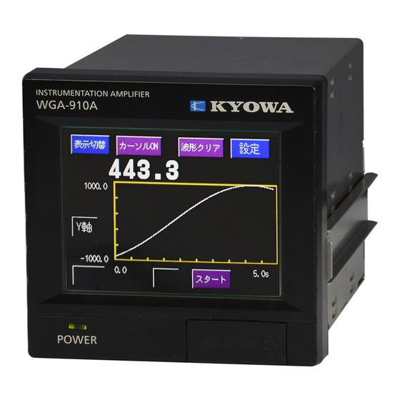
INSTRUMENTATION AMPLIFIER
Thank you for purchasing KYOWA's product WGA-910A Instrumentation
Amplifier.
Read this Instruction Manual carefully in order to make full use of the high
performance capabilities of the product.
Do not use the product in methods other than described in this Manual.
INSTRUCTION MANUAL
IM-A-1140 Oct 2017
WGA-910A
Advertisement

Subscribe to Our Youtube Channel
Related Manuals for KYOWA WGA-910A Series


Summary of Contents for KYOWA WGA-910A Series
- Page 1 Generally, company names and trade names described in this Instruction Manual are trademarks or registered trademarks of the companies. This Instruction Manual may not be copied or reproduced, in whole or part, without consent of KYOWA. Copyright © Kyowa Electronic Instruments Co., Ltd. All rights reserved.
- Page 2 CONTENTS STANDARD ACCESSORIES ···········································································································1 OPTIONS ····································································································································1 SAFETY PRECAUTIONS ···············································································································2 PRECAUTIONS ON CE MARKING··································································································5 NOTATIONS USED IN THE INSTRUCTION MANUAL········································································6 IMPORTANT PRECAUTIONS WHEN USING WGA-910A ····································································6 1. OUTLINE OF PRODUCT ············································································································7 1-1. OUTLINE ···························································································································7 1-2. FEATURES ·························································································································7 1-3. MODEL ······························································································································8 2. CONTROLS AND FUNCTIONS ····································································································9 2-1.
- Page 3 6-2-2. Zero Compensation ········································································································ 57 6-2-3. Additional Value ············································································································ 58 6-2-4. Sensor Output Value (Original Value) ················································································· 59 6-3. MEAS. COND. SETTING (SETTING MEASURING CONDITION) ··············································· 60 6-3-1. Measuring Condition ······································································································ 60 6-3-2. Comparison Setting ········································································································ 61 6-3-3. Measure Mode Setting····································································································· 65 6-3-4.
- Page 4 11. SPECIFICATIONS ·················································································································138 11-1. WGA-910A (WGA-910A-0) ·································································································138 11-2. DIMENSIONS··················································································································141 12. APPENDIX ···························································································································142 12-1 LIST OF SETTING ITEM ···································································································142 12-1-1. Calibration ················································································································142 12-1-2. Input Setting ··············································································································142 12-1-3. Measuring Condition Setting ··························································································143 12-1-4. Waveform Display Setting ·····························································································143 12-1-5. Initial Setting··············································································································144 12-1-6. Option Setting ············································································································145 12-2.
- Page 5 Test Data Sheet and Warranty 1 each *1. Including a PC software for a SD card. OPTIONS Model Manufacture AC power cable (100-VAC) P-23 KYOWA ELECTORONIC INSTRUMENTS CO., LTD. AC power cable (200-VAC) P-28 KYOWA ELECTORONIC INSTRUMENTS CO., LTD. INPUT connector PRC03-12A10-7M10.5 TAJIMI ELECTRONICS CO., LTD...
- Page 6 (hereinafter referred to as the WGA-910A). For safe use of the WGA-910A, do not forget to read the “Safety Precautions” prior to use. Kyowa Electronic Instruments Co., Ltd. assumes no liability for any damages resulting from user’s failure to comply with the safety precautions.
- Page 7 WGA-910A to the measuring object and external devices, PC, etc. Fuse Used for preventing a fire hazard. If you want to replace fuses, contact KYOWA or our representatives. Inflammable Gaseous Environment To prevent fire and explosion hazards, do not operate the WGA-910A where it is exposed to inflammable gases, inflammable vapors or inflammable dust.
- Page 8 CAUTION Caution Be sure to observe the safety precautions described in the WGA-910A Instruction Manual. Do not use the product outdoors. Or, it may cause electric shock, fire hazard, lower the performance and cause troubles. Do not turn ON the power switch immediately after turning it OFF. After turning OFF the power switch, wait (5 seconds) until the power supply is shut OFF before turning ON the power switch again.
- Page 9 CAUTION SD cards The capacity of the SDHC card, applicable to the product, is up to 32 GB. The product does not support the SDXC cards 64 GB or more. Never insert the SDXC cards 64 GB or more. PRECAUTIONS ON CE MARKING NOTE Be sure to mount the product on the control panel, etc.
- Page 10 NOTATIONS USED IN THE INSTRUCTION MANUAL The following notations are used in the Instruction Manual for convenience. Names described on the panel surface Names described on the panel surface are expressed in double quotation mark " ". Informational notes Certain notations are used as necessary to attract your attention to information that requires special care when handing the product, and to information provided for reference purposes.
- Page 11 1. OUTLINE OF PRODUCT 1-1. OUTLINE The WGA-910A Instrumentation Amplifier (hereinafter referred to as the WGA-910A) is a high-speed and sophisticated amplifier designed to be used for displaying physical quantities (load, etc.) with strain gage transducers. The WGA-910A is able to be operated from the front touch panel. The WGA-910A includes various functions (comparator functions, hold functions, etc.) as standard equipment.
-
Page 12: Table Of Contents
1-3. MODEL The WGA-910A series has 6 models including the optional units. Customers are required to purchase the products applicable to you. The number of channels, Model Option input format WGA-910A-0 None WGA-910A-1 WGA-910A-2 Load (strain) WGA-910A-3 RS-485 WGA-910A-4 CC-Link WGA-910A-12 BCD・D/A... - Page 13 2. CONTROLS AND FUNCTIONS 2-1. FRONT PANEL 2-1-1. Measuring Window (Number) Switch Hold Zero Detecting Measure 1 Holding Time Peak 999.99 500.00 - 150.00 - 999.99 Hold key Manually starts a detection and holding. Switch key Display changes in order from “Number” - “Zoom in number” - “Waveform” by pressing the key.
- Page 14 2-1-2. MeasuringWindow(ZoomInNumberforotherthanthe[BlockPeak-Bottom]and[TimePeak-Bottom]) Switch Zero Switch key Display changes in order from “Number” - “Zoom in number” - “Waveform” by pressing the Switch key. Comparator status lamp When turning ON the comparator outputs, the [HH] and [HI] light up in red, [OK] lights up in white, and [LO] and [LL] light up in yellow.
- Page 15 2-1-3. Measuring Window (Waveform for other than the [Block Peak-Bottom] and [Time Peak-Bottom]) Switch Cursor ON Wave Clear 300.00 Y-axis -200.00 10.0 RECORD X-axis Start Cursor ON key The “Cursor” window appears to display a cursor. Switch key Display changes in order from “Number” - “Zoom in number” - “Waveform” by pressing the Switch key.
- Page 16 2-1-4. Measuring Window (Cursor) Switch Cursor OFF Detect Move 300.00 -200.00 10.0 Cursor Cursor OFF key The cursor disappears and gets back to the “Waveform display” window. Switch key The Switch key is displayed in gray and no key operation can be performed. Measured value Displaying a measurement waveform data (value of the Y-axis) at the yellow point on the cursor.
- Page 17 2-1-5. Measuring Window (Number View Dual Display for [Block Peak-Bottom] and [Time Peak-Bottom]) Switch Hold Zero Detecting Holding Block Peak-Bottom Measure 1 Peak HI-1 500.00 LO-1 -999.99 Bottom HI-2 500.00 LO-2 -999.99 Hold key Manually starts a detection and holding. Switch key Display changes in order from “Number View Dual Display”...
- Page 18 2-1-6.MeasuringWindow(ZoomInNumberViewDualDisplayfor[BlockPeak-Bottom]and[TimePeak-Bottom]) Switch Zero Peak Bottom Switch key Display changes in order from “Number View Dual Display” - “Zoom In Number View Dual Display” - “Waveform View Dual Display” by pressing the Switch key. Comparator status lamp for Based on the detecting peak value, when turning ON the comparator outputs, peak value the [HI-1] light up in red, [OK] lights up in white, and [LO-1] lights up in yellow.
- Page 19 2-1-7.MeasuringWindow(WaveformViewDualDisplayfor[BlockPeak-Bottom]and[TimePeak-Bottom]) Switch Cursor ON Wave Clear Peak Bottom 903.17 -245.68 300.00 Y-axis -200.00 10.0 RECORD X-axis Start Cursor ON key The “Cursor” window appears to display a cursor. Switch key Display changes in order from “Number View Dual Display” - “Zoom In Number View Dual Display”...
- Page 20 Manufacture: TAJIMI ELECTRONICS CO., LTD. Pin No. Signal Name +BV (Red) -SIG (White) -BV (Black) +SIG (Green) Shield TEDS (+) (Yellow) TEDS (-) (Blue) Connector pin assignment of the WGA-910A MEMO Cable colors described the above are KYOWA’s standard color codes.
- Page 21 Connector for RS-232C Sends and receives data such as measuring data, setting value, etc with the RS- 232C. Applicable connector Jack: FCN-361J008-AU FUJITSU COMPONENT LINITED Cover: FCN-360C008-B FUJITSU COMPONENT LINITED Pin No. Signal Name Connector pin assignment of the WGA-910A Protective grounding terminal To prevent an electronic shock hazard, be sure to ground the terminal.
- Page 22 Control I/O connector Connection I/O terminal for controlling. Signal type of the control input is non voltage connection signal or open collector signal. Output type of the control output is open collector. Applicable connector Connector model: PCR-S36FS+ Manufacture: HONDA TSUSHIN KOGYO CO., LTD. Case model: PCR-LS36LA Manufacture:...
- Page 23 3. CONNECTION 3-1. PROCEDURES FOR MEASUREMENTS This section describes necessary operations to be conducted prior to the actual measurements. Section 3-2 To mount the WGA-910A Mount the WGA-910A on the panel. on the panel ↓ Section 3-3-1 To connect transducers Connect various transducers to the WGA-910A.
- Page 24 3-2. INSTALLATION ONTO A PANEL To install the WGA-910A to a panel, prepare the panel according to the specified panel cut dimensions shown at the right. Then, install the WGA-910A by referring to the following instructions. 1) Cut out the panel according to the panel cut dimensions. 2) Remove screws of the fitting metals attached on both sides of the WGA-910A and then, pull out the fitting metals.
- Page 25 3-3-1. Connecting transducer ・Input connector is NDIS one-touch connector. ・When using a KYOWA’s transducer with the NDIS standard connector at the tip of the cable, the both TEDS- compatible and non-TEDS-compatible sensors (excluding six-wire system remote sensing) can be directly connected to an input connector ・When using the KYOWA’s sensor without a connector at the tip of the cable or when using other manufactures...
-
Page 26: Model
3-3-2. Connecting Control Input ・Applicable connector of the cable side is as follows. Connector PCR-S36FS+ Manufacture: HONDA TSUSHIN KOGYO CO., LTD. model: Case model: PCR-LS36LA Manufacture: HONDA TSUSHIN KOGYO CO., LTD. ・Pin numbers and signal names of the control input are as follows. Pin No. - Page 27 3-3-3. Connecting Control Output ・The control output signal is open collector output and sink type. ・Applicable connector of the cable side is as same as that of the control input side. ・Pin numbers and signal names of the control output are as follows. Pin No.
-
Page 28: Wga-910A-0
3-3-4. Connecting RS-232C Interface ・Applicable connector of the cable side is as follows. Jack: FCN-361J008-AU Manufacture: FUJITSU COMPONENT LIMITED Cover: FCN-360C008-B Manufacture: FUJITSU COMPONENT LIMITED ・Pin numbers and signal names are described as follows. Pin No. Signal Name ・Use a commercially available RS-232C/USB conversion adapter, etc. when there is no COM port for the RS-232C is attached to your PC. - Page 29 3-3-5. Monitior Output ・A voltage output is available on the terminal board provided on the amplifier’s rear. ・Outputs approx. ±5 V / ±3.2 mV. ・Use this voltage output to perform initial balancing, maintenance and inspection as well as operational testing. ・It also lets you to review measured waveform on an oscilloscope.
- Page 30 3-3-6. Connecting AC Power ■Connecting terminal block for AC power ・It is recommended to attach insulating coated press-fit terminals to the connecting wires. Use a press-fit terminal for copper wire (JIS C 2805 1.25-3) or equivalent. ・Remove a cover from the terminal board. ・Before connecting the solderless terminals and power cable, remove screws as described in the right figure.
- Page 31 Checking power voltage NOTE Before connecting the power cable to the AC outlet, check the power voltage. The operating power voltage of the WGA-910A is from 100 to 240 VAC, 50/60 Hz, 20 VA or less. Be sure to keep this operating power voltage. If the power voltage exceeds the above specified voltage range or if the power voltage terminal has potential with excessive power voltage against the ground, no connection is made and it may cause trouble or damage to the WGA-910A.
- Page 32 3-4. SD Card ・Capable of updating a setting value of the WGA-910A by reading the setting value that is saved in the SD card. ・Capable of saving the setting value of the WGA-910A in the SD card. ・Capable of saving a recorded waveform in the SD card by pressing the Start key on the “Waveform” window. NOTE 1 Capacity of the SDHC card corresponding to the WGA-910A is up to “32 GB.”...
- Page 33 4. BASIC OPERATION PROCEDURES 4-1. SETTING TREE Measuring Window Measuring Window Measuring Window Number Zoom in Number Waveform (Number View Dual (Zoom in Number (Waveform View Dual Display) Display) View Dual Display) Setting Waveform and cursor Calibration Manual Input Cal. TEDS Auto Cal.
- Page 34 Wave Display Setting Y-axis Setting X-axis Setting Start Mode of Wave X-axis End P. Y-axis Start P. Y-axis End P. Passed Level Level Passed Way Hold Time of Wave Initial Setting Meas. Select Signal System Self-Check <1/2 page> Memory Check Key Lock Channel Check Set Initialize...
- Page 35 4-2. CONFIGURING WINDOWS *The previous turned OFF window is displayed when turning ON the WGA-910A. < Other than the [Block Peak-Bottom] and [Time Peak-Bottom]> Switch Cursor ON Wave Clear 300.00 Y-axis -200.00 10.0 RECORD X-axis Start <[Block Peak-Bottom] and [Time Peak-Bottom]> Switch Cursor ON Wave Clear...
- Page 36 4-3. BASIC OPERATION OF SETTING Setting windows appear as follows. 1) Press the key on the “Measuring” window. 2) Press the target main item key on the “Setting” window. Main item key 3) Press the target item key on the main item window. Calibration Return Measure...
- Page 37 4-4. HOW TO OPERATE WAVEFORM AND CURSOR WINDOWS “Waveform” window Press the key. Displaying waveform starts when conditions which were set in the “Waveform” window are satisfied. After pressing the key, the key changes to the key. Press the key to stop loading the waveform data.
- Page 38 X axis is 0.5 s, 1.0 s, 2.0 s: Since the WGA-910A prioritizes the writing process than the saving process, the WGA-910A does not save waveform data continuously when changing windows. 3) The waveform data is saved with the following file name and the newly created file is KYOWA original format.WGA_910A_Dxxxxx.KS (xxx : 00001~21844) 4) New waveform file is not created when the all waveform files (No.
- Page 39 “Cursor” window While stopping the loading of the waveform, press the key to display the “Cursor” window. The cursor moves directly to the Gets back to the “Waveform” Detecting point. When detecting the both peak value and bottom value, as you press the Displays the data of the Y-axis key, the detecting point changes as (measured value) at the yellow...
- Page 40 5. CALIBRATION 5-1. OUTLINE OF CALIBRATION The WGA-910A has 4 calibration methods; manual input calibration, TEDS-based automatic calibration, partial calibration based on TEDS calibration data, and numeric value registering calibration. Manual input calibration: Enters the calibration data manually. The manual input calibration includes the "Sensitivity registering calibration" that calibrates data by registering a sensitivity value written in the test data sheet of transducers and "Actual load calibration"...
- Page 41 5-2. PROCEDURES OF CALIBRATION Measuring Window Setting Window Calibration Window Manual Input TEDS-based Partial Calibration Numeric Regist Cal. Calibration Automatic based on TEDS Calibration Calibration Data Manual Input Cal. TEDS TEDS Numeric Auto Part Regist Cal. Bridge Voltage TEDS Auto Cal. No-load ZERO TEDS Part Cal.
- Page 42 5-3. HOW TO CALIBRATE 5-3-1. Calibration Window <How to operate> 1) Press the key on the “Measuring” window. 2) Press the key on the “Setting” window. 5-3-2. Manual Input Calibration Conducts calibration by manual setting in order of excitation voltage, no-load zero, Sensitivity registering calibration or in order of actual load calibration and unit.
- Page 43 (2) No-Load ZERO Loads the output voltage of the sensor with no-load applied and registers it as a reference of a total zero. No-load zero adjustment range is same with the measuring range. <Setting range> (-3.2000 to +3.2000 mV/V; display only) <How to operate>...
- Page 44 (3-a) Sensitivity Regist. Cal. (Sensitivity Registering Calibration) Inputs the rated capacity and rated output described in the Test Data Sheet for equivalent calibration with the actual load when the actual load cannot be applied to the sensor. Suppose that you are using a transducer with the “Rated Capacity: 200 kN”...
- Page 45 (3-b) Actual Load Cal. (Actual Load Calibration) Actual load is applied to the sensor for the calibration. Displays the output when an actual load is applied as the rated output. Suppose that you are using a transducer with the “Rated Capacity: 200 kN” and “Rated Output: 2.0040 mV/V.”...
- Page 46 (4) Unit Set the target unit. Refer to “11-2 UNIT LIST” for available unit. In order to display “kgf,” do as follows. <Setting range> Refer to “11-2 UNIT LIST.” <How to operate> 1) Select the type of the unit first and press the target key. Press the key as an example.
- Page 47 5-3-3. TEDS Auto Cal. (TEDS-based Automatic Calibration) The calibration is automatically conducted by reading the required information for the calibration (applied voltage, rated output, and unit) from the TEDS built-in sensor and the calibration data that is saved inside is overwritten. However, the “TEDS-based Automatic Calibration”...
- Page 48 NOTE “TEDS Error” window blinks when the TEDS information cannot read correctly or TEDS information value is out of specifications. After stopping the reading of the TEDS information, the “TEDS Error” window blinks approx. 3 seconds. After that, the current calibration value is displayed. At this time, the calibration value is not updated.
- Page 49 5-3-4. TEDS Part Cal. (Partial Calibration Based on TEDS Calibration Data) Only the selected information from the TEDS built-in sensor (select one or multiples from the applied voltage, rated display, rated output, unit) is updated the calibration data that was saved internally and calibrated automatically. However, the “Partial Calibration Based on TEDS Calibration Data”...
- Page 50 6) The calibration starts and the “TEDS Calibration” window on the upper left blinks. Blink 7) The calibration finishes after a short time and a new calibration value is displayed on the “New” column. Press the key at last to get back to the “Measuring” window. NOTE “TEDS Error”...
- Page 51 5-3-5. Numeric Value Registering Calibration The numeric value registering calibration calibrates data by changing the initial value. Execute the numeric value registering calibration after the actual load calibration and sensitivity registering calibration. The numeric value registering calibration is used for pressure transducers for absolute pressure measurement or when already load is applied and unable to obtain the actual load state.
- Page 52 MEMO When executing the numeric value registering calibration with communication during measurements or settings, the 【Registering ini. val.】 window blinks Registering Registering Switch Hold Zero Measure ini. val. ini. Val. Calibration is conducted with Detecting Measure 0 Calibration sensor by 'Manual Input','TEDS Auto'or'TEDS Part'Cal.
- Page 53 6. OPERATION AND FUNCTION 6-1. CALIBRATION For the “Manual Input Calibration,” “TEDS-based Automatic Calibration,” and “Partial Calibration Based on TEDS Calibration Data,” refer to “5. CALIBRATION.” This chapter describes how to operate the digital zero function on the “Measuring” window and how to set for the TEDS operation.
- Page 54 (2) By the control input operation from the rear panel 1) To execute the digital zero once, short-circuit the 35 (or 36, input COM) and 19 (ZERO command) on the control I/O connector located on the back panel. 2) Capable of conducting while the setting is locked. 3) To execute the digital zero again, open the 35 (or 36, input COM) and 19 (ZERO command) on the control I/O connector located on the back panel and short-circuit them again.
- Page 55 4) Press the key on the “TEDS Ope. Setting” window. 5) Every time the right key of the target item is pressed, key appears alternately. After setting every reading operation item, press the key. (2) ZERO during TEDS Capable of selecting whether conduct or prohibit the no-load zero at the same time when reading the TEDS information for the calibration.
- Page 56 Rated Output (combined): Average value of the rated outputs of the sensors (Value obtained by dividing the total value of sensors with the number of units.). (7) Model, serial No., and calibrated date of the TEDS For reading the KYOWA made sensor only. The information may not be read when connecting the other made TEDS-compatible sensor.
- Page 57 (8) When displaying error. During the TEDS calibration, due to the following causes, the TEDS information cannot be read, displays the “TEDS Error” and sensitivity registering may not be conducted. ・TEDS signal lines are wrongly connected. Check the wiring by referring to “3-2 WIRING.” ・The connecting number of sensors is not applicable.
- Page 58 6-2. INPUT SETTING 6-2-1. Smoothing Smoothing is a function whereby fluctuations of the display values are made stable by eliminating unnecessary noise component. Though the most popular noise at the site is a hum noise due to the AC power, noise due to the motor in the control system also generates frequently.
- Page 59 (2) Minimum Scale (division) Sets the minimum digit that changes the number. However, the minimum scale not only suppresses the variation of the display value but also not to update the display value higher than the requiring resolution. Displays the setting values of the minimum scale according to the preset decimal position that was set in the rated display of the calibration.
- Page 60 (3) Moving Average Conducts the moving average for the preset times for filtering. <Setting value> None, 2, 4, 8, 16, 32, 64, 128, 256, 512, 1024, and 2048 times <How to operate> 1) Press the key on the “Smoothing” window. 2) Press the key to change pages until the target value is displayed.
- Page 61 6-2-2. Zero Compensation Automatically corrects subtle zero point drifts. It effectively reduces measurement error inducible to zero drifts on a sensor or on the WGA-910A as well as zero drifts caused by deposits on a measuring object. (1) ZERO every Comp. Time (Zero Tracking) Conducts digital zero and automatically sets the display value to “0”...
- Page 62 (2) Min. Scale Zero Fix (Zero around zero) Means least significant digit fixed at zero. Automatically sets the display number of the least significant digit (the rightmost digit) to “0” when the measuring value is within the setting range of + and - directions. The Min.
- Page 63 6-2-4. Sensor Output Value (Original Value) Displays the current output value of the sensor on the monitor. After pressing the key, the output value is measured for every 0.5 second and displayed in both units “mV/V” and “με.” <Setting Range> -3.2000 to 3.2000 (mV/V) (-6400.0 to 6400.0 με) <How to operate>...
- Page 64 6-3. MEAS. COND. SETTING (SETTING MEASURING CONDITION) Capable of storing setting values of the comparison setting and measuring mode setting to the measuring condition file and capable of changing the measuring condition No. by the key operation, control input, or communication command. The number of the measuring condition files is 32 for the key operation, 16 for the control input, and 32 for the communication command.
- Page 65 Switching the measurement conditions with the control input. For the “Control Input” on the “Meas. Select Signal” window only. Switch the ON/OFF of the control input’s “Measurement condition select 0 to 3” as the following table. Measuring Measurement Measurement Measurement Measurement Condition Condition Select 0...
- Page 66 <Direct operations from the “Measuring” window> 1) Press any of the key on the “Measuring” window. 2) The window changes to the setting window of the target compared values. Input a setting value with the numeric keyboard and press the key for registering.
- Page 67 (3) Comparator Out. Logic Common to all comparators. Sets the output logic (open collector logic) of comparators. <Setting Range> Negative Logic Comparator output is ON when the comparison result is ON. (Active low) Positive Logic Comparator output is OFF when the comparison result is OFF. (Active high) <How to operate>...
- Page 68 Displayed in gray Displayed in gray (5) Relation between the comparator outputs and hysteresis width and behaviors of comparator status lamps. HH comparator (or HI1 comparator) When the measured value exceeds the HH compared value, the HH comparator output is turned ON and [HH] lamp lights up in red. When the measured value lowers the (HH compared value - hysteresis width), the HH comparator output is turned OFF and [HH]...
- Page 69 6-3-3. Measure Mode Setting Capable of setting various operating modes of the measurement. In addition, capable of setting the display mode and comparison mode. The measurement is controlled by the key and control inputs operations. In addition, operation statuses can be checked with the comparator status lamps on the “Measuring” window as follows.
- Page 70 Block (-specified) Indicates the average value of measured values by the block-specified operation. When average the HOLD command is turned OFF, the indicated average value is kept hold. When the (measurement) RESET command is turned ON, the indicated average value is canceled. Time(-specified) Indicates the average value of measured values by the time-specified operation.
- Page 71 (2) Detect Time Sets a time of the detecting block. For the “Time-specified Peak", “Time-specified Bottom”, “Time Peak-Bottom", and “Time Averaging" in the “Operation Mode” window only. For other operation modes, setting of the “Detect time” is invalid. <Setting Range> 0.00 to 9.99 (sec) <How to operate>...
- Page 72 (4) Comparison Mode Selects the operation block of the comparators from the two modes. Sets the target Comparison Mode. For the “Block-specified Peak", “Block-specified Bottom”, “Time-specified Peak ", “Time-specified Bottom", “Block Averaging” and “Time Averaging" in the "Operation Mode" window only.
- Page 73 (5) Display Mode Selects the display operation of the peak (bottom) value from the two modes. Sets the target Display Mode. For the “Block-specified Peak", “Block-specified Bottom”, “Time-specified Peak ", “Time-specified Bottom", “Block Averaging” and “Time Averaging" in the "Operation Mode" window only. For other operation modes, “Display Mode"...
- Page 74 6-3-4. Descriptions of the operation mode 6-3-4-1. Normal Normal measurement that always measures and displays value. No control signal for the detection. “Detect Time”, “Delay Time”, “Comparison Mode”, “Display Mode” cannot be set. 6-3-4-2. Peak Hold Capable of setting the “Delay time.” However, the “Detect Time”, “Comparison Mode”, and “Display Mode” cannot be set. (A) Behavior with control input signal When the HOLD command is turned ON and after the lapse of delay time, the peak...
- Page 75 6-3-4-3. Block-specified peak and block-specified bottom Capable of setting the “Delay time”, “Comparison Mode”, and “Display Mode.” However, the “Detect Time” cannot be set. (1) Normal Display Mode (A) Behavior with control input signal When the HOLD command is turned ON and after the lapse of delay time, the peak (bottom) value is detected until the command is turned OFF.
- Page 76 6-3-4-4. Time-specified peak and time-specified bottom Capable of setting the “Detect Time”, “Delay time”, “Comparison Mode”, and “Display Mode.” (1) Normal Display Mode (A) Behavior with control input signal When the HOLD command is turned ON and after the lapse of delay time, the peak (bottom) value is detected and indicated for the preset detection time.
- Page 77 6-3-4-5. Bottom Hold Capable of setting the “Delay Time.” However, the “Detect Time”, “Comparison Mode”, and “Display Mode” cannot be set. (A) Behavior with control input signal When the HOLD command is turned ON and after the lapse of delay time, the bottom value is detected and indicated until the HOLD command is turned OFF.
- Page 78 6-3-4-7. Block Peak-Bottom and Time Peak-Bottom 1) Block Peak-Bottom/Normal display mode “Detect Time”, “Delay Time”, “Comparison Mode”, “Display Mode” can be set. However, the “Detect Time” cannot be set. (A)Behavior with control input signal When the HOLD command is turned ON and after the lapse of delay time, the peak value and bottom value are detected and indicated until the HOLD command is...
- Page 79 6-3-4-8. BlockAveraging and Time Averaging (1) Block averaging/Normal display mode “Delay Time”, “Comparison Mode”, and “Display Mode” can be set. However, the “Detect Time” cannot be set. (A) Behavior with control input signal When the HOLD command is turned ON and after the lapse of delay time, the average value is detected and indicated until the Hold command is turned OFF.
- Page 80 (2) Time averaging/Hold display mode “Detect Time”, “Delay Time”, and “Comparison Mode” can be set. (A) Behavior with control input signal When the HOLD command is turned ON and after the lapse of delay time, the average value is detected. However, during the delay time and detecting block, the measured value that is detected immediately after turning ON the Hold command is displayed.
- Page 81 6-3-5. How WGA-910A works with HOLD and RESET commands The WGA-910A works as follow during detecting, holding, and normal blocks by turning ON/OFF the “HOLD command” and “RESET command.” [Example] Block-specified peak...
- Page 82 6-3-6. Relations Between Control Inputs, Comparator Outputs, and Operation Statuses for [Block Peak- Bottom] and [Time Peak-Bottom] (Example) [Block Peak-Bottom] NOTE For the [Block Peak-Bottom] and [Time Peak-Bottom]: When the measured value is within the HI-1 and LO-1 of the Peak Value or within the HI-2 and LO-2 of the Bottom Value, the OK lamp on the target window lights up in white.
- Page 83 6-4. WAVE DISPLAY SETTING (SETTING WAVEFORM DISPLAY) 6-4-1. Setting X-axis Sets the end point of the time axis (= X-axis of the waveform). Displays the waveform from the start (press the key on the “Waveform” window) to the preset time of the X-axis end point as one window.
- Page 84 <The number of the waveform data in one window> MEMO The number of the waveform data in one window is 2001 data (including the data at the 0.0 sec.). The averaging value data that is sampled during the interval in the following table is loaded as a waveform data when the X-axis is set other than “0.5 sec.”...
- Page 85 6-4-2. Setting Y-axis Sets the start point and end point of the measured value (= Y-axis of the waveform). Press the key on the “Waveform” window. The “Y-axis Setting” window appears directly. <Setting Range> Start point: -99999 to 99999 (count, Decimal point and unit should be considered.) End point: 250, 500, 1000, 2000, 5000, 10000, 20000, 50000, 100000, 200000 (count, Decimal point and unit should be considered.)
- Page 86 6-4-3. Start Mode of Wave (Trigger Mode) Sets a start mode (trigger mode) for displaying the waveform. Operations of modes are described as follows. <Setting Range> Auto Mode, Normal Mode, Single Mode Wave Display Setting <How to operate> Return Measure The end point of X-axis(time) 1) Press the key on the “Wave Display Setting (1/2)”...
- Page 87 (3) Single Mode Press the key or turn ON and OFF (MIN interval: 1 ms) the “Waveform Command” to set the WGA- 910A in the trigger condition waiting mode. After that, the WGA-910A starts displaying the waveform when the measured value satisfies the trigger condition.
- Page 88 6-4-5. Level Passed Way (Trigger Slope) Sets the way that the measured value passes the “Passed Level” as a trigger condition. Passes from the lower level of the Passed Level to higher level. ・Rising: ・Falling : Passes from the higher level of the Passed Level to lower level. Passes from the higher level of the Passed Level to lower level and from the lower level of the Passed ・Both: Level to higher level.
- Page 89 6-5. INITIAL SETTING 6-5-1. Meas. Select Signal (Measuring Condition Selecting Signal) Sets a signal for selecting a measuring condition number. ・For key operation: Sets the measuring condition No. by pressing key on the “Meas. Cond. Setting” window. ・For control input: Sets the measuring condition No.
- Page 90 6-5-2. System (1) Key Lock Select lock (inhabit changing) or release. key is invalid and displayed in gray in locked state. key changes to the key after the window gets back to the “Measuring” window. Press the key with the locked state. The window changes to the “Key Lock” window to release the locked state.
- Page 91 (2) Set Initialize Initializes the saved setting value to the default value. However, the calibration value is not initialized. <Setting Range> Input Set: Initializes setting values of the input setting. Meas. Cond. Set: Initializes setting values of the measuring condition setting. Wave Disp.
- Page 92 (3) Backlight Time Sets a lighting time of the backlight. The backlight goes off if you don’t touch the panel for the preset time. Touch the panel for lighting up. <Setting Range> 0 to 99 (minute) <How to operate> 1) Press the key on the “System (1/2)”...
- Page 93 (5) Clock Adjusts date and time of the built-in clock. <Setting Range> Year, Month, Day, Hour, Minute, Second (2000/01/01 00:00:00~2099/12/31 23:59:59) <How to operate> 1) Press the key on the “System (2/2)” window. System Return Measure The time of built-in clock is Clock set.
- Page 94 6-5-3. Self-Check Self diagnosis the WGA-910A and sensor input. In addition, the program version and serial No. can be checked on the “Self-Check” window. (1) Memory Check Checks that the ROM, RAM, and EEPROM have no fault. Press the key to start the memory check. The result is displayed after a short time. When an error occurs, the WGA-910A turns ON the control output “Abnormal memory.”...
- Page 95 (2) Channel Check Checks the operation related to the sensor input. Press the key to start the channel check. The result is displayed after a short time. When an error occurs, the WGA-910A turns ON the control output “Abnormal channel.” <Setting Range>...
- Page 96 6-5-4. Operation Check (1) Display Check Checks the display operation. Check items are moved as follows. <Setting Range> Color: Window color automatically changes from Red - Green - Blue - Yellow - Red by pressing the key. Backlight: Press the key to go off the backlight.
- Page 97 (2) Touch Panel Check For checking the touch panel operation. <How to operate> 1) Press the key on the “Operation Check (1/2)” window. 2) Press a white key on the window to change in yellow. Press the yellow key again to get back to white. Press the key to get back to the “Operation Check”...
- Page 98 (4) Communication Check Checks that RS-232C and RS-485 correctly sends and receives information. When an error occurs, the WGA-910A turns ON the control output “Communication error.” Press the key to transfer data “WGA-910A” that is displayed on the transferring data column. The transferred data from the external device is displayed on the received data column.
- Page 99 (6) D/A Output Check Valid for equipping the optional D/A output (WGA-910A-2) or BCD and D/A output (WGA-910A-12). Capable of checking the operation of the connecting external device by outputting an arbitrary D/A converted voltage. key is displayed in gray when the optional D/A output board is not connected. <Setting Range>...
- Page 100 (7) SD Card Check Checks the SD card operation and displays it if any error is detected. MEMO The control output [SD] is turned ON while accessing to the SD card. <How to operate> 1) Press the key on the “Operation Check (1/2)” window.
- Page 101 NOTE 1 Do not remove the SD card until you have received a result during checking. Or, it may cause damage or may disrupt the WGA-910A operation. NOTE 2 If the SD Card Check is conducted with many files or large capacity file saved in the SD card, the “Checking SD card”...
- Page 102 6-5-5. SD CARD SETTING (1) Set Value Save (Saving Setting Value) Capable of saving the all setting values of the WGA-910A to the SD card and capable of checking them with the PC software for the SD card. The control output [SD] is turned ON while saving the setting values. Initial Setting Return Measure...
- Page 103 (2) Set Value Read (Reading Setting Value) After writing the edited setting value with the PC software for the SD card to the SD card, insert the SD card to the WGA-910A for reading. And the setting values of the WGA-910A are rewritten. The control output [SD] is turned ON during reading the setting values.
- Page 104 About writing/reading the setting value to the SD card and reading the waveform data Capable of writing the setting value to the SD card and capable of reading the setting value and waveform data from the SD card with the PC software for the SD card. Capable of converting the waveform data to the CSV file and displaying the waveform.
- Page 105 (3) View Wave File Name This section describes how to display the waveform file name saved in the SD card and delete waveform files. The WGA-910A saves the waveform files in date-based directories. You are able to delete the date-based directories. You are able to delete single waveform file, multiple waveform files, and all waveform files.
- Page 106 <To select/cancel the directory> View Wave File Name Return Measure 1) Select the page by the key. Next Previous Directory Directory Select the directory by the key for highlighting 20160330 20160324 20160310 (background color: white, character color: black). 20160306 One Select 20160303 20160301 20160228...
- Page 107 <To select/cancel all waveform files> View Wave File Name Return Measure Name Size Renewal Date Data Select 1) To select all waveform files, press the key. 00200 12.0KB 22:59:59 All Select 00199 12.0KB 22:30:12 00120 12.0KB 21:00:00 The “Name”, “Size”, and “Renewal Date” of all waveform files of the 00119 12.0KB 20:40:33...
- Page 108 <To delete the directory> View Wave File Name Return Measure 1) Select the directory as described in the <To select/cancel the directory>. Directory Directory In the case of this example, the “20160202” is selected. 20160330 20160324 20160310 20160306 One Select 20160303 20160301 20160228...
- Page 109 (4) Format Erases (quick format) the all data saved in the SD card. SD Card Setting Return Measure <How to operate> The all set values excluding Set Value Save the calibration value are 1) Press the key on the “SD Card Setting (1/2)” saved to SD card.
- Page 110 (5) Update Capable of updating the program version of the WGA-910A to the target version in the SD card. <How to operate> 1) Press the key on the “SD Card Setting (2/2)” SD Card Setting Return Measure window. The program version of WGA- Update 910A is updated to the same version in the SD card.
- Page 111 About program for updating 4 program names are as follows. PVER.h WGA910_A.BIN WGA910_B.BIN WGA910_C.BIN The file format is dedicated to the WGA-910A. NOTE ・Never change the file name. Or, you cannot update the program. ・Save the all 4 programs in the root directory (ex. ¥E Drive) of the SD card. Or, you cannot update the program.
- Page 112 7. OPERATION TIMING 7-1. CONTROL INPUT (HOLD COMMAND, RESET COMMAND, ZERO COMMAND) 7-1-1. Control Input...
- Page 113 7-1-2. Block-specified 7-1-3. Time-specified...
- Page 114 7-2. COMPARATOR OUTPUT 7-3. DELAY TIME BETWEEN INPUT AND OUTPUT Delay time between input - RS output: MAX 30 ms...
- Page 115 7-4. DISPLAYING WAVEFORMS AND OUTPUTTING SD SIGNAL WITH WAVEFORM COMMAND (CONTROL OUTPUT) AND RECORD KEY 7-4-1. Single Mode <Conditions> Measuring condition setting Operation mode: Normal Waveform display setting X-axis setting: 2.0 sec, Start Mode of Wave: Single mode NOTE ・You can obtain the typical values with the blank recommended SD card (refer to page 28). ・According to the followings, typical values of the T3 and T5 may change with the above values.
- Page 116 7-4-2. Auto Mode, Normal Mode [X-axis setting: 0.5 sec, 1.0 sec, 2.0 sec] <Conditions> Measuring condition setting Operation mode: Normal Waveform display setting X-axis setting: 2.0 sec, Start Mode of Wave: Auto Mode, Normal Mode NOTE ・You can obtain the typical values with the blank recommended SD card (refer to page 28). ・According to the followings, typical values of the T2, T5 and T7 may change with the above values.
- Page 117 [X-axis setting: 5.0 sec, 10.0 sec, 20.0 sec, 50.0 sec, 100.0 sec] <Conditions> Measuring condition setting Operation mode: Normal Waveform display setting X-axis setting: 5.0 sec, Start Mode of Wave: Auto Mode, Normal Mode NOTE ・You can obtain the typical values with the blank recommended SD card (refer to page 28). ・According to the followings, typical values of the T2, T5 and T7 may change with the above values.
- Page 118 8. RS-232C COMMUNICATION Various functions can be set as well as measured values can be read from external devices. NOTE The RS-232C of the standard equipment is invalid and the RS-485 is valid when equipping the optional RS-485. Other than above, the RS-232C is functioned. 8-1.
- Page 119 (2) LIST OF CONTROL COMMANDS Type Contents Command Page (1) Initialize (2) RS line test (3) Output model, etc Initial settings (4) Transmission mode setting (RS-232C only) (5) Command of saving the setting (saving the setting value to the internal memory) (6) Output the displayed value.
- Page 120 8-3. DETAILS OF CONTROL COMMANDS This section describes various control commands and parameters following after the commands. <CR> and <CR><LF> denote termination code. 8-3-1. Initial setting (1) [RES] Content: Initialize the setting value. Format: RESp<CR> Parameter: 0: Input setting 1: Measuring condition setting 2: Waveform display setting 3: Initial setting 4: Optional setting...
- Page 121 (4) [MOD] Content: Set the transmission mode. Format: MODpp<CR> Parameter: 00: Continuously outputs the measured value and status. 02: Outputs the display value and status only 1 time while holding. 10: Operation with the control command. Description and others This command becomes disabled with the power OFF. Power ON and it is in Mode 10 operation mode.
- Page 122 8-3-2. Reading (6) [GDT] Content : Output the displayed value. Format : GDT x <CR> Parameter For the [Block Peak-Bottom] and [Time Peak-Bottom] 0: Peak value (measured value 1) and bottom value (measured value 2) in order. 1: Peak value (measured value 1) 2: Bottom value (measured value 2) For the other operation modes 1: Current measuring value (measured value 1)
- Page 123 (7)[GST] Content: Read the status. Format: GST<CR> Parameter None Return value format: Sabcdefghi<CR><LF> Description and others: Return value abcdefghi denotes the status with ‘1’ or ‘0.’ Numeric ‘1’ is output in the following state. a: HH comparator is ON. b: HI comparator is ON. c: OK comparator is ON.
- Page 124 8-3-3. Executing (10) [HLD] Content: Hold command Format: HLD<CR> Parameter: None Return value format: ok<CR><LF> Description and others Relevant to the Hold key operation on the touch panel. For reference:Arbitrary point hold HLD <CR> Holding interval RST <CR> Peak hold HLD <CR>...
- Page 125 (13) [CK1] Content: Hold command Format: HLD<CR> Parameter: None Return value format: ok<CR><LF> (when in normal) The CPU FlashROM is error: E-01<CR><LF> The external FlashROM is error: E-02<CR><LF> The CPU SRAM is error: E-03<CR><LF> The external SRAM is error: E-04<CR><LF> The external EEPROM is error: E-05<CR><LF>...
- Page 126 8-3-4. Setting (17) [SBV] Content: Set the excitation voltage. Format: SBVa<CR> Parameter: 0: 2V 1: 10V Return value format: ok<CR><LF> Description and others Corresponding to the [/M] command. Reading command PRR012 Return value a<CR><LF> 0: 2V 1: 10V (18) [ZAD] Content: Conduct no-load zero.
- Page 127 (21) [VRC] To execute numeric value registering calibrations Content: VRC±x.xxxx<CR> Format: Parameter: ±x.xxxx Initial value of transducers: -3.2000 to 3.2000 (mV/V) Return value format: ok<CR><LF> E-00<CR><LF>(When an error occurs) Description and others The results of the command will be saved. Reading command: PRR011 Return value...
- Page 128 (24) [SZM] Content: Set the additional value. Format: SZM1, ±xxxxxx<CR> Parameter: ±xxxxx -99999 to 99999 (count) Indicated value with a decimal point. If the indicated value has no decimal point, it is filled with ‘0’ from the head. Return value format: ok<CR><LF>...
- Page 129 (26) [SCF] Content: Set the comparison setting. Format: SCFa, b, c, d, e, xxxxxx<CR> Parameter: a, b, c, d, e, xxxxx Hysteresis width: 0 to 9999 (count) Including a decimal point. Comparator output logic 0: Negative logic 1: Positive logic Using comparator LL 0: Use 1: Not use...
- Page 130 (28) [SMF] Content: Set the measuring mode setting. Format: SMFaa, b, c, x. xx, y. yy<CR> Parameter: aa, b, c, x. xx, y. yy Detect time: 0.00 to 9.99 (sec.) Delay time: 0.00 to 9.99 (sec) Comparison mode 0: Normal Comp. 1: Hold Comp.
- Page 131 (30) [SG2] Content: Set the waveform display setting 1 (start mode of wave, passed level, level passing way, hold time of wave) Format: SG2a, b, ±xxxxxx, yy. y <CR><LF> Parameter: a, b, ±xxxxxx, yy. y Hold time of wave: 0.0 to 99.9 (sec) Indicated value with a decimal point.
- Page 132 (33) [SLG] Content: Set the language Format: SLGa <CR> Parameter: 0: Japanese 1: English Return value format: ok<CR><LF> Description and others Corresponding to the [/M] command. Reading command PRR152 Return value language (34) [STM] Content: Set clock. Format: STM, uu, vv, ww, xx, yy, zz <CR> Parameter: uu, vv, ww, xx, yy, zz Second: 00 to 59...
- Page 133 (35) [OP1] Content: Set communication (RS-232C and RS-485) Format: OP1, a <CR> Parameter: OP1, a Data Rate 0: 2400 bps 1: 4800 bps 2: 9600 bps 3: 19200 bps Return value format: ok<CR><LF> Description and others Corresponding to the [/M] command. Reading command PRR100 Return value...
- Page 134 (37) [OP3] Content: Set the D/A output. Format: OP3, ±xxxxxx, ±yyyyyy, a<CR> Parameter: OP3, ±xxxxxx, ±yyyyyy, a D/A classification (*2) 0: Peak value 1: Bottom value Full display: -99999 to 99999 (count) ZERO display: -99999 to 99999 (count) Both values include a decimal point. If the indicated value has no decimal point, it is filled with ‘0s’...
- Page 135 8-4. OPERATION AND FUNCTION OF THE COM. SETTING (COMMUNICATION SETTING) (1) Communication Speed Sets the communication speed (baud rate) of the RS-232C and RS-485. <Setting Range> 2400, 4800, 9600, 19200 (bps) <How to operate> 1) Press the key on the “Measuring” window. Switch Hold Zero...
- Page 136 (2) Transmission Mode Sets the transmission mode of the communication such as the measured value, sending method of the status, operation by the command, etc. <Setting Range> Repeat Output Continuously outputs the measured value and status (such as the HH comparator is ON, etc). Output at Hold Outputs the measured value and status once during the holding time.
- Page 137 If all this fails to recover normal operation, contact KYOWA or our representatives. KYOWA may deny repairs when the WGA-910A has been damaged through improper usage (i.e. not confirming to guidelines described in this manual), or when the WGA-910A has been disassembled or modified by the user.
- Page 138 5) TEDS Error Displaying Stops the reading of the TEDS information. Content: Cause: The TEDS information may not be read correctly or the interface may not corresponding to the IEEE1451.4 Mixed Mode Transducer Interface Class 2. In addition, the transducer may be faulty, cable may be disconnected or may be incorrectly connected.
- Page 139 The “No-load Zero” blinks for 3 seconds. After that, the “Input Value + Over” blinks again if the input value is exceeding +3.2 mV/V. If all this fails to recover normal operation, contact KYOWA or our representatives. 9-3. DISPLAY VALUE OR MONITOR OUTPUT DOES NOT CHANGE The display value does not change and monitor output does not output.
- Page 140 9-6. LARGE NOISE Probable causes are as follows. Inductive Interference Induction noise may be generated if an instrument having large leakage flux is near the WGA-910A. The instrument is such as large motor, electrical transformer, ferroresonance type constant voltage device. In addition, the induction noise may be also generated if the instrument is far from the WGA-910A.
- Page 141 Maintenance service should be performed at the intervals specified below. (1) Calibration of apparatus An annual maintenance inspection is recommended to ensure the operation and measuring accuracy of the product. Must be returned to KYOWA for the scheduled maintenance inspection. (2) Replacement of limited life parts Item Content...
- Page 142 11. SPECIFICATIONS 11-1. WGA-910A (WGA-910A-0) Number of channel Applicable sensor Strain gage transducers (Connectable TEDS compatible sensor) Applicable bridge resistance 87.5 to 1000 Ω TEDS compatible Interface: Compatible with IEEE1451.4 Mixed Mode Transducer Interface Class 2 Applicable transducer: Should have the information according to IEEE template No.
- Page 143 condition file can be saved. Capable of switching by the key operation, control input, communication command. Comparator setting The number of points : 5 Type : extra high (HH), high (HI), OK, low (LO), extra low (LL). For [Interval peak/bottom] [Time peak/bottom] only, Peak value: max.
- Page 144 Stop bit : 1 Parity bit Odd number Flow control : Not compatible Setting contents : Communication speed : 2400, 4800, 9600 ,19200 bps Transmission mode : Repeat Output, Output at hold, Tx and Rx SD card Saving setting value : Saves the all setting value (excluding the calibration value) to the SD card Reading setting value : Reads the all setting value (excluding the calibration value) from the SD card and rewrite...
- Page 145 11-2. DIMENSIONS Unit:mm...
- Page 146 12. APPENDIX 12-1 LIST OF SETTING ITEM 12-1-1. Calibration Item Function Name Parameter Name Setting Value Initial Value Manual Input Cal. Bridge Voltage 0:2 V, 1:10 V No-Load Zero (-3.2000 to 3.2000 mV/V) (0.000 mV/V) Sens. Regist. Cal. Rated output -3.2000 to 3.2000 mV/V 2.0000 mV/V Rated display...
- Page 147 12-1-3. Measuring Condition Setting Item Function Name Parameter Name Setting Value Initial Value Meas. Cond. Setting 1 to 32 Comparison Setting HH compared value -99999 to 99999 99999 HI compared value -99999 to 99999 10000 LO compared value -99999 to 99999 -10000 LL compared value -99999 to 99999...
- Page 148 12-1-5. Initial Setting Item Function Name Parameter Name Setting Value Initial Value Meas. Select Signal 0: Key Operation, 1: Control Input,2: Command Operation Key Lock 0: Release, 1: Lock Release System Set Initialize 0: Input Set, 1: Meas. Cond. Set, 2: Wave Disp.
- Page 149 12-1-6. Option Setting Item Function Name Parameter Name Setting Value Initial Value Com. Setting Communication Speed 0: 2400 bps, 1: 4800 bps, 9600 bps 2: 9600 bps, 3: 19200 bps Transmission Mode 00: Repeat. Output, Tx and Rx 02: Output at Hold, 10: Tx and Rx CC-Link Setting Occupied Stations...
- Page 150 Kyowa Electronic Instruments Co., Ltd. 3-5-1, Chofugaoka, Chofu, Tokyo 182-8520 Japan http://www.kyowa-ei.com/...
Need help?
Do you have a question about the WGA-910A Series and is the answer not in the manual?
Questions and answers