KYOWA WGA-910A Series Instruction Manual
For cc-link option
Hide thumbs
Also See for WGA-910A Series:
- Instruction manual (200 pages) ,
- Instruction manual (44 pages) ,
- Instruction manual (150 pages)
Advertisement
Quick Links
Generally, company names and trade names described in this Instruction Manual are trademarks or registered
trademarks of the companies.
This Instruction Manual may not be copied or reproduced, in whole or part, without consent of KYOWA.
Copyright © Kyowa Electronic Instruments Co., Ltd. All rights reserved.
The contents of the Instruction Manual are subjected to change without prior notice.
Please follow the safety precautions and other precautions described in this manual.
INSTRUCTION MANUAL
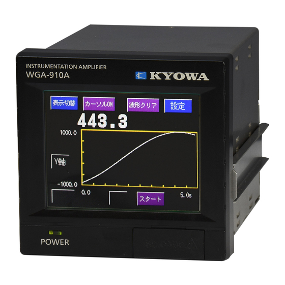
INSTRUMENTATION AMPLIFIER
(FOR CC-Link OPTION)
Thank you for purchasing KYOWA's product WGA-910A Instrumentation
Amplifier.
Read this Instruction Manual carefully in order to make full use of the high
performance capabilities of the product.
Do not use the product in methods other than described in this Manual.
WGA-910A-4: CC-Link
IM-A-1144 July 2017
WGA-910A
Advertisement

Related Manuals for KYOWA WGA-910A Series


Summary of Contents for KYOWA WGA-910A Series
- Page 1 Generally, company names and trade names described in this Instruction Manual are trademarks or registered trademarks of the companies. This Instruction Manual may not be copied or reproduced, in whole or part, without consent of KYOWA. Copyright © Kyowa Electronic Instruments Co., Ltd. All rights reserved.
- Page 2 CONTENTS STANDARD ACCESSORIES ·············································································································1 OPTIONAL ACCESSORIES ··············································································································1 SAFETY PRECAUTIONS (Do not forget to read the safety precautions prior to use.)···········································2 PRECAUTIONS ON CE MARKING ····································································································5 NOTATIONS USED IN THE INSTRUCTION MANUAL ···········································································6 1. OUTLINE OF PRODUCT ··············································································································7 2. CONTROLS AND INDICATORS (REAR PANEL) ················································································7 3.
- Page 3 STANDARD ACCESSORIES The following accessories are packed with the WGA-910A-4. When unpacking, check the contents to ensure that all accessories are enclosed. Instruction Manual 1 (CD-R) Test Certificate and Warranty 1 each OPTIONAL ACCESSORIES <CC-Link connector> Wire mount socket (3M Japan Limited) 35505-6000-B0M GF Branch connector (type-Y, 3M Japan Limited) 35715-L010-B00 AK...
- Page 4 PRIOR TO USE For safe use of the product, do not forget to read the “Safety Precautions” prior to use. Kyowa Electronic Instruments Co., Ltd. assumes no liability for any damage resulting from the user's failure to comply with the safety precautions.
- Page 5 WGA-910A to the measuring object and external devices, PC, etc. Fuse Used for preventing a fire hazard. If you want to replace fuses, contact KYOWA or our representatives. Inflammable Gaseous Environment To prevent fire and explosion hazards, do not operate the WGA-910A where it is exposed to inflammable gases, inflammable vapors or inflammable dust.
- Page 6 CAUTION Caution Be sure to observe the safety precautions described in the WGA-910A Instruction Manual. Do not use the product outdoors Or, it may cause electric shock, fire hazard, lower the performance and cause troubles. Do not turn ON the power switch immediately after turning it OFF After turning OFF the power switch, wait (5 seconds) until the power supply is shut OFF before turning ON the power switch again.
- Page 7 PRECAUTIONS ON CE MARKING NOTE When satisfying the following conditions, we evaluated the compatibility against the requirements of the EU Directives and confirmed that the product satisfied the requirements. To connect products, be sure to use the following cables. Cables applicable to the CC-Link Ver.1.10 (3-conductor shielded twisted-pair cable) Be sure to wrap the CC-Link cable around the clamp-on ferrite core two turns near the connector.
- Page 8 NOTATIONS USED IN THE INSTRUCTION MANUAL The following notations are used in the Instruction Manual for convenience. Names described on the panel surface Names described on the panel surface are expressed in double quotation mark " ". Informational notes Certain notations are used as necessary to attract your attention to information that requires special care when handing the product, and to information provided for reference purposes.
- Page 9 1. OUTLINE OF PRODUCT The WGA-910A-4 is instrumentation amplifier with the CC-Link options. This product is able to control devices and able to load indicated values by using a PLC (or sequencer). 2. CONTROLS AND INDICATORS (REAR PANEL) (1) Communication Connects the CC-Link cable for the PLC.
- Page 10 The applicable connector of the CC-Link cables is as follows. (Optional accessories) Name Model Manufacture Wire mount socket 35505-6000-BOM-GF 3M Japan Limited Branch connector (type-Y) 35715-L010-B00 AK 3M Japan Limited Termination connector 35T05-6M00-BOM GF 3M Japan Limited NOTE To locate the products at both ends of the CC-Link network, be sure to mount the termination connectors.
- Page 11 6. CC-Link SETTINGS 6-1. Number of occupied stations Sets the number of occupied stations as the remote device station. <Setting Range> 1 station, 2 stations, 4 stations. <How to operate> Option Setting Return Measure 1) Press the key on the “Option Setting” window. 'Communication Speed','Trans- CC-Link Setting Com.Setting...
- Page 12 6-2. Communication speed Sets the Communication speed of the CC-Link. <Setting Range> 10 Mbps,5 Mbps,2.5 Mbps,625 kbps,156 kbps <How to operate> 1) Press the key on the “CC-Link Setting” window. CC-Link Setting Return Measure Communiction Speed 'The Number of Occupied Occupied Stations Stations' is set.
- Page 13 7. BUFFER ADDRESS OF PLC When the Number of occupied stations is "2" or "4", make sure each PLC (master) has unique address. The buffer address, assigned to the remote device (WGA-910A), varies with the Station number as follows. Remote input: RX Remote output: RY Remote register: M Remote register: R...
- Page 14 8. ADDRESS MAP 8-1. REMOTE REGISTER: M 8-1-1. Address map of the remote register M M: Master (PLC) R: Remote (WGA-910A) NOTE The buffer address is the value, when the Station number is "1". Number of occupied stations: 4 stations Name Station Buffer...
- Page 15 8-1-2. Format of the remote register M Measureing Condition limited data: 32 bits BCD Buffer address (Station number: 1, Number of occupied stations: 4 stations): 01E0 to 01E7 Writes the pre-set values of the Measureing Condition (operation pattern) limited data by using the [Command processing request 1].
- Page 16 Command data (Clock 2): 32 bits BCD Buffer address (Station number: 1, Number of occupied stations: 4 stations): 01EC to 01ED Write the pre-set values of the Clock 2 (Hour, Minute, Second) by using the [Command processing request 2]. Minute (10 th digit) 4 bits Minute (10 th digit) 4 bits Second (10 th digit) 4 bits Second (10...
- Page 17 8-2. REMOTE REGISTER: R 8-2-1. Address map of the remote register R R: Remote (WGA-910A) M: Master (PLC) NOTE The buffer address is the value, when the Station number is "1". Number of occupied stations: 4 stations Station Name Buffer Remote Remarks address...
- Page 18 8-2-2. Format of the remote register R Indicated value_Selection: 32 bits BCD Buffer address (Station number: 1, Number of occupied stations: 4 stations): 02E0 to 02E1 The data varies with the remote output [Value selection 1]. th digit 4 bits th digit 4 bits th digit...
- Page 19 Error auxiliary code: 4 bits BCD Buffer address (Station number: 1, Number of occupied stations: 4 stations): 02E7 Store the WGA-910A error No. The "0000" indicates there is no error. All "0" 4 bits All "0" 4 bits All "0" 4 bits Error No.
- Page 20 8-3. REMOTE INPUT AND REMOTE OUTPUT 8-3-1. Address map NOTE The buffer address is the value, when the Station number is "1". Number of occupied stations: 4 stations M: Master (PLC) R: Remote (WGA-910A) R: Remote (WGA-910A) M: Master (PLC) Station Buffer Remote...
- Page 21 M: Master (PLC) R: Remote (WGA-910A) R: Remote (WGA-910A) M: Master (PLC) Station Buffer Remote Buffer Remote Name Name address output address input RY0020 to RX0020 to 0162 (Reserved) 00E2 (Reserved) RY002F RX002F RY0030 to RX0030 to 0163 (Reserved) 00E3 (Reserved) RY003F RX003F...
- Page 22 Number of occupied stations: 2 stations M: Master (PLC) R: Remote (WGA-910A) R: Remote (WGA-910A) M: Master (PLC) Station Buffer Remote Buffer Remote Name Name address output address input Command processing Command processing response RY0000 RX0000 request 1 RY0001 (Reserved) RX0001 (Reserved) Command processing...
- Page 23 Number of occupied stations: 1 station M: Master (PLC) R: Remote (WGA-910A) R: Remote (WGA-910A) M: Master (PLC) Station Buffer Remote Buffer Remote Name Name address output address input RY0000 ZERO command RX0000 [HH] comparator RY0001 RESET command RX0001 [HI] comparator RY0002 HOLD command RX0002...
- Page 24 8-3-2. Contents of the remote output RY (M Name Contents Command processing Turn ON when writing the pre-set values of the Measureing Condition (operation request 1 pattern) limited data. Before turning OFF, make sure the [Command processing response 1] is ON. Corresponding to the [/M] command.
- Page 25 8-3-3. Contents of the remote input RX (R Name Contents Command processing Turn ON when the writing of the pre-set values finished. Before turning OFF, make sure the [Command processing request 1] is OFF. response 1 It is the same function as "/ M command" of RS communication. Command processing Turn ON when the writing of the general commands finished.
- Page 26 9. LIST OF COMMANDS All commands are applicable to the [Command processing request 2] / [Command processing response 2]. 9-1. COMMANDS FOR THE MEASUREING CONDITION (OPERATION PATTERN) Command Pre-set value Function Item Comparison [HH]_Comparator 0 5 1 1 -99999 to +99999 Setting [HI]_Comparator 0 5 2 1 -99999 to +99999...
- Page 27 9-2. COMMANDS FOR THE GENERAL SETTINGS Function Item Command Pre-set value Sensitivity Rated output 2 1 0 1 -3.2000 to +3.2000 mV/V Registering (Sensitivity registering calibration only) Calibration Rated display 2 1 0 2 -99999 to +99999 Decimal point position 2 1 0 3 0:None 1:0.0 2:0.00 3:0.000 4:0.0000 No-Load Zero 2 1 0 4 (No set value.)
- Page 28 9-3. COMMANDS FOR THE CONTROL INPUT SIGNALS Function Item Command Pre-set value Control input ZERO command ON 0 0 0 0 11 signals RESET command ON 0 0 0 0 13 HOLD command ON 0 0 0 0 15 Waveform command 0 0 0 0 17 TEDS command ON 0 0 0 0 19...
- Page 29 10. SETTING PROCEDURES MEMO Indicate the buffer address when the No. of occupied stations is "4." 10-1. TO WRITE THE PRE-SET VALUES OF THE MEASUREING CONDITION (OPERATION PATTERN) LIMITED DATA (BY USING THE REQUEST 1) The [command processing request 1] writes the pre-set values (comparator values) of the Measureing Condion limited data.
- Page 30 10-2. TO WRITE THE PRE-SET VALUES OF THE COMMANDS (BY USING THE REQUEST 2) To write the pre-set value in the product, set the [WRITE_READ] to "OFF." When the product turns ON the [Command processing request 2] with the [Command processing request 1], [Command processing request 2], [Command processing response 1], and [Command processing response 2] are all OFF, the command writes the pre-set values in the product (1) With the commands for the Measureing Condition (for details, see "10-1.
- Page 31 10-3. TO READ THE PRE-SET VALUES OF THE COMMANDS (BY USING THE REQUEST 2) To read the pre-set values from the product, set the [WRITE/READ] to "ON." The product outputs the pre-set values. Before reading the [Command data response], make sure the [Command processing response 2] is "ON." (1) With the commands for the Measureing Condition (for details, see "10-1.
- Page 32 10-5. ERROR STATUS FLAG When an error occurs ((1)) on the product, the product turns OFF the [Remote READY] and turns ON the [Error status flag] ((2)). Turn ON the [Error reset request flag] ((3)) from the master, to turn OFF the [Error status flag] ((4)) and to turn ON the [Remote READY] ((5)).
- Page 33 If the product is damaged due to any causes other than as written in the Instruction Manual or if the user has disassembled or remodeled the product, Kyowa Electronic Instruments Co., Ltd. may not be able to offer repair service.
- Page 34 Maintenance service should be performed at the intervals specified below. (1) Calibration of apparatus An annual maintenance inspection is recommended to ensure the operation and measuring accuracy of the product. Must be returned to KYOWA for the scheduled maintenance inspection. (2) Replacement of limited life parts Item Content...
- Page 35 13. OUTSIDE DRAWING Unit: mm...
- Page 36 Kyowa Electronic Instruments Co., Ltd. 3-5-1, Chofugaoka, Chofu, Tokyo 182-8520 Japan http://www.kyowa-ei.com/...
Need help?
Do you have a question about the WGA-910A Series and is the answer not in the manual?
Questions and answers