
Subscribe to Our Youtube Channel
Related Manuals for KYOWA WGA-120A


Summary of Contents for KYOWA WGA-120A
- Page 1 IM-A-1011B Au ugust, 2014 INSTRUCT TION MAN NUAL A-120 CARR RIER TYPE IN NSTRUMENTA ATION AMPL LIFIER...
- Page 3 Generally, company names and trade names described in this Instruction Manual are trademarks or registered trademarks of the companies. This Instruction Manual may not be copied or reproduced, in whole or part, without consent of KYOWA. Copyright © Kyowa Electronic Instruments Co., Ltd. All rights reserved.
-
Page 4: Table Of Contents
3-1 TO FIX THE WGA-120A ....................28 3-1-1 To mount the WGA-120A onto the panel ..............28 3-1-2 To mount the WGA-120A onto the DIN rail ..............29 3-2 TO CONNECT POWER SUPPLY ..................30 3-3 TO CONNECT TRANSDUCERS ..................32 3-4 TO CONNECT TRANSDUCERS IN PARALLEL ............. - Page 5 4. OPERATION PROCEDURES ....................38 4-1 TO TURN ON THE POWER .................... 40 4-2 TO ADJUST THE ZERO BALANCE ................40 4-3 TO ADJUST THE SPAN ....................41 4-3-1 By the actual load calibration ..................41 4-3-2 By the CAL ........................ 44 4-4 CORRECTION REQUIRED WHEN AN EXTENSION CABLE WAS USED ....
-
Page 6: Safety Precautions (Do Not Forget To Read The Safety Precautions Prior To Use.)
Also, keep the manual within easy reach so that you can refer to it whenever necessary. For safe use of the WGA-120A, do not forget to read the "Safety Precautions" prior to use. Kyowa Electronic Instruments Co., Ltd. assumes no liability for any damage resulting from the user's... - Page 7 For safety operation of the WGA-120A, the following symbol marks are used in the Instruction Manual. Indicates “PROTECTIVE GROUND TERMINAL.” Be sure to connect the GND terminal to the ground. For safety operation of the WGA-120A, the following symbol marks are used in the Instruction Manual.
- Page 8 △ ! WARNING Power supply To prevent a fire hazard, ensure that the power supply voltage specified for the WGA-120A matches the local line voltage before turning ON the power. The power supply voltages are described in the following. DC model: 10.5 to 15 VDC, power dissipation 3.5 W or less...
- Page 9 Confirmation of protective functions To prevent electric shock hazards, when any trouble occurs in protective functions including the GND terminal and a fuse, do not to operate the product. Furthermore, before operating the product, always check whether error exists or not in protective functions. Fuse When the pilot lamp does not light up, the fuse may be blown.
- Page 10 Storage and usage in gases Do not use/store the WGA-120A in inflammable gases, explosive gases, or vapor. Using the WGA-120A under the above environment is too risky. External connection To prevent electric shock hazards, be sure to connect the GND terminal to the ground before connecting the object to be measured and external control circuit to the product.
- Page 11 Power supply Use the WGA-120A within the specified power voltage. The WGA-120A has 4 types: 10.5 to 15 VDC, 100 VAC, 200 VAC, 240 VAC. (We are able to manufacture 110 VAC model and 220 VAC model.) PRECAUTIONS FOR USE...
- Page 12 Do not disassemble or remodel the WGA-120A. It may cause electric shock hazards or damage the WGA-120A. This warranty does not cover any damaged or defective parts that results from disassembling or remodeling. The output signal (voltage/current) when the transducer cable is broken.
- Page 13 Using them exceeding the years specified according to each part type (useful life) may affect the characteristics of the WGA-120A, resulting in a malfunction or a failure. You need to replace parts with a regular preventive maintenance schedule.
- Page 14 Preventive maintenance and replacement parts are a cost-effective way of keeping the performance and extending the service life of the WGA-120A. Regardless of the replacement parts, the WGA-120A itself gradually deteriorates with age. Before the expected service life is reached, consider replacing the...
- Page 15 Precautions on CE marking Be sure to mount the WGA-120A on the control panel, etc. Before turning ON the power, make sure the WGA-120A is covered to avoid contact with hands. The WGA-120A connection, jumper changing, BAL/CAL switch operation, adjuster operations, and fuse replacement should be executed by experts in electrical work.
- Page 16 Function ZERO balance The WGA-120A has manual balance model and auto balance model (external contact points are also available). The WGA-120A is able to change excitation voltage, output signal (voltage/current), sensitivity, calibration value (CAL), and frequency response.
- Page 17 Model The WGA-120A series has 8 models. Customers are required to purchase the power cable applied for your power supply specifications. Model Balance adjustment Power supply specs WGA-120A-00 Manual WGA-120A-01 Manual 100 VAC WGA-120A-02 Manual 200 VAC WGA-120A-03 Manual 240 VAC...
-
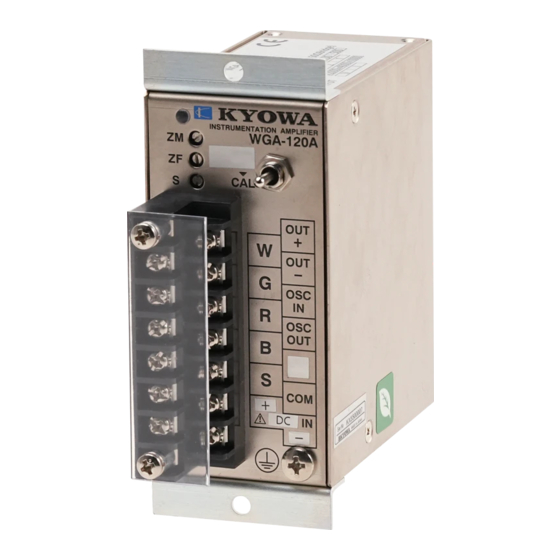
Page 18: Controls And Indicators
CONTROL LS AND INDICATOR -13-... - Page 19 Pilot lamp Lights up in green while the power is supplied to the WGA-120A. When the WGA-120A is slave unit in the synchronous operation, the pilot lamp lights up in orange. (See “3-5 TO USE STRAIN GAGES.”) ZERO coarse adjuster(ZM) Coarse adjusts the ZERO of the output signal (voltage/current).
- Page 20 (See “4-5 AUTO BALANCE ADJUSTMENT.”) Power supply input terminal Power supply terminal. Power supply varies with WGA-120A models. Carefully read the Specifications before connecting the power supply. Protective ground terminal GND terminal. Be sure to connect the product to the ground before turning ON the power.
-
Page 21: Initial Settings
2. INITIAL SETTINGS This section describes how to select the bridge excitation voltage, output signal (voltage/current), sensitivity, CAL, frequency response by using jumpers on the built-in PCBs. Be sure to read this section prior to use. Factory-configured settings Bridge excitation voltage: 1 Vrms Input: 5mV/V (=5000µV/V), Output: 10 V Output signal:... -
Page 22: To Change Jumpers (Manual Balance Model)
Remove screws (on b both sides). ② Remove 4 flat t head screws (M2.6) locat ted on the WGA-120A side panels. R Remove the cover. ③ Change the jum mpers (JP1 to JP8) on the PCB to your desired settings. -
Page 23: To Change Jumpers (Auto Balance Model)
① Disconnect the e power cable. Remove screws (on bot th sides). ② Remove 4 flat t head screws (M2.6) locat ted on the WGA-120A side panel. ③ Remove the A Auto balance PCB (40×30 m mm) from the WGA-120A m main PCB. - Page 24 NOTE Do not change jumpers under dusty environment or humid place. Do not take procedures other than what is described on the 2-1 and 2-2. Or, it may cause trouble. Do not touch the other parts or do not remove screws other than the specified screws.
- Page 25 3 to 6 3 to 4 3 to 4 0.25mV/V 2 to 3 0.05mV/V 1 to 2 Frequency response 10Hz 1 to 2 30Hz 3 to 6 100Hz 2 to 5 500Hz 1 to 4 mpers in the WGA-120A -20-...
- Page 26 le 2-1 Jumper settings 1 Setting items Setting contents Jumper settings Jumper setting figure Bridge 1 Vrms 1, between 2 to 4 excitation Applicable 7, between 1 to 2 voltage bridge resistance 8, between 1 to 2 87.5 to 1000 ohm 2 Vrms 1, between 1 to 2 (Be sure to set...
- Page 27 le 2-2 Jumper settings 2 Setting items Setting contents Jumper settings Jumper setting figure Output Voltage 2, between 1 to 2 Current 2, between 2 to 3 Sensitivity ×10000 3, between 1 to 4 4, between 1 to 3 (Auto balance model: The JP3 ×4000 3, between 2 to 5...
- Page 28 le 2-3 Jumper settings 3 Setting items Setting contents Jumper settings Jumper setting figure 0.25mV/V 5, between 2 to 3 0.05mV/V 5, between 1 to 2 Frequency 10 Hz 6, between 1 to 2 response 30 Hz 6, between 3 to 6 100 Hz 6, between 2 to 5 500 Hz...
- Page 29 Table 2-4 Available range to be output the full scale value (voltage: ±10 V, current: 20 mA) Input range (mV/V) Sensitive Bridge excitation SPAN range switch voltage (Vrms) × 1 × 0.4 ±5 ±12.5 × 2000 ±2.5 ±6.25 ±1 ±2.5 ±2.5 ±6.25 ×...
-
Page 30: Example Of Changing Jumpers
2-3 EXAMPLE OF CHANGING JUMPE [For using Kyow a's load cell LMR-S-5KN SA2] ① Find the test d data sheet of the LMR-S-5K KNSA2. Rated capacity Rated output 1293 µV/V (=1.2 293mV/V) Calibration constant 0.003868kN/1 µ µV/V Input & output resistance 351.6 6 ohm -25-... - Page 31 When the bridge resistance (input & output resistances on the test data sheet) is 175 ohm or more, the WGA-120A is able to use any excitation voltage. Since the input & output resistances of the LMR-S-5KNSA2 is 351.6 ohm, the WGA-120A is able to use any excitation voltage. However, the recommended excitation voltage of the LMR-S-5KNSA2, described on the instruction manual, is 1 to 2 V.
- Page 32 ④ Set the sensitivity. Since the excitation voltage is 2Vrms in the ②, to output the full scale value, the sensitivity should be ×4000. Set the sensitivity ×4000. (“Sensitivity: ×4000” JP3: Between 2 to 5, JP4: Between 2 to 4) ⑤...
-
Page 33: Connection
3. CONNECTION The WGA-120A does not include cables since the WGA-120A is an amplifier, designed to be used in a system. The WGA-120A is able to mount by using 2 holes (φ4.5) on the fitting metal. The WGA-120A is able to mount on the DIN rail by using Kyowa's DIN rail mounting plate (optional: EDP-70). -
Page 34: To Mount The Wga-120A Onto The Din Rail
DI IN rail by mounting the D DIN rail mounting plate (ED DP-70, optional) onto the e WGA-120A rear panel. T The WGA-120A has holes s (described as follows) on n its rear panel for fixing th he DIN rail mounting plat te. -
Page 35: To Connect Power Supply
(1) For 100 VAC model/200 VAC model/240 VAC model The terminal block has terminal cover. Before connecting the AC power cable to the Power supply input terminal, remove the terminal cover. Use Kyowa's AC power cable (optional). AC power cable for 100 VAC: P-23... - Page 36 (2) For DC power supply model Use cables having the solderless terminal for copper wire 1.25-3 (conforming to JIS C 2805) or equivalent. Connect the power supply, 10.5 to 15 V (200 mA or more), to the Power supply input terminal. The withstand voltage of the cable should be the power supply voltage or more.
-
Page 37: To Connect Transducers
Transducer input terminal 3-4 TO CONNE CT TRANSDUCERS IN N PARALLEL The WGA-120A connects up to 4 transduc ers (bridge resistance: 350 0 ohm) in parallel. Transducers shou uld be the same model and d same capacity. At this tim me, the bridge resistance is s 87.5 ohm. - Page 38 Securely connect the transducers to the terminal block. Or, it may cause troubles. The WGA-120A amplifies (×2000 to ×10000) the minute electrical signals to output the output signal (±10V or 4 to 20mA). The WGA-120A also amplifies (×2000 to ×10000) small noises.
-
Page 39: To Use Strain Gages
3-5 TO USE STR RAIN GAGES To measure multi iple strains at the same tim me by using strain gages an nd multiple WGA-120A un nits, be sure to synchroni ize the oscillator signals. T The synchronous operation n prevents beat, due to the... - Page 40 MEMO Beat phenom menon The WGA-1 120A uses the oscillator sig gnals, generated inside the e WGA-120A, for operatio ons. Suppose stra ain gages are bonded to th e same object to be measu ured. When measuring data a by...
-
Page 41: To Connect The Auto Balance Control Input Terminal
3-6 TO CONNECT THE AUTO BALANCE CONTROL INPUT TERMINAL The Auto balance control input terminal (AZ and COM) on the terminal block is designed to execute the auto balance adjustment. Use a contact point (switch or relay). Terminals for executing the auto balance adjustment are as follows. Terminal block External Internal... -
Page 42: To Connect The Output Terminal
OUT + : Positive side of the voltage output/current output(±10 V or 4 to 20 mA) OUT - : Negative side of the voltage output/current output (the same potential as the COM) The WGA-120A is able to change the output signal (voltage/current) by using the internal jumpers. For details, see “2. INITIAL SETTINGS”. -
Page 43: Operation Procedures
4. OPERATION PROCEDURES Make sure all wires are correctly connected. Turn ON the power. The pilot lamp lights up. Preheat the WGA-120A approximately 30 minutes. Initialize the load or weight of the transducer. (Normally, no load is applied or weight is 0.) - Page 44 When the fine-adjustment is required, fine-adjust the output signal (voltage) to be 0 V (current: 4mA), by turning the ZERO fine adjuster. Sensitivity adjustment Actual load calibration based on the CAL Apply the actual (known) load or weight to When the Actual Load Calibration is not the transducers.
-
Page 45: To Turn On The Power
4-1 TO TURN ON THE POWER Before turning ON the power, make sure the WGA-120A is correctly connected. Although the WGA-120A will be in operating state immediately after turning ON the power, we recommend you to preheat the WGA-120A 30 minutes for stable measurements. -
Page 46: To Adjust The Span
The above procedures indicate how to adjust the ZERO by using the output signal (voltage). The WGA-120A is also able to adjust the ZERO by using the output signal (current). The output signals (current: 4 to 20 mA) move in tandem with the output signals (voltage: 0 to +10). - Page 47 Then, with the weight (1kN) applied to the load cell, adjust the output signal to be 1.00 V or 10.00 V for reading the weight directly. Suppose the WGA-120A outputs 1.00 V when applying the weight (1kN). When the WGA-120A outputs 0.80V, the applied weight is 0.8kN.
- Page 48 [Example 2] Actual load calibration 2 Load cell Rated capacity: 1kN Assume that 5 V output signal is required when 1kN is loaded. When applying the weight (0.8kN), the output signal (voltage, V) is as follows. 0.8×5 Output = = 4 (V) First, with the no load applied, turn the Sensitivity adjuster all the way to the right to execute the balance adjustment.
-
Page 49: By The Cal
4-3-2 By the CAL Make sure no load is applied to the transducers (weight: 0). Adjust the value on the digital voltmeter, connected to the Output terminal (OUT+ and OUT-), by turning the Sensitivity adjuster with the BAL/CAL switch pushed down. The CAL varies with the bridge resistances to be connected. - Page 50 MEMO The CALs are based on the 350-ohm bridge. The CALs are based on the parallel resistance method. The WGA-120A connects the parallel resistors (described in the above table) between the G terminal and R terminal while the BAL/CAL switch is pushed down.
- Page 51 When using the other bridge resistances, described in the table 4-1, calculate the CAL (mV/V) by using the following formula. CAL = × 10 (mV/V) (Formula 4-1) 4(Rc+Rg) Rg: Bridge resistance (ohm) Rc: Parallel resistors CAL 0.25mV/V: Substitute 350×10 (ohm) CAL 0.05mV/V: Substitute 1750×10 (ohm)
- Page 52 [Example 1] How to calculate the CAL CAL: 0.25mV/V, Bridge resistance: 500 ohm The actual CAL to be used is as follows. CAL = × 10 4(Rc+Rg) × 10 = 0.357 (mV/V) 4 (350 × 10 + 500) -47-...
- Page 53 Load cell Rated capacity: Bridge resistance: 1000 ohm Calibration constant: 0.0005005kN/1μV/V (= 0.5005kN/1mV/V) *Calibration constant: Unique value described on the test data sheet CAL of the WGA-120A 0.25mV/V (350-ohm bridge), that is, 0.712mV/V (1000-ohm bridge, see the table 4-1) -48-...
- Page 54 The above procedures indicate how to adjust the ZERO by using the output signal (voltage). The WGA-120A is also able to adjust the ZERO by using the output signal (current). The output signals (current: 4 to 20 mA) move in tandem with the output signals (voltage: 0 to +10).
-
Page 55: Correction Required When An Extension Cable Was Used
4-4 CORRECTION REQUIRED WHEN AN EXTENSION CABLE WAS USED When using an extension cable, the measured value contains an error due to an extension cable. The longer an extension cable is used, the larger a measurement error grows. In order to remove this error, multiply the measured value by a correction value. - Page 56 × 10 (Formula 4-2) L: Cable length (m) ρ: Cable resistivity (ohm・m) S: Cable cross section(mm When using Kyowa's extension cables (N-81 to 85, N-100), ρ is 1.7×10 (ohm・m). ② Calculate the correction value. Correction value = r × A +1...
- Page 57 Then, with an extension cable connected, execute the sensitivity adjustment by the CAL to output 4 V when the CAL is 0.25mV/V. After the sensitivity adjustment, the WGA-120A outputs 5.00 V. To calculate the true output, remove the cable extension errors as follows.
-
Page 58: Auto Balance Adjustment
After executing the auto balance adjustment, the WGA-120A outputs the output signal (voltage) 0V. The WGA-120A outputs the output signal (current) 4mA. Even if the WGA-120A is turned OFF, the state of the output signal (voltage/current) are maintained to have the same state before the power OFF. - Page 59 NOTE Take care no chattering generates on the slope (negative) and slope (positive) of the contact point signal. -54-...
-
Page 60: Specifications
5. SPECIFICATIONS 5-1 SPECIFICATIONS Applicable Transducer Strain gage transducers Number of Measuring Channels Applicable Bridge Resistance 87.5 to 1000 ohm (Up to four 350-ohm transducers can be connected in parallel. Bridge excitation voltage is limited to 2 or 1 Vrms for transducers with bridge resistance less than 175 ohm) Bridge Excitation Voltage 5 Vrms, 2 Vrms, or 1 Vrms, Square wave... - Page 61 Zero Adjustment Range Within ±1.5 mV/V, manual balance or auto balance by selecting model. Sensitivity Adjustment Range ×2000, ×4000, ×10000 (Switchable by changing internal jumper connection) Adjustable between ×0.4 and ×1.0 by the trimmer. Calibration Calibration by the parallel resistance method 0.25mV/V or 0.05mV/V at 350-ohm bridge resistance (Switchable by changing internal jumper connection) Frequency Response...
- Page 62 Stability Temperature Zero: Within ±0.2μV /℃ Sensitivity: Within ±0.05%/℃ Time Zero: Within ±0.5μV Sensitivity: Within ±0.2%/8H [Conditions] Sensitivity: ×10000, ×1.0(Adjustment by the trimmer), Bridge resistance: 120 ohm, Bridge excitation voltage: 2 Vrms Applicable Standards EMC standards EN61326-1 (Class A) Safety standards EN61010-1 EN61010-2-030 (Installation category II,Pollution degree 2, Measureing...
- Page 63 Power Supply Voltage/Power Consumption 10.5 to 15 VDC, 3.5W or less 90 to 110 VAC, 6.5VA or less 180 to 220 VAC, 6.5VA or less 216 to 264 VAC, 6.5VA or less (Varies with the models) Dimensions 44 (W) × 90 (H) ×80 (D) mm (excluding protrusions) Weight DC power supply model: Approx.
- Page 64 Transducer's outp p ut and output signal (volt age/current) -59-...
- Page 65 Available range to be output the full scale value (voltage: ±10 V, current: 20 mA) Input range (mV/V) Sensitive Bridge excitation SPAN range switch voltage (Vrms) × 1 × 0.4 ±5 ±12.5 × 2000 ±2.5 ±6.25 ±1 ±2.5 ±2.5 ±6.25 ×...
-
Page 66: Block Diagram
5-2 BLOCK DIA AGRAM Some models d do not have the Auto-BAL circuit. -61-... -
Page 67: Dimensions
5-3 DIMENSIONS -62-... - Page 68 Panel cut dimen nsion × 93.4 -63-...
- Page 72 取扱説 説明書 A-120 搬送波 波型計装用増 増幅器...
- Page 74 取扱説明書 WGA-120A 搬送波型計装用増幅器 このたびは,共和電業の製品をお買い求めいただきまして誠にありがとうございます。この取 扱説明書をよくお読みいただき,末永くご愛用いただきますようお願い申し上げます。 取扱説明書に説明されている以外の方法ではお使いにならないでください。 取扱説明書に記載した会社名,商品名は一般的に各社の商標または登録商標です。 本製品の一部または全部を無断で複写・複製することを禁止します。 本製品は株式会社共和電業の著作物であり,その著作権は株式会社共和電業に帰属します。 取扱説明書の内容は,予告なく変更することがあります。 株式会社 共和電業...
- Page 75 目次 安全上のご注意(ご使用前に必ずお読みください) ................1 1.各部の名称 ..........................13 2.初期設定 ..........................15 2-1 ジャンパピンの切り換え手順(マニュアルバランス仕様の場合) ........16 2-2 ジャンパピンの切り換え手順(オートバランス仕様の場合) ..........17 2-3 ジャンパピンの設定手順例 .................... 24 3.接続 ............................27 3-1 本体の固定 ........................27 3-1-1 パネルへの取り付け.................... 27 3-1-2 DINレールへの取り付け ..................28 3-2 電源の接続 ........................29 3-3...
- Page 76 4.操作手順 ..........................37 4-1 電源の投入 ........................39 4-2 初期バランスの調整 ..................... 39 4-3 感度(SPAN)の調整 ....................40 4-3-1 実負荷による感度調整 ..................40 4-3-2 校正値(CAL)による感度調整 ................41 4-4 延長ケーブルを使用した場合の補正 ................45 4-5 オートバランスの動作 ....................48 5.仕様 ............................49 5-1 仕様 ..........................49 5-2 ブロック図 ........................55 5-3...
-
Page 77: 安全上のご注意(ご使用前に必ずお読みください
安全上のご注意(ご使用前に必ずお読みください) ■ご使用の前に ご使用の前に,この「安全上のご注意」をよくお読みください。 お読みになったあとは,いつでも見られるところに必ず保管してください。 ご使用に際しては,下記の安全注意事項を必ずお守りください。 なお,これらの注意に反したご使用により生じた傷害につきましては,(株)共和電業は責任と保 証を負いかねます。... - Page 78 ■本機器には,安全にご使用していただくために,下記シンボルマークを使用しています。 :保護接地端子を示します。 本機器にこの表示のある端子は,必ず接地してください。 ■この「安全上のご注意」および本機器には,安全にご使用していただくために,下記警告表示が使 用されています。 :取り扱いを誤った時,使用者が死亡または重傷を負う可能性が想定さ △ 警告 ! れる場合。 △ :取り扱いを誤った時,使用者が損害を負う危険が想定される場合,お 注意 ! よび物的損害の発生が想定される場合。...
- Page 79 △ 警告 ! ●電源 火災防止のため,本機器の電源電圧仕様と,お使いになる電源の電圧が合っていることを,必 ず確認したうえで,本機器の電源を入れてください。 本機器の電源電圧仕様を,以下に示します。 DC仕様 :DC10.5~DC15V,消費電力3.5W以下 AC100V仕様:AC90V~AC110V,消費電力6.5VA以下 AC200V仕様:AC180V~AC220V,消費電力6.5VA以下 AC240V仕様:AC216V~AC264V,消費電力6.5VA以下 ●電源コードと電源コンセント 本機器には,電源スイッチがありません。本機器に電源コードを接続する際には,分電盤など から電源が供給されていないことを確認してから作業を行ってください。感電あるいは製品の 損傷の恐れがあります。 ●保護接地 感電防止のため,本機器の電源を入れる前には,必ず保護接地を行ってください。 電源コードが平行ビニル線で2極のものを使用する場合は,別途アース線で保護接地端子を必 ず接地してください。...
- Page 80 ●保護機能の確認 感電防止のため, 保護接地端子およびヒューズなどの保護機能に異常があると思われるときは, 本機器を動作させないでください。また本機器を動作させる前には,保護機能に異常がないか 確認してご使用ください。 ●ヒューズ パイロットランプが点灯しないときは,ヒューズが切れている可能性があります。 ヒューズを交換する際は,本機器で使用された定格(電流,電圧,タイプ)のものをご使用く ださい。指定外のヒューズを用いたり,ヒューズホルダを短絡したりしないでください。ヒュ ーズの交換は,電源プラグを抜いてから行ってください。 以下のヒューズを使用してください。 DC仕様 リセッタブルヒューズ (交換の必要はありません。 ) AC100V仕様 AC200V仕様 速断 100mA 250V 直径5mm,長さ20mm AC240V仕様...
- Page 81 ●ガス中での保管,使用 可燃性,爆発性のガスまたは蒸気のある場所では,本機器を保管および使用しないでください。 そのような環境下で本機器を使用することは危険です。 ●外部接続 感電防止のため保護接地を確実に行ってから,測定対象機器や外部制御回路への接続を行って ください。 ●端子カバー 端子台付属の端子カバーを必ずご使用ください。感電の恐れがあります。...
- Page 82 △ 注意 ! ●使用電源 電源は必ず指定の電源電圧で使用してください。 DC10.5V~15V,AC100V,AC200V,AC240Vの4種類があります。 (AC110V,AC220Vの製作も可能です。 ) 取扱上の注意 ●外来ノイズについて 入力ケーブル(変換器と本器の間)の近くに電力線,トランス,電動工具,モータ,トランシ ーバなどノイズの原因となる心配がある場合はノイズ対策を行ってください。 ●強い電磁界中では使用しないでください 無線機,電子レンジ,電気炉などの強い電磁界を発生する機器の周辺で使用すると,性能の低 下,誤動作,故障の原因となります。 ●溶接機の近くへのセンサの設置や溶接機の近くでの測定は行わないでください。 データの異常,誤動作,故障の原因となります。...
- Page 83 ●分解,改造をしないでください。 感電,故障の原因になります。また保証対象外となります。 ●入力断線時の電圧出力,電流出力について 接続されている変換器のケーブルが断線した場合には,本器の電圧出力および電流出力が,以 下の通りになることがあります。したがって,この出力信号が他の機器へ悪影響を与えないよ うに対策をしてください。 電圧出力:-13V付近 電流出力:0mA付近 ●出力の取り出し方(負荷)について 電圧出力:2kΩ以上の不平衡負荷でご使用ください。 電流出力:500Ω以下の不平衡負荷でご使用ください。 ●使用(設置)場所について 温度-10℃~+50℃ 湿度20~85%RH以下の範囲でご使用ください。 大きな振動や衝撃の加わる環境,ほこりの多い環境,水滴のかかる環境では使用しないでくだ さい。これらの環境で使用しますと性能低下や故障の原因になります。 ●清掃について 本器が汚れた際には,乾いた柔らかい布で清掃してください。本体内部に埃などが付着してい る場合はエアブローで清掃し,電子部品には触らないでください。...
- Page 84 保守点検について 本器は多数の電気部品から構成されており,その中には有寿命部品も含まれています。 有寿命部品は,使用頻度や経過時間,使用環境(温度・湿度)等により,劣化が進行し,性能 の低下,誤動作,故障の原因となる場合があります。 よって保守点検により,部品の交換が必要となります。 本器および別売品で使用している有寿命部品について,下記に表記します。 ◯ アルミ電解コンデンサ 容量変化による SN 比の低下や,液漏れによる発煙,誤動作に至る場合があります。 ◯ EEPROM 性能劣化により誤動作に至る場合があります。 本器を長期間安定してご使用いただくためには,定期的な保守による点検および部品交換が必 要となります。保守点検,有寿命品の交換につきましては,お手数でも弊社営業所または最寄 りの代理店までお問い合わせください。 ※ 有寿命部品以外の部品も経年変化は発生し,故障する場合があります。...
- Page 85 機器の更新について 機器の保守点検・部品交換は,性能を維持し機器寿命を延命させる有効な手段といえます。し かしながら交換可能な部品は消耗品,有寿命部品に限られるため,機器全体の経年劣化は徐々 にではありますが進んでいきます。長期使用され修理頻度の高くなった機器は更新を検討され ることを推奨します。...
- Page 86 CEマーキングに関する注意事項 ●本器は, 必ず制御盤等に設置固定してください。 また電源をONにして通常使用する場合は, 本器に触れられないように対策を施してください。 ●本器の接続およびジャンパ切り換え,BAL/CALスイッチ,調整用トリマの操作,ヒュ ーズ交換は,電気工事などの専門知識を有する設置者が行ってください。 ●本器の電源を速やかにOFFできるように,本器を使用する建屋および本器のすぐ近くにス イッチまたは遮断機を設置し,そこにその機能を表示してください。スイッチや遮断機は, IEC60947-1およびIEC60947-3の該当要求事項に適合したものを使用し てください。 ●高度2000m以下でご使用ください。 ●本器をお客様の装置に組み込む際,ご使用になる制御盤の構成,接続される他の機器や配線 等により,CEマーキングへ適合させるための対策が必要になります。したがって,お客様 にて装置全体でCEマーキングへの適合を確認していただく必要があります。 ●接続する入力ケーブル,出力ケーブル,制御ケーブル等は,シールドケーブルを使用してく ださい。 -10-...
- Page 87 概要 本器は,ひずみゲージ式変換器を用いて荷重,圧力,トルク,変位などを測定する小型,軽 量の搬送波型計装用増幅器です。 機能 ・零点調整の方式 マニュアルバランス式とオートバランス式 (外部接点でも可能) の2機種を用意しています。 ・ブリッジ電源電圧,出力(電圧/電流) ,感度,校正値,周波数特性が切り換え可能 内部ジャンパで切り換えが可能で,特性変更が容易にできます。 標準付属品 本器は下記の付属品が付いています。梱包を開けましたら,付属品が揃っていることをお確 かめ下さい。 ---------------各1部 ・検査票・保証書 ・取扱説明書 --------------------------1部 参 考:電源ケーブルは付属していません。ご使用電源に合ったケーブルをご使用ください。 別売品:AC電源ケーブル100V用 P-23 AC電源ケーブル200V/240V用 P-28 DINレール取付プレート EDP-70 -11-...
- Page 88 機種 WGA-120Aシリーズは,仕様により全部で8種類あります。お買い求めになりました機 種をお確かめの上,電源仕様に合った電源を接続してご使用ください。 型式 バランス 電源仕様 WGA-120A-00 マニュアル DC WGA-120A-01 マニュアル AC100V WGA-120A-02 マニュアル AC200V WGA-120A-03 マニュアル AC240V WGA-120A-10 オート DC WGA-120A-11 オート AC100V WGA-120A-12 オート AC200V WGA-120A-13 オート AC240V -12-...
-
Page 89: 1.各部の名称
1. 各部の名称 称 -13-... - Page 90 パイロットランプ :電源が供給されているときに緑点灯します。 OSC同期時でスレーブの場合は,橙色点灯します。 (3-5参照) 零点粗調整用トリマ :電圧出力および電流出力の零点を粗調整するためのトリマです。 オートバランス仕様の機種は,このトリマは使用できません。 零点微調整用トリマ :電圧出力および電流出力の零点を微調整するためのトリマです。 感度調整用トリマ :電圧出力および電流出力の感度を調整するためのトリマです。 BAL/CALスイッチ :スイッチのレバーを0.5秒以内に2回押し上げるとオートバランスが実行さ れます。マニュアルバランス仕様では,同様のスイッチ操作を行ってもオー トバランスは実行されません。レバーを押し下げている間は,電圧出力また は電流出力に校正値(CAL)が加算されます。 変換器入力端子 :ひずみゲージ式変換器を接続するための端子です。 出力端子 :ひずみゲージ式変換器からの入力に比例した電圧または電流が出力されます。 同期端子 :本器をOSC同期して使用するとき,この端子を接続します。(3-5参照) オートバランス実行端子 :オートバランス仕様の機種のみ,AZ-COM間を0.5秒以内に2回短絡す ると,オートバランスが実行されます。 (4-5参照) 電源入力端子 :電源を供給するための端子です。機種によって供給する電源の種類が異なり ます。仕様を確認して電源を接続してください。 保護接地端子 :保護接地のための端子です。本器の電源を入れる前に必ず保護接地を行って ください。 -14-...
-
Page 91: 2.初期設定
2.初期設定 本器は,ブリッジ電源電圧,出力(電圧/電流) ,感度,校正値,周波数特性を内部のプリント基 板上のジャンパピンで選択できるようになっております。ご使用前に,本項をよく読み設定を 行ってください。 工場出荷時の設定 ブリッジ電源電圧 1Vrms 5mV/V(=5000μV/V)入力で10V出力 出力 電圧 (5mV/V×1Vrms×2000=10V) 感度 ×2000 校正値 0.25mV/V (ブリッジ抵抗350Ωの場合) 周波数特性 10Hz 各ジャンパピンは,次の内容を参考に設定してください。 ・ブリッジ電源電圧 変換器の推奨印加電圧と入出力抵抗 ・感度 変換器の定格出力と表2-4(23ページ) ・校正値 表4-1(42ページ)あるいは式4-1(43ページ) ・周波数特性 測定したい現象周波数の2倍以上 初期設定の例は24~26ページを参照してください。 -15-... -
Page 92: 2-1 ジャンパピンの切り換え手順(マニュアルバランス仕様の場合
外す(両 両面とも) 2-1 ジャンパピ ピンの切り換え手順(マニ ニュアルバランス仕様の場 場合) ①電源を切りま す。 ②本体側面にあ あるサラネジM2.6(4 本)を外し, カバーを外し してください。 ③本体の基板の のジャンパ(JP1~JP8) をお客様のご使用にな なる せます。 JP1~JP8の基 設定に合わせ 基板上の位置は19ページ ジを 参照してくだ ださい。 ④本体側面にサ サラネジ(4本)でカバー ーを取り付けてください い。 【設定例】 ブリッジ電源電 電圧 2Vrms 出力 電圧出力 感度切換 ×10000 校正値 0.25mV/V( 350Ωの時) 周波数特性... -
Page 93: 2-2 ジャンパピンの切り換え手順(オートバランス仕様の場合
2-2 ジャンパピ ピンの切り換え手順(オー ートバランス仕様の場合) 外す(両 両面とも) ①電源を切りま す。 ②本体側面にあ あるサラネジM2.6(4 本)を外し, カバーを外し してください。 ③オートバラン ンス基板(40×30mm m程度)を本体の メイン基板か から外します。 JP4~JP8)をお客様の ④本体の基板の のジャンパ(JP1,JP2, の P1~JP8の基板上の位置は ご使用になる 設定に合わせます。JP は 19ページを を参照してください。 J4に ⑤オートバラン ンス基板を本体の基板に装 装着します。コネクタJ しっかり取り 付けてください。 ⑥本体側面にサ サラネジ(4本)でカバー ーを取り付けてください い。 オートバランス基板 【設定例】 ブリッジ電源... - Page 94 ご注意 ・設定作業は,ほこりの多い場所,湿度の高い場所などで行わないでください。 ・ジャンパピンの切り換え手順に書かれていないことは行わないでください。故障の原 因になります。他の部品に触ったり,指定以外のネジを外したりしないでください。 ・ジャンパピンの切り換えは,ピンセット,ラジオペンチなどで行ってください。直接, 手でジャンパピン,他電子部品を触らないでください。静電気により壊れることがあ ります。 -18-...
- Page 95 ブリッジ電源電圧 圧 1Vrms 2-4間 1-2間 2間 2Vrms 1-2間 1-2間 2間 5Vrms 1-3間 2-3間 3間 出力 電圧 1-2間 電流 2-3間 マニュアルバランス オ オートバランス 感度 ×10000 1-4間 1-3間 1-3間 な なし ×4000 2-5間 2-4間 2-4間 ×2000 3-6間 3-4間 3-4間 校正値 0.25mV/V 2-3間 0.05mV/V 1-2間...
- Page 96 表2 -1.ジャンパ設定1 設定項目 設定内容 ジャン ンパ設定 ジャンパ設 設定図 ブリッジ電源 1Vrms 2-4間 電圧(BV) (適用ブリッジ抵抗 1-2間 87.5~1000Ω) 1-2間 (JP1,7,8 は必ず ず 右表のいずれか か 2Vrms 1-2間 の組み合わせに に (適用ブリッジ抵抗 1-2間 してください。) 87.5~1000Ω) 1-2間 5Vrms 1-3間 (適用ブリッジ抵抗 2-3間 175~1000Ω) 2-3間 -20-...
- Page 97 表2 -2.ジャンパ設定2 設定項目 設定内容 ジャン ンパ設定 ジャンパ設 設定図 出力 電圧 JP2 2 1-2間 電流 JP2 2 2-3間 感度切換 ×10000 JP3 3 1-4間 JP4 4 1-3間 (オートバランス ス 仕 様 の 機 種 で で ×4000 JP3 3 2-5間 は,JP3に何 も も...
- Page 98 表2 -3.ジャンパ設定3 設定項目 設定内容 ジャン ンパ設定 ジャンパ設 設定図 校正値 0.25mV/V JP5 5 2-3間 0.05mV/V JP5 5 1-2間 周波数特性 10Hz JP6 6 1-2間 30Hz JP6 6 3-6間 100Hz JP6 6 2-5間 500Hz JP6 6 1-4間 -22-...
- Page 99 表2-4.出力フルスケール(電圧:±10V,電流:20mA)に調整可能範囲 入力範囲(mV/V) ブリッジ 感度切換 電源電圧 感度調整範囲 (Vrms) ×1 ~ ×0.4 1 ±5 ±12.5 2 ±2.5 ~ ±6.25 ×2000 5 ±1 ±2.5 1 ±2.5 ±6.25 2 ±1.25 ~ ±3.125 ×4000 5 ±0.5 ±1.25 1 ±1 ±2.5 2 ±0.5 ~ ±1.25 ×10000 5...
-
Page 100: 2-3 ジャンパピンの設定手順例
2-3 ジャンパピ ピンの設定手順例 ドセル LMR-S-5KNSA2 【弊社製ロード 使用時の初期設定手順例 例】 SA2 の検査成績書を用意 ①LMR-S-5KNS 意する。 定格容量 1293μV/V 定格出力 (=1. .293mV/V) 校正係数 0.003868kN N/1μV/V 351.6Ω 入出力抵抗 -24-... - Page 101 ②検査成績書の定格出力を確認します。 この例のロードセル LMR-S-5KNSA2 の定格出力は1293μV/Vです。表2-4(23 ページ)を参照して,定格出力1293μV/V(=1.293mV/V)が出力フルスケー ルに調整可能な設定を確認します。この場合は,出力フルスケールに調整可能な設定が次の 3通りあります。 感度切換 ブリッジ電源電圧(Vrms) ×2000 5 ×4000 2 ×10000 1 ③ブリッジ電源電圧(BV)を設定します。 ブリッジ抵抗(検査成績書の入出力抵抗)が175Ω以上であれば,本器はどのブリッジ電 源電圧でも設定できます。この例の LMR-S-5KNSA2 の入出力抵抗は351.6Ωなので,ど のブリッジ電源電圧でも設定できますが,LMR-S-5KNSA2 の取扱説明書によると推奨印加 電圧が1~2Vであるため, ここではブリッジ電源電圧を2Vrms と設定します。 ジャンパの 設定方法は,20ページのジャンパ設定を参照してください。 (ブリッジ電源電圧2Vrms : JP1 1-2間, JP7 1-2間, JP8 1-2間に設定) -25-...
- Page 102 ④感度切換を設定します。 手順②でブリッジ電源電圧を2Vrms としたので, 出力フルスケールに調整可能な感度切換は ×4000となります。感度切換を×4000と設定します。 (感度切換×4000:JP3 2-5間,JP4 2-4間) ⑤校正値を設定する。 表2-4(23ページ参照)の入力範囲を超えないように,校正値を設定します(各ブリッ ジ抵抗における校正値は42ページの表4-1参照) 。 この例では校正値設定が0.05mV/ Vと0.25mV/Vのどちらでも使用可能です。 ただし校正値を使用して感度調整を行う場 合は,校正値が大きいほど感度調整による誤差が小さくなるので,ここでは校正値を0.25 mV/V(350Ωブリッジ時)に設定します。この例の LMR-S-5KNSA2 は入出力抵抗が 351.6Ωであるので,43ページを参照し校正値出力を算出すると0.251mV/Vに なります。 (校正値0.25mV/V:JP5 2-3間) ⑥周波数特性を設定する。 本器の周波数特性は,測定したい現象周波数の2倍以上を設定します。例えば20Hzの現 象を測定する場合は,周波数特性は100Hzに設定します。 (周波数特性100Hz:JP6 2-5間) -26-...
-
Page 103: 3.接続
3.接続 本器は主にシステムを組むための増幅器として使用されるため,ケーブル類は付属しておりま せん。本体の取り付けは,取付金具の取付穴(2-φ4.5)を利用します。 弊社別売品のDINレール取付プレート(EDP-70)により,DINレールに取り付ける こともできます。 3-1 本体の固定 3-1-1 パネルへの取り付け パネルに取り付ける場合は,右図に示すパネルカット寸法に したがって加工し,次に示す要領で取り付けてください。 ①取り付けパネルに穴をあけます。 +1 +1 パネルカット寸法 45.0 ×93.4 mm 0 0 ②本器をパネル面に差し込みます。 ③M4のネジで締め付けて, 本器をしっかりと固定してください。 -27- パネルカット寸法... -
Page 104: 3-1-2 Dinレールへの取り付け
3-1-2 DINレ レールへの取り付け 本器背面に,別 別売品のDINレール取 付プレート(EDP- 70)を取り付けること とで,本器 をDINレール ルへ取り付けることがで きます。本器背面のD INレール取付プレート ト用固定穴 は,下図の寸法 法の通りに設けられてい ます。DINレール取付 付プレートを使用する場 場合は,ナ ベネジM3×8 ~M3×12を使用して てください。 背面 -28-... -
Page 105: 3-2 電源の接続
3-2 電源の接続 (1)AC100V/200V/240V電源仕様の場合 ・端子台に端子カバーがついていますので,この端子カバーを外して,電源入力端子にAC 電源ケーブルを接続してください。 弊社別売品のAC電源ケーブルをご使用ください。 AC100V用:P-23 AC200V/240V仕様:P-28 ・それ以外のケーブルを用いるときは,絶縁被覆圧着端子を付けてください。 圧着端子は,JIS C 2805 銅線用圧着端子1.25-3相当をご使用ください。 ・電源入力端子には,AC100V仕様の場合AC90~110V(60mA以上の容量) , AC200V仕様の場合AC180~220V(30mA以上の容量) ,AC240V仕様 の場合AC216~264V(30mA以上の容量)の電源を接続してください。 ・電源ケーブルは,電源電圧以上の耐電圧のものを使用してください。 ・端子台の配線が完了したら,端子カバーを必ず取り付けてください。 警告 ・感電の可能性があるので,電源ケーブルを端子台に配線後,端子カバーを必ず取り 付けてください。 -29-... - Page 106 (2)DC電源仕様の場合 ・銅線用圧着端子1.25-3相当を付けたケーブルをご使用ください。 ・電源入力端子には,DC10.5~15V(200mA以上の容量)の電源を接続してくだ さい。 ・電源ケーブルは,電源電圧以上の耐電圧のものを使用してください。 ・端子台の配線が完了したら,端子カバーを必ず取り付けてください。 警告 ・AC100V用電源ケーブルを使用してAC200VおよびAC240V電源に 接続しないでください。 ・DC電源仕様の機種に,AC電源を接続しないでください。本器が故障します。 -30-...
-
Page 107: 3-3 変換器の接続
3-3 変換器の接続 下図のように変換器を接続します。 WGA-120A 変換器 変換器入力端子 3-4 変換器の並列接続 ブリッジ抵抗が350Ωの変換器で,4台まで並列接続使用ができます。 ただし,同一型式で同一容量であることが必要です。この場合,ブリッジ抵抗は87.5Ωとな ります。 ご注意 ・入出力抵抗(ブリッジ抵抗)が175Ω未満の変換器に使用できるブリッジ電源電圧 は2Vrms,1Vrmsに限ります。 -31-... - Page 108 ご注意 ・電源端子への接続,電源投入は最後に行ってください。 ・端子台への接続は確実に行ってください。 不完全な接続は正常に動作しないだけでなく,故障の原因となる場合があります。 ・本器は微小な電気信号の入力を,×2000~×10000にして±10Vまたは 4~20mAの出力を得ています。 従って外部からの小さなノイズも×2000~×10000に増幅されます。 外来ノイズが多いと思われる場所でお使いになる場合は,変換器接続時ノイズ対策と して特に次のことに注意を払ってご使用ください。 ①入力ケーブルはなるべく短くし,シールド線を使用してください。 ②入力線と電力線が交差または並行に走っている場合は,コンジットパイプを使用し てください。 -32-...
-
Page 109: 3-5 ひずみゲージを使用する場合
3-5 ひずみゲ ゲージを使用する場合 ひずみゲージと 本器を複数台用いて,多 多点のひずみを同時測定 定するときは,OSCの の同期を取 る必要がありま す。OSC周波数の差に によってビートが生じる るのを防ぐためです。同 同期端子の 接続方法は以下 下の通りです。同期用ケー ーブルは3m以内のもの のを使用してください。 本器がス レーブとして同 同期運転している場合は, ,パイロットランプが橙 橙色点灯します。 パ パイロットランプ:緑 橙 橙 橙 端子台 OSC C IN :同期入力 OSC C OUT:同期出力 同期用ケーブル ケーブル ル長3m以内 同期 期時の接続図 (マスタ... - Page 110 MEMO ビート現象 象について WGA-1 20Aは,内部で生成さ されたオシレータ信号を を使って動作しています す。同一の 被測定物に にひずみゲージを貼り付 け, OSCの同期を取ら らずに2台以上のWGA -120 Aを接続し して計測する場合,下図の のようなビート現象が発 発生します。その場合,本 本来の出 力とは違う 不確定な非常に周波数の の低い信号が出力に現れ れます。 OSCの同期を 取れば正 常な出力に になります。 WGA-1 20Aの出力 (入力は0m mV/V) -0.5 -34-...
-
Page 111: 3-6 オートバランス実行端子の接続
3-6 オートバランス実行端子の接続 端子台のオートバランス実行端子は,オートバランスを行うための制御入力端子です。 入力は接点(スイッチ,リレー)を使用してください。 オートバランス実行端子は次の通りです。 端子台 AZ :オートバランス制御入力 外部 内部 COM:コモン オートバランスの使い方は 「4-5 オートバランスの動作」を 参照してください。 ご注意 マニュアル仕様の機種では,オートバランス実行端子に接点を接続しても,オートバラ ンスは使用できません。 -35-... -
Page 112: 3-7 アナログ出力の接続
3-7 アナログ出力の接続 アナログ出力端子は次の通りです。 OUT + :電圧または電流出力+側 (±10Vまたは4~20mA) 端子台 OUT-:電圧または電流出力-側 (COMと同電位) ・出力方式は内部ジャンパで切り換えられます。切り換え方法は「2.初期設定」を参照して ください。 ・電圧出力は負荷抵抗2kΩ以上,電流出力は負荷抵抗500Ω以下で使用してください。 ・屋外で使用する場合や,モータノイズなどによるノイズ影響が悪い場合は,別途ノイズ対策 を行ってください。 -36-... -
Page 113: 4.操作手順
4.操作手順 配線に間違いのないことを確認した後,電源を投入してください。 パイロットランプが点灯します。 約30分間ヒートランさせます。 変換器の負荷または秤量を初期状態にします。 (通常,無負荷または秤量0) オートバランス仕様 マニュアルバランス仕様 感度調整用トリマ(S)を右いっぱいに 感度調整用トリマ(S)を右いっぱいに 回します。BAL/CALスイッチの 回します。出力電圧が0V(電流出力で レバーを0.5秒以内に2回押し上げま 調整する場合は, 4mA) になるように, す。 零点粗調整用トリマ(ZM)および,零 点微調整用トリマ(ZF)で調整します。 -37-... - Page 114 微調整が必要な場合は, 出力電圧が0V (電流出力で調整する場合は, 出力電流 が4mA) になるように, 微調整用トリ マ(ZF)で調整します。 実負荷校正 CAL校正 既知の負荷または秤量を用意できる場 実値校正が不可能な場合には,校正値 合は,変換器にそれを負荷し,出力電 (CAL)を利用します。BAL/CA 圧(または,出力電流)が相当値にな Lスイッチのレバーを押し下げながら るように感度調整用トリマ(S)を調整 出力電圧(出力電流)が相当値になる します。 ように感度調整用トリマ (S) を調整し ます。 (校正値の切り換えは「2.初期 設定」参照) -38-...
-
Page 115: 4-1 電源の投入
4-1 電源の投入 ・接続に誤りのない事を確認した後に,電源を入れてください。 ・電源投入後ただちに動作状態となりますが,安定させるために30分間予熱を行ってください。 4-2 初期バランスの調整 ・出力端子(OUT+,OUT-)にデジタル電圧計を接続します。 ・変換器が無負荷(秤量が加わっていない)状態であることを確認します。 ・感度調整用トリマ(S)を右いっぱいに回しておきます。 ・バランスを取ります。 【オートバランス仕様の機種の場合】 BAL/CALスイッチのレバーを0.5秒以内に2回押し上げます。 零点微調整用トリマ(ZF)でデジタル電圧計の指示が0Vになるように調整します。 【マニュアルバランス仕様の機種の場合】 零点粗調整用トリマ(ZM)および零点微調整用トリマ(ZF)でデジタル電圧計の指示 が0Vになるように調整します。 -39-... -
Page 116: 4-3 感度(Span)の調整
ご注意 ・上記は,電圧出力をモニタして調整する手順を説明していますが,電流出力を使用し て調整することもできます。電流出力(4~20mA)は,電圧出力(0~+10V) に連動しています。 (電圧/電流の出力切り換えは「2.初期設定」参照) 4-3 感度(SPAN)の調整 4-3-1 実負荷による感度調整 ・既知の負荷または秤量を変換器に加え,出力端子(OUT+,OUT-)に接続したデジタ ル電圧計の値を感度調整用トリマ(S)で希望する値に調整します。 (例1)実負荷校正1 定格容量1kNのロードセル1台を使用して重量を測定する場合は,まず無負荷状態 で感度調整用トリマ(S)を右いっぱいに回し,バランスを取ります。次に1kNの重 錘を加えた状態で,出力を1.00Vまたは10.00Vに調整すると,加えたものの重 さが直読できます。 1kNの時1.00Vとすれば 0.80Vの出力が得られれば0.8kNとなります。 -40-... -
Page 117: 4-3-2 校正値(Cal)による感度調整
(例2)実負荷校正2 定格容量1kNのロードセルに,1kNの秤量を加えた時,5Vの出力がほしいとし ます。重錘0.8kNを加えた時の出力(V)は 0.8×5 出力= =4(V) 1 したがって,まず無負荷状態で感度調整用トリマ(S)を右いっぱいに回し,バランス を取ります。次に0.8kNの重錘を加えた時に出力が4.00Vになるように調整すれ ばよいことになります。ただし,最大秤量に近い値の重錘を用いないと計測精度が下 がります。 4-3-2 校正値(CAL)による感度調整 ・変換器に秤量が加わっていないことを確認します。 ・前面のBAL/CALスイッチのレバーを押し下げながら,感度調整用トリマ(S)で出力 端子(OUT+,OUT-)に接続したデジタル電圧計の値を希望する値に調整します。 校正値は接続するブリッジ抵抗により変化します。校正値の代表値は次のようになります。 -41-... - Page 118 表4-1.校正値(CAL)の代表値 ブリッジ抵抗 87.5Ω 校正値設定 並列抵抗 (350Ω 120Ω 350Ω 1000Ω 4台並列) 0.05mV/V 1750kΩ 0.012 0.017 0.050 0.143 0.25mV/V 350kΩ 0.062 0.086 0.250 0.712 単位:mV/V MEMO ・校正値設定の値は,350Ωブリッジでの値になります。 ・本器の校正値は,並列抵抗法を採用しています。BAL/CALスイッチのレバーを押 し下げている間は,上表の並列抵抗がGとR端子間に接続されます。 -42-...
- Page 119 また,表4-1以外のブリッジ抵抗を使用する場合の校正値(mV/V)は次の式で表すこと ができます。 Rg 3 校正値= ×10 (mV/V) (式4-1) 4(Rc+Rg) Rg:ブリッジ抵抗(Ω) 3 Rc:並列抵抗値。校正値設定が0.25mV/Vの場合は350×10 (Ω) , 3 0.05mV/Vの場合は1750×10 (Ω)を代入します。 (校正値の切り換えは「2.初期設定」参照) (例1)校正値(CAL)の求め方 校正値設定が0.25mV/V,ブリッジ抵抗が500Ωの場合の校正値は, Rg 3 校正値= ×10 4(Rc+Rg) 500 3 = ×10 =0.357(mV/V) 3 4(350×10 +500) となります。 -43-...
- Page 120 (例2)校正値(CAL)の使用方法 ロードセルに0.5kNを加えた時に,本器の出力が5.00Vになるよう設定したい。 そのときの校正値加算時の出力電圧を求めます。 <条件> 使用するロードセル 定格容量:1kN ブリッジ抵抗:1000Ω 校正係数:0.0005005kN/1μV/V (=0.5005kN/1mV/V) * 校正係数・・・変換器の検査成績書に記されている各変換器固有の値 本器の校正値設定 0.25mV/V(350Ωブリッジ時)つまり 0.712mV/V(1000Ωブリッジ時,表4-1参照) 実負荷を加えた時に得たい出力電圧(V)×校正値(mV/V)×校正係数(kN/mV/V) 出力電圧= 実負荷の大きさ(kN) 5.00(V)×0.712(mV/V)×0.5005(kN/mV/V) = 0.5(kN) = 3.564(V) -44-...
-
Page 121: 4-4 延長ケーブルを使用した場合の補正
ご注意 ・上記は,電圧出力をモニタして調整する手順を説明していますが,電流出力を使用し て調整することもできます。電流出力(4~20mA)は,電圧出力(0~+10V) に連動しています。 (電圧/電流の切り換えは「2.初期設定」参照) 4-4 延長ケーブルを使用した場合の補正 延長ケーブルを使用した場合は,測定値には必ず延長ケーブルによる誤差が加わり,延長ケー ブルを長くすればするほど誤差は大きくなります。この誤差を取り除くには,補正値を測定値 に乗じて補正します。なお,この補正値には延長ケーブルの種類,周囲温度などにより相当の 誤差が含まれてきます。補正値の求め方および使い方は次の通りです。 ご注意 ・延長ケーブルを使用した場合の補正は, 「4-3-1 実負荷による感度調整」をし た場合には必要ありません。 「4-3-2 校正値(CAL)による感度調整」をし た場合のみ行います。また,延長ケーブルは200m以内のものをご使用ください 2 (断面積0.5mm の場合) 。 -45-... - Page 122 ① ケーブル抵抗値を求める 2×L×ρ 6 往復のケーブル抵抗値 r(Ω) = ×10 (式4-2) S L:ケーブル長(m), ρ:ケーブル抵抗率(Ω・m), S:ケーブル断面積(mm (弊社製の延長ケーブルN-81~85, 100を使用した場合は, ρは1.7×10 (Ω・m) ) -8 ② 補正値を求める 補正値= r×A+1 (式4-3) r:往復のケーブル抵抗値(Ω),A:係数 表4-2.係数対応表 ブリッジ抵抗(Ω) 87.5 120 350 1000 係数A 0.0255 0.0177 0.0059 0.0020 ③ ②で求めた補正値を測定値に乗ずる 真の値=測定値×補正値 -46-...
- Page 123 (例)ケーブル延長時の補正方法 2 ブリッジ抵抗350Ωのロードセルを,弊社製延長ケーブル(0.5mm ,ケーブル抵抗 (Ω・m),4心シールドキャプタイヤケーブル)で100m延長した。次 -8 率1.7×10 に,無負荷状態で感度調整用トリマ(S)を右いっぱいに回し,バランスを取った。その後, ケーブルを延長した状態で校正値(CAL)による感度調整を行い,校正値0.25mV/ Vを入力した時の出力電圧を4Vに合わせた。感度調整後に,重量を測定したところ,本 器の出力が5.00Vであった。ケーブル延長の誤差を補正して真の出力を求めたい。 -8 2×L×ρ 2×100×1.7×10 6 6 往復のケーブル抵抗値 r(Ω) = ×10 = ×10 S 0.5 =6.8(Ω) 補正値 = r×A+1=6.8×0.0059+1=1.0401 真の出力= 測定出力×補正値=5.00×1.0401=5.201(V) 真の出力電圧からロードセルの真の出力を求めると, 真の出力電圧(V)×校正値(mV/V) 5.201×0.25 ロードセルの真の出力= = 校正値加算時の出力電圧(V) 4 =0.325(mV/V) -47-...
-
Page 124: 4-5 オートバランスの動作
4-5 オートバランスの動作 オートバランス機能は,以下のいずれかの操作で動作します。 ・前面のBAL/CALスイッチのレバーを0.5秒以内に2回押し上げます。 ・端子台のAZ端子-COM端子間を0.5秒以内に2回短絡する。 オートバランス機能が動作すると,電圧出力設定の場合は電圧出力が0Vになります。電流出 力設定の場合は出力電流が4mAになります。 本器の電源を切っても,電源を切る前の状態を保持しています。 スイッチの操作および,端子台を短絡するタイミングは,誤操作を防止するために以下に示す 100ms 以上 500ms 以内 通りになっています。 5V (端子解放時) 0V (端子短絡時) 50ms 以上 50ms 以上 50ms 以上 ご注意 接点信号の立ち上がりおよび立ち下がり,チャタリングが生じないようにしてください。 -48-... -
Page 125: 5.仕様
5.仕様 5-1 仕様 適用変換器 ひずみゲージ式変換器 測定チャネル数 1 適用ブリッジ抵抗 87.5~1000Ω (350Ω変換器4台まで並列接続可能, 175Ω未満はブリッジ電源電圧2Vrms,1Vrmsに限る) ブリッジ電源電圧 5Vrms,2Vrms,1Vrms, 矩形波 (BV) (内部ジャンパにて切り換え) 定格出力 電圧:±10V(不平衡負荷2kΩ以上) 電流:4~20mA (負荷抵抗500Ω以下,電圧出力0~10Vに対して) (内部ジャンパにて切り換え) ±1.5mV/V以内 零点調整範囲 オートバランス,マニュアルバランスは型式名により選択 -49-... - Page 126 感度調整範囲 ×2000,×4000,×10000(内部ジャンパにて切り換え) ×0.4~×1.0(ボリュームによる調整) 校正値 並列抵抗法による校正値 ブリッジ抵抗350Ωで0.25mV/V,0.05mV/V (内部ジャンパにて切り換え) 周波数特性 10,30,100,500Hz(内部ジャンパにて切り換え) 非直線性 ±0.1%FS以内 SN比 53dB 以上 p-p 【条件】感度:×10000,×0.5(ボリュームによる調整) , 周波数特性:500Hz,ブリッジ抵抗:120Ω, BV:2Vrms 温度 零点:±0.2μV /℃以内 安定度 RTI 感度:±0.05%/℃以内 時間 零点:±0.5μV /8H以内 RTI 感度:±0.2%/8H以内 【条件】感度:×10000,×0.5(ボリュームによる調整) , 周波数特性:500Hz,ブリッジ抵抗:120Ω, BV:2Vrms -50-...
- Page 127 適用規格 EMC規格 EN61326-1(クラスA) 安全規格 EN61010-1 EN61010-2-030 (設置カテゴリⅡ 汚染度2 測定カテゴリO) 使用温湿度範囲 —10~+50℃,20~85%RH(結露しないこと) 電源電圧・消費電力 DC10.5~15V 3.5W以下 AC90V~110V 6.5VA以下 AC180~220V 6.5VA以下 AC216~264V 6.5VA以下 (機種による) 外形寸法 44(W)×90(H)×80(D)mm(突起部を含まず) 質量 DC電源仕様:約350g AC電源仕様:約450g パネルカット寸法 45×93.4mm -51-...
- Page 128 別売品 P-23:AC100V用電源ケーブル P-28:AC200V/240V用電源ケーブル EDP-70:DINレール取付プレート -52-...
- Page 129 変換器出力と電 電 圧・電流出力の関係 -53-...
- Page 130 出力フルスケール(電圧:±10V,電流:20mA)に調整可能範囲 入力範囲(mV/V) ブリッジ 感度切換 電源電圧 感度調整範囲 (Vrms) ×1 ~ ×0.4 1 ±5 ±12.5 2 ±2.5 ~ ±6.25 ×2000 5 ±1 ±2.5 1 ±2.5 ±6.25 2 ±1.25 ~ ±3.125 ×4000 5 ±0.5 ±1.25 1 ±1 ±2.5 2 ±0.5 ~ ±1.25 ×10000 5...
-
Page 131: 5-2 ブロック図
5-2 ブロック図 図 オートバラン ス回路は,機種により実 実装されていない場合が が あります。 -55-... -
Page 132: 5-3 外形寸法
5-3 外形寸法 法 パネルカット寸法 法 +1 +1 45 ×93.4 0 0 -56-...
Need help?
Do you have a question about the WGA-120A and is the answer not in the manual?
Questions and answers