Table of Contents
Advertisement
Advertisement
Table of Contents

Related Manuals for KYOWA WGA-670B


Summary of Contents for KYOWA WGA-670B
- Page 1 Artisan Technology Group is your source for quality new and certified-used/pre-owned equipment SERVICE CENTER REPAIRS WE BUY USED EQUIPMENT • FAST SHIPPING AND DELIVERY Experienced engineers and technicians on staff Sell your excess, underutilized, and idle used equipment at our full-service, in-house repair center We also offer credit for buy-backs and trade-ins •...
- Page 2 Copyright © KYOWA ELECTRONIC INSTRUMENTS CO., LTD. All rights reserved. This Instruction Manual may not be copied or reproduced, in whole or part, without consent of KYOWA. This Instruction Manual has been prepared with great care. However, if the need should arise for more information, contact KYOWA or our representative.
-
Page 4: Table Of Contents
2-2-5 Connecting High/Low Limit Comparator Output ..........................7 2-2-6 Connecting Analog Output (D/A Output)............................7 2-2-7 Connecting BCD Output (WGA-670B-1)............................8 2-2-8 Connecting RS Output (WGA-670B-7) ............................8 2-2-9 Connecting TEDS Signal (WGA-670B-7) ............................8 3. BASIC OPERATION FLOW ........................... 9 4. OPERATION & FUNCTION ..........................10 4-1 KEY OPERATION ....................................10... - Page 5 6. BCD OUTPUT OPTION ............................30 6-1 OUTLINE ......................................30 6-2 PIN NO. & SIGNAL NAME.................................30 6-3 SETTING BCD OUTPUT..................................31 6-4 CONNECTING BCD OUTPUT ................................31 6-5 SIGNAL TIMING....................................32 7. RS-232C OPTION..............................33 7-1 OUTLINE ......................................33 7-2 RS-232C INTERFACE..................................33 7-3 OUTLINE of CONTROL COMMAND ...............................35 7-4 DETAILS of VARIOUS CONTROL COMMANDS..........................37 8.
-
Page 6: Safety Precautions
This Instruction Manual describes details of WGA-670B Instrumentation Amplifier. For safe use of the WGA-670B, do not forget to read the “Safety Precautions” prior to use. KYOWA ELECTRONIC INSTRUMENTS CO., LTD. assumes no liability for any damages resulting from the user’s failure to comply with the safety precautions. - Page 7 Or, it may cause fire and/or an electric shock to the operator. Contact KYOWA’s representative for repair. 6) Do not put water or foreign matters into the WGA-670B. In case if any foreign matters are entered, immediately turn OFF the power.
-
Page 8: Standard Accessories
Warranty ......................1 Instruction Manual ..................1 Note: A power supply cable is not enclosed with the WGA-670B. Customers are required to separately purchase a power cable appropriate for the power supply in use. (Ex. For 100 VAC: P-23, For 200 VAC: P-24) TYPES The WGA-670B has various types with optional functions as follows. -
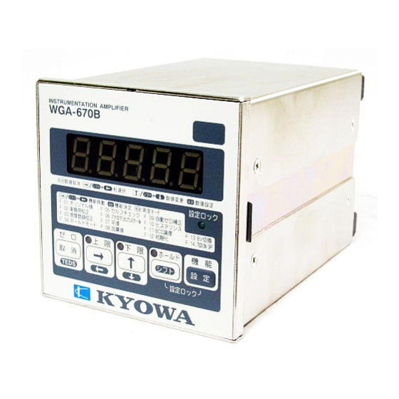
Page 9: Parts Names & Principal Functions
E) [LOW] Limit LED ....• Lights up when the measured value is less than the low limit value. • Flickers when low limit value is indicated. F) Operation Key ......• A pushbutton switch to operate the WGA-670B. For operation, see “4 OPERATION & FUNCTIONS.”... -
Page 10: Rear Panel
Nos. 19 & 20: LINE IN. Connect AC power supply. Nos. 10 & 11: Spare terminals. No connection Nos. 21 & 22: TEDS signal connection terminals. 21: TEDS(+), 22: TEDS(COM) C) Fitting Metal ......• Fitting metal for fixing the WGA-670B to the panel. -
Page 11: Connection
2. CONNECTION 2-1 INSTALLING TO PANEL To install the WGA-670B to a panel, prepare the panel according Panel cut dimensions to the specified panel cut dimensions as shown at the right. Then, install theWGA-670B by referring to the following instructions. -
Page 12: Connecting Control Input Terminal
2-2-4 Connecting Control Input Terminal • Contact connection terminal is as follows. Internal Internal Exte rnal Exte rnal No. 6: Common terminal (COMMON) No. 7: Reset No. 8: Hold No. 9: ZERO • For using the external switches; ZERO, HOLD, and RESET, 1〜... -
Page 13: Connecting Bcd Output (Wga-670B-1)
2-2-7 Connecting BCD Output (WGA-670B-1) • See “6. BCD OUTPUT OPTION.” 2-2-8 Connecting RS Output (WGA-670B-7) • See “7. RS-232C OPTION.” 2-2-9 Connecting TEDS Signal (WGA-670B-7) • See “8. TEDS OPTION.”... -
Page 14: Basic Operation Flow
3. BASIC OPERATION FLOW Procedures for operating the WGA-670B are roughly described in the following. For details, see “4. OPERATION & FUNCTIONS.” Item Outline of Operation Power ON and the WGA-670B is in measuring mode. (1) Power ON (See “4-1-1 Key Operation in Measuring Mode (Setting [LOCK])”... -
Page 15: Operation & Function
• Power ON the WGA-670B and the measuring mode is activated in [LOCK] state. • In the measuring mode, the WGA-670B measures load, pressure, torque, displacement and other physical quantities by combining with a strain gage type transducer and indicates the measured values on the indicator. -
Page 16: Key Operation In Function Selecting Mode
4-1-2 Key Operation in Function Selecting Mode • Press the FUNCTION key for 2 seconds in the measuring mode to activate the function selecting mode. At this time, function ‘F-01’ is indicated on the indicator. • By pressing the → key or SHIFT + ← keys in the function selecting mode, various functions are selected from ‘F-01’... -
Page 17: Function
F-07: Smoothing F-14: TEDS ON/OFF • For details of each function, see the following Table 4-2-1. Table 4-2-1 Various Functions in Function Selecting Mode Function Key Operation & WGA-670B Functional Function Name Selecting Mode Movement in Function Setting Mode Description... - Page 18 Function Key operation & WGA-670B Functional Function Name Selecting Mode Movement in Function Setting Mode Description F-02 Actual Load ●The indication ‘00628’ or ‘11111’ is a Calibration key code to prevent calibration value from carelessly changing due to malfunction. F-03...
- Page 19 Function Key Operation & WGA-670B Functional Function Name Selecting Mode Movement in Function Setting Mode Description F-04 Hold Mode Indicates the following items (1), (2), and •Sets various Hold (3). functions. (1) Setting Hold mode •For details, see 0 : Tracking “4-2-5.”...
- Page 20 Function Key Operation & WGA-670B Functional Function Name Selecting Mode Movement in Function Setting Mode Description •A function that F-07 Smoothing Indicates the following items (1), (2), and stables the (3). indication by smoothing (1) Number of (2)Minimum Scale varying signals...
- Page 21 Function Key Operation & WGA-670B Functional Function Name Selecting Mode Movement in Function Setting Mode Description F-09 Automatic ZERO Set ZERO compensation range and press •ZERO Compensation the SET key. compensation Next, set the determination time and range and press the SET key.
- Page 22 Function Key Operation & WGA-670B Functional Selecting Mode Function Name Movement in Function Setting Mode Descriptio Initialize F-12 •Key code enable setting • A ‘00000’ is indicated. function Here, set the indication to read ‘00628’ or ‘11111’ that and press the SET key. The following set values returns return to the factory default state.
- Page 23 Function Key Operation & WGA-670B Functional Function Name Selecting Mode Movement in Function Setting Mode Description BV set value 0: 10 V F-13 BV Select •A function that 1: 2 V selects bridge exciter voltage. Select either of the two and press the SET •It is set to 1(2 V)
-
Page 24: Digital Zero Function
4-2-2 Digital ZERO Function Digital ZERO function is a function that decides the reference point of the indicator. It is as same as setting the scale needle to ‘0’ position. There are 2 methods for deciding the reference point (ZERO), by key operation and by operation of contact input from the rear panel. -
Page 25: Setting High/Low Comparator & Hysteresis
4-2-3 Setting High/Low Comparator & Hysteresis High/low limit comparator and hysteresis function serve to compare the indicated value with the set value and outputs the compared results. The result of comparison is obtained as open collector output from the rear terminal board and indicated on the [HIGH]/[LOW] LED on the front panel. -
Page 26: Sensitivity Registering Calibration Function
4-2-4 Sensitivity Registering Calibration Function Sensitivity registering calibration function is a function that conducts calibration by registering the rated output of the transducer without applying the actual load. Description shall be made with an example when ‘1.000’ is indicated by applying 1 kN of load using a transducer having rated capacity of 1 kN and rated output of 2.004 mV/V. -
Page 27: Hold Function
→ Cancels the hold state. (Reset) (2) Operation From The Rear Panel • Short-circuit between terminal Nos. Nos. 6 and 8 (Hold) on the rear face and the WGA-670B moves with the preset hold mode. • Short-circuit between terminal Nos. 6 and 7 (RESET) on the rear face and the hold mode is canceled. - Page 28 4-2-5-1 Arbitrary Point Hold Mode • Press the HOLD key and after the lapse of delay time, the indication is kept hold until it is pressed the next time. • Or, when the [HOLD] signal from the rear terminal board is turned ON (close) and after the lapse of delay time, the indication is kept hold until the [HOLD] is signal is turned OFF.
- Page 29 4-2-5-3 Block Specified Peak Hold Mode a) For normal display mode • Press the HOLD key and after the lapse of delay time, the peak value is indicated. Press the HOLD key the 2nd time and the peak value is kept hold. Press the HOLD key the 3rd time and the peak hold mode is canceled.
- Page 30 Hold display mode • Press the HOLD key and the indication of that time is kept hold. After the lapse of delay time, although it is not shown on the indicator, the WGA-670B is in peak value detecting state.
- Page 31 4-2-5-4 Time Specified Peak Hold Mode a) Normal display mode • Press the HOLD key and after the lapse of delay time, the peak value is detected and kept hold for the preset specified time. Press the HOLD key the 2nd time and the peak hold mode is canceled. •...
- Page 32 b) Hold Display Mode • Press the HOLD key and the indicated value is kept hold. After the lapse of delay time, the peak value is detected and indicated for the preset specified time. Press the HOLD key the 2nd time and the hold display mode is canceled. •...
-
Page 33: Operation Timing
5. OPERATION TIMING 5-1 CONTROL INPUT (HOLD, RESET, ZERO) Cancels Cancels Starts Starts digital ZERO digital ZERO digital ZERO digital ZERO Starts Starts Starts Cancels Cancels operation operation operation operation the hold operation the hold operation the hold operation the hold operation the hold operation Operating Status Operating Status... -
Page 34: High/Low Limit Comparator Output
5-2 HIGH/LOW LIMIT COMPARATOR OUTPUT Higher limit Higher limit Hysteresis Hysteresis Hysteresis Hysteresis Lower limit Lower limit Input Signal Input Signal Higher limit output Higher limit output Lower limit output Lower limit output T1: 4ms(Max) ...... A delay time required, starting from the time when the input value exceeds the high limit comparative value preset on the comparator until the high limit output becomes ON. -
Page 35: Bcd Output Option
6. BCD OUTPUT OPTION 6-1 OUTLINE By installing the BCD interface to the WGA-670B-1, indicated values can be acquired as a BCD coded data. In addition, by connecting to a sequencer, printer, etc., various processing items such as data control and data recording are conducted with ease. -
Page 36: Setting Bcd Output
6-3 SETTING BCD OUTPUT The number of output times, data logic, and EOC logic are set with the function selecting mode ‘F-11.’ Since the hold input and output prohibit input are set to negative logic, no change is allowed. ‘F-11’ indication: (1) Output times – (2) Data logic – (3) EOC logic (1) Setting the Number of Output Times The first numeric value (1) indicated with the function selecting mode ‘F-11’... -
Page 37: Signal Timing
6-5 SIGNAL TIMING Signal operation timing is described in the following figure. To read data by EOC (End of Conversion), when it is set to negative logic, read BCD data, polarity data, and over data within 4ms from rising (positive) edge (when it is changed from “L” to “H”). To read data after conducting BCD data hold, set the data hold input to “L”... -
Page 38: Rs-232C Option
7. RS-232C OPTION 7-1 OUTLINE With the WGA-670B-7 (Equipped with TEDS interface + RS-232C interface), various functions can be set and measured values can be read from external devices. 7-2 RS-232C INTERFACE This section describes details of the RS-232C interface. - Page 39 (3) Connecting to External Devices a) Connection cable For connecting the WGA-670B to the PC, etc., use a commercially available RS cross cable (reverse type). (For reference, KRS-DOSV9C07K, KRS-403XFO7K, etc.: SANWA SUPPLY LTD. made) WGA side PC side (Note) Do not forget to power OFF both WGA-670B and the external devices before connection.
-
Page 40: Outline Of Control Command
7-3 OUTLINE of CONTROL COMMAND This section describes format and types of control commands issued from the PC to the WGA-670B. (1) Control Command Code • Command is in ASCII code with 3 characters. • Attached with parameters according to command characteristics. - Page 41 (2) List of Control Commands Type Contents Command Page Reads the measured value. Reads the status. Reading Reads various set values. Monitors the original value. Hold function Hold reset function Measurement Auto-ZERO function ZAD* Self check function Actual load calibration Sensitivity registering calibration Automatic sensitivity registration with TEDS Sets hold mode.
-
Page 42: Details Of Various Control Commands
(3) [SYS] Contents: Outputs Model name, etc. Format: SYS<CR> Parameter: None Return value format: WGA-670B-a,xx.xx,yyyyyyyyy<CR><LF> Production No. Program version Model Description & others: Details of the return value ‘a’ is as follows. 0: No option 1: BCD option 7: RS-232C+TEDS option... - Page 43 • Assume that it is operated in the Mode 00. If the Mode 02 is specified, the following message is sent back. ng<CR><LF> c) Mode 10 return value format Mode 10 operates the WGA-670B according to contents of the control commands. ok<CR><LF>...
- Page 44 (5) [/M] Contents: Writes the settings to non-volatile memory. Format: ********/M<CR> Corresponding command Description & others: Add ‘/M<CR>’ at the end of the determined command. Then, it is stored in the non-volatile memory. If the power is turned OFF, the contents determined without this command shall return to the original setting.
- Page 45 (8) [PRR] Contents: Outputs set value. Format: PRRppp<CR> Parameter: 010: Sensitivity registering value 020: Smoothing 030: Additional value 050: Hysteresis set value 051: Comparator H set value 052: Comparator L set value 053: Spare 054: Spare 070: Hold mode 090: Auto-ZERO compensation set value 100: Option Return value format: a) Return value of sensitivity registering value...
- Page 46 f) Return value of hold mode a, b, c,x.xx,yy.yy<CR><LF> Specified (second) Delay time (second) Comparison mode Display mode Hold mode • See SMF command. g) Return value of auto-ZERO compensation set value xxxxxx,y.y.z<CR><LF> ZERO near ZERO range Definition time Indicates ZERO range and indicated value with a decimal point. If the indicated value has no decimal point, it is filled with ‘0’...
- Page 47 (11) [EIC] Contents: Conducts sensitivity registering calibration. (Relevant to panel operation F-03) Format: EIC0x.xxx, ±yyyyyy<CR> Parameter: 0x.xxx, ±yyyyyy Indicates the indicated value with a decimal point. If the indicated value has no decimal point, it is filled with ‘0’ from the head. Sensor rated output value (mV/V) Return value format: ok<CR><LF>...
- Page 48 (14) [SSM] Contents: Set smoothing, moving average and minimum resolution. (Relevant to panel operation F-07.) Format: SSM3a00, b, c<CR> Parameter: 3a00, b, c Analog filter Minimum Resolution 0: 100 Hz Moving Average 0: 1 1: 10 Hz 0: None 1: 2 1: 8 times 2: 5 2: 16 times...
- Page 49 (17) [OP1] Contents: Set analog output (A/D output). (Relevant to panel operation F-06.) Format: OP1020, ±xxxxxx,±yyyyyy<CR> Parameter: ±xxxxxx,±yyyyyy Indicated value at 10 volts output Indicated value at 0 volt output. • Both indicated values include decimal point. If the indicated value has no decimal point, it is filled with ‘0’...
- Page 50 (20) [LCK] Contents: Set keylock Format: LCKa<CR> Parameter: 0: Cancels keylock 1: Sets keylock Return value format: ok<CR><LF> Description & others: This command becomes disabled with the power OFF. (21) [ZAD] Contents: Auto-ZERO function Format: ZAD<CR> Parameter: None Return value format: ok<CR><LF>...
-
Page 51: Teds Option
8. TEDS OPTION 8-1 OUTLINE By connecting the TEDS (Transducer Electronic Data Sheet) built-in sensors to the WGA-670B-7, the most appropriate sensitivity registration is automatically available. Connecting up to 4 sensors of the same standard is available. 8-2 CONNECTION Connect TEDS signal sensors to the following terminal boards Nos. 21 and 22 on the rear panel as shown in the following figure. -
Page 52: Operation
8-3 OPERATION There are 3 methods for automatically registering sensitivity by reading the sensor information. One is to automatically register the sensitivity with the power ON. The second is to register the sensitivity by panel key operation. And the third is to send command from the PC that is connected to RS-232C port. Operations of the respective methods are described in the following. - Page 53 (3) Automatic sensitivity registration by receiving command By connecting the WGA-670B to the PC using RS-232C interface, the automatic sensitivity registration command is received via RS-232C interface from the PC For details of PC connection, see “7. RS-232C OPTION.” The command of the automatic sensitivity registration is described in the following.
-
Page 54: Specifications
9. SPECIFICATIONS 9-1 SPECIFICATIONS Model Name ........WGA-670B Number of Measuring channels ..1 Applicable Transducer ......Strain Gage Transducer Applicable Bridge Resistance ..... 87.5 Ω to 10 kΩ (350 Ω connecting four WGA-670Bs in parallel) Bridge Exciter ........10 VDC, 2 VDC Measuring Range .......±3.2 mV/V (In gross weight) - Page 55 Power Supply ........100 to 240 VAC ±10% 50/60Hz single phase, 20 VA or less Dimensions ........96(W) × 96(H )× 139(D) (Protruded portion not included) Weight ..........Approximately 1.1kg (WGA-670B-0) Notation ..........English or Japanese EMC Standard ........EN61326-1 (Class A) Safety Standard ........EN61010-1 (Installation category: II, Pollution degree: 2)
-
Page 56: Outside Drawing
9-2 OUTSIDE DRAWING (1) With No Option (WGA-670B-0) - Page 57 (2) With BCD Option (WGA-670B-1)
- Page 58 (3) With RS+TEDS Option (WGA-670B-7)
-
Page 59: Error Code List
Contents Countermeasures 0FL1 Measured value is exceeding the measuring range to the minus side. Decrease the input signal. Use the WGA-670B within measuring range of ±3.2 mV/V. 0FL2 Measured value is exceeding the measuring range to the plus side. 0FL3 Indicated value is below -19999. - Page 60 Artisan Technology Group is your source for quality new and certified-used/pre-owned equipment SERVICE CENTER REPAIRS WE BUY USED EQUIPMENT • FAST SHIPPING AND DELIVERY Experienced engineers and technicians on staff Sell your excess, underutilized, and idle used equipment at our full-service, in-house repair center We also offer credit for buy-backs and trade-ins •...
Need help?
Do you have a question about the WGA-670B and is the answer not in the manual?
Questions and answers