Sign In
Upload
Manuals
Brands
Allied Telesis Manuals
Switch
x950-28XTQm
Allied Telesis x950-28XTQm Manuals
Manuals and User Guides for Allied Telesis x950-28XTQm. We have
4
Allied Telesis x950-28XTQm manuals available for free PDF download: Installation Manual
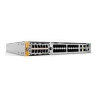
Allied Telesis x950-28XTQm Installation Manual (280 pages)
Advanced Layer 3+, AlliedWare Plus v5.5.0-1
Brand:
Allied Telesis
| Category:
Switch
| Size: 25.62 MB
Table of Contents
Table of Contents
5
Preface
15
Document Conventions
16
Contacting Allied Telesis
17
Chapter 1: Overview
20
X950 Switches
20
Figure 1: Front Panels of the X950 Switches
20
Figure 2: Rear Panel of the X950 Switches
21
Features
22
Hardware Features
22
XEM2 Ethernet Line Cards
22
Management Software and Interfaces
23
Management Methods
23
Management Panel
23
Power Supplies
24
Ports for 1/2.5/5/10Gbps SFP/SFP+ Transceivers
25
SFP and SFP+ Transceivers
25
Leds
26
Figure 3: Link and Activity Leds for Ports for 1/2.5/5/10Gbps SFP/SFP+ Transceivers
26
Table 1: Link and Activity Status Leds for Ports for 1/2.5/5/10Gbps SFP/SFP+ Transceivers
26
Ports 1 to 24 on the X950-28Xtqm Switch
27
Cable Requirements
27
Table 2: Twisted Pair Ports 1 to 24 on the X950-28Xtqm Switch
27
Leds
28
Figure 4: Link and Activity Leds for Ports 1 to 24 on the X950-28Xtqm Switch
28
Table 3: Link and Activity Leds for Ports 1 to 24 on the X950-28Xtqm Switch
28
Ports for 40Gbps QSFP+ or 100Gbps QSFP28 Transceiver, or Breakout Cables
29
QSFP28 Transceivers
29
QSFP+ Transceivers
29
Breakout Cables
29
Table 4: Ports for QSFP
29
Leds
30
Figure 5: QSFP-4SFP10G-3CU or QSFP-4SFP10G-5CU Copper Breakout Cable
30
Figure 6: ET3-MPO08-4LC-5 or ET3-MPO08-4LC-10 Fiber Optic Breakout Cable
30
Figure 7: Leds for Ports 25, 29, 33, 37 on the X950-28XSQ and X950-28Xtqm Switches
30
Figure 8: Leds for Ports 49, 53, 57, 61 on X950-52XSQ Switch
31
Table 5: Link and Activity Status Leds for 40Gbps QSFP+ or 100Gbps QSFP28 Transceivers
31
Port Numbering for the X950-28XSQ and X950-28Xtqm Switches
32
Table 6: Link and Activity Status Leds for 10Gbps Breakout Cables
32
Port Numbering for the X950-52XSQ Switch
33
Table 7: Port Numbering for Ports 25 to 37
33
Table 8: Port Numbering for Ports 49, 53, 57, and 61
33
Management Panel
34
Figure 10: Management Panel for the X950-52XSQ Switch
34
Figure 9: Management Panel for the X950-28XSQ and X950-28Xtqm Switches
34
NET MGMT Ethernet Management Port
35
USB Port
35
Console (RS-232) Port
36
Switch ID LED
36
Table 9: NET MGMT Port LED
36
Figure 11: Switch ID LED with the Eco-Friendly Mode Disabled
37
Figure 12: Switch ID LED with the Eco-Friendly Mode Enabled
37
Eco-Friendly Button
38
Optional Direct Attach Cables
39
Table 10: Optional Direct Attach Cables
39
PWR600 AC and DC Power Supplies
40
PWR600 AC Power Supply
41
Figure 13: PWR600 AC Power Supply
41
Leds
42
Table 11: Leds on the PWR600 AC Power Supply
42
PWR600 DC Power Supply
43
Leds
43
Figure 14: PWR600 DC Power Supply
43
Figure 15: Leds for PWR600 DC Power Supply
43
Table 12: Leds on the PWR600 DC Power Supply
43
FAN05 Cooling Fan
45
Figure 16: FAN05 Fan Module
45
Designating Ports in the Command Line Interface
46
Figure 17: PORT Parameter in the Command Line Interface
46
Table 13: PORT Parameter Format
46
Examples of Port Numbering
47
Figure 18: Slot Numbers for Port Numbering
47
Software and Hardware Releases
49
Table 14: Software and Hardware Releases
49
Chapter 2: XEM2 Ethernet Line Cards
51
Overview
52
Figure 19: XEM2 Ethernet Line Cards
52
Table 15: XEM2 Ethernet Line Cards
53
XEM2-8Xstm Line Card
55
Twisted Pair Ports
55
Figure 20: XEM2-8Xstm Line Card
55
Table 16: Twisted Pair Ports on the XEM2-8Xstm Line Card
55
Twisted Pair Port Leds
56
Table 17: Link and Activity Leds for the Twisted Pair Ports on the XEM2-8Xstm Line Card
56
Transceivers Ports
57
Transceivers Port Leds
57
Table 18: Link and Activity Leds for the SFP Ports on the XEM2-8Xstm Line Card
57
XEM2-12XT Line Card
59
Twisted Pair Ports
59
Figure 21: XEM2-12XT Line Card
59
Table 19: Twisted Pair Ports on the XEM2-12XT Line Card
59
Leds
60
Table 20: Port Link and Activity Leds on the XEM2-12XT Line Card
60
XEM2-12Xtm Line Card
61
Twisted Pair Ports
61
Figure 22: XEM2-12Xtm Line Card
61
Table 21: Twisted Pair Ports on the XEM2-12Xtm Line Card
61
Leds
62
Table 22: Link and Activity Leds on the XEM2-12Xtm Line Card
62
XEM2-12XS and XEM2-12XS V2 Line Cards
63
Transceiver Ports
63
Figure 23: XEM2-12XS Line Card
63
Card Versions
64
Leds
64
Figure 24: XEM2-12XS and XEM2-12XS V2 Line Cards
64
Table 23: Port Link and Activity Leds on the XEM2-12XS Line Card
64
XEM2-4QS Line Card
66
Transceiver Ports
66
Figure 25: XEM2-4QS Line Card
66
Leds
67
Table 24: Port Link and Activity Status Leds on the XEM2-4QS Line Card
67
Table 25: Link and Activity Status Leds for 10Gbps Breakout Cables
67
XEM2-1CQ Line Card
68
Transceiver Port
68
Led
68
Figure 26: XEM2-1CQ Line Card
68
Table 26: Port Link and Activity Status LED on the XEM2-1CQ Line Card
68
Chapter 3: Virtual Chassis Stacking
71
Overview
72
Stacking Guidelines
73
Stack Trunks
74
Ports 1 to 24 and Ports 1 to 48
74
Figure 27: Example Stacks of X950-28XSQ Switches with Trunks of 10Gbps Ports
76
Figure 28: Example Stacks of X950-28Xtqm Switches with Trunks of 10Gbps Ports
77
Figure 29: Example Stack Trunks of 10Gbps Links on X950-28XSQ and X950-52XSQ Switches
78
Ports 25 to 37 and Ports 49 to 61 with 40Gbps Transceivers
79
Figure 30: Stack Trunk Examples of Two Switches with Trunk 40Gbps Links
79
Ports 25 to 37 and Ports 49 to 61 with 100Gbps Transceivers
80
Figure 31: Stack Trunk Examples of Three or Four Switches with 40Gbps Links
80
Figure 32: Stack Trunk Examples with 100Gbps Links
81
XEM2 Line Cards
82
Table 27: Maximum Number of Trunk Ports Per Switch
82
Figure 33: Example Trunk Using XEM2-12XT Line Cards
83
Figure 34: Example Trunk Using XEM2-12XS Line Cards
83
Unsupported Trunks
84
Figure 35: Example Trunk Using XEM2-4QS Line Cards
84
Figure 36: Unsupported Trunk with Different Numbers of Links between Switches
84
Figure 37: Unsupported Trunk with Mixed Cables
85
Figure 38: Unsupported Trunk with both Base and XEM2 Line Card Ports
85
Figure 39: Unsupported Trunk of Connected Base and Line Card Ports
85
Figure 40: Unsupported Trunk with Only One Link between Switches
86
Figure 41: Unsupported Trunk with Different Port Speeds
86
Figure 42: Not Recommended Stack Trunk of XEM2-1CQ Line Cards
87
Figure 43: Unsupported Trunk with a 10Gbps Breakout Cable
87
Figure 44: Unsupported Trunk with Intermediary Network Devices
88
Master and Member Switches
89
Selection of the Master Switch
89
Switch ID Numbers
90
Optional Feature Licenses
91
Planning a Stack
92
Stacking Worksheet
93
Table 28: Stacking Worksheet
93
Table 29: Stacking Worksheet Columns
94
Table 30: Example of a Completed Stack Worksheet
96
Chapter 4: Beginning the Installation
97
Reviewing Safety Precautions
98
Installation Options
103
Figure 45: Installation Options
103
Choosing a Site for the Chassis
104
Unpacking the Switch
105
Figure 46: Removing Accessories
105
Figure 47: Removing the Shipping Partition
106
Figure 48: Lifting the Switch from the Shipping Box
107
Figure 49: Removing the Switch from the Shipping End-Caps and Protective Bag
107
Verifying the Accessory Kit
109
Figure 50: Accessory Kit
109
Unpacking the PWR600 AC Power Supply
111
Figure 51: Removing the Power Cord and Documents from the PWR600 AC Power Supply
111
Figure 52: Removing the Partition from the PWR600 AC Power Supply Shipping Box
112
Figure 53: Removing the Power Supply from the Shipping Box
113
Figure 54: Removing the Power Supply from the Shipping End-Caps and Protective Bag
113
Unpacking the PWR600 DC Power Supply
114
Chapter 5: Installing Power Supplies and Optional XEM2 Line Card
115
Installing PWR600 AC Power Supplies
116
Figure 55: Removing the Blank Power Supply Panel from Slot PSU B
117
Figure 56: Sliding the PWR600 AC Power Supply into the Switch
118
Figure 57: Seating the Power Supply on the Internal Connector
119
Installing PWR600 DC Power Supplies
120
Figure 58: Sliding the PWR600 DC Power Supply into the Chassis
121
Connecting the Grounding Wire
123
Figure 59: Stripping the Grounding Wire
123
Figure 60: Loosening the Screw for the Panel
124
Figure 61: Accessing the Connectors
124
Figure 62: Loosening the Ground Screw
125
Figure 63: Wrapping the Grounding Wire and Tightening the Screw
125
Connecting the DC Power Wires
126
Figure 64: Stripping the Power Wire
126
Figure 65: Wrapping the Wire Strands
126
Figure 66. Loosening the Screw for the Negative
127
Figure 67. Tightening the Screw for the Negative
127
Figure 68: Loosening the Screw for the Negative (+)
128
Figure 69: Tightening the Screw for the Negative (+)
128
Figure 70: Placing the Cover Panel
129
Figure 71: Tightening the Screw for the Cover Panel
129
Installing an Optional XEM2 Ethernet Line Card
130
Figure 72: Removing the Blank Line Card Cover
130
Figure 73: Removing the Ethernet Line Card from the Anti-Static Bag
131
Figure 74: Sliding the Ethernet Line Card into the Slot
131
Figure 75: Seating the Ethernet Line Card in the Expansion Slot
132
Figure 76: Tightening the Two Captive Screws on the Ethernet Line Card
133
Chapter 6: Installing the Switch on a Table
135
Figure 77: Parts of the Bumper Feet
135
Figure 78: Holes for Bumper Feet
136
Figure 79: Inserting the Rivet Housing into the Bumper Foot
136
Figure 80: Placing the Bumper Foot on a Base Corner Hole
137
Figure 81: Inserting the Rivet into the Bumper Foot
137
Chapter 7: Installing the Switch in an Equipment Rack
139
Beginning the Installation
140
Required Items
140
Switch Orientations in the Equipment Rack
140
Figure 82: Bracket Holes on the Switch
140
Figure 83: Switch Orientations in an Equipment Rack
141
Removing the Bumper Feet
142
Figure 84: Removing the Bumper Feet
142
Installing the Switch
143
Figure 85: Attaching the Equipment Rack Brackets
144
Figure 86: Installing the Switch in an Equipment Rack
144
Chapter 8: Installing the Switch on a Wall
147
Switch Orientations on a Wall
148
Figure 87: Positions of the Switch on the Wall
148
Recommended Minimum Wall Area Dimensions
149
Figure 88: Minimum Wall Area Dimensions with the Front Panel on the Left
149
Figure 89: Minimum Wall Area Dimensions with the Front Panel on the Right
150
Plywood Base for a Wall with Wooden Studs
151
Figure 90: Switch on the Wall with a Plywood Base
151
Figure 91: Steps to Installing the Switch with a Plywood Base
152
Installation Guidelines
153
Tools and Material
153
Installing the Plywood Base
155
Installing the Switch on the Plywood Base
156
Figure 92: Installing the Brackets to the Switch for Wall Installation
156
Figure 93: Attaching the Switch to the Plywood Base
157
Installing the Switch on a Concrete Wall
159
Figure 94: Marking the Locations of the Bracket Holes on a Concrete Wall
160
Figure 95: Installing the Switch on a Concrete Wall
161
Chapter 9: Installing the Switch in the RKMT-SL01 Sliding Rack
163
Introduction
164
Rack Mount Kit Components
165
Adjustable Outer Rails
165
Inner Rails
165
Extension Brackets
165
Figure 96: Outer Rails
165
Figure 97: Inner Rails
165
Figure 98: Extension Brackets
166
Equipment Rack Requirements
167
Reviewing Safety Precautions
168
Installation Overview
171
Unpacking the Shipping Container
172
Figure 99: Shipping Container Contents
172
Installing the Outer Rails on the Equipment Rack
174
Figure 100: FRONT and REAR Labels on the Outer Rails
174
Figure 101: Installing the Outer Rails on the Equipment Rack
175
Installing the Extension Brackets on the Inner Rails
176
Measuring the Extension Bracket Lengths
176
Figure 102: Extension Brackets
176
Figure 103: Example of a Switch Recessed in an Equipment Rack
176
Figure 104: Inserting an Inner Rail into an Outer Rail
177
Figure 105: Example of Positioning the Inner Rail
177
Figure 106: Measuring for the Extension Brackets
177
Assembling the Extension Brackets
178
Figure 107: Removing the Inner Rail
178
Figure 108: Extension Bracket Parts
178
Table 31: Extension Bracket Parts
178
Figure 109: Extension Bracket Configurations
179
Figure 110: Example of Attaching the Extension Brackets to the Inner Rails
180
Figure 111: Testing the Inner Rails with the Extension Brackets
181
Figure 112: Verifying the Length of the Extension Bracket
181
Installing the Inner Rails on the Switch
182
Figure 113: Inner Rail Screw Holes for the X950-28XSQ and X950-28Xtqm Switches
182
Figure 114: Inner Rail Screw Holes for the X950 Switch
182
Figure 115: Attaching the Inner Rails to the X950 Switch
183
Installing the Switch in the Equipment Rack
184
Figure 116: Sliding the Inner Rails on the Switch into the Outer Rails
184
Figure 117: Affixing the Warning Labels
185
Figure 118: Tightening the Two Screws on the Fixed Brackets
185
Figure 119: Tightening the Screws on the Outer Rails
186
Chapter 10: Configuring the Master Switch
187
Command Summary
188
Platform Portmode Interface
188
Stackport
189
Stack Enable
189
Stack Priority
190
Stack Renumber
190
Switch Provision
190
Powering on a Switch
192
Powering on the PWR600 AC Power Supply
192
Figure 120: Connecting the AC Power Cord
192
Figure 121: Securing the Power Cord with the Restraining Strap
193
Powering on the PWR600 DC Power Supply
194
Figure 122: Connecting the Power Cord to an AC Power Source
194
Starting a Local Management Session
196
Figure 123: Connecting the Management Cable to the Console RS-232 Port
196
Figure 124: User Exec Mode Prompt
197
General Steps for the Master Switch
198
Configuring the Master Switch - Part I
200
Table 32: Configuring the Master Switch - Part I
200
Configuring the Master Switch - Part II
203
Table 33: Configuring the Master Switch- Part II
204
Verifying the Master Switch
206
Table 34: Verifying the Master Switch
206
What to Do Next
208
Figure 125: Powering off the AC Power Supply
208
Chapter 11: Configuring Member Switches
209
General Steps for Member Switches
210
Configuring a Member Switch - Part I
212
Table 35: Configuring a Member Switch - Part I
212
Configuring a Member Switch - Part II
215
Table 36: Configuring a Member Switch - Part II
216
Verifying a Member Switch
218
Table 37: Verifying a Member Switch
218
What to Do Next
220
Chapter 12: Powering on and Verifying the Stack
221
Powering on the Stack
222
Verifying the Stack
223
Figure 126: SHOW STACK Command
223
Chapter 13: Cabling the Networking Ports
225
Cabling Twisted Pair Ports
226
Guidelines to Handling Twisted Pair or Fiber Optic Transceivers
227
Figure 127: Handle on 100Gbps Transceivers for XEM2-1CQ Line Cards
227
Installing Transceivers
228
Table 38: Transceivers for the Base Transceiver Slots
228
Figure 128: SP10T Transceivers
229
Table 39: Transceivers for XEM2 Ethernet Line Cards
229
Figure 129: Installing an SFP or SFP+ Transceiver
232
Figure 130: Installing 40Gbps Fiber Optic Transceivers in XEM2-4QS Line Cards
232
Figure 131: Installing 100Gbps QSFP28 Transceivers in Base Ports 25, 29, 33, 37
233
Figure 132: Installing 100Gbps QSFP28 Transceivers in XEM2-1CQ Line Cards
233
Installing Direct Attach Cables
235
Figure 133: Installing SP10TW Direct Attach Cables
235
Figure 134: Attaching QSFPCU Cables
236
Chapter 14: Replacing Modules
237
Replacing XEM2 Ethernet Line Cards
238
Figure 135: Loosening the Screws on the Ethernet Line Card
239
Figure 136: Disconnecting an Ethernet Line Card from the Switch
240
Figure 137: Sliding an Ethernet Line Card from the Switch
240
Figure 138: Placing the Ethernet Line Card in Its Anti-Static Bag
241
Figure 139: Installing the Line Card Blank Cover
241
Figure 140: Tightening the Two Screws on the Line Card Blank Panel
242
Replacing PWR600 AC Power Supplies
243
Figure 141: Disconnecting the AC Power Cord from the Power Source
243
Figure 142: Opening the Restraining Strap on the Power Supply
244
Figure 143: Disconnecting the Power Cord from the Power Supply
244
Figure 144: Removing the Power Supply
245
Figure 145: Removing a Power Supply
246
Figure 146: Installing the Blank Power Supply Cover
247
Replacing PWR600 DC Power Supplies
248
Figure 147: Loosening the Screw for the Panel
248
Figure 148: Accessing the Connecting Screws
249
Figure 149: Front Panel of the PWR600 DC Power Supply
249
Figure 150: Front Panel of the PWR600 DC Power Supply
250
Replacing FAN05 Modules
251
Removing Fan Modules
251
Figure 151: Loosening the Screws on the Fan Module
251
Figure 152: Disconnecting the FAN05 Module from the Switch
252
Figure 153: Sliding the Fan Module from the Switch
252
Installing Fan Modules
253
Figure 154: Removing the Fan Module from the Shipping Container
253
Figure 155: Aligning the FAN05 Module in the Switch Slot
254
Figure 156: Seating the FAN05 Module on the Internal Connector
254
Figure 157: Tightening the Two Captive Screws on the FAN05 Module
255
Chapter 15: Troubleshooting
257
Appendix A: Technical Specifications
263
Physical Specifications
264
Figure 158: Switch Width and Height
264
Table 40: Product Dimensions
264
Figure 159: Switch Depth and Locations of Bracket Holes
265
Table 41: Product Weights
265
Table 42: Ventilation Requirements
266
Environmental Specifications
267
Table 43: Environmental Specifications
267
Power Specifications
268
Table 44: Maximum Power Consumptions (Watts) for the X950-28XSQ Switch
268
Table 45: Maximum Power Consumptions (Watts) for the X950-28Xtqm Switch
270
Table 46: Maximum Power Consumptions (Watts) for the X950-52XSQ Switch
271
Table 47: Typical Power Savings in Eco-Friendly Mode (Watts) for the X950-28XSQ Switch
272
Table 48: Typical Power Savings in Eco-Friendly Mode (Watts) for the X950-28Xtqm Switch
272
Table 49: Input Voltages
273
Table 50: Maximum Power Supply Efficiency (Based on 100V Input Voltage)
273
Table 51: Heat Dissipations for the X950-28XSQ Switch
273
Table 52: Heat Dissipations for the X950-28Xtqm Switch
275
Table 53: Heat Dissipations for the X950-52XSQ Switch
276
Certifications
277
Table 54: Product Certifications
277
Twisted Pair Port Pinouts
278
Figure 160: Pin Layout (Front View) of Twisted Pair Ports
278
Table 55: Pin Signals on RJ-45 Twisted Pair Ports at 100Mbps
278
Table 56: Pin Signals on Twisted Pair Ports at 1/2.5/5/10Gbps
279
Style Serial Console Port Pinouts
280
Table 57: RJ-45 Style Serial Console Port Pin Signals
280
Advertisement
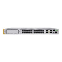
Allied Telesis x950-28XTQm Installation Manual (176 pages)
Stand-alone Switches
Brand:
Allied Telesis
| Category:
Switch
| Size: 9.17 MB
Table of Contents
Electrical Safety and Emissions Standards
3
Translated Safety Statements
4
Table of Contents
5
Preface
13
Document Conventions
14
Contacting Allied Telesis
15
Chapter 1: Overview
17
X950 Switches
18
Figure 1: Front Panels of the X950 Switches
18
Figure 2: Rear Panel of the X950 Switches
19
Features
20
Hardware Features
20
XEM2 Ethernet Line Cards
20
Management Software and Interfaces
21
Management Methods
21
Management Panel
21
Power Supplies
21
Ports 1 to 24 on the X950-28XSQ Switch
22
SFP and SFP+ Transceivers
22
Leds
23
Figure 3: Link and Activity Leds for Ports 1 to 24
23
Table 1: Link and Activity Status Leds for Ports 1 to 24
23
Ports 1 to 24 on the X950-28Xtqm Switch
24
Cable Requirements
24
Table 2: Twisted Pair Ports 1 to 24 on the X950-28Xtqm Switch
24
Leds
25
Figure 4: Link and Activity Leds for Ports 1 to 24 on the X950-28Xtqm Switch
25
Table 3: Link and Activity Leds for Ports 1 to 24 on the X950-28Xtqm Switch
25
Ports 25 to 37
26
QSFP28 Transceivers
26
QSFP+ Transceivers
26
Breakout Cables
26
Figure 5: QSFP-4SFP10G-3CU and QSFP-4SFP10G-5CU Copper Breakout Cables
26
Leds
27
Figure 6: ET3-MPO08-4LC-5 and ET3-MPO08-4LC-10 Fiber Optic Breakout Cables
27
Figure 7: Leds for Ports 25 to 37
27
Table 4: Link and Activity Status Leds for 40Gbps QSFP+ or 100Gbps QSFP28 Transceivers
27
Port Numbering
28
Table 5: Link and Activity Status Leds for 10Gbps Breakout Cables
28
Table 6: Port Numbering for Ports 25 to 37
29
Management Panel
30
USB Port
30
Figure 8: Management Panel
30
NET MGMT Ethernet Management Port
31
Table 7: NET MGMT Port LED
31
Console (RS-232) Port
32
Switch ID LED
32
Figure 9: Switch ID LED with the Eco-Friendly Mode Disabled
32
Eco-Friendly Button
33
Figure 10: Switch ID LED with the Eco-Friendly Mode Enabled
33
Optional Direct Attach Cables
34
Table 8: Optional Direct Attach Cables
34
PWR600 Power Supply
35
Figure 11: PWR600 Power Supply
35
Leds
36
Table 9: Leds on the PWR600 Power Supply
36
FAN05 Cooling Fan
37
Figure 12: FAN05 Fan Module
37
Designating Ports in the Command Line Interface
38
Figure 13: PORT Parameter in the Command Line Interface
38
Table 10: PORT Parameter Format
38
Figure 14: Slot Numbers for Port Numbering on Stand-Alone Switches
39
Software and Hardware Releases
40
Table 11: Software and Hardware Releases
40
Chapter 2: XEM2 Ethernet Line Cards
41
Overview
42
Figure 15: XEM2 Ethernet Line Cards
42
Table 12: XEM2 Ethernet Line Cards
43
XEM2-8Xstm Line Card
45
Twisted Pair Ports
45
Figure 16: XEM2-8Xstm Line Card
45
Table 13: Twisted Pair Ports on the XEM2-8Xstm Line Card
45
Twisted Pair Port Leds
46
Table 14: Link and Activity Leds for the Twisted Pair Ports on the XEM2-8Xstm Line Card
46
Transceiver Ports
47
Transceiver Port Leds
47
Table 15: Link and Activity Leds for the SFP Ports on the XEM2-8Xstm Line Card
47
XEM2-12XT Line Card
49
Twisted Pair Ports
49
Figure 17: XEM2-12XT Line Card
49
Table 16: Twisted Pair Ports on the XEM2-12XT Line Card
49
Leds
50
Table 17: Port Link and Activity Leds on the XEM2-12XT Line Card
50
XEM2-12Xtm Line Card
51
Twisted Pair Ports
51
Figure 18: XEM2-12Xtm Line Card
51
Table 18: Twisted Pair Ports on the XEM2-12Xtm Line Card
51
Leds
52
Table 19: Link and Activity Leds on the XEM2-12Xtm Line Card
52
XEM2-12XS Line Card
53
Transceiver Ports
53
Figure 19: XEM2-12XS Line Card
53
Leds
54
Table 20: Port Link and Activity Leds on the XEM2-12XS Line Card
54
XEM2-4QS Line Card
55
Transceiver Ports
55
Leds
55
Figure 20: XEM2-4QS Line Card
55
Table 21: Port Link and Activity Status Leds on the XEM2-4QS Line Card
56
Table 22: Link and Activity Status Leds for 10Gbps Breakout Cables
56
XEM2-1CQ Line Card
57
Transceiver Port
57
Leds
57
Figure 21: XEM2-1CQ Line Card
57
Table 23: Port Link and Activity Status LED on the XEM2-1CQ Line Card
57
Chapter 3: Beginning the Installation
59
Reviewing Safety Precautions
60
Installation Options
65
Figure 22: Installation Options
65
Choosing a Site for the Chassis
66
Unpacking the Switch
67
Figure 23: Removing Accessories
67
Figure 24: Removing the Shipping Box Partition
68
Figure 25: Lifting the Switch from the Shipping Box
69
Figure 26: Removing the Switch from the Shipping End-Caps and Protective Bag
69
Verifying the Accessory Kit
71
Figure 27: Accessory Kit
71
Unpacking the PWR600 AC Power Supply
73
Figure 28: Removing the Power Cord and Documents from the PWR600 AC Power Supply
73
Figure 29: Removing the Partition from the PWR600 AC Power Supply Shipping Box
74
Figure 30: Removing the Power Supply from the Shipping Box
75
Figure 31: Removing the Power Supply from the Shipping End-Caps and Protective Bag
75
Chapter 4: Installing Power Supplies and Optional XEM2 Line Card
77
Installing PWR600 AC Power Supplies
78
Figure 32: Removing the Blank Power Supply Panel from Slot PSU B
79
Figure 33: Sliding the PWR600 AC Power Supply into the Chassis
80
Figure 34: Seating the Power Supply on the Internal Connector
81
Installing an Optional XEM2 Ethernet Line Card
82
Figure 35: Removing the Blank Line Card Cover
82
Figure 36: Removing the Ethernet Line Card from the Anti-Static Bag
83
Figure 37: Sliding the Ethernet Line Card into the Slot
83
Figure 38: Seating the Ethernet Line Card in the Expansion Slot
84
Figure 39: Tightening the Two Captive Screws on the Ethernet Line Card
85
Chapter 5: Installing the Switch on a Table
87
Figure 40: Parts of the Bumper Feet
87
Figure 41: Holes for Bumper Feet
88
Figure 42: Inserting the Rivet Housing into the Bumper Foot
88
Figure 43: Placing the Bumper Foot on a Base Corner Hole
89
Figure 44: Inserting the Rivet into the Bumper Foot
89
Chapter 6: Installing the Switch in an Equipment Rack
91
Beginning the Installation
92
Required Items
92
Switch Orientations in the Equipment Rack
92
Figure 45: Bracket Holes on the Switch
92
Figure 46: Switch Orientations in an Equipment Rack
93
Removing the Bumper Feet
94
Figure 47: Removing the Bumper Feet
94
Installing the Switch
95
Figure 48: Attaching the Equipment Rack Brackets
96
Figure 49: Installing the Switch in an Equipment Rack
96
Chapter 7: Installing the Switch on a Wall
99
Switch Orientations on a Wall
100
Figure 50: Positions of the Switch on the Wall
100
Recommended Minimum Wall Area Dimensions
101
Figure 51: Minimum Wall Area Dimensions with the Front Panel on the Left
101
Figure 52: Minimum Wall Area Dimensions with the Front Panel on the Right
102
Plywood Base for a Wall with Wooden Studs
103
Figure 53: Switch on the Wall with a Plywood Base
103
Figure 54: Steps to Installing the Switch with a Plywood Base
104
Installation Guidelines
105
Tools and Material
105
Installing the Plywood Base
107
Installing the Switch on the Plywood Base
108
Figure 55: Installing the Brackets to the Switch for Wall Installation
108
Figure 56: Attaching the Switch to the Plywood Base
110
Installing the Switch on a Concrete Wall
111
Figure 57: Marking the Locations of the Bracket Holes on a Concrete Wall
112
Figure 58: Installing the Switch on a Concrete Wall
113
Chapter 8: Verifying and Configuring the Switch
115
Powering on the Switch
116
Figure 59: Connecting the AC Power Cord
117
Figure 60: Securing the Power Cord with the Restraining Strap
117
Figure 61: Connecting the Power Cord to an AC Power Source
118
Starting a Local Management Session
119
Figure 62: Connecting the Management Cable to the Console RS-232 Port
119
Figure 63: User Exec Mode Prompt
120
Verifying the Switch with Alliedware Plus Commands
121
Disabling Vcstack
122
Figure 64: SHOW STACK Command
122
Figure 65: Moving to the Global Configuration Mode
123
Figure 66: Confirmation Prompt for the no STACK ENABLE Command
123
Figure 67: Returning to the Privileged Exec Mode
123
Figure 68: Saving the Changes with the WRITE Command
124
Configuring Ports 25 to 37
125
Saving Your Changes and Rebooting the Switch
128
Figure 69: Returning to the Privileged Exec Mode
128
Figure 70: Saving the Changes with the WRITE Command
128
Chapter 9: Cabling the Networking Ports
129
Cabling Twisted Pair Ports
130
Guidelines to Handling Twisted Pair or Fiber Optic Transceivers
131
Figure 71: Handle on 100Gbps Transceivers for XEM2-1CQ Line Cards
131
Installing Transceivers
132
Table 24: Transceivers for the Base Transceiver Slots
132
Figure 72: SP10T Transceivers
133
Table 25: Transceivers for the Optional XEM2 Ethernet Line Cards
133
Figure 73: Installing an SFP or SFP+ Transceiver
135
Figure 74: Installing 40Gbps Fiber Optic Transceivers in XEM2-4QS Line Cards
136
Figure 75: Installing 100Gbps QSFP28 Transceivers in Base Ports 25 to 37
136
Figure 76: Installing 100Gbps QSFP28 Transceivers in XEM2-1CQ Line Cards
137
Installing Direct Attach Cables
138
Figure 77: Installing SP10TW Direct Attach Cables
138
Figure 78: Attaching QSFPCU Cables
139
Chapter 10: Replacing Modules
141
Replacing XEM2 Ethernet Line Cards
142
Figure 79: Loosening the Screws on the Ethernet Line Card
143
Figure 80: Disconnecting an Ethernet Line Card from the Switch
144
Figure 81: Sliding an Ethernet Line Card from the Switch
144
Figure 82: Placing the Ethernet Line Card in Its Anti-Static Bag
145
Figure 83: Installing the Line Card Blank Cover
145
Figure 84: Tightening the Two Screws on the Line Card Blank Panel
146
Replacing PWR600 AC Power Supplies
147
Figure 85: Disconnecting the AC Power Cord from the Power Source
147
Figure 86: Opening the Restraining Strap on the Power Supply
148
Figure 87: Disconnecting the Power Cord from the Power Supply
148
Figure 88: Removing the Power Supply
149
Figure 89: Removing a Power Supply
150
Figure 90: Installing the Blank Power Supply Cover
151
Replacing FAN05 Modules
152
Removing Fan Modules
152
Figure 91: Loosening the Screws on the Fan Module
152
Figure 92: Disconnecting the FAN05 Module from the Switch
153
Figure 93: Sliding the Fan Module from the Switch
153
Installing Fan Modules
154
Figure 94: Removing the Fan Module from the Shipping Container
154
Figure 95: Aligning the FAN05 Module in the Switch Slot
155
Figure 96: Seating the FAN05 Module on the Internal Connector
155
Figure 97: Tightening the Two Captive Screws on the FAN05 Module
156
Chapter 11: Troubleshooting
157
Appendix A: Technical Specifications
163
Physical Specifications
164
Figure 98: Switch Width and Height
164
Table 26: Product Dimensions
164
Figure 99: Switch Depth and Locations of Bracket Holes
165
Table 27: Product Weights
165
Table 28: Ventilation Requirements
166
Environmental Specifications
167
Table 29: Environmental Specifications
167
Power Specifications
168
Table 30: Maximum Power Consumptions (Watts) for the X950-28XSQ Switch
168
Table 31: Maximum Power Consumptions (Watts) for the X950-28Xtqm Switch
169
Table 32: Typical Power Savings in Eco-Friendly Mode (Watts) for the X950-28XSQ Switch
169
Table 33: Typical Power Savings in Eco-Friendly Mode (Watts) for the X950-28Xtqm Switch
170
Table 34: Input Voltages
170
Table 35: Maximum Power Supply Efficiency (Based on 100V Input Voltage)
171
Table 36: Heat Dissipations for the X950-28XSQ Switch
171
Table 37: Heat Dissipations for the X950-28Xtqm Switch
172
Certifications
173
Table 38: Product Certifications
173
Twisted Pair Port Pinouts
174
Figure 100: Pin Layout (Front View) of Twisted Pair Ports
174
Table 39: Pin Signals on RJ-45 Twisted Pair Ports at 100Mbps
174
Table 40: Pin Signals on Twisted Pair Ports at 1/2.5/5/10Gbps
175
Style Serial Console Port Pinouts
176
Table 41: RJ-45 Style Serial Console Port Pin Signals
176
Allied Telesis x950-28XTQm Installation Manual (230 pages)
Standalone Switches, Advanced Layer 3+ AlliedWare Plus
Brand:
Allied Telesis
| Category:
Switch
| Size: 10.52 MB
Table of Contents
Table of Contents
5
Preface
9
Document Conventions
10
Contacting Allied Telesis
11
Chapter 1: Overview
13
X950 Series Switches
14
Features
16
Hardware Features
16
XEM2 Ethernet Line Cards
17
Management Software and Interfaces
17
Management Methods
17
Management Panel
18
Power Supplies
18
Ports for 1Gbps SFP, 10Gbps SFP+, or SP10TM Transceivers
19
SFP and SFP+ Transceivers
19
Leds
20
Twisted Pair Ports on the X950-28Xtqm and X950-52Xtqm Switches
21
Cable Requirements
21
Leds
22
Ports for 40Gbps QSFP+ or 100Gbps QSFP28 Transceivers, or Breakout Cables
24
QSFP28 Transceivers
24
QSFP+ Transceivers
24
Breakout Cables
24
Leds
25
Port Numbering for the X950-28XSQ and X950-28Xtqm Switches
28
Port Numbering for the X950-52XSQ and X950-52Xtqm Switches
29
Management Panel
30
USB Port
31
NET MGMT Ethernet Management Port
31
Console (RS-232) Port
32
Switch ID LED
32
Eco-Friendly Button
34
Optional Direct Attach Cables
35
PWR600 AC and DC Power Supplies
36
Power Supply Airflow and Fan Modules
37
Guidelines for Power Supply
39
PWR600 AC Power Supply
39
Leds
40
PWR600 DC Power Supply
41
Leds
41
FAN05 Cooling Fan
43
FAN05 Airflow and PWR600 Power Supply
43
Guidelines for the Cooling Fan Module
44
Designating Ports in the Command Line Interface
45
Base Ports and Line Card Ports
46
Examples for the PORT Parameter on Base Ports
46
Examples for the PORT Parameter on an XEM2 Line Card
47
Software and Hardware Releases
48
Chapter 2: XEM2 Ethernet Line Cards
49
Overview
50
XEM2-8Xstm Line Card
53
Twisted Pair Ports
53
Twisted Pair Port Leds
54
Transceiver Ports
55
Transceiver Port Leds
56
XEM2-12XT Line Card
57
Twisted Pair Ports
57
Leds
58
XEM2-12Xtm Line Card
59
Twisted Pair Ports
59
Leds
60
XEM2-12XS and XEM2-12XS V2 Line Cards
61
Transceiver Ports
61
Card Versions
62
Leds
62
XEM2-4QS Line Card
64
Transceiver Ports
64
Leds
65
XEM2-1CQ Line Card
66
Transceiver Port
66
Leds
66
Chapter 3: Beginning the Installation
69
Reviewing Safety Precautions
70
Installation Options
75
Choosing a Site for the Chassis
76
Unpacking the Switch
77
Verifying the Accessory Kit
81
Unpacking the PWR600 AC Power Supply
83
Unpacking the PWR600 DC Power Supply
86
Chapter 4: Installing Power Supplies and Optional XEM2 Line Card
87
Installing PWR600 AC Power Supplies
88
Installing PWR600 DC Power Supplies
92
Connecting the Grounding Wire
95
Connecting the DC Power Wires
99
Installing an Optional XEM2 Ethernet Line Card
103
Chapter 5: Installing the Switch on a Table
107
Chapter 6: Installing the Switch in an Equipment Rack
111
Beginning the Installation
112
Required Items
112
Switch Orientations in the Equipment Rack
112
Removing the Bumper Feet
114
Installing the Switch
115
Chapter 7: Installing the Switch on a Wall
119
Switch Orientations on a Wall
120
Recommended Minimum Wall Area Dimensions
121
Plywood Base for a Wall with Wooden Studs
123
Installation Guidelines
125
Tools and Material
126
Installing the Plywood Base
127
Installing the Switch on the Plywood Base
128
Installing the Switch on a Concrete Wall
131
Chapter 8: Installing the Switch in the RKMT-SL01 Sliding Rack
135
Introduction
136
Rack Mount Kit Components
137
Adjustable Outer Rails
137
Inner Rails
137
Extension Brackets
137
Equipment Rack Requirements
139
Reviewing Safety Precautions
140
Installation Overview
143
Unpacking the Shipping Container
144
Installing the Outer Rails on the Equipment Rack
146
Installing the Extension Brackets on the Inner Rails
148
Measuring the Extension Bracket Lengths
148
Assembling the Extension Brackets
150
Installing the Inner Rails on the Switch
154
Installing the Switch in the Equipment Rack
156
Chapter 9: Verifying and Configuring the Switch
159
Powering on the Switch
160
Powering on the PWR600 AC Power Supply
160
Powering on the PWR600 DC Power Supply
162
Starting a Local Management Session
164
Verifying the Switch with Alliedware Plus Commands
166
Disabling Vcstack
167
Configuring Ports for 40Gbps QSFP+ or 100Gbps QSFP28 Transceivers, or Breakout Cables
170
Saving Your Changes and Rebooting the Switch
172
Chapter 10: Cabling the Networking Ports
173
Cabling Twisted Pair Ports
174
Guidelines to Handling Twisted Pair or Fiber Optic Transceivers
175
Installing Transceivers
176
Installing Direct Attach Cables
182
Chapter 11: Replacing Modules
185
Replacing XEM2 Ethernet Line Cards
186
Replacing PWR600 AC Power Supplies
191
Replacing PWR600 DC Power Supplies
196
Replacing FAN05 Modules
199
Removing Fan Modules
199
Installing Fan Modules
201
Chapter 12: Troubleshooting
205
Appendix A: Technical Specifications
211
Physical Specifications
212
Environmental Specifications
216
Power Specifications
217
Certifications
227
Twisted Pair Port Pinouts
228
Style Serial Console Port Pinouts
230
Advertisement
Allied Telesis x950-28XTQm Installation Manual (224 pages)
Brand:
Allied Telesis
| Category:
Switch
| Size: 18.21 MB
Advertisement
Related Products
Allied Telesis x950-28XSQ
Allied Telesis x950 Series
Allied Telesis x950-52XSQ
Allied Telesis x950-52XTQm
Allied Telesis SwitchBlade x908 Series
Allied Telesis SWITCH AND SWITCHBLADE X900
Allied Telesis x900-24 series
Allied Telesis SwitchBlade x900-24XT-N
Allied Telesis x900-12S
Allied Telesis x900 Series
Allied Telesis Categories
Switch
Network Router
Media Converter
Network Hardware
Wireless Access Point
More Allied Telesis Manuals
Login
Sign In
OR
Sign in with Facebook
Sign in with Google
Upload manual
Upload from disk
Upload from URL