Allied Telesis x950 Series Installation Manual
Advanced layer 3+, alliedware plus v5.5.0-1
Hide thumbs
Also See for x950 Series:
- Installation manual (176 pages) ,
- Installation manual (224 pages) ,
- Installation manual (230 pages)
Table of Contents
Advertisement
Quick Links
x950 Series Switches
Advanced Layer 3+
AlliedWare Plus™ v5.5.0-1
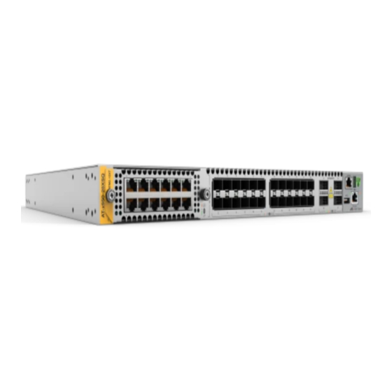
x950-28XSQ Switch
x950-28XTQm Switch
x950-52XSQ Switch
XEM2-8XSTm Ethernet Line Card
XEM2-12XT Ethernet Line Card
XEM2-12XTm Ethernet Line Card
XEM2-12XS Ethernet Line Card
XEM2-12XS v2 Ethernet Line Card
XEM2-4QS Ethernet Line Card
XEM2-1CQ Ethernet Line Card
PWR600 AC Power Supply
PWR600 DC Power Supply
FAN05 Fan Module
Installation Guide for Virtual Chassis
Stacking
613-002643 Rev. E
Advertisement
Table of Contents

Related Manuals for Allied Telesis x950 Series


Summary of Contents for Allied Telesis x950 Series
- Page 1 Series Switches Advanced Layer 3+ AlliedWare Plus™ v5.5.0-1 x950-28XSQ Switch x950-28XTQm Switch x950-52XSQ Switch XEM2-8XSTm Ethernet Line Card XEM2-12XT Ethernet Line Card XEM2-12XTm Ethernet Line Card XEM2-12XS Ethernet Line Card XEM2-12XS v2 Ethernet Line Card XEM2-4QS Ethernet Line Card...
- Page 2 Allied Telesis, Inc. has been advised of, known, or should have known, the...
- Page 3 Electrical Safety and Emissions Standards This product meets the following standards. U.S. Federal Communications Commission Radiated Energy Note: This equipment has been tested and found to comply with the limits for a Class A digital device pursuant to Part 15 of FCC Rules.
- Page 4 Translated Safety Statements Important: Safety statements that have the symbol are translated into multiple languages in the Translated Safety Statements document at www.alliedtelesis.com/library. Remarque: Les consignes de sécurité portant le symbole sont traduites dans plusieurs langues dans le document Translated Safety Statements, disponible à l'adresse www.alliedtelesis.com/ library.
-
Page 5: Table Of Contents
Contents Preface....................................15 Document Conventions ..............................16 Contacting Allied Telesis ..............................17 Chapter 1: Overview ................................ 19 x950 Switches ................................20 Features ..................................22 Hardware Features ...............................22 XEM2 Ethernet Line Cards ...........................22 Management Software and Interfaces ........................23 Management Methods ............................23 Management Panel ...............................23 Power Supplies ..............................24 Ports for 1/2.5/5/10Gbps SFP/SFP+ Transceivers.......................25... - Page 6 Contents Transceivers Port LEDs............................57 XEM2-12XT Line Card ..............................59 Twisted Pair Ports ..............................59 LEDs..................................60 XEM2-12XTm Line Card.............................. 61 Twisted Pair Ports ..............................61 LEDs..................................62 XEM2-12XS and XEM2-12XS v2 Line Cards ......................63 Transceiver Ports ..............................63 Card Versions...............................
- Page 7 x950-28XSQ Switch and VCStack Installation Guide Installation Guidelines ..............................153 Tools and Material...............................153 Installing the Plywood Base ............................155 Installing the Switch on the Plywood Base .........................156 Installing the Switch on a Concrete Wall ........................159 Chapter 9: Installing the Switch in the RKMT-SL01 Sliding Rack ................163 Introduction.................................164 Rack Mount Kit Components............................165 Adjustable Outer Rails ............................165...
- Page 8 Contents Replacing FAN05 Modules ............................251 Removing Fan Modules ............................. 251 Installing Fan Modules ............................253 Chapter 15: Troubleshooting ............................257 Appendix A: Technical Specifications ......................... 263 Physical Specifications .............................. 264 Environmental Specifications............................. 267 Power Specifications ..............................268 Certifications ................................277 RJ-45 Twisted Pair Port Pinouts..........................
- Page 9 Figures Figure 1: Front Panels of the x950 Switches ........................20 Figure 2: Rear Panel of the x950 Switches .......................... 21 Figure 3: Link and Activity LEDs for Ports for 1/2.5/5/10Gbps SFP/SFP+ Transceivers............26 Figure 4: Link and Activity LEDs for Ports 1 to 24 on the x950-28XTQm Switch ..............28 Figure 5: QSFP-4SFP10G-3CU or QSFP-4SFP10G-5CU Copper Breakout Cable ............30 Figure 6: ET3-MPO08-4LC-5 or ET3-MPO08-4LC-10 Fiber Optic Breakout Cable .............
- Page 10 Figures Figure 50: Accessory Kit ..............................109 Figure 51: Removing the Power Cord and Documents from the PWR600 AC Power Supply..........111 Figure 52: Removing the Partition from the PWR600 AC Power Supply Shipping Box .............112 Figure 53: Removing the Power Supply from the Shipping Box ..................113 Figure 54: Removing the Power Supply from the Shipping End-caps and Protective Bag..........113 Figure 55: Removing the Blank Power Supply Panel from Slot PSU B ................117 Figure 56: Sliding the PWR600 AC Power Supply into the Switch ..................118...
- Page 11 x950 Installation Guide for Virtual Chassis Stacking Figure 110: Example of Attaching the Extension Brackets to the Inner Rails..............180 Figure 111: Testing the Inner Rails with the Extension Brackets ..................181 Figure 112: Verifying the Length of the Extension Bracket....................181 Figure 113: Inner Rail Screw Holes for the x950-28XSQ and x950-28XTQm Switches ............
- Page 12 Figures...
- Page 13 Tables Table 1: Link and Activity Status LEDs for Ports for 1/2.5/5/10Gbps SFP/SFP+ Transceivers ...........26 Table 2: Twisted Pair Ports 1 to 24 on the x950-28XTQm Switch ..................27 Table 3: Link and Activity LEDs for Ports 1 to 24 on the x950-28XTQm Switch ..............28 Table 4: Ports for QSFP ..............................29 Table 5: Link and Activity Status LEDs for 40Gbps QSFP+ or 100Gbps QSFP28 Transceivers ........31 Table 6: Link and Activity Status LEDs for 10Gbps Breakout Cables .................32...
- Page 14 Tables Table 50: Maximum Power Supply Efficiency (Based on 100V Input Voltage) ..............273 Table 51: Heat Dissipations for the x950-28XSQ Switch ....................273 Table 52: Heat Dissipations for the x950-28XTQm Switch ....................275 Table 53: Heat Dissipations for the x950-52XSQ Switch ....................276 Table 54: Product Certifications ............................277 Table 55: Pin Signals on RJ-45 Twisted Pair Ports at 100Mbps ..................278 Table 56: Pin Signals on Twisted Pair Ports at 1/2.5/5/10Gbps ..................279...
-
Page 15: Preface
Preface This guide contains the installation instructions for the x950 Series of advanced Layer 3+ Ethernet switches. The instructions explain how to build a virtual stack of up to four units with the Virtual Chassis Stacking (VCStack) feature. For instructions on how to install the switches as stand- alone devices, refer to the x950 Series Installation Guide for Stand-alone Switches. -
Page 16: Document Conventions
Preface Document Conventions This document uses the following conventions: Note Notes provide additional information. Caution Cautions inform you that performing or omitting a specific action may result in equipment damage or loss of data. Warning Warnings inform you that performing or omitting a specific action may result in bodily injury. -
Page 17: Contacting Allied Telesis
Series Installation Guide for VCStack Contacting Allied Telesis For assistance with this product, you may contact Allied Telesis technical support by going to the Support & Services section of the Allied Telesis web site at www.alliedtelesis.com/support. The page has links to the following services: 24/7 Online Support —... - Page 18 Preface...
- Page 19 Chapter 1 Overview The chapter contains the following sections: “x950 Switches” on page 20 “Features” on page 22 “Ports for 1/2.5/5/10Gbps SFP/SFP+ Transceivers” on page 25 “Ports 1 to 24 on the x950-28XTQm Switch” on page 27 ...
-
Page 20: Chapter 1: Overview
Chapter 1: Overview x950 Switches The front panels of the switches are shown in Figure 1. Management Panel x950-28XSQ Switch Ports 1 to 24: Ports 25, 29, 33, 37: XEM2 Line Card 1/2.5/5/10 SFP/SFP+ 40Gbps or 100Gbps Expansion Slot Transceivers Transceivers, or 10Gbps Breakout Cables Management Panel... -
Page 21: Figure 2: Rear Panel Of The X950 Switches
Series Installation Guide for VCStack The rear panel is shown in Figure 2 on page 21. Two Slots for PWR600 Two FAN05 Cooling Fan Power Supply Modules Modules Figure 2. Rear Panel of the x950 Switches... -
Page 22: Features
Chapter 1: Overview Features The main hardware features of the x950 Switches are listed here. Hardware The switches have the following hardware features: Features 1RU height 24 ports on the x950-28XSQ Switch for 1Gbps SFP or 10Gbps SFP+ transceivers. Refer to “Ports for 1/2.5/5/10Gbps SFP/SFP+ Transceivers”... -
Page 23: Management Software And Interfaces
Refer to “XEM2-1CQ Line Card” on page 68. Line cards are ordered separately. Refer to the product data sheet on the Allied Telesis web site for a list of approved transceivers. Management Here are the management software and interfaces: Software and AlliedWare Plus management software. -
Page 24: Power Supplies
Chapter 1: Overview Power Supplies The switch has slots for two power supplies on the back panel. The switch can be powered by a single power supply. Adding a second power supply provides power redundancy. Power supplies are ordered separately. Refer to “PWR600 AC Power Supply”... -
Page 25: Ports For 1/2.5/5/10Gbps Sfp/Sfp+ Transceivers
They support full-duplex mode only. You can set the port speeds with Auto-Negotiation or manually. The default is Auto-Negotiation. Transceivers must be purchased separately. For a list of supported transceivers, refer to the product data sheet on the Allied Telesis web site. -
Page 26: Leds
Chapter 1: Overview LEDs The LEDs are located between the ports. Each port has one LED. Refer to Figure 3. Bottom Transceiver Slot LED Top Transceiver Slot LED Figure 3. Link and Activity LEDs for Ports for 1/2.5/5/10Gbps SFP/SFP+ Transceivers The LEDs displays link and activity status. -
Page 27: Ports 1 To 24 On The X950-28Xtqm Switch
Series Installation Guide for VCStack Ports 1 to 24 on the x950-28XTQm Switch The specifications for twisted pair ports 1 to 24 on the x950-28XTQm Switch are listed in Table 2. Table 2. Twisted Pair Ports 1 to 24 on the x950-28XTQm Switch... -
Page 28: Leds
Chapter 1: Overview LEDs This section explains the LEDs for the 100Mbps and 1/2.5/5/10Gbps twisted pair ports on the x950-28XTQm Switch. Each port has one LED that displays link and activity information. The LEDs are shown in Figure 4. Top Port LED Bottom Port LED Figure 4. -
Page 29: Ports For 40Gbps Qsfp+ Or 100Gbps Qsfp28 Transceiver, Or Breakout Cables
Series Installation Guide for VCStack Ports for 40Gbps QSFP+ or 100Gbps QSFP28 Transceiver, or Breakout Cables The x950 series switch has four ports that support the transceivers and cables listed in Table 4. Table 4. Ports for QSFP 40Gbps... -
Page 30: Leds
Chapter 1: Overview Figure 5. QSFP-4SFP10G-3CU or QSFP-4SFP10G-5CU Copper Breakout Cable The fiber optic breakout cables are ET3-MPO08-4LC-5 and ET3-MPO08-4LC-10, in lengths of 5 and 10 meters, respectively, with duplex LC connectors. Refer to Figure 6. Figure 6. ET3-MPO08-4LC-5 or ET3-MPO08-4LC-10 Fiber Optic Breakout Cable LEDs The ports for the QSFP28 and QSFP+ transceivers have one link and... -
Page 31: Figure 8: Leds For Ports 49, 53, 57, 61 On X950-52Xsq Switch
Series Installation Guide for VCStack Ports 49, 53, 57, and 61 on the x950-52XSQ switch have one link and activity status LED each. Refer to Figure 8. Transceiver port LED Figure 8. LEDs for Ports 49, 53, 57, 61 on x950-52XSQ Switch The states of the LEDs for 40Gbps QSFP+ or 100Gbps QSFP28 transceivers are defined in Table 5. -
Page 32: Port Numbering For The X950-28Xsq And X950-28Xtqm Switches
Chapter 1: Overview The LED states for breakout cables are described in Table 6. Table 6. Link and Activity Status LEDs for 10Gbps Breakout Cables State Description Solid Amber At least one of the four ports on the breakout cable has established a 10Gbps link to a network device. -
Page 33: Port Numbering For The X950-52Xsq Switch
Series Installation Guide for VCStack Table 7. Port Numbering for Ports 25 to 37 (Continued) With Fiber Optic With Breakout Port Transceiver or Cable Direct Attach Cable portn.0.37 portn.0.37 portn.0.38 portn.0.39 portn.0.40 The “n” variable is the switch’s ID number, displayed on the switch ID LED on the front panel. -
Page 34: Management Panel
Chapter 1: Overview Management Panel The components on the management panel for x950-28XSQ and x950-28XTQm switches are identified in Figure 9. CONSOLE Switch ID LED RS-232 Serial Port eco-friendly Button NET MGMT Port USB Slot Figure 9. Management Panel for the x950-28XSQ and x950-28XTQm Switches The components on the management panel for and x950-52XSQ switch are identified in Figure 10. -
Page 35: Usb Port
Series Installation Guide for VCStack USB Port You can use the USB port with a flash drive for the following functions: Provide a centralized network backup location for Autonomous Management Framework. Store backup copies of configuration files. ... -
Page 36: Console (Rs-232) Port
Chapter 1: Overview Table 9. NET MGMT Port LED State Description Solid Green The port has established a 1000 Mbps link with a network device. Flashing Green The port is transmitting or receiving data at 1000 Mbps. Solid Amber The port has established a 10 or 100 Mbps link. -
Page 37: Figure 11: Switch Id Led With The Eco-Friendly Mode Disabled
Series Installation Guide for VCStack The switch is booting up. The switch has encountered a fault condition. The VCStack feature is disabled. The switch is operating as a stand-alone unit, with the ID number 1. The switch is a member of a VCStack and has an ID number in the range of 1 to 8. -
Page 38: Eco-Friendly Button
Chapter 1: Overview eco-friendly You use the eco-friendly button on the management panel to turn the LEDs on or off. You might turn off the LEDs when you are not using them Button to monitor the control and Ethernet line cards, to conserve electricity. When the LEDs are off, the overall power consumption of the chassis is reduced by approximately 2 watts. -
Page 39: Optional Direct Attach Cables
Series Installation Guide for VCStack Optional Direct Attach Cables The optional direct attach cables listed in Table 10 offer an economical way to add 10Gbps, 40Gbps, or 100Gbps connections over short distances for switch ports or ports on XEM2 Line Cards. -
Page 40: Pwr600 Ac And Dc Power Supplies
Chapter 1: Overview PWR600 AC and DC Power Supplies The x950 series switch supports the PWR600 AC and PWR600 DC power supply units. Here are power supply guidelines: You can install either one or two power supplies in the switch. -
Page 41: Pwr600 Ac Power Supply
Series Installation Guide for VCStack PWR600 AC The PWR600 AC module is an AC power supply for the switch. The model name can be found on a label on the release tab on the front panel. Refer Power Supply to Figure 13. -
Page 42: Leds
Chapter 1: Overview LEDs The two LEDs on the front panel of the power supply are described in Table 11. Table 11. LEDs on the PWR600 AC Power Supply Green LED Amber LED Description Solid green The power supply is operating normally. -
Page 43: Pwr600 Dc Power Supply
Series Installation Guide for VCStack PWR600 DC The PWR600 DC module is a DC power supply for the switch. Refer to Figure 14. Power Supply Figure 14. PWR600 DC Power Supply LEDs The PWR600 DC power supply has the two LEDs on the front panel as shown in Figure 14. - Page 44 Chapter 1: Overview Table 12. LEDs on the PWR600 DC Power Supply Green LED Amber LED Description Solid green Blinking amber The power supply is experiencing a warning condition, but is still operating. Here are possible causes: - The power supply is overheating. - The speed of it’s fan is too low.
-
Page 45: Fan05 Cooling Fan
Series Installation Guide for VCStack FAN05 Cooling Fan The cooling unit for the chassis is the FAN05 Fan module. Refer to Figure 16. Figure 16. FAN05 Fan Module Here are the fan module guidelines: The switch comes with two pre-installed fan modules in FAN A and ... -
Page 46: Designating Ports In The Command Line Interface
Chapter 1: Overview Designating Ports in the Command Line Interface The individual ports on the switch are identified with the PORT parameter in the command line interface of the AlliedWare Plus management software. The format of the parameter is shown in Figure 17. port n.n.n Switch ID Number Slot Number... -
Page 47: Examples Of Port Numbering
Series Installation Guide for VCStack Examples of Port You must include the PORT parameter when identifying individual ports, and omit it from the last port when specifying ranges. Numbering Figure 18 identifies the slot numbers for base ports and line card ports. - Page 48 Chapter 1: Overview PORT Parameter on an XEM2 Line Card Note The x950-52XSQ switch has base ports only. This example enters the port Interface mode for ports 2 and 5 in an XEM2 line card in a switch with ID 1: awplus(config)# interface port1.1.2,port1.1.5 This example enters the port Interface mode for base port 6 as well as port 5 on an XEM2 line card in a switch with ID 2:...
-
Page 49: Software And Hardware Releases
Series Installation Guide for VCStack Software and Hardware Releases The software and hardware releases for the AlliedWare Plus operating software and x950 Switches are listed in Table 14. Table 14. Software and Hardware Releases Software Version Hardware / VCStack v5.4.8-2... - Page 50 Chapter 1: Overview...
-
Page 51: Chapter 2: Xem2 Ethernet Line Cards
Chapter 2 XEM2 Ethernet Line Cards The chapter contains the following sections: “Overview” on page 52 “XEM2-8XSTm Line Card” on page 55 “XEM2-12XT Line Card” on page 59 “XEM2-12XTm Line Card” on page 61 “XEM2-12XS and XEM2-12XS v2 Line Cards” on page 63 ... -
Page 52: Overview
Chapter 2: XEM2 Ethernet Line Cards Overview The x950-28XSQ and x950-28XTQm switches have one expansion slot on the front panel for an optional XEM2 Ethernet line card. See Figure 19. Note The x950-52XSQ switch does not support the XEM2 line cards. XEM2-8XSTm XEM2-12XT XEM2-12XTm... -
Page 53: Table 15: Xem2 Ethernet Line Cards
Series Installation Guide for VCStack The XEM2 Ethernet line cards are described in Table 15. Table 15. XEM2 Ethernet Line Cards Line Card Description XEM2-8XSTm Four twisted pair ports (1-4) with RJ-45 connectors that support the following speeds: - 100Mbps - 1/2.5/5/10Gbps... - Page 54 Chapter 2: XEM2 Ethernet Line Cards Table 15. XEM2 Ethernet Line Cards (Continued) Line Card Description XEM2-12XS and XEM2- 12 ports that support the following types of 12XS v2 transceivers: - 1/2.5/5/10Gbps SP10TM transceivers with RJ-45 connectors - 1Gbps SFP - 10Gbps SFP+ - 10Gbps one meter SP10TW1, three meter SP10TW3, and seven meter...
-
Page 55: Xem2-8Xstm Line Card
Series Installation Guide for VCStack XEM2-8XSTm Line Card The XEM2-8XSTm Line Card is shown in Figure 20. Figure 20. XEM2-8XSTm Line Card Twisted Pair The XEM2-8XSTm Card has four twisted pair ports and four SFP ports. The specifications for the twisted pair ports are listed in Table 16. -
Page 56: Twisted Pair Port Leds
Chapter 2: XEM2 Ethernet Line Cards Table 16. Twisted Pair Ports on the XEM2-8XSTm Line Card (Continued) Specification Description Cabling Minimum cable requirements are: - 100Mbps - Standard TIA/EIA 568-B- compliant Category 3 unshielded cabling. - 1/2.5/5Gbps - Standard TIA/EIA 568-A- compliant Category 5 or TIA/EIA 568-B- compliant Enhanced Category 5 (Cat 5e) unshielded cabling. -
Page 57: Transceivers Ports
Series Installation Guide for VCStack Transceivers The XEM2-8XSTm Card also has four transceiver ports that support the following types of 1Gbps SFP or 10Gbps SFP+ transceivers: Ports 1Gbps SX or LX SFP fiber optic transceivers 10Gbps SR or LR SFP+ fiber optic transceivers ... - Page 58 Chapter 2: XEM2 Ethernet Line Cards Table 18. Link and Activity LEDs for the SFP Ports on the XEM2-8XSTm Line Card (Continued) State Description Possible causes of this state are listed here: - The transceiver has not established a link with another network device. - The LEDs are turned off.
-
Page 59: Xem2-12Xt Line Card
Series Installation Guide for VCStack XEM2-12XT Line Card The XEM2-12XT Line Card is shown in Figure 21. Figure 21. XEM2-12XT Line Card Twisted Pair The card has 12 twisted pair ports with standard 8-pin RJ-45 ports. The specifications of the ports are listed in Table 19. -
Page 60: Leds
Chapter 2: XEM2 Ethernet Line Cards Table 19. Twisted Pair Ports on the XEM2-12XT Line Card (Continued) Specification Description Cabling The minimum cable requirements are: - 100Mbps - Standard TIA/EIA 568-B- compliant Category 3 unshielded cabling. - 1Gbps - Standard TIA/EIA 568-A- compliant Category 5 or TIA/EIA 568-B- compliant Enhanced Category 5 (Cat 5e) unshielded cabling. -
Page 61: Xem2-12Xtm Line Card
Series Installation Guide for VCStack XEM2-12XTm Line Card The XEM2-12XTm Card is shown in Figure 22. Figure 22. XEM2-12XTm Line Card Twisted Pair The XEM2-12XTm Card has 12 twisted pair ports with standard 8-pin RJ- 45 ports. The specifications of the ports are listed in Table 21. -
Page 62: Leds
Chapter 2: XEM2 Ethernet Line Cards Table 21. Twisted Pair Ports on the XEM2-12XTm Line Card (Continued) Specification Description Cabling Cable minimum requirements are: - 100Mbps - Standard TIA/EIA 568-B- compliant Category 3 unshielded cabling. - 1/2.5/5Gbps - Standard TIA/EIA 568-A- compliant Category 5 or TIA/EIA 568-B- compliant Enhanced Category 5 (Cat 5e) unshielded cabling. -
Page 63: Xem2-12Xs And Xem2-12Xs V2 Line Cards
Series Installation Guide for VCStack XEM2-12XS and XEM2-12XS v2 Line Cards The XEM2-12XS Line Card is shown in Figure 23. Figure 23. XEM2-12XS Line Card Transceiver Ports The card has twelve ports that support the following types of 1Gbps SFP, 10Gbps SFP+, and 1/2.5/5/10Gbps transceivers with RJ-45 connectors:... -
Page 64: Card Versions
Chapter 2: XEM2 Ethernet Line Cards Guidelines about the ports are listed here: They do not support 100Mbps transceivers. They support full-duplex mode only. You can set the port speeds with Auto-Negotiation or manually. The default is Auto-Negotiation. SFP or SFP+ transceivers are purchased separately. - Page 65 Series Installation Guide for VCStack Table 23. Port Link and Activity LEDs on the XEM2-12XS Line Card State Description Solid Amber The transceiver has established a 1GBase link to a network device. Flashing Amber The transceiver is transmitting or receiving data at 1GBase.
-
Page 66: Xem2-4Qs Line Card
Chapter 2: XEM2 Ethernet Line Cards XEM2-4QS Line Card The XEM2-4QS Line Card is shown in Figure 25. Figure 25. XEM2-4QS Line Card Transceiver Ports The card supports the following types of 40Gbps QSFP+ transceivers in its four ports: QSFPSR4 transceiver - Maximum operating distance of 150 ... -
Page 67: Leds
Series Installation Guide for VCStack LEDs The LED states for transceivers or direct attach cables in ports on the XEM2-4QS Line Card are described in Table 24. Table 24. Port Link and Activity Status LEDs on the XEM2-4QS Line Card... -
Page 68: Xem2-1Cq Line Card
Chapter 2: XEM2 Ethernet Line Cards XEM2-1CQ Line Card The XEM2-1CQ Line Card is shown in Figure 26. Figure 26. XEM2-1CQ Line Card Transceiver Port The one port on the card supports the following 100Gbps QSFP28 transceivers: QSFP28SR4 transceiver - Maximum operating distance of 70m ... - Page 69 Series Installation Guide for VCStack Table 26. Port Link and Activity Status LED on the XEM2-1CQ Line Card State Description Flashing Green The transceiver is transmitting or receiving data. Possible causes of this state are listed here: - The transceiver slot is empty.
- Page 70 Chapter 2: XEM2 Ethernet Line Cards...
-
Page 71: Chapter 3: Virtual Chassis Stacking
“Planning a Stack” on page 92 “Stacking Worksheet” on page 93 Note For more information on VCStack, refer to the Stacking Introduction and Stacking Commands chapters in the Software Reference for x950 Series Switches, AlliedWare Plus Operating System from www.alliedtelesis.com/support. -
Page 72: Overview
Chapter 3: Virtual Chassis Stacking Overview The Virtual Chassis Stacking (VCStack) feature enables you link together up to four x950 Switches into a virtual stack so that they function as a single networking unit. The feature provides the following benefits: Simplifies management - You can manage the devices as a single ... -
Page 73: Stacking Guidelines
Series Installation Guide for VCStack Stacking Guidelines Here are general stacking guidelines: AlliedWare Plus v5.4.8-2 or later supports stacks of two switches. AlliedWare Plus v5.4.9 or later supports stacks up to four switches. AlliedWare Plus v5.4.9-2.3, v5.5.0 or later supports stacks up to ... -
Page 74: Stack Trunks
Allied Telesis. Transceivers or cables from other network equipment providers might not perform properly as trunks. For a list of supported transceivers, refer to the Allied Telesis web site. A stack of x950 Switches cannot include other stacking products, ... - Page 75 Series Installation Guide for VCStack The trunk can have up to eight ports per switch. The more ports in the trunk, the greater its bandwidth and resiliency. You can use any of the ports for the trunk. ...
-
Page 76: Figure 27: Example Stacks Of X950-28Xsq Switches With Trunks Of 10Gbps Ports
Chapter 3: Virtual Chassis Stacking When possible, try cabling the same trunk ports together. For example, if you select ports 6 to 9 as trunk ports, cable port 6 on one switch to port 6 on the next, port 7 to port 7, and so on. Again, this is not mandatory, but it can make managing or troubleshooting the stack easier. -
Page 77: Figure 28: Example Stacks Of X950-28Xtqm Switches With Trunks Of 10Gbps Ports
Series Installation Guide for VCStack Figure 28 has examples of stacks with 10Gbps trunks for two, three, or four x950-28XTQm Switches. The examples use ports 1 to 4 for the trunks. As a reminder, a trunk of ports 1 to 24 can have up to eight ports per switch and you can use any of the ports. -
Page 78: Figure 29: Example Stack Trunks Of 10Gbps Links On X950-28Xsq And X950-52Xsq Switches
Chapter 3: Virtual Chassis Stacking Figure 29 has examples of stacks with 10Gbps trunks with combinations of two, three, or four x950-28XSQ and x950-52XSQ switches. The examples use ports 1 to 4 for the trunks. As a reminder, a trunk of ports 1 to 24 on the x950-28XSQ switch and ports 1 to 48 on the x950-52XSQ switch can have up to eight ports per switch and you can use any of the ports. -
Page 79: Ports 25 To 37 And Ports 49 To 61 With 40Gbps Transceivers
Series Installation Guide for VCStack Ports 25 to 37 and You can also use ports 25 to 37 on the x950-28XSQ or x950-28XTQm switch and ports 49 to 61 on the x950-52XSQ switch for stack trunks. Ports 49 to 61 These ports support both 40Gbps and 100Gbps transceivers. -
Page 80: Ports 25 To 37 And Ports 49 To 61 With 100Gbps Transceivers
Chapter 3: Virtual Chassis Stacking To build stacks of three or four switches, Allied Telesis recommends using all four ports. Examples are shown in Figure 31. Please note how the top and bottom switches are connected to form a loop in the trunk. -
Page 81: Figure 32: Stack Trunk Examples With 100Gbps Links
Series Installation Guide for VCStack Because the trunk cannot have more than two 100Gbps ports per switch, stacks of three or four switches can have only one link between switches. Stacks can have any combination of x950-28XSQ, x950-28XTQm, ... -
Page 82: Xem2 Line Cards
12XS v2 Line Cards have to use 10Gbps SFP+ transceivers. They cannot be used as trunk ports at lower speeds. 3. Allied Telesis does not recommend using the XEM2-1CQ Line Card for a stack trunk. Figure 33 on page 83 is an example of a stack of two switches with ... -
Page 83: Figure 33: Example Trunk Using Xem2-12Xt Line Cards
Series Installation Guide for VCStack Figure 33. Example Trunk Using XEM2-12XT Line Cards Figure 34 is an example of a stack of three switches with a trunk from ports on XEM2-12XS Line Cards. Figure 34. Example Trunk Using XEM2-12XS Line Cards Figure 35 on page 84 is an example of a stack of four switches with ... -
Page 84: Unsupported Trunks
Chapter 3: Virtual Chassis Stacking Figure 35. Example Trunk Using XEM2-4QS Line Cards Unsupported The following are examples of unsupported trunks. Trunks In stacks of three or four switches, the number of links in the trunk has to be the same on all switches. The trunk in Figure 36 is unsupported because the middle switch is connected to the top and bottom switches with two links each, while the top and bottom switches are connected with only one link. -
Page 85: Figure 37: Unsupported Trunk With Mixed Cables
Series Installation Guide for VCStack Wiring Room 1 SP10TW Direct Attach Cables Fiber Optic Cables Wiring Room 2 Figure 37. Unsupported Trunk with Mixed Cables Trunks cannot have both base ports and XEM2 Line Card ports. The unsupported trunk in Figure 38 consists of base 10Gbps ports and ports on XEM2-12XS Line Cards. -
Page 86: Figure 40: Unsupported Trunk With Only One Link Between Switches
10Gbps 100Gbps Figure 41. Unsupported Trunk with Different Port Speeds Allied Telesis does not recommend using the XEM2-1CQ Line Card for a stack trunk because it has only one transceiver port and the switch has only one expansion port. Refer to Figure 42 on page 87. -
Page 87: Figure 42: Not Recommended Stack Trunk Of Xem2-1Cq Line Cards
Series Installation Guide for VCStack 100Gbps Figure 42. Not Recommended Stack Trunk of XEM2-1CQ Line Cards You cannot use a 10Gbps breakout cable for a trunk. Refer to Figure 43. Breakout Cable Figure 43. Unsupported Trunk with a 10Gbps Breakout Cable The base 10Gbps transceiver ports and XEM2-12XS Line Card ... -
Page 88: Figure 44: Unsupported Trunk With Intermediary Network Devices
Chapter 3: Virtual Chassis Stacking Wiring closet 1 Media Converters Wiring closet 2 Figure 44. Unsupported Trunk with Intermediary Network Devices... -
Page 89: Master And Member Switches
Series Installation Guide for VCStack Master and Member Switches One switch of a stack functions as a master switch. Its main functions are listed here: Coordinate and monitor stack operations. Verify that the switches are using the same version of ... -
Page 90: Switch Id Numbers
Chapter 3: Virtual Chassis Stacking Switch ID Numbers Each switch must have an ID number. The range is 1 to 4. The default is 1. The ID numbers are displayed on the ID LEDs on the front panels of the units. -
Page 91: Optional Feature Licenses
Allied Telesis. Contact your authorized reseller or distributor for a list of optional features licenses for this product. Here are the guidelines to feature licenses for a stack of x950 Series switches: The VCStack feature is part of the base features of the switch. It ... -
Page 92: Planning A Stack
Chapter 3: Virtual Chassis Stacking Planning a Stack Here are questions you need to answer before building or configuring a stack: How many switches will be in the stack? AlliedWare Plus v5.4.8-2 supports stacks of two switches. AlliedWare Plus v5.4.9 or later supports stacks up to four switches. -
Page 93: Stacking Worksheet
Series Installation Guide for VCStack Stacking Worksheet The worksheet in Table 28 is here to assist you in configuring and maintaining a stack. Table 28. Stacking Worksheet Firmware Transceivers in Switch/ Prior- Trunk XEM2 Switch Version Slots 25 to 37 or... -
Page 94: Table 29: Stacking Worksheet Columns
ID LEDs on the front panels and you use the numbers to configure the individual ports. Allied Telesis recommends assigning the ID 1, the default value, to the master switch. You should decide on the ID assignments of the switches before beginning the configuration procedures. - Page 95 Series Installation Guide for VCStack Table 29. Stacking Worksheet Columns (Continued) Column Description Firmware Version Use this column to record the version numbers of Number the AlliedWare Plus management software on the switches. The switches might not be able to form the stack if they have different versions.
-
Page 96: Table 30: Example Of A Completed Stack Worksheet
Chapter 3: Virtual Chassis Stacking Table 30 is an example of a completed worksheet. Table 30. Example of a Completed Stack Worksheet Firmware Transceivers in Switch/ Prior- Trunk XEM2 Switch Switch Version Slots Location Ports Card Number 25 to 37 Master x950- v5.4.9-0... -
Page 97: Chapter 4: Beginning The Installation
Chapter 4 Beginning the Installation The chapter contains the following sections: “Reviewing Safety Precautions” on page 98 “Installation Options” on page 103 “Choosing a Site for the Chassis” on page 104 “Unpacking the Switch” on page 105 ... -
Page 98: Reviewing Safety Precautions
Chapter 4: Beginning the Installation Reviewing Safety Precautions Please review the following safety precautions before beginning the installation procedure. Note Safety statements that have the symbol are translated into multiple languages in the Translated Safety Statements document at www.alliedtelesis.com/support. Warning Class 1 Laser product. - Page 99 Series Installation Guide for VCStack Warning Power cord is used as a disconnection device. To de-energize equipment, disconnect the power cord. E3 Warning Class I Equipment. This equipment must be earthed. The power plug must be connected to a properly wired earth ground socket outlet.
- Page 100 Mounting of the equipment in the rack should be such that a hazardous condition is not created due to uneven mechanical loading. E25 Warning The chassis may be heavy and awkward to lift. Allied Telesis recommends that you get assistance when mounting the chassis in an equipment rack. E28...
- Page 101 Series Installation Guide for VCStack Note Use dedicated power circuits or power conditioners to supply reliable electrical power to the device. E27 Warning This unit might have more than one power cord. To reduce the risk of electric shock, disconnect all power cords before servicing the unit.
- Page 102 Chapter 4: Beginning the Installation Warning This equipment shall be installed in a Restricted Access location. Caution The unit does not contain serviceable components. Please return damaged units for servicing. E42 Warning The temperature of an operational SFP or SFP+ transceiver may exceed 70°...
-
Page 103: Installation Options
Series Installation Guide for VCStack Installation Options Figure 45 illustrates the four installation options. Tabletop 19-inch Equipment Rack with Standard Brackets 19-inch Equipment Rack with Optional RKMT-SL01 Sliding Wall Installation with Rack Mount Kit Standard Brackets Figure 45. Installation Options... -
Page 104: Choosing A Site For The Chassis
Chapter 4: Beginning the Installation Choosing a Site for the Chassis Observe these site requirements. If you are installing the device in an equipment rack, check that the rack is safely secured so that it will not tip over. Devices should be installed in the rack starting at the bottom, with the heavier devices near the bottom of the rack. -
Page 105: Unpacking The Switch
Series Installation Guide for VCStack Unpacking the Switch To unpack the switch from its shipping box, perform the following procedure: 1. Remove the accessories and documents from the accessory partition. Refer to Figure 46. Figure 46. Removing Accessories 2. Remove the accessory partition. Refer to Figure 47 on page 106. -
Page 106: Figure 47: Removing The Shipping Partition
Chapter 4: Beginning the Installation Figure 47. Removing the Shipping Partition 3. Lift the switch from the shipping box and place it on a level, secure table. Refer to Figure 48 on page 107. Warning The switch is heavy. Ask for assistance lifting the device out of the shipping box. -
Page 107: Figure 48: Lifting The Switch From The Shipping Box
Series Installation Guide for VCStack Figure 48. Lifting the Switch from the Shipping Box 4. Remove the switch from the shipping end-caps and protective bag. Refer to Figure 49. Figure 49. Removing the Switch from the Shipping End-caps and... - Page 108 Chapter 4: Beginning the Installation 5. Visually inspect the product for damage. 6. Visually inspect the front panel for the components shown in Figure 1 on page 20. 7. Verify that there are two pre-installed fan modules in FAN A and FAN B slots on the rear panel.
-
Page 109: Verifying The Accessory Kit
Series Installation Guide for VCStack Verifying the Accessory Kit Figure 50 lists the accessory items that are included with the switch. One 2 m (6.6 ft) local management cable with RJ-45 (8P8C) and DB-9 (D-sub 9-pin) connectors. Sixteen bracket screws... - Page 110 Chapter 4: Beginning the Installation Note If any item is missing or damaged, contact your Allied Telesis sales representative for assistance. After unpacking the switch and verifying the accessory kit, go to “Unpacking the PWR600 AC Power Supply” on page 111 or “Unpacking...
-
Page 111: Unpacking The Pwr600 Ac Power Supply
Series Installation Guide for VCStack Unpacking the PWR600 AC Power Supply To unpack the PWR600 Power Supply, perform the following procedure: 1. Remove the power cord and any documents from the accessory partition. Refer to Figure 51. Figure 51. Removing the Power Cord and Documents from the PWR600 AC Power Supply 2. -
Page 112: Figure 52: Removing The Partition From The Pwr600 Ac Power Supply Shipping Box
Chapter 4: Beginning the Installation Figure 52. Removing the Partition from the PWR600 AC Power Supply Shipping Box 3. Lift the power supply from the shipping box and place it on a level, secure table. Refer to Figure 53 on page 113. Warning The power supply is heavy. -
Page 113: Figure 53: Removing The Power Supply From The Shipping Box
Series Installation Guide for VCStack Figure 53. Removing the Power Supply from the Shipping Box 4. Remove the power supply from the shipping end-caps and protective shipping bag. Refer to Figure 54. Figure 54. Removing the Power Supply from the Shipping End-caps and Protective Bag 5. -
Page 114: Unpacking The Pwr600 Dc Power Supply
Chapter 4: Beginning the Installation Unpacking the PWR600 DC Power Supply To unpack the PWR600 DC Power Supply, perform the following procedure: 1. Open the box and remove the PWR600 DC power supply. 2. Visually inspect the product for damage. 3. -
Page 115: Chapter 5: Installing Power Supplies And Optional Xem2 Line Card
Chapter 5 Installing Power Supplies and Optional XEM2 Line Card This chapter has the following procedures: “Installing PWR600 AC Power Supplies” on page 116 “Installing PWR600 DC Power Supplies” on page 120 “Connecting the Grounding Wire” on page 123 ... -
Page 116: Installing Pwr600 Ac Power Supplies
PSU A and PSU B on the left side of the rear panel. If you are installing only one power supply, you can install it in either slot. Allied Telesis recommends PSU A because that slot does not come with a blank power supply panel. -
Page 117: Figure 55: Removing The Blank Power Supply Panel From Slot Psu B
Series Installation Guide for VCStack Release Tab Figure 55. Removing the Blank Power Supply Panel from Slot PSU B... -
Page 118: Figure 56: Sliding The Pwr600 Ac Power Supply Into The Switch
Chapter 5: Installing Power Supplies and Optional XEM2 Line Card 3. Carefully align the power supply in the slot and slide it into the slot. Figure 56 shows the module aligned for the PSU A slot. Figure 56. Sliding the PWR600 AC Power Supply into the Switch... -
Page 119: Figure 57: Seating The Power Supply On The Internal Connector
Series Installation Guide for VCStack 4. When the power supply makes contact with the connector inside the switch, gently press on its faceplate to seat it on the connector. Refer to Figure 57. Figure 57. Seating the Power Supply on the Internal Connector 5. -
Page 120: Installing Pwr600 Dc Power Supplies
PSU A and PSU B on the left side of the rear panel. If you are installing only one power supply, you can install it in either slot. Allied Telesis recommends PSU A because that slot does not come with a blank power supply panel. -
Page 121: Figure 58: Sliding The Pwr600 Dc Power Supply Into The Chassis
Series Installation Guide for VCStack Figure 58. Sliding the PWR600 DC Power Supply into the Chassis 4. When the power supply makes contact with the connector inside the switch, gently press on its faceplate to seat it on the connector. - Page 122 Chapter 5: Installing Power Supplies and Optional XEM2 Line Card Chapter 7, “Installing the Switch in an Equipment Rack” on page Chapter 8, “Installing the Switch on a Wall” on page 147 Chapter 9, “Installing the Switch in the RKMT-SL01 Sliding Rack” ...
-
Page 123: Connecting The Grounding Wire
Series Installation Guide for VCStack Connecting the Grounding Wire Here are the guidelines for the grounding wire: The wire should be minimum #16 AWG solid wire. The wire length should be as short as possible. Continuity from the grounding screw to the earth ground must be ... -
Page 124: Figure 60: Loosening The Screw For The Panel
Chapter 5: Installing Power Supplies and Optional XEM2 Line Card Figure 60. Loosening the Screw for the Panel 3. Press the panel to the right to expose the connectors as shown in Figure 61 on page 124. Figure 61. Accessing the Connectors... -
Page 125: Figure 62: Loosening The Ground Screw
Series Installation Guide for VCStack 4. Loosen the ground screw with a Phillips-head screwdriver. Refer to Figure 62. Figure 62. Loosening the Ground Screw 5. Wind the grounding wire clockwise around the base of the grounding screw. Refer to Figure 63 on page 125. -
Page 126: Connecting The Dc Power Wires
Chapter 5: Installing Power Supplies and Optional XEM2 Line Card Connecting the DC Power Wires Here are the materials and tools for connecting the DC power cables: 18 AWG stranded wires. Do not use wire heavier than 16 AWG. solid wire. -
Page 127: Figure 66. Loosening The Screw For The Negative
Series Installation Guide for VCStack Note Allied Telesis recommends tinning the wires with solder for added protection against loose strands. This guide does not provide instructions on how to tin wires. 3. Loosen the middle screw for the negative (-) with a Phillips-head screwdriver. -
Page 128: Figure 68: Loosening The Screw For The Negative (+)
Chapter 5: Installing Power Supplies and Optional XEM2 Line Card Figure 68. Loosening the Screw for the Negative (+) 6. Wind the power wire and tighten the screw.Refer to Figure 69. Figure 69. Tightening the Screw for the Negative (+) 7. -
Page 129: Figure 70: Placing The Cover Panel
Series Installation Guide for VCStack 8. Place the cover panel back to cover the connectors. Refer to Figure Figure 70. Placing the Cover Panel 9. Tighten the screw for the cover panel. Refer to Figure 72. Figure 71. Tightening the Screw for the Cover Panel... -
Page 130: Installing An Optional Xem2 Ethernet Line Card
Chapter 5: Installing Power Supplies and Optional XEM2 Line Card Installing an Optional XEM2 Ethernet Line Card This section contains the procedure for installing an optional XEM2 Ethernet line card in the expansion slot in the front panel of the x950-28XSQ and x950-28XTQm switches. -
Page 131: Figure 73: Removing The Ethernet Line Card From The Anti-Static Bag
Series Installation Guide for VCStack Figure 73. Removing the Ethernet Line Card from the Anti-static Bag 3. Position the line card with the notch on the faceplate in the bottom left corner, as shown in Figure 74, and carefully slide it into the slot. -
Page 132: Figure 75: Seating The Ethernet Line Card In The Expansion Slot
Chapter 5: Installing Power Supplies and Optional XEM2 Line Card 4. When the line card makes contact with the internal connector in the switch. gently press on the sides of its faceplate to seat it on the connector. Refer to Figure 75. Figure 75. -
Page 133: Figure 76: Tightening The Two Captive Screws On The Ethernet Line Card
Series Installation Guide for VCStack Figure 76. Tightening the Two Captive Screws on the Ethernet Line Card 7. After installing the power supplies and optional XEM2 Line Card, go to one of the following chapters: Chapter 6, “Installing the Switch on a Table” on page 135 ... - Page 134 Chapter 5: Installing Power Supplies and Optional XEM2 Line Card...
-
Page 135: Chapter 6: Installing The Switch On A Table
Chapter 6 Installing the Switch on a Table This chapter contains the instructions for installing the switch on a table or desktop. Warning Switches should not be stacked on a table or desktop. They could present a physical safety hazard if you need to move or replace switches. -
Page 136: Figure 78: Holes For Bumper Feet
Chapter 6: Installing the Switch on a Table Rear of Chassis Front of Chassis Figure 78. Holes for Bumper Feet Note The following procedure assumes that you have already reviewed the information and performed the procedures in Chapter 4, “Beginning the Installation” on page 97. To install the switch on a table, perform the following procedure: 1. -
Page 137: Figure 80: Placing The Bumper Foot On A Base Corner Hole
Series Installation Guide for VCStack 3. Place the bumper foot onto one of the holes in the base of the switch. Refer to Figure 80. Figure 80. Placing the Bumper Foot on a Base Corner Hole 4. Insert the rivet to secure the bumper foot to the base. Refer to Figure 81. - Page 138 Chapter 6: Installing the Switch on a Table 7. Do one of the following: To install power supplies, go to “Installing PWR600 AC Power Supplies” on page 116 or “Installing PWR600 DC Power Supplies” on page 120. To install an optional XEM2 Ethernet Line Card, go to “Installing an ...
-
Page 139: Chapter 7: Installing The Switch In An Equipment Rack
Chapter 7 Installing the Switch in an Equipment Rack This chapter contains instructions for installing the switch in a standard 19- inch equipment rack. The procedures in this chapter are listed here: “Beginning the Installation” on page 140 “Removing the Bumper Feet” on page 142 ... -
Page 140: Beginning The Installation
Chapter 7: Installing the Switch in an Equipment Rack Beginning the Installation This chapter contains the procedure for installing the switch in a standard 19-inch equipment rack, with the brackets included with the unit. Required Items The following items are required to install the switch in an equipment rack: Two equipment rack brackets (included with the switch) ... -
Page 141: Figure 83: Switch Orientations In An Equipment Rack
Series Installation Guide for VCStack Figure 83. Switch Orientations in an Equipment Rack... -
Page 142: Removing The Bumper Feet
Chapter 7: Installing the Switch in an Equipment Rack Removing the Bumper Feet The bumper feet included with the switch should not be used when installing the device in an equipment rack. If they are already installed, perform the following procedure to remove them: 1. -
Page 143: Installing The Switch
Please review the information and perform the procedures in Chapter 4, “Beginning the Installation” on page 97 before installing the switch. Caution The chassis may be heavy and awkward to lift. Allied Telesis recommends that you get assistance when mounting the chassis in an equipment rack. E28... -
Page 144: Figure 85: Attaching The Equipment Rack Brackets
Chapter 7: Installing the Switch in an Equipment Rack Figure 85. Attaching the Equipment Rack Brackets 4. Have another person hold the switch in the equipment rack while you secure it using standard equipment rack screws (not provided). Refer to Figure 86. Figure 86. - Page 145 Series Installation Guide for VCStack 5. Do one of the following: To install power supplies, go to “Installing PWR600 AC Power Supplies” on page 116. To install an optional XEM2 Ethernet Line Card, go to “Installing an ...
- Page 146 Chapter 7: Installing the Switch in an Equipment Rack...
-
Page 147: Chapter 8: Installing The Switch On A Wall
Chapter 8 Installing the Switch on a Wall The procedures in this chapter are listed here: “Switch Orientations on a Wall” on page 148 “Recommended Minimum Wall Area Dimensions” on page 149 “Plywood Base for a Wall with Wooden Studs” on page 151 ... -
Page 148: Switch Orientations On A Wall
Chapter 8: Installing the Switch on a Wall Switch Orientations on a Wall You can install the switch on a wall with the front panel on the left or right, as shown in Figure 87. Do not install it with the front panel on the top or bottom. -
Page 149: Recommended Minimum Wall Area Dimensions
Series Installation Guide for VCStack Recommended Minimum Wall Area Dimensions The recommended minimum dimensions for the reserved wall area for the switch are listed here: Width: 77.4 centimeters (31 inches) Height: 58.4 centimeters (23 inches) Figure 88 and Figure 89 on page 150 illustrate the recommended positions of the switch in the reserved area when the front panel is on the left and right, respectively. -
Page 150: Figure 89: Minimum Wall Area Dimensions With The Front Panel On The Right
Chapter 8: Installing the Switch on a Wall Figure 89. Minimum Wall Area Dimensions with the Front Panel on the Right... -
Page 151: Plywood Base For A Wall With Wooden Studs
Series Installation Guide for VCStack Plywood Base for a Wall with Wooden Studs If you are installing the switch on a wall that has wooden studs, Allied Telesis recommends using a plywood base for the device. (A plywood base is not required for a concrete wall.) Refer to Figure 90. -
Page 152: Figure 91: Steps To Installing The Switch With A Plywood Base
Chapter 8: Installing the Switch on a Wall The recommended minimum dimensions of the plywood base are listed here: Width: 58.4 centimeters (23 inches) Height: 55.9 centimeters (22 inches) Thickness: 5.1 centimeters (2 inches) The dimensions assume the wall studs are 41 centimeters (16 inches) apart. -
Page 153: Installation Guidelines
Series Installation Guide for VCStack Installation Guidelines Here are the guidelines to installing the switch on a wall: You may install the switch on a wall that has wooden studs. You may install it on a concrete wall. - Page 154 Chapter 8: Installing the Switch on a Wall Cross-head screwdriver (not provided) Stud finder for a wooden wall, capable of identifying the middle of wall studs and hot electrical wiring (not provided) Drill and 1/4” carbide drill bit for a concrete wall (not provided) ...
-
Page 155: Installing The Plywood Base
Series Installation Guide for VCStack Installing the Plywood Base A plywood base is recommended when installing the switch on a wall that has wooden studs. Refer to “Plywood Base for a Wall with Wooden Studs” on page 151. Consult a qualified building contractor for installation instructions for the plywood base. -
Page 156: Installing The Switch On The Plywood Base
This procedure assumes that the plywood base for the switch is already installed on the wall. Please review “Reviewing Safety Precautions” on page 98 and “Choosing a Site for the Chassis” on page 104 before performing this procedure. Allied Telesis recommends a minimum of three people for this procedure. Warning The device is heavy. -
Page 157: Figure 93: Attaching The Switch To The Plywood Base
Series Installation Guide for VCStack The sides of the switch have two sets of holes. One set is for installing the switch on a wall with the brackets and the other is for the RKMT- SL01 Rack Mounting Kit. For this procedure, you need to use the bracket holes, identified in Figure 82 on page 140. - Page 158 Chapter 8: Installing the Switch on a Wall 4. Do one of the following: To install the power supplies, go to “Installing PWR600 AC Power Supplies” on page 116. To install an optional XEM2 Ethernet Line Card, go to “Installing an ...
-
Page 159: Installing The Switch On A Concrete Wall
Series Installation Guide for VCStack Installing the Switch on a Concrete Wall Allied Telesis recommends a minimum of three people for this procedure. To install the switch on a concrete wall, perform the following procedure: Warning The device is heavy. Always ask for assistance before moving or lifting it to avoid injuring yourself or damaging the equipment. -
Page 160: Figure 94: Marking The Locations Of The Bracket Holes On A Concrete Wall
3. Please review the following guidelines: Prior to drilling, set the drill to hammer and rotation mode. The modes break up the concrete and clean out the hole. Allied Telesis recommends cleaning out the holes with a brush or compressed air. -
Page 161: Figure 95: Installing The Switch On A Concrete Wall
Series Installation Guide for VCStack 6. Insert the four anchors into the holes. 7. Have two people hold the switch at the selected wall location while you secure it to the wall with the four provided screws. Refer to Figure 95. - Page 162 Chapter 8: Installing the Switch on a Wall...
-
Page 163: Chapter 9: Installing The Switch In The Rkmt-Sl01 Sliding Rack
Chapter 9 Installing the Switch in the RKMT-SL01 Sliding Rack This appendix contains the following sections: “Introduction” on page 164 “Rack Mount Kit Components” on page 165 “Equipment Rack Requirements” on page 167 “Reviewing Safety Precautions” on page 168 ... -
Page 164: Introduction
Introduction The RKMT-SL01 Rack Mount Kit is a slide-rail type rack-mount kit for Allied Telesis switches in EIA standard 19-inch equipment racks. The kit makes installation and maintenance of network equipment easier by letting you slide switches into or out of equipment racks, including server racks with deep dimensions. -
Page 165: Rack Mount Kit Components
Series Installation Guide for VCStack Rack Mount Kit Components The kit has three main components. Adjustable Outer Two adjustable outer rails attach to the equipment rack. They are suitable for racks with depths of 600 mm (23.6 in) to 900 mm (35.4 in). Refer to Rails Figure 96. -
Page 166: Figure 98: Extension Brackets
Chapter 9: Installing the Switch in the RKMT-SL01 Sliding Rack Figure 98. Extension Brackets... -
Page 167: Equipment Rack Requirements
Series Installation Guide for VCStack Equipment Rack Requirements The Rack Mount Kit is designed for equipment racks that meet the following requirements: The depth can be from 600 mm (23.6 in) to 900 mm (35.4 in). The width should be a minimum of 452 mm (17.8 in). -
Page 168: Reviewing Safety Precautions
available in a PDF document titled Translated Safety Statements posted on the Allied Telesis website at www.alliedtelesis.com/ support. Warning Mounting of the equipment in the rack should be such that a hazardous condition is not created due to uneven mechanical loading. - Page 169 Series Installation Guide for VCStack Caution Use the adjustment bracket screws supplied with the inner rail. Using screws other than those supplied may result in equipment damage. Warning When installing the outer and inner rails, and adjustment bracket, ensure the components are securely attached with the appropriate screws.
- Page 170 Chapter 9: Installing the Switch in the RKMT-SL01 Sliding Rack Warning Do not pull the switch out past the front rack posts. ...
-
Page 171: Installation Overview
Series Installation Guide for VCStack Installation Overview The following steps summarize the installation procedure for the RKMT- SL01 Rack Mount Kit: 1. Verify the contents of the shipping box. Refer to “Unpacking the Shipping Container” on page 172. 2. Attach the outer rails to the equipment rack. Refer to “Installing the Outer Rails on the Equipment Rack”... -
Page 172: Unpacking The Shipping Container
Chapter 9: Installing the Switch in the RKMT-SL01 Sliding Rack Unpacking the Shipping Container The contents of the shipping container are shown in Figure 99. Two inner rails - They attach to Two outer rails - They attach to the the sides of the switch. - Page 173 Series Installation Guide for VCStack Note Store the packaging material in a safe location. You should use the original shipping material if you need to return the kit to Allied Telesis. Warning When installing the outer and inner rails, and extension brackets, ensure the components are securely attached with the appropriate screws.
-
Page 174: Installing The Outer Rails On The Equipment Rack
Chapter 9: Installing the Switch in the RKMT-SL01 Sliding Rack Installing the Outer Rails on the Equipment Rack To install the outer rails to the equipment rack, perform the following procedure. 1. Locate the FRONT and REAR labels on the sides of the rails. You have to install the rails with the FRONT labels at the front of the equipment rack and the REAR Labels at the back. -
Page 175: Figure 101: Installing The Outer Rails On The Equipment Rack
Series Installation Guide for VCStack Front of Equipment Rack Figure 101. Installing the Outer Rails on the Equipment Rack... -
Page 176: Installing The Extension Brackets On The Inner Rails
Chapter 9: Installing the Switch in the RKMT-SL01 Sliding Rack Installing the Extension Brackets on the Inner Rails The kit comes with two extension brackets. Refer to Figure 102. Figure 102. Extension Brackets You use the brackets to recess the switch in the equipment rack. The maximum distance will depend on the depth of the rack. -
Page 177: Figure 104: Inserting An Inner Rail Into An Outer Rail
Series Installation Guide for VCStack Figure 104. Inserting an Inner Rail into an Outer Rail 2. Position the inner rail at the planned location for the front panel of switch in the sliding rack. Refer to Figure 105. Location of Front Panel of Switch Figure 105. -
Page 178: Assembling The Extension Brackets
Chapter 9: Installing the Switch in the RKMT-SL01 Sliding Rack 4. Remove the inner rail from the outer rail. Refer to Figure 107. Figure 107. Removing the Inner Rail 5. Go to “Assembling the Extension Brackets,” next. Assembling the Now that you know the approximate length for the extension brackets, you are ready to assemble them. -
Page 179: Figure 109: Extension Bracket Configurations
Series Installation Guide for VCStack You adjust the lengths of the brackets by connecting them in different combinations. There are seven possible configurations. Refer to Figure 109. The default configuration is number 5. To adjust the extension brackets, perform the following procedure: 1. -
Page 180: Figure 110: Example Of Attaching The Extension Brackets To The Inner Rails
Chapter 9: Installing the Switch in the RKMT-SL01 Sliding Rack Note The long brackets have to be used between the fixed and short brackets. You cannot connect them directly to the inner rails. 2. Assemble the extension brackets to match the selected length in the table. -
Page 181: Figure 111: Testing The Inner Rails With The Extension Brackets
Series Installation Guide for VCStack Figure 111. Testing the Inner Rails with the Extension Brackets 5. Measure the distance from the front of the equipment rack to the front of the inner rail. Refer to Figure 112. This should approximately match the value you measured in “Measuring the Extension Bracket Lengths”... -
Page 182: Installing The Inner Rails On The Switch
Chapter 9: Installing the Switch in the RKMT-SL01 Sliding Rack Installing the Inner Rails on the Switch The sides of the x950-28XSQ and x950-28XTQm switches have two sets of bracket screw holes. The smaller M3 holes are for the standard brackets that come with the switch and the larger M4 screw holes are for the inner rails of the RKMT-SL01 sliding rack. -
Page 183: Figure 115: Attaching The Inner Rails To The X950 Switch
Series Installation Guide for VCStack Figure 115. Attaching the Inner Rails to the x950 Switch Go to “Installing the Switch in the Equipment Rack” on page 184. -
Page 184: Installing The Switch In The Equipment Rack
Chapter 9: Installing the Switch in the RKMT-SL01 Sliding Rack Installing the Switch in the Equipment Rack After attaching the inner rails and extension brackets to the switch, perform the following procedure to install the switch in the sliding rack: Warning When installing or removing the switch from the rack, disconnect the media and power cables. -
Page 185: Figure 117: Affixing The Warning Labels
Series Installation Guide for VCStack Figure 117. Affixing the Warning Labels 3. Slide the switch fully into the rack. 4. Tighten the two screws on the fixed brackets to secure the switch to the equipment rack. Refer to Figure 118. -
Page 186: Figure 119: Tightening The Screws On The Outer Rails
Chapter 9: Installing the Switch in the RKMT-SL01 Sliding Rack Warning Pull the switch out slowly if you must remove it from the rack for maintenance. If you pull the switch out past the front of the rack posts, or if you pull it out too quickly, there is a risk that the weight of the switch will cause the sliding rail assemblies to fail and cause the switch to fall out. -
Page 187: Chapter 10: Configuring The Master Switch
Chapter 10 Configuring the Master Switch This chapter contains the following sections: “Command Summary” on page 188 “Powering On a Switch” on page 192 “Starting a Local Management Session” on page 196 “General Steps for the Master Switch” on page 198 ... -
Page 188: Command Summary
100Gbps transceivers with 40Gbps transceivers or breakout cables. Allied Telesis recommends configuring these ports during the initial configuration procedure even if they will not be used for the stack trunk. The command format is shown here:... -
Page 189: Stackport
Series Installation Guide for VCStack awplus(config)# platform portmode interface port1.0.33,port1.0.37 100g This example configures port 25 for a breakout cable: awplus(config)# platform portmode interface port1.0.25 10gx4 This example restores the default settings for ports 49 and 53 to 40Gbps... -
Page 190: Stack Priority
This example changes the switch’s ID from the default 1 to 2: awplus(config)# stack 1 renumber 2 SWITCH To ensure that the first power-on of the stack is successful, Allied Telesis recommends configuring the units such that each unit knows about the PROVISION... - Page 191 Series Installation Guide for VCStack PROVISION command to add the switches as provisioned units on all the devices. Here is the format of the command: switch switch_ID provision x950-28 This example adds a provisioned switch with the ID 2 to the current switch:...
-
Page 192: Powering On A Switch
Chapter 10: Configuring the Master Switch Powering On a Switch The procedure in this section explains how to power on the switch. If you have not installed the power supplies, refer to “Installing PWR600 AC Power Supplies” on page 116 or/and “Installing PWR600 DC Power Supplies”... -
Page 193: Figure 121: Securing The Power Cord With The Restraining Strap
Series Installation Guide for VCStack 2. Move the power cord into the restraining strap and secure the strap by feeding it into the tab slot. Refer to Figure 121 on page 193. Tab Slot Figure 121. Securing the Power Cord with the Restraining Strap 3. -
Page 194: Powering On The Pwr600 Dc Power Supply
Chapter 10: Configuring the Master Switch Figure 122. Connecting the Power Cord to an AC Power Source Note If the switch has two power supplies, you do not have to power on both of them to perform the procedures in this chapter. 4. - Page 195 Series Installation Guide for VCStack 5. If the switch has two DC power supplies, repeat this procedure to power on the second DC power supply. 6. If you have the PWR600 AC power supply installed on the switch, go to “Powering on the PWR600 AC Power Supply”...
-
Page 196: Starting A Local Management Session
Chapter 10: Configuring the Master Switch Starting a Local Management Session This procedure explains how to start a local management session on the switch. It assumes that you powered on the device and waited two minutes for it to initialize its operating software. Note The first management session of the switch can be either a local session, as explained in this section, or a remote session over your... -
Page 197: Figure 124: User Exec Mode Prompt
The User Exec mode is the first level in the command mode interface. For complete information on the modes and commands, refer to the Software Reference for x950 Series Switches, AlliedWare Plus Operating System from www.alliedtelesis.com. 6. Do one of the following: To begin configuring the master switch, go to “Configuring the... -
Page 198: General Steps For The Master Switch
Chapter 10: Configuring the Master Switch General Steps for the Master Switch The procedure for configuring the master switch is divided into two parts. Here are the general steps to “Configuring the Master Switch - Part I” on page 200. Note The procedures require reseting the switch. - Page 199 Series Installation Guide for VCStack 3. Designate the ports of the stack trunk on the master and provisioned member switches with the STACKPORT command in the port Interface mode. 4. Save your changes with the WRITE command in the Privilege Exec mode.
-
Page 200: Configuring The Master Switch - Part I
Save the configuration and reboot the switch with the WRITE and REBOOT commands. Allied Telesis recommends filling out the worksheet in “Stacking Worksheet” on page 93 before performing this procedure. To configure the master switch, perform the procedure in Table 32. - Page 201 Series Installation Guide for VCStack Table 32. Configuring the Master Switch - Part I (Continued) Step Description and Command Verify that the switch hardware is operating correctly with the SHOW SYSTEM ENVIRONMENT command. The status of all components should be Ok.
- Page 202 Chapter 10: Configuring the Master Switch Table 32. Configuring the Master Switch - Part I (Continued) Step Description and Command Step 9 adds the member switches as provisioned switches to the master switch. You need to add one provisioned switch for each member switch to be in the stack. Add the member switches as provisioned switches to the master switch, with the SWITCH PROVISION command.
-
Page 203: Configuring The Master Switch - Part Ii
Series Installation Guide for VCStack Configuring the Master Switch - Part II This section contains Part II for configuring the master switch. In this procedure you do the following: Designate the types of transceivers to be used in ports 25, 29, 33, ... -
Page 204: Table 33: Configuring The Master Switch- Part Ii
Chapter 10: Configuring the Master Switch Table 33. Configuring the Master Switch- Part II (Continued) Step Description and Command Enter the port Interface modes of the ports that will be the stack trunk on the master switch. This example assumes the master switch will use ports 33 and 37 as the stack trunk. - Page 205 Series Installation Guide for VCStack Table 33. Configuring the Master Switch- Part II (Continued) Step Description and Command Designate the ports as trunk ports with the STACKPORT command. awplus(config-if)# stackport % Save the config and restart the system for this change to take effect.
-
Page 206: Verifying The Master Switch
Chapter 10: Configuring the Master Switch Verifying the Master Switch Perform the steps in Table 34 to confirm the configuration of the master switch. Table 34. Verifying the Master Switch Step Description and Command Start a new local management session. Move to the Privileged Exec mode with the ENABLE command. - Page 207 Series Installation Guide for VCStack Table 34. Verifying the Master Switch (Continued) Step Description and Command Enter the SHOW RUNNING-CONFIG command and verify the following: - Check the running configuration for SWITCH PROVISION commands. There should be one command for each switch and the commands should designated x950 switches.
-
Page 208: What To Do Next
Chapter 10: Configuring the Master Switch What to Do Next After configuring the master switch, do the following: 1. Power off the switch by performing the following: For the DC power supply, power off the DC power source units. For the AC power supply, disconnect the AC power cords from the ... -
Page 209: Chapter 11: Configuring Member Switches
Chapter 11 Configuring Member Switches This chapter contains the following sections: “General Steps for Member Switches” on page 210 “Configuring a Member Switch - Part I” on page 212 “Configuring a Member Switch - Part II” on page 215 ... -
Page 210: General Steps For Member Switches
Chapter 11: Configuring Member Switches General Steps for Member Switches The procedure for configuring a member switch is divided into two parts. Here are the general steps to “Configuring a Member Switch - Part I” on page 212I: Note The procedures require resetting a member switch twice. Network traffic will be lost if it is already connected to an active network. - Page 211 Series Installation Guide for VCStack 5. Save your changes with the WRITE command in the Privilege Exec mode. 6. Restart the switch with the REBOOT command. 7. Start a new local management session. 8. Verify the changes with the SHOW STACK and SHOW RUNNING-...
-
Page 212: Configuring A Member Switch - Part I
Save the configuration and reboot the switch with the WRITE and REBOOT commands. Allied Telesis recommends filling out the worksheet in “Stacking Worksheet” on page 93 before performing the procedures. To configure a member switch, perform the procedure in Table 35. - Page 213 Series Installation Guide for VCStack Table 35. Configuring a Member Switch - Part I (Continued) Step Description and Command Display the version number of the AlliedWare Plus operating software on the switch by entering the SHOW VERSION command. Write down the version number in the worksheet in “Stacking Worksheet”...
- Page 214 Chapter 11: Configuring Member Switches Table 35. Configuring a Member Switch - Part I (Continued) Step Description and Command Restart the switch with the REBOOT command. awplus# reboot reboot system? (y/n): awplus# Type “Y” for yes. Wait two minutes for the switch to initialize its management software. Check the ID LED on the front panel and do one of the following: - If the ID LED is displaying the ID number you assigned to the switch, VCStack is now enabled on the switch.
-
Page 215: Configuring A Member Switch - Part Ii
Series Installation Guide for VCStack Configuring a Member Switch - Part II This section contains the second part to configuring member switches. The steps show how to configure the following parameters: Set the priority number of the switch to match its ID number, with ... -
Page 216: Table 36: Configuring A Member Switch - Part Ii
Chapter 11: Configuring Member Switches Table 36. Configuring a Member Switch - Part II (Continued) Step Description and Command Specify the types of transceivers to be used in slots 25, 29, 33, and 37 for the x950-28XSQ and x950-28XTQm switches, or in slots 49, 53, 57, 61 for the x950- 52XSQ switch on the master (port1) and member switches with the PLATFORM PORTMODE INTERFACE command. - Page 217 Series Installation Guide for VCStack Table 36. Configuring a Member Switch - Part II (Continued) Step Description and Command Wait two minutes for the switch to initialize its management software. Go to “Verifying a Member Switch,” next.
-
Page 218: Verifying A Member Switch
Chapter 11: Configuring Member Switches Verifying a Member Switch Perform the steps in Table 37 to confirm the configuration of a member switch. Table 37. Verifying a Member Switch Step Description and Command Start a local management session. Refer to “Starting a Local Management Session” on page 196. - Page 219 Series Installation Guide for VCStack Table 37. Verifying a Member Switch (Continued) Step Description and Command Enter the SHOW RUNNING-CONFIG command and verify the following: - Check the running configuration for SWITCH PROVISION commands. There should be one command for each switch and the commands should designate x950 switches.
-
Page 220: What To Do Next
Chapter 11: Configuring Member Switches What to Do Next After configuring a member switch, do the following: 1. Power off the switch by performing the following: For the DC power supply, power off the DC power source units. For the AC power supply, disconnect the AC power cords from the ... -
Page 221: Chapter 12: Powering On And Verifying The Stack
Chapter 12 Powering On and Verifying the Stack This chapter contains the following sections: “Powering on the Stack” on page 222 “Verifying the Stack” on page 223 ... -
Page 222: Powering On The Stack
Chapter 12: Powering On and Verifying the Stack Powering on the Stack After configuring the master and member switches for stacking and cabling the trunk ports, you are ready to power on the stack for the first time. (If you want to monitor the power-on sequence, connect a terminal or PC with a terminal emulator program to the Console port on any of the switches). -
Page 223: Verifying The Stack
Series Installation Guide for VCStack Verifying the Stack To verify the stack, perform the following procedure: 1. Start a local management session on any switch in the stack. Refer to “Starting a Local Management Session” on page 196. 2. From the User Exec mode, enter the SHOW STACK command: awplus>... - Page 224 Chapter 12: Powering On and Verifying the Stack...
-
Page 225: Chapter 13: Cabling The Networking Ports
Chapter 13 Cabling the Networking Ports This chapter contains the following procedures: “Cabling Twisted Pair Ports” on page 226 “Guidelines to Handling Twisted Pair or Fiber Optic Transceivers” on page 227 “Installing Transceivers” on page 228 “Installing Direct Attach Cables” on page 235 ... -
Page 226: Cabling Twisted Pair Ports
Chapter 13: Cabling the Networking Ports Cabling Twisted Pair Ports This section applies to the twisted pair ports on the following products: x950-28XTQm Switch XEM2-8XSTm Line Card XEM2-12XT Line Card XEM2-12XTm Line Card Here are the cabling guidelines: Here are the minimum cable requirements: ... -
Page 227: Guidelines To Handling Twisted Pair Or Fiber Optic Transceivers
Series Installation Guide for VCStack Guidelines to Handling Twisted Pair or Fiber Optic Transceivers Please review the following guidelines before installing twisted pair or fiber optic transceivers: Transceivers are hot-swappable. You can install them while the chassis is powered on. -
Page 228: Installing Transceivers
Chapter 13: Cabling the Networking Ports Installing Transceivers Table 38 lists the types of transceivers supported by the base transceiver slots. Refer to the product data sheet for a list of approved transceivers. Table 38. Transceivers for the Base Transceiver Slots Base Ports Fiber Optic Transceiver Ports 1 to 24 on the... -
Page 229: Figure 128: Sp10T Transceivers
Series Installation Guide for VCStack Table 38. Transceivers for the Base Transceiver Slots (Continued) Base Ports Fiber Optic Transceiver - QSFP1CU and QSFP3CU direct attach Base ports 25, 29, 33, cables in lengths of 1 and 3 meters, and 37 on the respectively. - Page 230 Chapter 13: Cabling the Networking Ports Table 39. Transceivers for XEM2 Ethernet Line Cards (Continued) Ethernet Line Card Transceiver XEM2-12XS 1Gbps SFP or 10Gbps SFP+ transceivers: - 1Gbps SX or LX SFP fiber optic transceivers - 10Gbps SR or LR SFP+ fiber optic transceivers - 10Gbps one meter SP10TW1, three meter SP10TW3, and seven meter...
- Page 231 Series Installation Guide for VCStack Table 39. Transceivers for XEM2 Ethernet Line Cards (Continued) Ethernet Line Card Transceiver XEM2-1CQ 100Gbps QSFP28 transceivers: - QSFP28SR4 fiber optic transceiver - Maximum operating distance of 70m (230 ft) or 100m (328 ft) with 12-strand OM3 or OM4 fiber optic cable, respectively.
-
Page 232: Figure 129: Installing An Sfp Or Sfp+ Transceiver
Chapter 13: Cabling the Networking Ports Handle Figure 129. Installing an SFP or SFP+ Transceiver 40Gbps transceivers in XEM2-4QS Line Cards - refer to Figure 130 on page 232. Figure 130. Installing 40Gbps Fiber Optic Transceivers in XEM2-4QS Line Cards 100Gbps QSFP28 transceivers for ports 25 to 37: refer to ... -
Page 233: Figure 131: Installing 100Gbps Qsfp28 Transceivers In Base Ports 25, 29, 33, 37
Series Installation Guide for VCStack Figure 131. Installing 100Gbps QSFP28 Transceivers in Base Ports 25, 29, 33, 37 100Gbps QSFP28 transceivers for XEM2-1CQ Line Card: refer to Figure 132 on page 233. Figure 132. Installing 100Gbps QSFP28 Transceivers in XEM2-1CQ Line... - Page 234 Chapter 13: Cabling the Networking Ports 5. If the fiber optic connector on the transceiver has a dust cover, remove the cover. 6. Connect the fiber optic cable to the connector on the transceiver. The cable is keyed such that it can connect to the transceiver only one way.
-
Page 235: Installing Direct Attach Cables
Series Installation Guide for VCStack Installing Direct Attach Cables Table 10 on page 39 lists the direct attach cables for the base ports and XEM2 Line Cards. They offer an economical way to add 10Gbps, 40Gbps, or 100Gbps connections over short distances. To install direct attach cables, perform the following procedure: 1. -
Page 236: Figure 134: Attaching Qsfpcu Cables
Chapter 13: Cabling the Networking Ports Release Tab Figure 134. Attaching QSFPCU Cables 5. Connect the other end of the cable into a compatible port on another network device. 6. Repeat this procedure to install additional direct attach cables. Note To remove a cable from the port, gently push on the connector, pull on the release tab, and slide the connector from the port. -
Page 237: Chapter 14: Replacing Modules
Chapter 14 Replacing Modules This chapter contains the following procedures: “Replacing XEM2 Ethernet Line Cards” on page 238 “Replacing PWR600 AC Power Supplies” on page 243 “Replacing PWR600 AC Power Supplies” on page 243 “Replacing FAN05 Modules” on page 251 ... -
Page 238: Replacing Xem2 Ethernet Line Cards
Note Allied Telesis recommends saving a backup copy of the configuration file in the switch before removing or replacing line cards. For instructions, refer to the Software Reference for x950 Switches. -
Page 239: Figure 135: Loosening The Screws On The Ethernet Line Card
Series Installation Guide for VCStack Note 100Gbps transceivers for the XEM2-1CQ Line Card have handles. Always use the handles when installing or removing transceivers. 4. Use a #2 Phillips-head screwdriver to loosen the two screws on the faceplate of the card. Refer to Figure 135. -
Page 240: Figure 136: Disconnecting An Ethernet Line Card From The Switch
Chapter 14: Replacing Modules Figure 136. Disconnecting an Ethernet Line Card from the Switch 6. Carefully slide the card from the switch. Refer to Figure 137. Figure 137. Sliding an Ethernet Line Card from the Switch... -
Page 241: Figure 138: Placing The Ethernet Line Card In Its Anti-Static Bag
Series Installation Guide for VCStack 7. If you are not installing the line card in another switch, store it in its anti-static bag and shipping container. Refer to Figure 138. Figure 138. Placing the Ethernet Line Card in its Anti-static Bag 8. -
Page 242: Figure 140: Tightening The Two Screws On The Line Card Blank Panel
Chapter 14: Replacing Modules 10. Tighten the two screws to secure it to the switch. Refer to Figure 140. Figure 140. Tightening the Two Screws on the Line Card Blank Panel... -
Page 243: Replacing Pwr600 Ac Power Supplies
PSU A. The procedure is the same for slot PSU B. Note Allied Telesis recommends saving a backup copy of the configuration file in the switch before removing or replacing power supplies. For instructions, refer to the Software Reference for x950 Switches. -
Page 244: Figure 142: Opening The Restraining Strap On The Power Supply
Chapter 14: Replacing Modules Release Tab Figure 142. Opening the Restraining Strap on the Power Supply 3. Disconnect the power cord from the power supply. Refer to Figure 143. Figure 143. Disconnecting the Power Cord from the Power Supply... -
Page 245: Figure 144: Removing The Power Supply
Series Installation Guide for VCStack 4. Press the release lever to the right and pull on the handle to release the power supply from the internal connector in the switch. Refer to Figure 144. Release Lever Figure 144. Removing the Power Supply 5. -
Page 246: Figure 145: Removing A Power Supply
Chapter 14: Replacing Modules Figure 145. Removing a Power Supply 6. Do one of the following: To install a new power supply, refer to “Installing PWR600 AC Power Supplies” on page 116 or “Installing PWR600 DC Power Supplies” on page 120 for instructions. If you are not installing a new power supply, continue with the next ... -
Page 247: Figure 146: Installing The Blank Power Supply Cover
Series Installation Guide for VCStack Figure 146. Installing the Blank Power Supply Cover... -
Page 248: Replacing Pwr600 Dc Power Supplies
This section contains the procedure for removing or replacing PWR600 DC Power Supplies. Note Allied Telesis recommends saving a backup copy of the configuration file in the switch before removing or replacing power supplies. For instructions, refer to the Software Reference for x950 Switches. -
Page 249: Figure 148: Accessing The Connecting Screws
Series Installation Guide for VCStack Figure 148. Accessing the Connecting Screws 5. Loosen all three screws for the ground wire, positive(+) and negative(-) wires. 6. Remove all three wires. 7. Press the release lever to the right and pull on the handle to release the power supply from the internal connector in the switch. -
Page 250: Figure 150: Front Panel Of The Pwr600 Dc Power Supply
Chapter 14: Replacing Modules Figure 150. Front Panel of the PWR600 DC Power Supply 9. Do one of the following: To install a new power supply, refer to “Installing PWR600 AC Power Supplies” on page 116 or “Installing PWR600 DC Power Supplies”... -
Page 251: Replacing Fan05 Modules
For background information, refer to “FAN05 Cooling Fan” on page 45. Note Allied Telesis recommends saving a backup copy of the configuration file in the switch before replacing a fan module. For instructions, refer to the Software Reference for x950 Switches. -
Page 252: Figure 152: Disconnecting The Fan05 Module From The Switch
Chapter 14: Replacing Modules 2. Carefully pull on the handle to disconnect the line card from the internal connector in the switch. Refer to Figure 152. Figure 152. Disconnecting the FAN05 Module from the Switch 3. Slide the fan module out of the switch. Refer to Figure 153. Figure 153. -
Page 253: Installing Fan Modules
Series Installation Guide for VCStack Installing Fan This procedure requires a #2 Phillips-head screwdriver (not provided). Modules The illustrations show the installation of a fan module in FAN B slot on the back panel. The procedure is the same for installing a module in FAN A slot. -
Page 254: Figure 155: Aligning The Fan05 Module In The Switch Slot
Chapter 14: Replacing Modules Figure 155. Aligning the FAN05 Module in the Switch Slot 3. When you feel the module make contact with the internal connector, gently press on both sides to seat the module on the connector. Refer to Figure 156. Figure 156. -
Page 255: Figure 157: Tightening The Two Captive Screws On The Fan05 Module
Series Installation Guide for VCStack 4. Tighten the two screws on the module to secure it to the switch. Refer to Figure 157. Figure 157. Tightening the Two Captive Screws on the FAN05 Module 5. To confirm the operations of the new fan module, start a local or remote management session and enter the SHOW SYSTEM ENVIRONMENT command in the User Exec or Privileged Exec mode. - Page 256 Chapter 14: Replacing Modules...
-
Page 257: Chapter 15: Troubleshooting
This chapter contains suggestions on how to troubleshoot problems with the switch. Note For further assistance, please contact Allied Telesis Technical Support at www.alliedtelesis.com/support. Problem 1: The unit is not receiving power. All the port LEDs and Switch ID LED are off, and the fans are not operating. - Page 258 Chapter 15: Troubleshooting Problem 3: A 1Gbps or 10Gbps fiber optic transceiver in a base port (ports 1 to 24) of the x950-28XSQ switch or a base port of the x950-52XSQ switch (ports 1 to 48) is unable to establish a link to a network device.
- Page 259 Series Installation Guide for VCStack Use the SHOW PLATFORM command to confirm that the port is configured correctly for the transceiver. If necessary, use the PLATFORM PORTMODE INTERFACE command to configure the port. For more information, refer to “PLATFORM PORTMODE INTERFACE”...
- Page 260 Chapter 15: Troubleshooting Problem 7: An SFP, SFP+, or QSFP+ transceiver in an XEM2 line card is unable to establish a link to another network device. Solutions: Try the solutions to Problem 3. Problem 8: A twisted pair port on the x950-28XTQm switch or an XEM2 line card cannot establish a link with a network device.
- Page 261 Series Installation Guide for VCStack If the trunk is using fiber optic transceivers, verify that they are fully inserted into the ports. Verify that the transceivers are from Allied Telesis. Verify that the fiber optic cables are securely connected to the ...
- Page 262 Chapter 15: Troubleshooting Verify that the location of the switch allows for adequate airflow. The unit will shut down if it overheats. Problem 13: The Switch ID LED in the management panel is flashing “F.” Solutions: One of the following problems has occurred: A cooling fan has failed.
-
Page 263: Appendix A: Technical Specifications
Appendix A Technical Specifications This appendix contains the following sections: ”Physical Specifications” on page 264 ”Environmental Specifications” on page 267 ”Power Specifications” on page 268 ”Certifications” on page 277 ”RJ-45 Twisted Pair Port Pinouts” on page 278 ... -
Page 264: Physical Specifications
Appendix A: Technical Specifications Physical Specifications Dimensions (H x W x D) Table 40 lists the dimensions of the switches and power supplies. Table 40. Product Dimensions x950-28XSQ 4.4 cm x 44.0 cm x 44.5 cm (1.7 in. x 17.3 in. x 17.5 in.) x950-28XTQm 4.4 cm x 44.0 cm x 44.5 cm (1.7 in. -
Page 265: Figure 159: Switch Depth And Locations Of Bracket Holes
Series Installation Guide for VCStack The side dimension and locations of the bracket holes are shown in Figure 159. Depth (Both Models) 44.5 cm (17.5 in.) Bracket Hole Locations (Both Models) 0.00 mm (0.00 in.) 7.85 mm (0.309 in.) 9.78 mm (0.385 in.) -
Page 266: Table 42: Ventilation Requirements
Appendix A: Technical Specifications Table 41. Product Weights (Continued) XEM2-12XT Line Card 0.75 kg (1.65 lb.) XEM2-12XTm Line Card 1.04 kg (2.3 lb.) XEM2-12XS Line Card 0.75 kg (1.65 lb.) XEM2-12XS v2 Line Card 0.73 kg (1.60 lb) XEM2-4QS Line Card 0.66 kg (1.45 lb.) XEM2-1CQ Line Card 0.62 kg (1.37 lb.) -
Page 267: Environmental Specifications
Series Installation Guide for VCStack Environmental Specifications Table 43 lists the environmental specifications of the switches. Table 43. Environmental Specifications Operating Temperature 0° C to 45° C (32° F to 113° F) (with QSFP28 transceivers) Operating Temperature 0° C to 50° C (32° F to 122° F) -
Page 268: Power Specifications
Appendix A: Technical Specifications Power Specifications This section contains the maximum power consumption values and input voltages. Maximum Power Consumptions Table 44 list the maximum power consumptions for the x950-28XSQ Switch. Table 44. Maximum Power Consumptions (Watts) for the x950-28XSQ Switch Number of Maximum... - Page 269 Series Installation Guide for VCStack Table 44. Maximum Power Consumptions (Watts) for the x950-28XSQ Switch (Continued) Number of Maximum x950-28XSQ Switch and Line PWR600 Power Power Card Supplies Consumption Switch plus XEM2-1CQ Card 213.63 W 238.19 W 209.36 W 226.04 W...
-
Page 270: Table 45: Maximum Power Consumptions (Watts) For The X950-28Xtqm Switch
Appendix A: Technical Specifications Table 45 list the maximum power consumptions for the x950-28XTQm Switch. Table 45. Maximum Power Consumptions (Watts) for the x950-28XTQm Switch Number of Maximum x950-28XTQm Switch and Line PWR600 Power Power Card Supplies Consumption Switch - No card 234.55 W 255.26 W 222.55 W... -
Page 271: Table 46: Maximum Power Consumptions (Watts) For The X950-52Xsq Switch
Series Installation Guide for VCStack Table 45. Maximum Power Consumptions (Watts) for the x950-28XTQm Switch (Continued) Number of Maximum x950-28XTQm Switch and Line PWR600 Power Power Card Supplies Consumption Switch plus XEM2-12XTm Card 267.89 W 284.63 W 254.83 W 269.90 W... -
Page 272: Table 47: Typical Power Savings In Eco-Friendly Mode (Watts) For The X950-28Xsq Switch
Appendix A: Technical Specifications Typical Power Savings in eco-friendly Mode Table 47 lists the typical power savings in eco-friendly mode for the x950-28XSQ Switch. Table 47. Typical Power Savings in eco-friendly Mode (Watts) for the x950-28XSQ Switch x950-28XSQ Switch and Line Power Savings Card Switch - No card... -
Page 273: Table 49: Input Voltages
Series Installation Guide for VCStack Input Voltage Table 49 lists the input voltage for the power supply. Table 49. Input Voltages x950-28XSQ Switch 100-240 VAC , 4A maximum, 40-60V DC, 6.0A (per Input x2) 50/60 Hz (per inputx2) x950-28XTQm Switch 100-240 VAC , 4A maximum, 40-60V DC, 6.0A (per Input x2) - Page 274 Appendix A: Technical Specifications Table 51. Heat Dissipations for the x950-28XSQ Switch (Continued) Number of Heat Dissipation x950-28XSQ Switch and PWR600 Power (British Thermal Line Card Supplies Units/Hour) Switch plus XEM2-4QS 766.27 BTU/hr Card 846.43 BTU/hr 750.05 BTU/hr 805.71 BTU/hr Switch plus XEM2-12XT 856.77 BTU/hr Card...
-
Page 275: Table 52: Heat Dissipations For The X950-28Xtqm Switch
Series Installation Guide for VCStack Table 51. Heat Dissipations for the x950-28XSQ Switch (Continued) Number of Heat Dissipation x950-28XSQ Switch and PWR600 Power (British Thermal Line Card Supplies Units/Hour) Switch plus XEM2-8XSTm 773.64 BTU/hr Card 854.04 BTU/hr 756.07 BTU/hr 811.85 BTU/hr... -
Page 276: Table 53: Heat Dissipations For The X950-52Xsq Switch
Appendix A: Technical Specifications Table 52. Heat Dissipations for the x950-28XTQm Switch (Continued) Number of Heat Dissipation x950-28XTQm Switch and PWR600 Power (British Thermal Line Card Supplies Units/Hour) Switch plus XEM2-1CQ 825.65 BTU/hr Card 893.18 BTU/hr 785.09 BTU/hr 839.52 BTU/hr Switch plus XEM2-12XTm 914.17 BTU/hr Card... -
Page 277: Certifications
Series Installation Guide for VCStack Certifications Table 54 lists the product certificates. Table 54. Product Certifications EMI (Emissions) FCC Class A CISPR 22 Class A EN 55032 Class A VCCI Class A ICES-003 Class A EAC Certification EMC (Immunity) -
Page 278: Twisted Pair Port Pinouts
Appendix A: Technical Specifications RJ-45 Twisted Pair Port Pinouts Figure 160 illustrates the pin layout of the RJ-45 connectors on the following products: x950-28XTQm Switch XEM2-8XSTm Line Card XEM2-12XT Line Card XEM2-12XTm Line Card Figure 160. Pin Layout (Front View) of Twisted Pair Ports Table 55 lists the pin signals at 100Mbps. -
Page 279: Table 56: Pin Signals On Twisted Pair Ports At 1/2.5/5/10Gbps
Series Installation Guide for VCStack Table 56 lists the pin signals at 1/2.5/5/10Gbps. Table 56. Pin Signals on Twisted Pair Ports at 1/2.5/5/10Gbps Pair Signal TX and RX+ TX and RX- TX and RX+ TX and RX+ TX and RX-... -
Page 280: Style Serial Console Port Pinouts
Appendix A: Technical Specifications RJ-45 Style Serial Console Port Pinouts Table 57 lists the pin signals of the RJ-45 style serial Console port. Table 57. RJ-45 Style Serial Console Port Pin Signals Signal Looped to pin 8. Looped to pin 7. Transmit Data Ground Ground...
Need help?
Do you have a question about the x950 Series and is the answer not in the manual?
Questions and answers