Sign In
Upload
Manuals
Brands
Allied Telesis Manuals
Switch
x950-52XTQm
Allied Telesis x950-52XTQm Manuals
Manuals and User Guides for Allied Telesis x950-52XTQm. We have
1
Allied Telesis x950-52XTQm manual available for free PDF download: Installation Manual
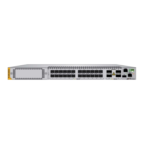
Allied Telesis x950-52XTQm Installation Manual (230 pages)
Standalone Switches, Advanced Layer 3+ AlliedWare Plus
Brand:
Allied Telesis
| Category:
Switch
| Size: 10.52 MB
Table of Contents
Table of Contents
5
Preface
9
Document Conventions
10
Contacting Allied Telesis
11
Chapter 1: Overview
13
X950 Series Switches
14
Features
16
Hardware Features
16
XEM2 Ethernet Line Cards
17
Management Software and Interfaces
17
Management Methods
17
Management Panel
18
Power Supplies
18
Ports for 1Gbps SFP, 10Gbps SFP+, or SP10TM Transceivers
19
SFP and SFP+ Transceivers
19
Leds
20
Twisted Pair Ports on the X950-28Xtqm and X950-52Xtqm Switches
21
Cable Requirements
21
Leds
22
Ports for 40Gbps QSFP+ or 100Gbps QSFP28 Transceivers, or Breakout Cables
24
QSFP28 Transceivers
24
QSFP+ Transceivers
24
Breakout Cables
24
Leds
25
Port Numbering for the X950-28XSQ and X950-28Xtqm Switches
28
Port Numbering for the X950-52XSQ and X950-52Xtqm Switches
29
Management Panel
30
USB Port
31
NET MGMT Ethernet Management Port
31
Console (RS-232) Port
32
Switch ID LED
32
Eco-Friendly Button
34
Optional Direct Attach Cables
35
PWR600 AC and DC Power Supplies
36
Power Supply Airflow and Fan Modules
37
Guidelines for Power Supply
39
PWR600 AC Power Supply
39
Leds
40
PWR600 DC Power Supply
41
Leds
41
FAN05 Cooling Fan
43
FAN05 Airflow and PWR600 Power Supply
43
Guidelines for the Cooling Fan Module
44
Designating Ports in the Command Line Interface
45
Base Ports and Line Card Ports
46
Examples for the PORT Parameter on Base Ports
46
Examples for the PORT Parameter on an XEM2 Line Card
47
Software and Hardware Releases
48
Chapter 2: XEM2 Ethernet Line Cards
49
Overview
50
XEM2-8Xstm Line Card
53
Twisted Pair Ports
53
Twisted Pair Port Leds
54
Transceiver Ports
55
Transceiver Port Leds
56
XEM2-12XT Line Card
57
Twisted Pair Ports
57
Leds
58
XEM2-12Xtm Line Card
59
Twisted Pair Ports
59
Leds
60
XEM2-12XS and XEM2-12XS V2 Line Cards
61
Transceiver Ports
61
Card Versions
62
Leds
62
XEM2-4QS Line Card
64
Transceiver Ports
64
Leds
65
XEM2-1CQ Line Card
66
Transceiver Port
66
Leds
66
Chapter 3: Beginning the Installation
69
Reviewing Safety Precautions
70
Installation Options
75
Choosing a Site for the Chassis
76
Unpacking the Switch
77
Verifying the Accessory Kit
81
Unpacking the PWR600 AC Power Supply
83
Unpacking the PWR600 DC Power Supply
86
Chapter 4: Installing Power Supplies and Optional XEM2 Line Card
87
Installing PWR600 AC Power Supplies
88
Installing PWR600 DC Power Supplies
92
Connecting the Grounding Wire
95
Connecting the DC Power Wires
99
Installing an Optional XEM2 Ethernet Line Card
103
Chapter 5: Installing the Switch on a Table
107
Chapter 6: Installing the Switch in an Equipment Rack
111
Beginning the Installation
112
Required Items
112
Switch Orientations in the Equipment Rack
112
Removing the Bumper Feet
114
Installing the Switch
115
Chapter 7: Installing the Switch on a Wall
119
Switch Orientations on a Wall
120
Recommended Minimum Wall Area Dimensions
121
Plywood Base for a Wall with Wooden Studs
123
Installation Guidelines
125
Tools and Material
126
Installing the Plywood Base
127
Installing the Switch on the Plywood Base
128
Installing the Switch on a Concrete Wall
131
Chapter 8: Installing the Switch in the RKMT-SL01 Sliding Rack
135
Introduction
136
Rack Mount Kit Components
137
Adjustable Outer Rails
137
Inner Rails
137
Extension Brackets
137
Equipment Rack Requirements
139
Reviewing Safety Precautions
140
Installation Overview
143
Unpacking the Shipping Container
144
Installing the Outer Rails on the Equipment Rack
146
Installing the Extension Brackets on the Inner Rails
148
Measuring the Extension Bracket Lengths
148
Assembling the Extension Brackets
150
Installing the Inner Rails on the Switch
154
Installing the Switch in the Equipment Rack
156
Chapter 9: Verifying and Configuring the Switch
159
Powering on the Switch
160
Powering on the PWR600 AC Power Supply
160
Powering on the PWR600 DC Power Supply
162
Starting a Local Management Session
164
Verifying the Switch with Alliedware Plus Commands
166
Disabling Vcstack
167
Configuring Ports for 40Gbps QSFP+ or 100Gbps QSFP28 Transceivers, or Breakout Cables
170
Saving Your Changes and Rebooting the Switch
172
Chapter 10: Cabling the Networking Ports
173
Cabling Twisted Pair Ports
174
Guidelines to Handling Twisted Pair or Fiber Optic Transceivers
175
Installing Transceivers
176
Installing Direct Attach Cables
182
Chapter 11: Replacing Modules
185
Replacing XEM2 Ethernet Line Cards
186
Replacing PWR600 AC Power Supplies
191
Replacing PWR600 DC Power Supplies
196
Replacing FAN05 Modules
199
Removing Fan Modules
199
Installing Fan Modules
201
Chapter 12: Troubleshooting
205
Appendix A: Technical Specifications
211
Physical Specifications
212
Environmental Specifications
216
Power Specifications
217
Certifications
227
Twisted Pair Port Pinouts
228
Style Serial Console Port Pinouts
230
Advertisement
Advertisement
Related Products
Allied Telesis x950-52XSQ
Allied Telesis x950 Series
Allied Telesis x950-28XSQ
Allied Telesis x950-28XTQm
Allied Telesis x900-48FE
Allied Telesis AT x900-48FS
Allied Telesis SwitchBlade x900-24XS
Allied Telesis AT X900-12XT/S
Allied Telesis x930 Series
Allied Telesis SwitchBlade x900-12XS
Allied Telesis Categories
Switch
Network Router
Media Converter
Network Hardware
Wireless Access Point
More Allied Telesis Manuals
Login
Sign In
OR
Sign in with Facebook
Sign in with Google
Upload manual
Upload from disk
Upload from URL