
Subscribe to Our Youtube Channel
Summary of Contents for Innominate mGuard
- Page 1 Configuration of the mGuard Security Appliances Hardware Reference Manual Innominate S e c u r i t y Te c h n o l o g i e s...
- Page 2 Installing and starting up the mGuard hardware 2015-07-24 Designation: UM EN MGUARD DEVICES Revision: Order No.: — This user manual is valid for the following devices of the mGuard product range: – mGuard rs4000/rs2000 – mGuard smart²/smart – rs4000 TX/TX – mGuard pci² SD –...
- Page 3 The receipt of technical documentation (in particular user documentation) does not consti- tute any further duty on the part of Innominate to furnish information on modifications to products and/or technical documentation. You are responsible for verifying the suitability and intended use of the products in your specific application, in particular with regard to ob- serving the applicable standards and regulations.
- Page 4 “Innominate” and “mGuard” are registered trade names of Innominate Security Technolo- gies AG. mGuard technology is protected by patents 10138865 and 10305413, granted by the German Patent and Trademark Office. Further patents are pending. Published by Innominate Security Technologies AG...
- Page 5 Class A: mGuard rs4000, mGuard rs2000, mGuard rs4000 Switch, mGuard rs2000 Switch, mGuard centerport, mGuard industrial rs, mGuard smart², mGuard smart, mGuard pci, mGuard pci² SD, mGuard delta, mGuard delta², and EAGLE mGuard. Class B: mGuard rs4000 3G, mGuard rs2000 3G, mGuard centerport²...
- Page 6 Innominate Security Technologies...
-
Page 7: Table Of Contents
Restart, recovery procedure, and flashing the firmware........27 Technical data .....................31 mGuard rs4000/rs2000 Switch ....................33 Operating elements and LEDs................34 Startup .........................36 Installing the mGuard rs4000/rs2000 Switch ............37 Preparing the configuration..................42 Configuration in Router mode ................42 Establishing a local configuration connection ............43 Remote configuration ..................45 Restart, recovery procedure, and flashing the firmware........46... - Page 8 Technical data .....................90 mGuard pci² SD ........................91 Operating elements and LEDs................92 Startup .........................93 Installation of mGuard pci² SD ................94 Preparing the configuration..................95 Configuration in Stealth mode................96 Establishing a local configuration connection ............101 Remote configuration ..................103 Restart, recovery procedure, and flashing the firmware........104 Technical data ....................107...
- Page 9 10.8 Technical data ....................195 11 mGuard centerport .........................197 11.1 Operating elements and LEDs................198 11.2 Startup .......................199 11.3 Installing and booting mGuard centerport ............200 11.4 Preparing the configuration................204 11.5 Establishing a local configuration connection ............206 11.6 Remote configuration ..................208 11.7 Restart, recovery procedure, and flashing the firmware........209 11.8...
- Page 10 12.9 Technical data ....................235 13 EAGLE mGuard ........................237 13.1 Operating elements and LEDs................238 13.2 Startup .......................239 13.3 Installation of EAGLE mGuard ................240 13.4 Preparing the configuration................243 13.5 Configuration in Stealth mode................244 13.6 Establishing a local configuration connection ............247 13.7 Remote configuration ..................249 13.8...
-
Page 11: Mguard Rs4000/Rs2000
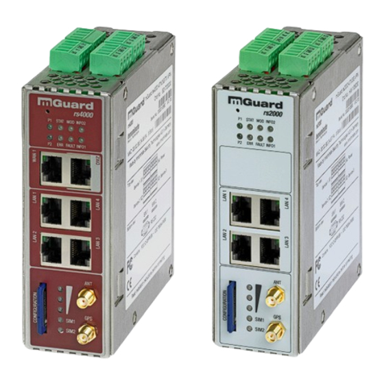
TX/TX VPN HW-108010 The mGuard rs4000 is a security router with intelligent firewall and optional IPsec VPN (10 to 250 tunnels). It has been designed for use in industry to accommodate strict distributed security and high availability requirements. -
Page 12: Operating Elements And Leds
LEDs on the mGuard rs4000 and mGuard rs2000 State Meaning Green On Power supply 1 is active Green On Power supply 2 is active (mGuard rs2000: not used) STAT Green Flashing Heartbeat. The device is correctly connected and operating. Flashing System error. Restart the device. - Page 13 Table 1-2 LEDs on the mGuard rs4000 and mGuard rs2000 [...] State Meaning INFO Green On Up to firmware version 8.0: the configured VPN connection has been established As of firmware version 8.1, the configured VPN connections are established or the...
-
Page 14: Startup
-20°C ... +60°C – Maximum humidity, non-condensing 5% ... 95% To avoid overheating, do not expose the mGuard to direct sunlight or other heat sources. NOTE: Cleaning Clean the device housing with a soft cloth. Do not use aggressive solvents. 1.2.2 Checking the scope of supply Before startup, check the scope of supply to ensure nothing is missing. -
Page 15: Installation Of Mguard Rs4000/Rs2000
Mounting the mGuard rs4000/rs2000 on a DIN rail • Attach the top snap-on foot of the mGuard rs4000/rs2000 to the DIN rail and then press the mGuard rs4000/rs2000 down towards the DIN rail until it engages with a click. Removal •... - Page 16 RJ45 sockets; these must not be connected to the RJ45 sockets of the mGuard. • Connect the mGuard to the network. To do this, you need a suitable UTP cable (CAT5) which is not included in the scope of supply. •...
- Page 17 Alarm output ACK O3 The O3 alarm output monitors the function of the mGuard rs4000/rs2000 and therefore en- ables remote diagnostics. The Fault LED lights up red if the signal output takes low level due to an error (inverted logic).
- Page 18 If the INFO LED is illuminated, the VPN connection is present. If the INFO LED is flashing, the VPN connection is being established or released. Signal contact (signal out- The signal contact monitors the function of the mGuard rs4000/rs2000 and thus enables re- put) mote diagnostics.
- Page 19 Figure 1-4). Status LED P1 lights up green when the supply voltage has been connected properly. On the mGuard rs4000, the status indicator P2 also lights up if there is a redundant supply volt- age connection. The mGuard boots the firmware. Status STAT LED flashes green. The mGuard is ready for operation as soon as the Ethernet socket LEDs light up.
-
Page 20: Preparing The Configuration
1.4.2 Local configuration on startup (EIS) As of firmware version 7.2, initial startup of mGuard products provided in Stealth mode is considerably easier. From this version onwards, the EIS (Easy Initial Setup) procedure en- ables startup to be performed via preset or user-defined management addresses without actually having to connect to an external network. -
Page 21: Configuration In Stealth Mode
Computers can access the mGuard via https://1.1.1.1/ if they are directly or indirectly con- nected to the LAN port of the mGuard. For this purpose, the mGuard with LAN port and WAN port must be integrated in an operational network in which the default gateway can be accessed via the WAN port. - Page 22 This is the case if it is connected in an existing network connection and if the default gateway can be accessed via the WAN port of the mGuard at the same time. In this case, the web browser establishes a connection to the mGuard configuration inter- face after the address https://1.1.1.1/ is entered (see “Establishing a local configuration con-...
- Page 23 After receiving a BootP reply, the mGuard no longer sends BootP requests, not even after it has been restarted. For the mGuard to send BootP requests again, it must either be set to the default settings or one of the procedures (recovery or flash) must be performed.
-
Page 24: Establishing A Local Configuration Connection
If the administrator web page of the mGuard cannot be accessed If you have forgotten the If the address of the mGuard in Router, PPPoE or PPTP mode has been set to a different configured address value, and the current address is not known, the mGuard must be reset to the default set- tings specified above for the IP address using the Recovery procedure (see “Performing a... - Page 25 Password: mGuard The mGuard can then be configured via the web interface. For additional information, please refer to the software reference manual. For security reasons, we recommend you change the default root and administrator pass- words during initial configuration.
-
Page 26: Remote Configuration
Switch on the remote configuration option in the web interface under “Management >> Web Settings”. How to proceed To configure the mGuard via its web user interface from a remote computer, establish the connection to the mGuard from there. Proceed as follows: •... -
Page 27: Restart, Recovery Procedure, And Flashing The Firmware
Restart, recovery procedure, and flashing the firm- ware The Reset button is used to set the device to one of the following states: – Performing a restart – Performing a recovery procedure – Flashing the firmware/rescue procedure Reset button... - Page 28 Stealth https://1.1.1.1/ https://192.168.1.1/ The mGuard is reset to Stealth mode with the default setting “multiple Clients”. – The CIFS integrity monitoring function is also disabled because this only works when the management IP is active. – In addition, MAU management is switched on for Ethernet connections. HTTPS access is enabled via the local Ethernet connection (LAN).
- Page 29 All configured settings are deleted. The mGuard is set to the delivery state. – In Version 5.0.0 or later of the mGuard, the licenses installed on the mGuard are re- tained after flashing the firmware. Therefore, they do not have to be installed again.
- Page 30 To flash the firmware or to perform the rescue procedure, proceed as follows: NOTE: Do not interrupt the power supply to the mGuard during any stage of the flashing procedure. Otherwise, the device could be damaged and may have to be reactivated by the manufacturer.
-
Page 31: Technical Data
Firmware compatibility For mGuard v7.4.0 or later: Innominate recommends the use of the latest firmware ver- sion and patch releases in each case. For the scope of functions, please refer to the relevant firmware data sheet. - Page 32 Innominate Security Technologies I15007_en_02...
-
Page 33: Mguard Rs4000/Rs2000 Switch
VPN router for up to 250 parallel, IPsec-encrypted VPN tunnels. The mGuard rs2000 Switch is a version with basic firewall and can be used as a VPN cli- ent for up to two parallel, IPsec-encrypted VPN tunnels. It is suitable for secure remote maintenance applications and enables connection of globally distributed machines and controllers. -
Page 34: Operating Elements And Leds
Slot for optional SD card RS-232 interface (bottom) Figure 2-2 Operating elements and LEDs on the mGuard rs4000 Switch Table 2-2 LEDs on the mGuard rs4000 Switch and mGuard rs2000 Switch State Meaning Green Power supply 1 is active Green... - Page 35 Switch Table 2-2 LEDs on the mGuard rs4000 Switch and mGuard rs2000 Switch [...] State Meaning Info2 Green The configured VPN connections are established at output O1 or the firewall re- cords defined at output O1 are activated.
-
Page 36: Startup
The scope of supply includes: – Device – Package slip – Plug-in screw terminal blocks for the power supply connection and inputs/outputs (in- serted) 2.2.3 mGuard-Firmware The device must be operated with mGuard-Firmware version 8.1.5 or higher. Innominate Security Technologies I15007_en_02... -
Page 37: Installing The Mguard Rs4000/Rs2000 Switch
Mounting the mGuard rs4000/rs2000 Switch on a DIN rail • Attach the top snap-on foot of the mGuard rs4000/rs2000 Switch to the DIN rail and then press the mGuard rs4000/rs2000 Switch down towards the DIN rail until it engag- es with a click. - Page 38 Switch 2.3.2 Connecting to the network NOTE: Risk of material damage due to incorrect wiring Only connect the device network ports to LAN installations. Some telecommunications connections also use RJ45 sockets; these must not be connected to the RJ45 sockets of the device.
- Page 39 The plug-in screw terminal blocks of the service contacts may be removed or inserted dur- ing operation of the device. The mGuard rs4000/rs2000 Switch has three digital inputs and outputs. These are config- ured in the web interface, e.g., as a control signal for starting and stopping VPN connec- tions.
- Page 40 Alarm output ACK O3 The O3 alarm output monitors the function of the mGuard rs4000/rs2000 and therefore en- ables remote diagnostics. The Fault LED lights up red if the signal output takes low level due to an error (inverted logic).
- Page 41 The P1 status LED lights up green when the supply voltage has been connected properly. On the mGuard rs4000 Switch, the P2 LED also lights up if there is a redundant supply volt- age connection. The device boots the firmware. The Stat LED flashes green. The device is ready for opera- tion as soon as the Ethernet socket LEDs light up.
-
Page 42: Preparing The Configuration
In the Control Panel, open the “Network and Sharing Center”. • Click on “LAN connection”. (The “LAN connection” item is only displayed if a connection exists from the LAN interface on the computer to a mGuard in operation or another part- ner). •... -
Page 43: Establishing A Local Configuration Connection
Switch Establishing a local configuration connection Web-based administrator The device is configured via a web browser that is executed on the configuration computer. interface NOTE: The web browser used must support SSL encryption (i.e., HTTPS). The device can be accessed via the following address:... - Page 44 Switch After successful connection establishment Once a connection has been established successfully, a security alert may be displayed. Explanation As administrative tasks can only be performed using encrypted access, a self-signed certif- icate is supplied with the device.
-
Page 45: Remote Configuration
Switch Remote configuration Requirement The device must be configured so that remote configuration is permitted. By default upon delivery, the option for remote configuration is disabled. Switch on the remote configuration option in the web interface under “Management >> Web Settings”. -
Page 46: Restart, Recovery Procedure, And Flashing The Firmware
Switch Restart, recovery procedure, and flashing the firm- ware The reset button is used to set the device to one of the following states: – Performing a restart – Performing a recovery procedure – Flashing the firmware/rescue procedure... - Page 47 Management IP #1 Management IP #2 Router https://192.168.1.1/ The mGuard is reset to router mode with the fixed IP address. – The CIFS integrity monitoring function is also disabled because this only works when the management IP is active. –...
- Page 48 NOTE: Installing a second DHCP server in a network could affect the configuration of the entire network. – The mGuard firmware has been obtained from your dealer's support team or the www.innominate.com website and has been saved on a compatible SD card.
- Page 49 The mGuard now starts the rescue system: It first searches for an inserted SD card and for the relevant firmware there. If the mGuard does not find an SD card, it searches for a DHCP server via the LAN interface in order to obtain an IP address.
-
Page 50: Technical Data
13 LEDs (Power 1 + 2, State, Error, Signal, Fault, Modem, Info, Signal Status, SIM Sta- tus) | service I/O | log file | remote Syslog Other mGuard rs4000 Switch mGuard rs2000 Switch Special features Realtime clock | Trusted Platform Module (TPM) | temperature sensor | mGuard Se- cure Cloud ready Innominate Security Technologies I15007_en_02... -
Page 51: Mguard Rs4000/Rs2000 3G
VPN router for up to 250 parallel, IPsec-encrypted VPN tunnels. The mGuard rs2000 3G is a version with basic firewall and can be used as a VPN client for up to two parallel, IPsec-encrypted VPN tunnels. It is suitable for secure remote mainte- nance applications at locations without wired networks and enables global connection of distributed machines and controllers. -
Page 52: Operating Elements And Leds
– RSMA (GPS) Figure 3-2 Operating elements and LEDs on the mGuard rs4000 3G Table 3-2 LEDs on the mGuard rs4000 3G and mGuard rs2000 3G State Meaning Green Power supply 1 is active Green Power supply 2 is active (mGuard rs2000 3G: not used) - Page 53 3G Table 3-2 LEDs on the mGuard rs4000 3G and mGuard rs2000 3G [...] State Meaning Info2 Green Up to firmware version 8.0 As of firmware version 8.1 The configured VPN connection has The configured VPN connections are been established at output O1.
-
Page 54: Startup
-40°C ... +60°C – Maximum humidity, non-condensing: 5% ... 95% To avoid overheating, do not expose the mGuard to direct sunlight or other heat sources. NOTE: Cleaning Clean the device housing with a soft cloth. Do not use aggressive solvents. 3.2.2 Checking the scope of supply Before startup, check the scope of supply to ensure nothing is missing. -
Page 55: Installation Of Mguard Rs4000/Rs2000 3G
Mounting the mGuard rs4000/rs2000 3G on a DIN rail • Attach the top snap-on foot of the mGuard rs4000/rs2000 3G to the DIN rail and then press the mGuard rs4000/rs2000 3G down towards the DIN rail until it engages with a click. - Page 56 RJ45 sockets; these must not be connected to the RJ45 sockets of the mGuard. • Connect the mGuard to the network. To do this, you need a suitable UTP cable (CAT5) which is not included in the scope of supply. Use UTP cables with an impedance of 100 Ω.
- Page 57 The plug-in screw terminal blocks of the service contacts may be removed or inserted dur- ing operation of the mGuard. The mGuard rs4000/rs2000 3G has three digital inputs and outputs. These are configured in the web interface, e.g., the starting and stopping of VPN, sending alarms via SMS etc..
- Page 58 Alarm output ACK O3 The O3 alarm output monitors the function of the mGuard rs4000/rs2000 and therefore en- ables remote diagnostics. The Fault LED lights up red if the signal output takes low level due to an error (inverted logic).
- Page 59 If the INFO LED is illuminated, the VPN connection is present. If the INFO LED is flashing, the VPN connection is being established or released. Signal contact (signal out- The signal contact monitors the function of the mGuard rs4000/rs2000 and thus enables re- put) mote diagnostics.
- Page 60 SMA round plug (GSM/UMTS) and R-SMA round plug (TC ANT MOBILE/GPS, 2903590 from Phoenix Contact). In the case of the mGuard rs2000 3G, the WAN is only available via the mobile network, as a WAN interface is not available. The mobile network function is preset. The mGuard rs2000 3G can only be operated in Router mode.
- Page 61 Quality of the mobile network connection The signal strength of the mobile network connection is indicated by three LEDs on the front of the mGuard rs4000/rs2000 3G. The LEDs function as a bar graph (refer to “Bar graph” on page 53).
- Page 62 Status LED P1 lights up green when the supply voltage has been connected properly. On the mGuard rs4000 3G, the status indicator P2 also lights up if there is a redundant supply voltage connection. The mGuard boots the firmware. The Stat LED flashes green. The mGuard is ready for op- eration as soon as the Ethernet socket LEDs light up.
- Page 63 3G If the supply voltage is not redundant, the mGuard rs4000 3G indicates the failure of the supply voltage via the signal contact. This message can be prevented by feeding the supply voltage via both inputs or by installing an appropriate wire jumper between the connections.
-
Page 64: Preparing The Configuration
In the Control Panel, open the “Network and Sharing Center”. • Click on “LAN connection”. (The “LAN connection” item is only displayed if a connection exists from the LAN interface on the computer to a mGuard in operation or another part- ner). •... -
Page 65: Establishing A Local Configuration Connection
If the administrator web page of the mGuard cannot be accessed If you have forgotten the If the address of the mGuard in Router, PPPoE or PPTP mode has been set to a different configured address value, and the current address is not known, the mGuard must be reset to the default set- tings specified above for the IP address using the Recovery procedure (see “Performing a... - Page 66 Password: mGuard The mGuard can then be configured via the web interface. For additional information, please refer to the software reference manual. For security reasons, we recommend you change the default root and administrator pass- words during initial configuration.
-
Page 67: Remote Configuration
Switch on the remote configuration option in the web interface under “Management >> Web Settings”. How to proceed To configure the mGuard via its web user interface from a remote computer, establish the connection to the mGuard from there. Proceed as follows: •... -
Page 68: Restart, Recovery Procedure, And Flashing The Firmware
3G Restart, recovery procedure, and flashing the firm- ware The Reset button is used to set the device to one of the following states: – Performing a restart – Performing a recovery procedure – Flashing the firmware/rescue procedure... - Page 69 Router https://192.168.1.1/ mGuard rs2000 3G Router https://192.168.1.1/ The mGuard is reset to router mode with the fixed IP address. – The CIFS integrity monitoring function is also disabled because this only works when the management IP is active. – In addition, MAU management is switched on for Ethernet connections. HTTPS access is enabled via the local Ethernet connection (LAN).
- Page 70 Flashing the firmware/rescue procedure Objective The entire firmware of the mGuard should be reloaded on the device. – All configured settings are deleted. The mGuard is set to the delivery state. Possible reasons The administrator and root password have been lost. Requirements Requirements for flashing NOTE: During flashing, the firmware is always loaded from an SD card first.
- Page 71 To flash the firmware or to perform the rescue procedure, proceed as follows: NOTE: Do not interrupt the power supply to the mGuard during any stage of the flashing procedure. Otherwise, the device could be damaged and may have to be reactivated by the manufacturer.
-
Page 72: Technical Data
3G mGuard rs2000 3G Firmware compatibility For mGuard v8.0 or later: Innominate recommends the use of the latest firmware ver- sion and patch releases in each case. For the scope of functions, please refer to the relevant firmware data sheet. - Page 73 CE | FCC | UL 508 | electrical isolation (VCC//PE) | ANSI / ISA 12.12 Class I Div. 2 Special features GPS / GLONASS receiver | realtime clock | Trusted Platform Module (TPM) | tempera- ture sensor | mGuard Secure Cloud ready I15007_en_02 Innominate Security Technologies...
- Page 74 3G Innominate Security Technologies I15007_en_02...
-
Page 75: Mguard Delta²
Individual devices or network segments can be safely networked and comprehensively pro- tected. The mGuard delta² can be used as a firewall between office and production net- works as well as a security router for small and medium-sized workgroups. -
Page 76: Operating Elements And Leds
LAN 2 Green 100 Mbps Flash- 100 Mbps, data transmission active Green Supply voltage OK STAT Green Flash- The mGuard is ready to operate. System error FAULT mGuard in the booting or flashing state INFO Not used Innominate Security Technologies I15007_en_02... -
Page 77: Startup
0°C ... +40°C – Maximum humidity, non-condensing: 5% ... 95% To avoid overheating, do not expose the mGuard to direct sunlight or other heat sources. NOTE: Cleaning Clean the device housing with a soft cloth. Do not use aggressive solvents. -
Page 78: Connecting The Mguard Delta²
4.3.1 Connecting to the network • Connect the mGuard to the network. To do this, you need a suitable UTP cable (CAT5) which is not included in the scope of supply. • Connect the internal network interface LAN 1 of the mGuard to the corresponding Ethernet network card of the configuration computer or a valid network connection of the internal network (LAN). -
Page 79: Preparing The Configuration
4.4.2 Local configuration on startup (EIS) As of firmware version 7.2, initial startup of mGuard products provided in Stealth mode is considerably easier. From this version onwards, the EIS (Easy Initial Setup) procedure en- ables startup to be performed via preset or user-defined management addresses without actually having to connect to an external network. -
Page 80: Configuration In Stealth Mode
Computers can access the mGuard via https://1.1.1.1/ if they are directly or indirectly con- nected to the LAN port of the mGuard. For this purpose, the mGuard with LAN port and WAN port must be integrated in an operational network in which the default gateway can be accessed via the WAN port. - Page 81 This is the case if it is connected in an existing network connection and if the default gateway can be accessed via the WAN port of the mGuard at the same time. In this case, the web browser establishes a connection to the mGuard configuration inter- face after the address https://1.1.1.1/ is entered (see “Establishing a local configuration con-...
- Page 82 After receiving a BootP reply, the mGuard no longer sends BootP requests, not even after it has been restarted. For the mGuard to send BootP requests again, it must either be set to the default settings or one of the procedures (recovery or flash) must be performed.
-
Page 83: Establishing A Local Configuration Connection
If the administrator web page of the mGuard cannot be accessed If you have forgotten the If the address of the mGuard in Router, PPPoE or PPTP mode has been set to a different configured address value, and the current address is not known, the mGuard must be reset to the default set- tings specified above for the IP address using the Recovery procedure (see “Performing a... - Page 84 Password: mGuard The mGuard can then be configured via the web interface. For additional information, please refer to the software reference manual. For security reasons, we recommend you change the default root and administrator pass- words during initial configuration.
-
Page 85: Remote Configuration
Switch on the remote configuration option in the web interface under “Management >> Web Settings”. How to proceed To configure the mGuard via its web user interface from a remote computer, establish the connection to the mGuard from there. Proceed as follows: •... -
Page 86: Restart, Recovery Procedure, And Flashing The Firmware
Restart, recovery procedure, and flashing the firm- ware The Reset button is used to set the device to one of the following states: – Performing a restart – Performing a recovery procedure – Flashing the firmware/rescue procedure Reset button... - Page 87 Stealth https://1.1.1.1/ https://192.168.1.1/ The mGuard is reset to Stealth mode with the default setting “multiple Clients”. – The CIFS integrity monitoring function is also disabled because this only works when the management IP is active. – In addition, MAU management is switched on for Ethernet connections. HTTPS access is enabled via the local Ethernet connection (LAN).
- Page 88 All configured settings are deleted. The mGuard is set to the delivery state. – In Version 5.0.0 or later of the mGuard, the licenses installed on the mGuard are re- tained after flashing the firmware. Therefore, they do not have to be installed again.
- Page 89 To flash the firmware or to perform the rescue procedure, proceed as follows: NOTE: Do not interrupt the power supply to the mGuard during any stage of the flashing procedure. Otherwise, the device could be damaged and may have to be reactivated by the manufacturer.
-
Page 90: Technical Data
629 g Firmware and power values Firmware compatibility For mGuard v7.4.0 or later: Innominate recommends the use of the latest firmware version and patch releases in each case. For the scope of functions, please refer to the relevant firmware data sheet. -
Page 91: Mguard Pci² Sd
SD VPN BD-111040 mGuard pcie² SD VPN BD-111060 The mGuard pci² SD has the design of a PCI-compatible plug-in board. It is available in two versions: – mGuard pci² SD for devices or machines with PCI bus –... -
Page 92: Operating Elements And Leds
Boot process. When the device has just been connected to the power supply. After a few seconds, this LED changes to the heartbeat state. Green Flash- Heartbeat. The mGuard is connected correctly and ready to operate. Flash- System error. Restart the device. •... -
Page 93: Startup
0°C ... +70°C (mGuard pci² SD without battery) – Maximum humidity, non-condensing: 5% ... 95% To avoid overheating, do not expose the mGuard to direct sunlight or other heat sources. NOTE: Cleaning Clean the device housing with a soft cloth. Do not use aggressive solvents. 5.2.2 Checking the scope of supply Before startup, check the scope of supply to ensure nothing is missing. -
Page 94: Installation Of Mguard Pci² Sd
Installing the hardware NOTE: Electrostatic discharge Before installation, touch the metal frame of the PC in which the mGuard pci² SD is to be installed, in order to remove electrostatic discharge. The device contains components that can be damaged or destroyed by electrostatic dis- charge. -
Page 95: Preparing The Configuration
5.4.2 Local configuration on startup (EIS) As of firmware version 7.2, initial startup of mGuard products provided in Stealth mode is considerably easier. From this version onwards, the EIS (Easy Initial Setup) procedure en- ables startup to be performed via preset or user-defined management addresses without actually having to connect to an external network. -
Page 96: Configuration In Stealth Mode
The mGuard boots the firmware. The STAT status LED flashes green during this time. The mGuard is ready for operation as soon as the lower Ethernet socket LEDs light up. In addition, the STAT status LED flashes green at heartbeat. - Page 97 The connection to the mGuard pci² SD is established. (If not, see Section 5.5.2). A security message indicating a possible invalid/not trusted certificate is displayed. This message results from the use of an mGuard certificate from Innominate that is not yet known to the browser but necessary for encryption of the communication.
- Page 98 Starting up the mGuard pci² SD via a temporary manage- ment IP address If the mGuard pci² SD is connected without a functioning external network in initial startup mode, the device cannot be accessed via address https://1.1.1.1/. In this case, the mGuard pci² SD is accessible automatically via management IP address 192.168.1.1/24.
- Page 99 5.5.3 Starting up mGuard pci² SD via BootP In initial startup mode, the mGuard pci² additionally starts a BootP client on the internal net- work interface (LAN 1). The BootP client is compatible with the “IPAssign” BootP servers from Phoenix Contact as well as “DHCPD” under Linux.
- Page 100 After receiving a BootP reply, the mGuard no longer sends BootP requests, not even after it has been restarted. For the mGuard to send BootP requests again, it must either be set to the default settings or one of the procedures (recovery or flash) must be performed.
-
Page 101: Establishing A Local Configuration Connection
If the administrator web page of the mGuard cannot be accessed If you have forgotten the If the address of the mGuard in Router, PPPoE or PPTP mode has been set to a different configured address value, and the current address is not known, the mGuard must be reset to the default set- tings specified above for the IP address using the Recovery procedure (see “Performing a... - Page 102 Password: mGuard The mGuard can then be configured via the web interface. For additional information, please refer to the software reference manual. For security reasons, we recommend you change the default root and administrator pass- words during initial configuration.
-
Page 103: Remote Configuration
Switch on the remote configuration option in the web interface under “Management >> Web Settings”. How to proceed To configure the mGuard via its web user interface from a remote computer, establish the connection to the mGuard from there. Proceed as follows: •... -
Page 104: Restart, Recovery Procedure, And Flashing The Firmware
Performing a restart Objective The device is restarted with the configured settings. Action • Press the Reset button until the STAT LED lights up orange. • Alternatively, restart the computer that contains the mGuard pci card. Innominate Security Technologies I15007_en_02... - Page 105 SD Stealth https://1.1.1.1/ https://192.168.1.1/ The mGuard is reset to Stealth mode with the default setting “multiple Clients”. – The CIFS integrity monitoring function is also disabled because this only works when the management IP is active. –...
- Page 106 All configured settings are deleted. The mGuard is set to the delivery state. – In Version 5.0.0 or later of the mGuard, the licenses installed on the mGuard are re- tained after flashing the firmware. Therefore, they do not have to be installed again.
-
Page 107: Technical Data
Redundancy options Optional: VPN | router Power supply 3.3 V or 5 V via PCI (mGuard pci² SD) or PCI Express bus (mGuard pcie² SD) Power consumption Typical, 3.7 W ... 4.2 W Humidity range 5% ... 95% during operation and storage, non-condensing... - Page 108 SD Innominate Security Technologies I15007_en_02...
-
Page 109: Mguard Smart²/Smart
The mGuard smart² is a further development of the mGuard smart. To aid understanding, mGuard smart² is mostly used for the two device versions in this user manual. The proper- ties described also apply to the mGuard smart. Differences from the mGuard smart are in- dicated, if applicable. -
Page 110: Operating Elements And Leds
Can be pressed with a straightened paper clip, LED 1 LED 2 LED 3 for example.) Figure 6-2 Operating elements and LEDs on the mGuard smart² Table 6-2 LEDs on the mGuard smart² State Meaning Green LAN: connection to the network partner is present... -
Page 111: Startup
0°C ... +40°C – Maximum humidity, non-condensing 20% ... 90% To avoid overheating, do not expose the mGuard to direct sunlight or other heat sources. NOTE: Cleaning Clean the device housing with a soft cloth. Do not use aggressive solvents. 6.2.2 Checking the scope of supply Before startup, check the scope of supply to ensure nothing is missing. -
Page 112: Connecting The Mguard Smart²
Figure 6-3 mGuard smart²: Connection in the network If your computer is already connected to a network, insert the mGuard smart² between the network interface of the computer (i.e., its network card) and the network. Driver installation is not required. -
Page 113: Preparing The Configuration
6.4.1 Connection requirements – The mGuard smart² must be switched on, i.e., it must be connected to a computer (or power supply unit) that is switched on via a USB cable in order for it to be supplied with power. -
Page 114: Configuration In Stealth Mode
Computers can access the mGuard via https://1.1.1.1/ if they are directly or indirectly con- nected to the LAN port of the mGuard. For this purpose, the mGuard with LAN port and WAN port must be integrated in an operational network in which the default gateway can be accessed via the WAN port. - Page 115 This is the case if it is connected in an existing network connection and if the default gateway can be accessed via the WAN port of the mGuard at the same time. In this case, the web browser establishes a connection to the mGuard configuration inter- face after the address https://1.1.1.1/ is entered (see “Establishing a local configuration con-...
- Page 116 After receiving a BootP reply, the mGuard no longer sends BootP requests, not even after it has been restarted. For the mGuard to send BootP requests again, it must either be set to the default settings or one of the procedures (recovery or flash) must be performed.
-
Page 117: Establishing A Local Configuration Connection
If the administrator web page of the mGuard cannot be accessed If you have forgotten the If the address of the mGuard in Router, PPPoE or PPTP mode has been set to a different configured address value, and the current address is not known, the mGuard must be reset to the default set- tings specified above for the IP address using the Recovery procedure (see “Performing a... - Page 118 Password: mGuard The mGuard can then be configured via the web interface. For additional information, please refer to the software reference manual. For security reasons, we recommend you change the default root and administrator pass- words during initial configuration.
-
Page 119: Remote Configuration
Switch on the remote configuration option in the web interface under “Management >> Web Settings”. How to proceed To configure the mGuard via its web user interface from a remote computer, establish the connection to the mGuard from there. Proceed as follows: •... -
Page 120: Restart, Recovery Procedure, And Flashing The Firmware
Restart, recovery procedure, and flashing the firm- ware The Reset button is used to set the device to one of the following states: – Performing a restart – Performing a recovery procedure – Flashing the firmware/rescue procedure Reset button (Located in the opening. - Page 121 Stealth https://1.1.1.1/ https://192.168.1.1/ The mGuard is reset to Stealth mode with the default setting “multiple Clients”. – The CIFS integrity monitoring function is also disabled because this only works when the management IP is active. – In addition, MAU management is switched on for Ethernet connections. HTTPS access is enabled via the local Ethernet connection (LAN).
- Page 122 Otherwise, the device could be damaged and may have to be reactivated by the manufacturer. • Hold down the Reset button until the LEDs light up green. Then, the mGuard is in the recovery state. • Release the Reset button within a second of entering the recovery state.
-
Page 123: Technical Data
Firmware and power values Firmware compatibility For mGuard v7.2 or later: Innominate recommends the use of the latest firm- ware version and patch releases in each case. For the scope of functions, please refer to the relevant firmware data sheet. - Page 124 158 g Firmware and power values Firmware compatibility mGuard v5.0 or later: Innominate recommends firmware version 6.x or 7.x to be used with the latest patch releases; For the scope of functions, please refer to the relevant firmware data sheet.
-
Page 125: Mguard Centerport²
VPN 1000 BD-622000 The mGuard centerport² is a high-end firewall and a VPN gateway in 19" format. It is suit- able as a central network infrastructure for remote service solutions. With its Gigabit Ether- net interfaces and corresponding throughput as the router and as the stateful inspection fire- wall, the device can also be used in the backbone in industrial networks. -
Page 126: Operating Elements And Leds
USB ports Display SD card slot 19" angled connector 19" angled connector Figure 7-2 Operating elements and LEDs on the mGuard centerport² front side Table 7-2 LEDs on the mGuard centerport² State Meaning Green Lights up if the system is switched on... -
Page 127: Startup
Maximum humidity, non-condensing: 20% ... 90% To avoid overheating, do not expose the mGuard to direct sunlight or other heat sources. NOTE: Risk of material damage caused by cleaning agents Clean the device housing with a soft cloth. Do not use aggressive solvents. -
Page 128: Installing And Booting The Mguard Centerport²
Installing and booting the mGuard centerport² Back IPMI port 4 x USB Ethernet (10/100/1000 Base-TX) (WAN | LAN | SYNC | DMZ ports) 2 x power supply/mains input socket, redun- Serial interface VGA port dant wide-range AC power supply unit... - Page 129 Use a UTP cable (CAT5). • Connect the SYNC port of the device to the SYNC port of a second mGuard centerport² in order to create a redundancy pair. A redundancy license for the second mGuard centerport² must be purchased separately.
- Page 130 To configure the mGuard via the serial interface. There are two options: – A PC is connected directly to the serial interface of the mGuard (via the serial interface of the PC). The PC user can then use a terminal program to configure the mGuard via the command line. –...
- Page 131 This menu item is only to be used in special cases when the user has the appropriate knowledge or upon instruction from the dealer support team. The mGuard firmware checks and repairs the file systems, if required, even during the normal startup process.
-
Page 132: Preparing The Configuration
In the Control Panel, open the “Network and Sharing Center”. • Click on “LAN connection”. (The “LAN connection” item is only displayed if a connection exists from the LAN interface on the computer to a mGuard in operation or another part- ner). •... -
Page 133: Establishing A Local Configuration Connection
If the administrator web page of the mGuard cannot be accessed If you have forgotten the If the address of the mGuard in Router, PPPoE or PPTP mode has been set to a different configured address value, and the current address is not known, the mGuard must be reset to the default set- tings specified above for the IP address using the Recovery procedure (see “Performing a... - Page 134 UserName: admin Password: mGuard The mGuard can then be configured via the web interface. For additional information, please refer to software reference manual. For security reasons, we recommend you change the default root and administrator pass- words during initial configuration.
-
Page 135: Remote Configuration
Switch on the remote configuration option in the web interface under “Management >> Web Settings”. How to proceed To configure the mGuard via its web user interface from a remote computer, establish the connection to the mGuard from there. Proceed as follows: •... -
Page 136: Restart, Recovery Procedure, And Flashing The Firmware
The settings configured for VPN connections and the firewall are retained, including passwords. NOTE: After the recovery procedure has been performed successfully, a previously cre- ated configuration profile in the mGuard should be loaded and activated again. Then the network settings must be adapted. Possible reasons for performing the recovery procedure: –... - Page 137 All configured settings are deleted. The mGuard is set to the delivery state. – In Version 5.0.0 or later of the mGuard, the licenses installed on the mGuard are re- tained after flashing the firmware. Therefore, they do not have to be installed again.
- Page 138 NOTE: All configured settings are deleted. The mGuard is set to the delivery state. In Version 5.0.0 or later of the mGuard, the licenses installed on the mGuard are retained after flashing the firmware. Therefore, they do not have to be installed again.
- Page 139 Once the rescue procedure is complete, a corresponding message appears on the monitor. Follow any further on-screen instructions. Start rescue procedure from USB stick (USB Flash drive) Requirement: The firmware of the mGuard has been previously copied to a USB stor- age medium (USB stick, USB Flash drive). /Firmware/install.x86_64.p7s /Firmware/firmware.img.x86_64.p7s...
- Page 140 133): Burning the mGuard firmware to CD/DVD-ROM The firmware for the mGuard can be burnt to CD/DVD. A zip file is available for download from the download page of www.innominate.com. Burn the content of this zip archive as a data CD/DVD. The following files must be located in the following folders/under the following path names on the CD/DVD: –...
-
Page 141: Technical Data
Firmware and power values Firmware compatibility mGuard v8.1.2 or later; Innominate recommends using the latest patch releases; For the scope of functions, please refer to the relevant firmware data sheet. Data throughput (router | firewall) 2,000 Mbps bidirectional | 2,000 Mbps bidirectional When using the DMZ as independent network zone, the maximum possible data throughput is distributed to the three zones. - Page 142 Innominate Security Technologies I15007_en_02...
-
Page 143: Mguard Delta
An additional serial interface enables configuration via a telephone dial-up connection or a terminal. With its robust metal housing, the mGuard delta is suitable for installation in distri- bution compartments as well as for use as a desktop device. -
Page 144: Operating Elements And Leds
Operating elements and LEDs Current Status Reserved Ethernet WAN Ethernet LAN Figure 8-2 Operating elements and LEDs on the mGuard delta Table 8-2 LEDs on the mGuard delta State Meaning Power The power supply is active. Status The mGuard starts. -
Page 145: Startup
0°C ... +40°C – Maximum humidity, non-condensing: 5% ... 95% To avoid overheating, do not expose the mGuard to direct sunlight or other heat sources. NOTE: Cleaning Clean the device housing with a soft cloth. Do not use aggressive solvents. -
Page 146: Connecting The Mguard Delta
Connect the power supply (5 V DC, 3 A) to the “DC +5V, 3A” socket of the mGuard delta. – Connect the local computer or the local network to one of the Ethernet LAN connections (4 to 7) of the mGuard delta using a UTP Ethernet cable (CAT5). Innominate Security Technologies I15007_en_02... -
Page 147: Preparing The Configuration
The mGuard delta must be connected to its power supply. – For local configuration: The computer used for configuration: – Must be connected to the LAN switch (Ethernet socket 4 to 7) of the mGuard, – Or must be connected to the mGuard via the local network. –... - Page 148 In the Control Panel, open the “Network and Sharing Center”. • Click on “LAN connection”. (The “LAN connection” item is only displayed if a connection exists from the LAN interface on the computer to a mGuard in operation or another part- ner). •...
-
Page 149: Establishing A Local Configuration Connection
If the administrator web page of the mGuard cannot be accessed If you have forgotten the If the address of the mGuard in Router, PPPoE or PPTP mode has been set to a different configured address value, and the current address is not known, the mGuard must be reset to the default set- tings specified above for the IP address using the Recovery procedure (see “Performing a... - Page 150 Password: mGuard The mGuard can then be configured via the web interface. For additional information, please refer to the software reference manual. For security reasons, we recommend you change the default root and administrator pass- words during initial configuration.
-
Page 151: Remote Configuration
Switch on the remote configuration option in the web interface under “Management >> Web Settings”. How to proceed To configure the mGuard via its web user interface from a remote computer, establish the connection to the mGuard from there. Proceed as follows: •... -
Page 152: Restart, Recovery Procedure, And Flashing The Firmware
Restart, recovery procedure, and flashing the firm- ware The Reset button is used to set the device to one of the following states: – Performing a restart – Performing a recovery procedure – Flashing the firmware/rescue procedure Reset button... - Page 153 – The mGuard is in PPPoE mode. – The configured device address of the mGuard differs from the default setting. – The current IP address of the device is not known. Up-to-date information on the recovery and flashing procedure can be found in the appli- cation note for your mGuard firmware version.
- Page 154 All configured settings are deleted. The mGuard is set to the delivery state. – In Version 5.0.0 or later of the mGuard, the licenses installed on the mGuard are re- tained after flashing the firmware. Therefore, they do not have to be installed again.
-
Page 155: Technical Data
1300 g Firmware and power values Firmware compatibility mGuard v5.0 or later: Innominate recommends firmware version 6.x or 7.x to be used with the latest patch releases; For the scope of functions, please refer to the relevant firmware data sheet. - Page 156 Innominate Security Technologies I15007_en_02...
-
Page 157: Mguard Pci
BD-111020 mGuard pci / 266 VPN BD-111010 The mGuard pci is a card which can be inserted into a PCI slot and operated in two modes. – In driver mode, the mGuard pci provides the computer in which the card is installed with all mGuard functions, as well as acting as a normal network card. -
Page 158: Operating Elements And Leds
Recovery mode. After pressing the Reset button*. light codes See “Restart, recovery procedure, and flashing the firmware” on page 175 Green * On the mGuard pci, the Reset button is on the PCB (see “Installing the hardware” on page 164). Innominate Security Technologies I15007_en_02... -
Page 159: Startup
0°C ... +70°C – Maximum humidity, non-condensing: 20% ... 90% To avoid overheating, do not expose the mGuard to direct sunlight or other heat sources. NOTE: Cleaning Clean the device housing with a soft cloth. Do not use aggressive solvents. 9.2.2 Checking the scope of supply Before startup, check the scope of supply to ensure nothing is missing. -
Page 160: Installation Of Mguard Pci
The mGuard is set to the desired mode using a jumper. Driver mode The mGuard pci can be used as a normal network card. This network card then also pro- vides mGuard functions. In this case, the supplied driver must be installed. - Page 161 The IP address that is configured for the network interface of the operating system (LAN port) is also used by the mGuard for its WAN port. This means that the mGuard does not appear as a separate device with its own address for data traffic to and from the computer.
- Page 162 192.168.1.1). (This relationship is shown in the above diagram by two black spheres.) A third IP address is used for the interface of the mGuard to the WAN. It is used for connec- tion to an external network (e.g., Internet).
- Page 163 IP address of the mGuard (by default upon delivery this is 192.168.1.1). A third IP address is used for the interface of the mGuard to the WAN. It is used for connec- tion to an external network (e.g., Internet).
- Page 164 Installing the hardware NOTE: Electrostatic discharge Before installation, touch the metal frame of the PC in which the mGuard pci is to be in- stalled, in order to remove electrostatic discharge. The device contains components that can be damaged or destroyed by electrostatic dis- charge.
- Page 165 Keep the screw for securing the mGuard pci card. • Carefully align the pin strip of the mGuard pci card over the socket strip of the PCI slot on the motherboard and then press the card evenly into the socket strip.
- Page 166 Under Windows XP • After installing the hardware, switch on the computer. • Log on with administrator rights and wait until the following window appears: Figure 9-8 Driver installation under Windows XP After inserting the data carrier, select the “Install from a list or specific location (Ad- vanced)”...
- Page 167 Under Windows 2000 • After installing the hardware, switch on the computer. • Log on with administrator rights and wait until the following window appears: Figure 9-9 Driver installation under Windows 2000 (1) Click “Next”. Select “Search for a suitable driver for my device (recommended)” and click “Next”.
- Page 168 Extract the drivers from the ZIP to the directory /usr/src/pci-driver – Execute the following commands: cd /usr/src/pci-driver make LINUXDIR=/usr/src/linux install -m0644 mguard.o /lib/modules/2.4.25/kernel/drivers/net/ depmod -a – The driver can now be loaded with the following command: modprobe mguard Innominate Security Technologies...
-
Page 169: Preparing The Configuration
9.4.2 Local configuration on startup (EIS) As of firmware version 7.2, initial startup of mGuard products provided in Stealth mode is considerably easier. From this version onwards, the EIS (Easy Initial Setup) procedure en- ables startup to be performed via preset or user-defined management addresses without actually having to connect to an external network. -
Page 170: Configuration In Stealth Mode
“Installing the hardware” on page 164. Installing the drivers • If you have configured the mGuard for Driver mode, make sure that the drivers are in- stalled as described under “Installing drivers” on page 165. Configuring the network interface If the mGuard –... - Page 171 After configuration, reset the default gateway. To do this, either restart the configuration computer or enter the following command in DOS: arp -d Depending on the configuration of the mGuard, it may then be necessary to adapt the net- work interface of the locally connected computer or network accordingly. I15007_en_02...
-
Page 172: Establishing A Local Configuration Connection
If the administrator web page of the mGuard cannot be accessed If you have forgotten the If the address of the mGuard in Router, PPPoE or PPTP mode has been set to a different configured address value, and the current address is not known, the mGuard must be reset to the default set- tings specified above for the IP address using the Recovery procedure (see “Performing a... - Page 173 Password: mGuard The mGuard can then be configured via the web interface. For additional information, please refer to the software reference manual. For security reasons, we recommend you change the default root and administrator pass- words during initial configuration.
-
Page 174: Remote Configuration
Switch on the remote configuration option in the web interface under “Management >> Web Settings”. How to proceed To configure the mGuard via its web user interface from a remote computer, establish the connection to the mGuard from there. Proceed as follows: •... -
Page 175: Restart, Recovery Procedure, And Flashing The Firmware
Performing a restart Objective The device is restarted with the configured settings. Action • Press the Reset button for around 1.5 seconds until both red LEDs light up. Alternatively, restart the computer that contains the mGuard pci card. I15007_en_02 Innominate Security Technologies... - Page 176 Stealth https://1.1.1.1/ https://192.168.1.1/ The mGuard is reset to Stealth mode with the default setting “multiple Clients”. – The CIFS integrity monitoring function is also disabled because this only works when the management IP is active. – In addition, MAU management is switched on for Ethernet connections. HTTPS access is enabled via the local Ethernet connection (LAN).
- Page 177 All configured settings are deleted. The mGuard is set to the delivery state. – In Version 5.0.0 or later of the mGuard, the licenses installed on the mGuard are re- tained after flashing the firmware. Therefore, they do not have to be installed again.
- Page 178 Action NOTE: Do not interrupt the power supply to the mGuard during any stage of the flashing procedure. Otherwise, the device could be damaged and may have to be reactivated by the manufacturer. • Hold down the Reset button until the green LEDs and the red LAN LED light up. Then, the mGuard is in the recovery state.
-
Page 179: Technical Data
72 g Firmware and power values Firmware compatibility mGuard v5.0 or later: Innominate recommends firmware version 6.x or 7.x to be used with the latest patch releases; For the scope of functions, please refer to the relevant firmware data sheet. - Page 180 Innominate Security Technologies I15007_en_02...
-
Page 181: 10 Mguard Blade
/ 266 HW-104820 The mGuard blade consists of the mGuard bladebase, which can be built into standard 3- U racks (19 inch) without problems and accommodate up to 12 mGuard blades and one mGuard blade controller. This device version is therefore ideal for use in industrial applica- tions, where several server systems can be protected individually and independently of one another. -
Page 182: Operating Elements And Leds
Operating elements and LEDs Serial WAN red WAN green LAN red LAN green Reset button Figure 10-2 Operating elements and LEDs on the mGuard blade Table 10-2 mGuard blade State Meaning WAN, LAN Flashing Boot process. When the computer is started or restarted. -
Page 183: Startup
+5°C ... +40°C – Maximum humidity, non-condensing: 10% ... 95% To avoid overheating, do not expose the mGuard to direct sunlight or other heat sources. NOTE: Cleaning Clean the device housing with a soft cloth. Do not use aggressive solvents. 10.2.2 Checking the scope of supply Before startup, check the scope of supply to ensure nothing is missing. -
Page 184: Installation Of Mguard Blade
The mGuard bladebase does not have to be switched off when installing or removing an mGuard blade. – Loosen the top and bottom screw on the faceplate or on the mGuard blade to be re- placed. – Remove the faceplate or pull out the old mGuard blade. - Page 185 Please note that configuration can only be completed from the local computer via the LAN interface and that the firewall of the mGuard blocks all IP data traffic from the WAN to the LAN interface.
- Page 186 To configure the mGuard via the serial interface. There are two options: – A PC is connected directly to the serial interface of the mGuard (via the serial interface of the PC). The PC user can then use a terminal program to configure the mGuard via the command line. –...
-
Page 187: Preparing The Configuration
Preparing the configuration 10.4.1 Connection requirements – The mGuard blade must be mounted in the mGuard bladebase and at least one of the bladebase device's power supply units must be in operation. – For local configuration: The computer used for configuration: –... - Page 188 In the Control Panel, open the “Network and Sharing Center”. • Click on “LAN connection”. (The “LAN connection” item is only displayed if a connection exists from the LAN interface on the computer to a mGuard in operation or another part- ner). •...
-
Page 189: Establishing A Local Configuration Connection
If the administrator web page of the mGuard cannot be accessed If you have forgotten the If the address of the mGuard in Router, PPPoE or PPTP mode has been set to a different configured address value, and the current address is not known, the mGuard must be reset to the default set- tings specified above for the IP address using the Recovery procedure (see “Performing a... - Page 190 Password: mGuard The mGuard can then be configured via the web interface. For additional information, please refer to the software reference manual. For security reasons, we recommend you change the default root and administrator pass- words during initial configuration.
-
Page 191: Remote Configuration
Switch on the remote configuration option in the web interface under “Management >> Web Settings”. How to proceed To configure the mGuard via its web user interface from a remote computer, establish the connection to the mGuard from there. Proceed as follows: •... -
Page 192: Restart, Recovery Procedure, And Flashing The Firmware
10.7 Restart, recovery procedure, and flashing the firm- ware The Reset button is used to set the device to one of the following states: – Performing a restart – Performing a recovery procedure – Flashing the firmware/rescue procedure... - Page 193 – The mGuard is in PPPoE mode. – The configured device address of the mGuard differs from the default setting. – The current IP address of the device is not known. Up-to-date information on the recovery and flashing procedure can be found in the appli- cation note for your mGuard firmware version.
- Page 194 All configured settings are deleted. The mGuard is set to the delivery state. – In Version 5.0.0 or later of the mGuard, the licenses installed on the mGuard are re- tained after flashing the firmware. Therefore, they do not have to be installed again.
-
Page 195: Technical Data
245 g | bladepack: 7.7 kg Firmware and power values Firmware compatibility mGuard v5.0 or later: Innominate recommends firmware version 6.x or 7.x to be used with the latest patch releases; For the scope of functions, please refer to the relevant firmware data sheet. - Page 196 Innominate Security Technologies I15007_en_02...
-
Page 197: 11 Mguard Centerport
VPN-1000 BD-602000 The mGuard centerport is a high-end firewall and a VPN gateway in 19" format. It is suit- able as a central network infrastructure for remote service solutions, With its Gigabit Ether- net interfaces and corresponding throughput as the router and as the stateful inspection fire- wall, the device can also be used in the backbone in industrial networks. -
Page 198: Operating Elements And Leds
Power LED (green) Hard disk activity LED (orange) Interlocking lock, front flap 19" angled connector 19" angled connector Figure 11-2 Operating elements and LEDs on the mGuard centerport front side Table 11-2 LEDs on the mGuard centerport State Meaning Green... -
Page 199: Startup
0°C ... +40°C – Maximum humidity, non-condensing: 5% ... 95% To avoid overheating, do not expose the mGuard to direct sunlight or other heat sources. NOTE: Cleaning Clean the device housing with a soft cloth. Do not use aggressive solvents. 11.2.2 Checking the scope of supply Before startup, check the scope of supply to ensure nothing is missing. -
Page 200: Installing And Booting Mguard Centerport
Connect a PC keyboard to one of the USB connections (not supplied as standard). The monitor and keyboard must only be connected – in order to use one of the boot options upon starting (booting) mGuard centerport - see “Boot options - when monitor and keyboard are connected” on page 202, –... - Page 201 Some telecommunications connections also use RJ45 sockets; these must not be con- nected to the RJ45 sockets of the mGuard. LAN port • Connect the local computer or the local network to the LAN port of the mGuard using a UTP Ethernet cable (CAT5). WAN port •...
- Page 202 ON/OFF switch. Ensure that you keep safe hold of the two keys providedHousing The mGuard centerport housing is from Kontron and is referred to as the KISS 2U platform. Visit www.kontron.de for more information on the following: –...
- Page 203 This menu item is only to be used in special cases when the user has the appropriate knowledge or upon instruction from the dealer support team. The mGuard firmware checks and repairs the file systems, if required, even during the normal startup process.
-
Page 204: Preparing The Configuration
11.4.2 Local configuration on startup (EIS) As of firmware version 7.2, initial startup of mGuard products provided in Stealth mode is considerably easier. From this version onwards, the EIS (Easy Initial Setup) procedure en- ables startup to be performed via preset or user-defined management addresses without actually having to connect to an external network. - Page 205 In the Control Panel, open the “Network and Sharing Center”. • Click on “LAN connection”. (The “LAN connection” item is only displayed if a connection exists from the LAN interface on the computer to a mGuard in operation or another part- ner). •...
-
Page 206: Establishing A Local Configuration Connection
If the administrator web page of the mGuard cannot be accessed If you have forgotten the If the address of the mGuard in Router, PPPoE or PPTP mode has been set to a different configured address value, and the current address is not known, the mGuard must be reset to the default set- tings specified above for the IP address using the Recovery procedure (see “Performing a... - Page 207 Password: mGuard The mGuard can then be configured via the web interface. For additional information, please refer to the software reference manual. For security reasons, we recommend you change the default root and administrator pass- words during initial configuration.
-
Page 208: Remote Configuration
Switch on the remote configuration option in the web interface under “Management >> Web Settings”. How to proceed To configure the mGuard via its web user interface from a remote computer, establish the connection to the mGuard from there. Proceed as follows: •... -
Page 209: Restart, Recovery Procedure, And Flashing The Firmware
Restart, recovery procedure, and flashing the firm- ware For mGuard centerport, there is a reset key which can be used to perform a restart. The res- cue procedure and therefore the reloading of mGuard firmware is initiated via the boot menu. - Page 210 – The mGuard is in PPPoE mode. – The configured device address of the mGuard differs from the default setting. – The current IP address of the device is not known. Up-to-date information on the recovery and flashing procedure can be found in the appli- cation note for your mGuard firmware version.
- Page 211 All configured settings are deleted. The mGuard is set to the delivery state. – In Version 5.0.0 or later of the mGuard, the licenses installed on the mGuard are re- tained after flashing the firmware. Therefore, they do not have to be installed again.
- Page 212 206): Burning mGuard firmware to CD-ROM The firmware for the mGuard can be burnt to CD. A zip file is available for download from the download page of www.innominate.com. The content of this zip archive can be burnt as a data CD. The following files must be located in the following folders/under the following path names on the CD: –...
- Page 213 – Firmware/firmware.img.x86_64.p7s In the case of the file install.x86_64.p7s, ensure that the file version that Innominate has de- clared for use for the rescue procedure via CD is used. If required, these files can be made available in the Rescue Config folder on the CD: Rescue Config/licence.lic...
-
Page 214: Technical Data
10 kg Firmware and power values Firmware compatibility mGuard 7.1 or later: Innominate recommends using the latest patch releases; For the scope of functions, please refer to the relevant firmware data sheet. Data throughput (router | firewall) 2000 Mbps bidirectional | 2000 Mbps bidirectional... -
Page 215: 12 Mguard Industrial Rs
VPN Analog BD-501010 mGuard industrial rs VPN ISDN BD-501020 The mGuard industrial rs can be used as a firewall/VPN router via Ethernet or via serial dial-up connections. It is available in three device versions: – With integrated modem –... -
Page 216: Operating Elements And Leds
ISDN or telephone connection See “Restart, recovery procedure, (see Section 12.2, “Startup”) and flashing the firmware” on page 232. Figure 12-2 Operating elements and LEDs on the mGuard industrial rs Table 12-2 LEDs on the mGuard industrial rs State Meaning Green... -
Page 217: Startup
0°C ... +55°C – Maximum humidity, non-condensing: 10% ... 95% To avoid overheating, do not expose the mGuard to direct sunlight or other heat sources. NOTE: Cleaning Clean the device housing with a soft cloth. Do not use aggressive solvents. 12.2.2 Checking the scope of supply Before startup, check the scope of supply to ensure nothing is missing. -
Page 218: Installation Of Mguard Industrial Rs
• Pull out the terminal block from the bottom of the mGuard industrial rs and wire the sig- nal lines and other connections as required (see “Connection options on the lower ter- minal block” on page 220). - Page 219 Some telecommunications connections also use RJ45 sockets; these must not be con- nected to the RJ45 sockets of the mGuard. LAN port • Connect the local computer or the local network to the LAN port of the mGuard using a UTP Ethernet cable (CAT5). I15007_en_02 Innominate Security Technologies...
- Page 220 Please note that configuration can only be completed via the LAN interface and that the firewall of the mGuard industrial rs blocks all IP data traffic from the WAN to the LAN in- terface. WAN port •...
- Page 221 Button or on/off switch Signal LED (20 mA) Service contacts: , CMD, ACK (for establishing a predefined VPN connection) Figure 12-6 mGuard industrial rs: Without modem/ISDN terminal adapter Lower area on front plate with terminal strip Telephone line Signal contact...
- Page 222 The functional earth ground can be used by the operator. This connection is electrically con- nected to the back of the mGuard industrial rs. The mGuard industrial rs is grounded when it is mounted on a DIN rail with the metal clamp, which connects the back of the device to the DIN rail.
- Page 223 Contacts TX+, TX-, RX+, and RX- are designed for connection to ISDN and identify the mGuard industrial rs as a device in the ISDN network. The table below describes the as- signment of the contacts to 8-pos. connections both for plugs and for sockets, for example...
- Page 224 – A PC is connected directly to the serial interface of the mGuard (via the serial interface of the PC). The PC user can then use a terminal program to configure the mGuard via the command line. –...
-
Page 225: Preparing The Configuration
12.4.1 Connection requirements – The mGuard industrial rs must be connected to at least one active power supply unit. – For local configuration: The computer that is to be used for configuration must be connected to the LAN socket on the mGuard. -
Page 226: Configuration In Stealth Mode
Computers can access the mGuard via https://1.1.1.1/ if they are directly or indirectly con- nected to the LAN port of the mGuard. For this purpose, the mGuard with LAN port and WAN port must be integrated in an operational network in which the default gateway can be accessed via the WAN port. - Page 227 This is the case if it is connected in an existing network connection and if the default gateway can be accessed via the WAN port of the mGuard at the same time. In this case, the web browser establishes a connection to the mGuard configuration inter- face after the address https://1.1.1.1/ is entered (see “Establishing a local configuration con-...
- Page 228 After receiving a BootP reply, the mGuard no longer sends BootP requests, not even after it has been restarted. For the mGuard to send BootP requests again, it must either be set to the default settings or one of the procedures (recovery or flash) must be performed.
-
Page 229: Establishing A Local Configuration Connection
If the administrator web page of the mGuard cannot be accessed If you have forgotten the If the address of the mGuard in Router, PPPoE or PPTP mode has been set to a different configured address value, and the current address is not known, the mGuard must be reset to the default set- tings specified above for the IP address using the Recovery procedure (see “Performing a... - Page 230 Password: mGuard The mGuard can then be configured via the web interface. For additional information, please refer to the software reference manual. For security reasons, we recommend you change the default root and administrator pass- words during initial configuration.
-
Page 231: Remote Configuration
Switch on the remote configuration option in the web interface under “Management >> Web Settings”. How to proceed To configure the mGuard via its web user interface from a remote computer, establish the connection to the mGuard from there. Proceed as follows: •... -
Page 232: Restart, Recovery Procedure, And Flashing The Firmware
12.8 Restart, recovery procedure, and flashing the firm- ware The Reset button is used to set the device to one of the following states: – Performing a restart – Performing a recovery procedure – Flashing the firmware/rescue procedure Reset button Located in the opening. - Page 233 Stealth https://1.1.1.1/ https://192.168.1.1/ The mGuard is reset to Stealth mode with the default setting “multiple Clients”. – The CIFS integrity monitoring function is also disabled because this only works when the management IP is active. –...
- Page 234 All configured settings are deleted. The mGuard is set to the delivery state. – In Version 5.0.0 or later of the mGuard, the licenses installed on the mGuard are re- tained after flashing the firmware. Therefore, they do not have to be installed again.
- Page 235 250 g Firmware and power values Firmware compatibility mGuard v5.0 or later: Innominate recommends firmware version 6.x or 7.x to be used with the latest patch releases; For the scope of functions, please refer to the relevant firmware data sheet.
- Page 236 Innominate Security Technologies I15007_en_02...
-
Page 237: Eagle Mguard
HW-201000 EAGLE mGuard VPN BD-301010 The EAGLE mGuard is designed for DIN rail mounting (according to DIN EN 60715) and is therefore ideal for use in industrial applications. The optional configuration connection and option to establish a phone dial-up connection via the RS-232 interface open up a wealth of applications. -
Page 238: Operating Elements And Leds
Link status/data 2 (WAN) Ethernet LAN Reset button Ethernet WAN Serial V.24 Ground connection Figure 13-2 Operating elements and LEDs on the EAGLE mGuard Table 13-2 LEDs on the EAGLE mGuard State Meaning P1, P2 Green On Power supply 1 or 2 is active. -
Page 239: Startup
0°C ... +60°C – Maximum humidity, non-condensing: 10% ... 95% To avoid overheating, do not expose the mGuard to direct sunlight or other heat sources. NOTE: Cleaning Clean the device housing with a soft cloth. Do not use aggressive solvents. 13.2.2 Checking the scope of supply Before startup, check the scope of supply to ensure nothing is missing. -
Page 240: Installation Of Eagle Mguard
The EAGLE mGuard can be operated at a DC voltage of 9.6 ... 60 V DC, max. 1 A optionally at an AC voltage of 18 ... 30 V AC, max. 1 A. Use the +24 V and 0 V pins to connect the AC voltage. - Page 241 To configure the mGuard via the serial interface. There are two options: – A PC is connected directly to the serial interface of the mGuard (via the serial interface of the PC). The PC user can then use a terminal program to configure the mGuard via the command line. –...
- Page 242 Figure 13-5 EAGLE mGuard: DIN rail mounting • Attach the top snap-on foot of the EAGLE mGuard to the DIN rail and then press the EAGLE mGuard down towards the DIN rail until it engages with a click. • Connect the device to the local network or the local computer to be protected (LAN).
-
Page 243: Preparing The Configuration
13.4.2 Local configuration on startup (EIS) As of firmware version 7.2, initial startup of mGuard products provided in Stealth mode is considerably easier. From this version onwards, the EIS (Easy Initial Setup) procedure en- ables startup to be performed via preset or user-defined management addresses without actually having to connect to an external network. -
Page 244: Configuration In Stealth Mode
Computers can access the mGuard via https://1.1.1.1/ if they are directly or indirectly con- nected to the LAN port of the mGuard. For this purpose, the mGuard with LAN port and WAN port must be integrated in an operational network in which the default gateway can be accessed via the WAN port. - Page 245 This is the case if it is connected in an existing network connection and if the default gateway can be accessed via the WAN port of the mGuard at the same time. In this case, the web browser establishes a connection to the mGuard configuration inter- face after the address https://1.1.1.1/ is entered (see “Establishing a local configuration con-...
- Page 246 After receiving a BootP reply, the mGuard no longer sends BootP requests, not even after it has been restarted. For the mGuard to send BootP requests again, it must either be set to the default settings or one of the procedures (recovery or flash) must be performed.
-
Page 247: Establishing A Local Configuration Connection
If the administrator web page of the mGuard cannot be accessed If you have forgotten the If the address of the mGuard in Router, PPPoE or PPTP mode has been set to a different configured address value, and the current address is not known, the mGuard must be reset to the default set- tings specified above for the IP address using the Recovery procedure (see “Performing a... - Page 248 Password: mGuard The mGuard can then be configured via the web interface. For additional information, please refer to the software reference manual. For security reasons, we recommend you change the default root and administrator pass- words during initial configuration.
-
Page 249: Remote Configuration
Switch on the remote configuration option in the web interface under “Management >> Web Settings”. How to proceed To configure the mGuard via its web user interface from a remote computer, establish the connection to the mGuard from there. Proceed as follows: •... -
Page 250: Restart, Recovery Procedure, And Flashing The Firmware
EAGLE mGuard 13.8 Restart, recovery procedure, and flashing the firm- ware The Reset button is used to set the device to one of the following states: – Performing a restart – Performing a recovery procedure – Flashing the firmware/rescue procedure... - Page 251 EAGLE mGuard Stealth https://1.1.1.1/ https://192.168.1.1/ The mGuard is reset to Stealth mode with the default setting “multiple Clients”. – The CIFS integrity monitoring function is also disabled because this only works when the management IP is active. – In addition, MAU management is switched on for Ethernet connections. HTTPS access is enabled via the local Ethernet connection (LAN).
- Page 252 Otherwise, the device could be damaged and may have to be reactivated by the manufacturer. • Hold down the Reset button until the 1, 2, and V.24 LEDs light up. Then, the mGuard is in the recovery state. •...
-
Page 253: Technical Data
340 g Firmware and power values Firmware compatibility mGuard v5.0 or later: Innominate recommends firmware version 6.x or 7.x to be used with the latest patch releases; For the scope of functions, please refer to the relevant firmware data sheet. - Page 254 EAGLE mGuard Innominate Security Technologies I15007_en_02...
-
Page 255: Assigning Ip Addresses And Setting Up Dhcp/Tftp Servers
The program opens and the start screen of the addressing tool appears. The program is mainly in English. However, the program buttons change according to the country-specific settings. The start screen displays the IP address of the PC. This helps when addressing the mGuard in the subsequent steps. •... - Page 256 • Click on “Next”. Step 5: “Assign IP address” The program attempts to transmit the IP parameters set to the mGuard. Figure 14-3 “Assign IP address” window Following successful transmission, the next window opens. Innominate Security Technologies...
- Page 257 To assign IP parameters for additional devices: • Click on “Back”. To exit IP address assignment: • Click on “Finish”. If required, the IP parameters set here can be changed on the mGuard web interface un- der “Network >> Interfaces”. I15007_en_02 Innominate Security Technologies...
-
Page 258: Installing The Dhcp And Tftp Server
The host IP to be specified is: 192.168.10.1. It must also be used as the address for the net- work card. • Click on Browse to switch to the folder where the mGuard image files are saved: in- stall.p7s, jffs2.img.p7s •... - Page 259 In this file, insert the corresponding line or set the necessary parameters for the TFTP service. (Directory for data: /tftpboot) tftp dgram udp wait root /usr/sbin/in.tftpd -s /tftpboot/ The mGuard image files must be saved in the /tftpboot directory: install.p7s, jffs2.img.p7s •...
- Page 260 Assigning IP addresses and setting up DHCP/TFTP servers Innominate Security Technologies I15007_en_02...
Need help?
Do you have a question about the mGuard and is the answer not in the manual?
Questions and answers