YASKAWA V1000 Series Installation & Start-Up Manual
Compact vector control drive
Hide thumbs
Also See for V1000 Series:
- Installation & start-up manual (470 pages) ,
- Technical manual (372 pages) ,
- Quick start manual (152 pages)
Table of Contents
Advertisement
Quick Links
YASKAWA AC Drive V1000
Compact Vector Control Drive
Installation & Start-Up Manual
CIMR-VA ioooooi , CIMR-VT ioooooi
Type:
200 V Class, Three-Phase Input: 0.1 to 18.5 kW
Model:
200 V Class, Single-Phase Input: 0.1 to 5.5 kW
400 V Class, Three-Phase Input: 0.2 to 18.5 kW
To properly use the product, read this manual thoroughly
and retain for easy reference, inspection, and maintenance.
Ensure the end user receives this manual.
Figure 8.1
MANUAL NO. TOEP C710606 09B
Mechanical
Installation
Electrical
Installation
Start-Up Programming
& Operation
and Maintenance
Peripheral Devices
& Options
Network
Communications
Standards
Compliance
1
2
3
4
5
6
7
A
B
C
D
Advertisement
Table of Contents
Troubleshooting

Related Manuals for YASKAWA V1000 Series


Summary of Contents for YASKAWA V1000 Series
- Page 1 YASKAWA AC Drive V1000 Compact Vector Control Drive Installation & Start-Up Manual CIMR-VA ioooooi , CIMR-VT ioooooi Type: 200 V Class, Three-Phase Input: 0.1 to 18.5 kW Model: 200 V Class, Single-Phase Input: 0.1 to 5.5 kW 400 V Class, Three-Phase Input: 0.2 to 18.5 kW...
- Page 2 YASKAWA ELECTRIC TOEP C710606 09B YASKAWA AC Drive V1000 Installation & Start-Up Manual...
-
Page 3: Table Of Contents
Nameplate ........25 1.3 Drive Models and Enclosure Types ... 28 YASKAWA ELECTRIC TOEP C710606 09B YASKAWA AC Drive V1000 Installation & Start-Up Manual... -
Page 4: Table Of Contents
Control Circuit Terminal Block Functions ....72 Removable Terminal Block Configuration ... . . 74 YASKAWA ELECTRIC TOEP C710606 09B YASKAWA AC Drive V1000 Installation & Start-Up Manual... -
Page 5: Table Of Contents
4.5 Application Presets ..... . . 111 YASKAWA ELECTRIC TOEP C710606 09B YASKAWA AC Drive V1000 Installation & Start-Up Manual... -
Page 6: Table Of Contents
4.8 Test Run Checklist......171 TROUBLESHOOTING ..........173 YASKAWA ELECTRIC TOEP C710606 09B YASKAWA AC Drive V1000 Installation & Start-Up Manual... -
Page 7: Table Of Contents
Recommended Daily Inspection ....248 Recommended Periodic Inspection ....249 YASKAWA ELECTRIC TOEP C710606 09B YASKAWA AC Drive V1000 Installation & Start-Up Manual... -
Page 8: Table Of Contents
Connecting the Option Card ..... . . 286 SPECIFICATIONS............289 A.1 Heavy Duty and Normal Duty Ratings ..290 YASKAWA ELECTRIC TOEP C710606 09B YASKAWA AC Drive V1000 Installation & Start-Up Manual... -
Page 9: Table Of Contents
Normal / Heavy Duty Selection (C6-01) ... . . 386 Parameters that Change with the Motor Code Selection 395 NETWORK COMMUNICATIONS........ 401 YASKAWA ELECTRIC TOEP C710606 09B YASKAWA AC Drive V1000 Installation & Start-Up Manual... -
Page 10: Table Of Contents
D.5 User Setting Table......430 INDEX ................441 YASKAWA ELECTRIC TOEP C710606 09B YASKAWA AC Drive V1000 Installation & Start-Up Manual... - Page 11 I.2 GENERAL SAFETY....... 13 YASKAWA ELECTRIC TOEP C710606 09B YASKAWA AC Drive V1000 Installation & Start-Up Manual...
-
Page 12: I.1 Preface
Drive: Yaskawa V1000 Series Drive TERMS TERMS TERMS PM motor: Synchronous motor (an abbreviation for IPM motor or SPM motor) IPM motor: SSR1 Series SPM motor: Pico motor (SMRA Series) YASKAWA ELECTRIC TOEP C710606 09B YASKAWA AC Drive V1000 Installation & Start-Up Manual... -
Page 13: I.2 General Safety
• When ordering a new copy of the manual due to damage or loss, contact your Yaskawa representative or the nearest Yaskawa sales office and provide the manual number shown on the front cover. - Page 14 NOTICE Indicates a property damage message. NOTICE: will also be indicated by a bold key word embedded in the text followed by an italicized safety message. YASKAWA ELECTRIC TOEP C710606 09B YASKAWA AC Drive V1000 Installation & Start-Up Manual...
-
Page 15: Safety Messages
Unpredictable equipment operation may result in death or serious injury. Take special note of custom I/O programming in the drive before attempting to operate equipment. YASKAWA ELECTRIC TOEP C710606 09B YASKAWA AC Drive V1000 Installation & Start-Up Manual... - Page 16 Failure to comply could result in death or serious injury. Yaskawa is not responsible for any modification of the product made by the user. This product must not be modified. Do not allow unqualified personnel to use equipment.
- Page 17 Failure to comply may cause damage to the electrical components in the drive. Do not pack the drive in wooden materials that have been fumigated or sterilized. Do not sterilize the entire package after the product is packed. YASKAWA ELECTRIC TOEP C710606 09B YASKAWA AC Drive V1000 Installation & Start-Up Manual...
-
Page 18: Drive Label Warnings
This drive is warranted for 12 months from the date of delivery to the customer or 18 months from the date of shipment from the Yaskawa factory, whichever comes first. YASKAWA ELECTRIC TOEP C710606 09B YASKAWA AC Drive V1000 Installation & Start-Up Manual... - Page 19 Customers are responsible for periodic inspections of the drive. Upon request, a Yaskawa representative will inspect the drive for a fee. If the Yaskawa representative finds the drive to be defective due to Yaskawa workmanship or materials and the defect occurs during the warranty period, this inspection fee will be waived and the problem remedied free of charge.
-
Page 20: Quick Reference
LED operator stop key priority selection. Parameter o2-02. Enter press required after changing the keypad frequency refrence. Parameter o2-05. Operation interlock when program mode is selected. Parameter b1-08. YASKAWA ELECTRIC TOEP C710606 09B YASKAWA AC Drive V1000 Installation & Start-Up Manual... - Page 21 Refer to Alarm Codes, Causes, and Possible Solutions on page 206. Standards Compliance Refer to European Standards on page 413 Refer to UL Standards on page 422. LISTED YASKAWA ELECTRIC TOEP C710606 09B YASKAWA AC Drive V1000 Installation & Start-Up Manual...
- Page 22 General Safety YASKAWA ELECTRIC TOEP C710606 09B YASKAWA AC Drive V1000 Installation & Start-Up Manual...
-
Page 23: Receiving
1.4 COMPONENT NAMES ......30 YASKAWA ELECTRIC TOEP C710606 09B YASKAWA AC Drive V1000 Installation & Start-Up Manual... -
Page 24: Section Safety
Ensure that the motor is suitable for inverter duty and/or the motor service factor is adequate to accommodate the additional heating with the intended operating conditions. YASKAWA ELECTRIC TOEP C710606 09B YASKAWA AC Drive V1000 Installation & Start-Up Manual... -
Page 25: Model Number And Nameplate Check
Normal Duty Amps/Heavy Duty Amps AC drive model Input specifications Output specifications Lot number Software version Serial number Enclosure Type PASS RoHS RoHS Figure 1.1 Nameplate Information YASKAWA ELECTRIC TOEP C710606 09B YASKAWA AC Drive V1000 Installation & Start-Up Manual... - Page 26 Note: CIMR-V BA0018 is available with a Heavy Duty rating only. Three-Phase 200 V Normal Duty Heavy Duty Max. Motor Rated Output Max. Motor Rated Output Capacity kW Current A Capacity kW Current A 0001 0001 YASKAWA ELECTRIC TOEP C710606 09B YASKAWA AC Drive V1000 Installation & Start-Up Manual...
- Page 27 * Drives with these specifications do not guarantee complete protection for the specified environmental condition. Note: Refer to Component Names on page 30 for differences regarding enclosure protection types and component descriptions. YASKAWA ELECTRIC TOEP C710606 09B YASKAWA AC Drive V1000 Installation & Start-Up Manual...
-
Page 28: Drive Models And Enclosure Types
2A0002F 2A0004B 2A0004F 2A0006B 2A0006F 2A0008B 2A0008F 2A0010B 2A0010F Three-Phase 2A0012B 2A0012F 200 V Class 2A0018B 2A0018F 2A0020B 2A0020F 2A0030B 2A0030F 2A0040B 2A0040F 2A0056B 2A0056F 2A0069B 2A0069F YASKAWA ELECTRIC TOEP C710606 09B YASKAWA AC Drive V1000 Installation & Start-Up Manual... - Page 29 • IP20/NEMA Type 1 models mount to an indoor wall and not inside a large enclosure panel. YASKAWA ELECTRIC TOEP C710606 09B YASKAWA AC Drive V1000 Installation & Start-Up Manual...
-
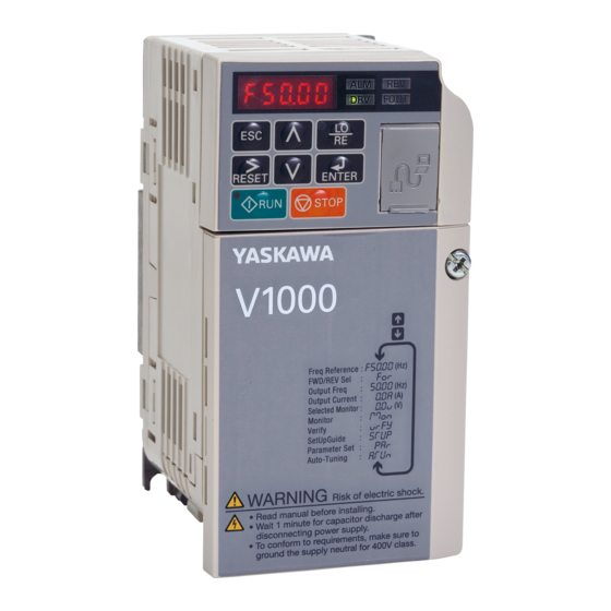
Page 30: Component Names
F – Terminal cover L – Cooling fan Refer to Drive Cooling Fans on page 254 Figure 1.2 Exploded View of IP20/Open-Chassis Type Components Three-Phase AC200 V CIMR-V 2A0006B YASKAWA ELECTRIC TOEP C710606 09B YASKAWA AC Drive V1000 Installation & Start-Up Manual... - Page 31 G – Front cover screw Figure 1.3 Exploded view of IP20/Open-Chassis Type Components Three-Phase AC200 V CIMR-V 2A0012B Note: CIMR-V BA0018B is supplied with two built-in cooling fans. YASKAWA ELECTRIC TOEP C710606 09B YASKAWA AC Drive V1000 Installation & Start-Up Manual...
-
Page 32: Ip20/Nema Type 1 Enclosure
Refer to Drive Cooling Fans on page 254 H – Bottom front cover Figure 1.4 Exploded View of IP20/NEMA Type 1 Components Three-phase AC200 V CIMR-V 2A00062F YASKAWA ELECTRIC TOEP C710606 09B YASKAWA AC Drive V1000 Installation & Start-Up Manual... - Page 33 Refer to Drive Cooling Fans on page 254 Figure 1.5 Exploded view of IP20/NEMA Type 1 Components Three-phase AC200 V CIMR-V 2A0012F Note: CIMR-V BA0018F is supplied with two built-in cooling fans. YASKAWA ELECTRIC TOEP C710606 09B YASKAWA AC Drive V1000 Installation & Start-Up Manual...
- Page 34 Refer to Using the Digital LED Operator on page 91 F – Front cover screws L – Case Figure 1.6 Exploded view of IP20/NEMA Type 1 Components Three-phase AC400 V CIMR-V 4A0018F YASKAWA ELECTRIC TOEP C710606 09B YASKAWA AC Drive V1000 Installation & Start-Up Manual...
-
Page 35: Front Views
Refer to MEMOBUS/Modbus page 71 Termination on page 82 E – Main circuit terminal Refer to Main Circuit Wiring on page 65 Figure 1.7 Front Views of Drives YASKAWA ELECTRIC TOEP C710606 09B YASKAWA AC Drive V1000 Installation & Start-Up Manual... - Page 36 1.4 Component Names YASKAWA ELECTRIC TOEP C710606 09B YASKAWA AC Drive V1000 Installation & Start-Up Manual...
-
Page 37: Mechanical Installation
2.1 SECTION SAFETY ....... 38 2.2 MECHANICAL INSTALLATION..... 41 YASKAWA ELECTRIC TOEP C710606 09B YASKAWA AC Drive V1000 Installation & Start-Up Manual... - Page 38 It may be difficult to perform maintenance on the cooling fans of drives installed in a vertical row inside an enclosure. Ensure adequate spacing at the top of the drive to perform cooling fan replacement when required. YASKAWA ELECTRIC TOEP C710606 09B YASKAWA AC Drive V1000 Installation & Start-Up Manual...
- Page 39 The motor may require more acceleration torque with drive operation than with a commercial power supply. Set a proper V/f pattern by checking the load torque characteristics of the machine to be used with the motor. YASKAWA ELECTRIC TOEP C710606 09B YASKAWA AC Drive V1000 Installation & Start-Up Manual...
- Page 40 The power transmission mechanism will make noise and experience problems with service life and durability if the motor is operated at a speed higher than 60 Hz. YASKAWA ELECTRIC TOEP C710606 09B YASKAWA AC Drive V1000 Installation & Start-Up Manual...
- Page 41 Remove the temporary cover before start-up, as the cover will reduce ventilation and cause the drive to overheat. YASKAWA ELECTRIC TOEP C710606 09B YASKAWA AC Drive V1000 Installation & Start-Up Manual...
-
Page 42: Installation Orientation And Spacing
D – Figure 2.2 Correct Installation Spacing Note: IP20/NEMA Type 1 and IP20/Open-Chassis models require the same amount of space above and below the drive for installation. YASKAWA ELECTRIC TOEP C710606 09B YASKAWA AC Drive V1000 Installation & Start-Up Manual... - Page 43 NOTICE: When drives with IP20/NEMA Type 1 enclosure are mounted side by side, the top covers of all units must be removed as shown in the figure below. Figure 2.4 Figure 2.4 IP20/NEMA 1 Side-by-Side Mounting in Enclosure YASKAWA ELECTRIC TOEP C710606 09B YASKAWA AC Drive V1000 Installation & Start-Up Manual...
-
Page 44: Removing And Attaching The Protective Covers
4 0031F 2 0069F 4 0038F Note: For information on the amount of heat generated by the drive and appropriate cooling methods, refer to Specifications on page 289. YASKAWA ELECTRIC TOEP C710606 09B YASKAWA AC Drive V1000 Installation & Start-Up Manual... - Page 45 Dimensions (mm) Drive Model Voltage Class Weight CIMR-V (kg) BA0001B Single-Phase BA0002B 200 V Class BA0003B 38.5 2A0001B 2A0002B Three-Phase 200 V Class 2A0004B 38.5 2A0006B 58.5 YASKAWA ELECTRIC TOEP C710606 09B YASKAWA AC Drive V1000 Installation & Start-Up Manual...
- Page 46 200 V Class BA0012B BA0018B 2A0008B Three-Phase 2A0010B 200 V Class 2A0012B 137.5 2A0018B 2A0020B 4A0001B 4A0002B 4A0004B 137.5 Three-Phase 4A0005B 400 V Class 4A0007B 4A0009B 4A0011B YASKAWA ELECTRIC TOEP C710606 09B YASKAWA AC Drive V1000 Installation & Start-Up Manual...
- Page 47 6.5 149.5 20 2A0002F 68 129.5 76 6.5 149.5 20 Three-Phase 200 V Class 2A0004F 68 129.5 108 39 149.5 20 2A0006F 68 129.5 128 59 149.5 20 YASKAWA ELECTRIC TOEP C710606 09B YASKAWA AC Drive V1000 Installation & Start-Up Manual...
- Page 48 108 129.5 154 58 149.5 20 400 V Class 4A0007F 108 129.5 154 58 149.5 20 4A0009F 108 129.5 154 58 149.5 20 4A0011F 140 133 143 YASKAWA ELECTRIC TOEP C710606 09B YASKAWA AC Drive V1000 Installation & Start-Up Manual...
- Page 49 122 248 140 234 140 1.5 M5 Three-Phase 400 V Class 4A0031B 160 284 180 270 143 1.5 M5 4A0038B 160 284 180 270 163 1.5 M5 YASKAWA ELECTRIC TOEP C710606 09B YASKAWA AC Drive V1000 Installation & Start-Up Manual...
- Page 50 2.2 Mechanical Installation YASKAWA ELECTRIC TOEP C710606 09B YASKAWA AC Drive V1000 Installation & Start-Up Manual...
-
Page 51: Electrical Installation
3.12 WIRING CHECKLIST ......85 YASKAWA ELECTRIC TOEP C710606 09B YASKAWA AC Drive V1000 Installation & Start-Up Manual... - Page 52 Do not remove covers or touch circuit boards while the power is on. Failure to comply could result in death or serious injury. YASKAWA ELECTRIC TOEP C710606 09B YASKAWA AC Drive V1000 Installation & Start-Up Manual...
- Page 53 Failure to comply could result in death or serious injury by fire. Verify that the rated voltage of the drive matches the voltage of the incoming power supply before applying power. YASKAWA ELECTRIC TOEP C710606 09B YASKAWA AC Drive V1000 Installation & Start-Up Manual...
- Page 54 Failure to comply could result in damage to the drive and will void warranty. Yaskawa is not responsible for any modification of the product made by the user. This product must not be modified. YASKAWA ELECTRIC TOEP C710606 09B YASKAWA AC Drive V1000 Installation & Start-Up Manual...
-
Page 55: Standard Connection Diagram
10 mA, connect it to a photocoupler output (P1, P2, PC). Improper application of peripheral devices could result in damage to the photocoupler output of the drive. YASKAWA ELECTRIC TOEP C710606 09B YASKAWA AC Drive V1000 Installation & Start-Up Manual... - Page 56 Safe Disable Input Jumper MEMOBUS/ Modbus comm. RS-485/422 Cable shield ground shielded line twisted-pair shielded line control terminal main circuit terminal Figure 3.1 Drive Standard Connection Diagram YASKAWA ELECTRIC TOEP C710606 09B YASKAWA AC Drive V1000 Installation & Start-Up Manual...
- Page 57 Stop relay (N.C.) Run command (run on momentary close) Stop command (stop on momentary open) Foward/reverse command (multi-function input: H1-05 = 0) Sequence input common Figure 3.2 3-Wire Sequence YASKAWA ELECTRIC TOEP C710606 09B YASKAWA AC Drive V1000 Installation & Start-Up Manual...
-
Page 58: Main Circuit Connection Diagram
Resistor Unit (option) (option) Jumper B1 B2 Drive R/L1 U/T1 S/L2 V/T2 Motor T/L3 W/T3 Three phase 200 Vac (400 Vac) Figure 3.4 Connecting Main Circuit Terminals YASKAWA ELECTRIC TOEP C710606 09B YASKAWA AC Drive V1000 Installation & Start-Up Manual... -
Page 59: Terminal Block Configuration
0002, 0003 CIMR-V 2A0008, 0010, 0012, 0018, 0020 CIMR-V 2A0001, 0002, 0004, 0006 CIMR-V 4A0001, 0002, 0004, 0005, 0007, 0009, 0011 Figure 3.5 Main Circuit Terminal Block Configurations YASKAWA ELECTRIC TOEP C710606 09B YASKAWA AC Drive V1000 Installation & Start-Up Manual... - Page 60 Figure 3.6 Model CIMR-V BA0018 Figure 3.6 Main Circuit Terminal Block Configurations Figure 3.7 Models CIMR-V 2A0030, 0040 CIMR-V 4A0018, 0023 Figure 3.7 Main Circuit Terminal Block Configurations YASKAWA ELECTRIC TOEP C710606 09B YASKAWA AC Drive V1000 Installation & Start-Up Manual...
- Page 61 Figure 3.8 Models CIMR-V 2A0056 CIMR-V 4A0031, 0038 Figure 3.8 Main Circuit Terminal Block Configurations Figure 3.9 Model CIMR-V 2A0069 Figure 3.9 Main Circuit Terminal Block Configurations YASKAWA ELECTRIC TOEP C710606 09B YASKAWA AC Drive V1000 Installation & Start-Up Manual...
-
Page 62: Protective Covers
Properly connect all wiring and route power wiring away from control signal wiring. Reattach all protective covers when wiring is complete. Apply only a small amount of pressure to lock the cover back into place. YASKAWA ELECTRIC TOEP C710606 09B YASKAWA AC Drive V1000 Installation & Start-Up Manual... -
Page 63: Ip20/Nema Type 1
3.14, A). Figure 3.14 Figure 3.14 Remove the Terminal Cover on an IP20/NEMA Type 1 Drive Loosen two screws attaching the conduit bracket (Figure 3.15, A) to remove. YASKAWA ELECTRIC TOEP C710606 09B YASKAWA AC Drive V1000 Installation & Start-Up Manual... - Page 64 A – Pass power wiring and control signal wiring through different exit holes at the bottom of the drive. Figure 3.16 Reattach the Protective Covers and Conduit Bracket on an IP20/NEMA Type 1 Drive YASKAWA ELECTRIC TOEP C710606 09B YASKAWA AC Drive V1000 Installation & Start-Up Manual...
-
Page 65: Main Circuit Wiring
Ensure the wire gauge is suitable for the terminal block. Use the following formula to calculate the amount of voltage drop: • Line drop voltage (V) = 3 x wire resistance (Ω/km) x wire length (m) x current (A) x10 YASKAWA ELECTRIC TOEP C710606 09B YASKAWA AC Drive V1000 Installation & Start-Up Manual... - Page 66 R/L1, S/L2, T/L3, U/T1, V/T2, 1.2 to 1.5 2.0 to 5.5 0020 Note: 1. (10.6 to 13.3) (14 to 10) (10) W/T3, –, +1, +2, B1, B2, YASKAWA ELECTRIC TOEP C710606 09B YASKAWA AC Drive V1000 Installation & Start-Up Manual...
- Page 67 W/T3, –, +1, +2, B1, B2 (10.6 to 13.3) (14 to 10) (14) 0009 1.2 to 1.5 2.0 to 5.5 Note: 1. (10.6 to 13.3) (14 to 10) (12) YASKAWA ELECTRIC TOEP C710606 09B YASKAWA AC Drive V1000 Installation & Start-Up Manual...
-
Page 68: Main Circuit Terminal Power Supply And Motor Wiring
NOTICE: Do not connect the AC power line to the output motor terminals of the drive. Failure to comply could result in death or serious injury by fire as a result of drive damage from line voltage application to YASKAWA ELECTRIC TOEP C710606 09B YASKAWA AC Drive V1000 Installation & Start-Up Manual... - Page 69 NOTICE: When using more than one drive, ground multiple drives according to instructions. Improper equipment grounding could result in abnormal operation of drive or equipment. Refer to Figure 3.17 when using multiple drives. Do not loop the ground wire. YASKAWA ELECTRIC TOEP C710606 09B YASKAWA AC Drive V1000 Installation & Start-Up Manual...
- Page 70 Improper wiring connections could cause the braking resistor to overheat and cause death or serious injury by fire. Failure to comply may result in damage to the braking circuit or drive. YASKAWA ELECTRIC TOEP C710606 09B YASKAWA AC Drive V1000 Installation & Start-Up Manual...
-
Page 71: Control Circuit Wiring
* 3. Minimum load: 5 Vdc, 10 mA (reference value). NOTICE: Do not solder the ends of wire connections to the drive. Soldered wire connections can loosen YASKAWA ELECTRIC TOEP C710606 09B YASKAWA AC Drive V1000 Installation & Start-Up Manual... -
Page 72: Control Circuit Terminal Block Functions
+24 Vdc (max 10 mA allowed) Safety Open: Coast to stop safety input Input Safety input command Closed: Normal operation Note: Disconnect wire jumper between HC and H1 when using safety input. YASKAWA ELECTRIC TOEP C710606 09B YASKAWA AC Drive V1000 Installation & Start-Up Manual... - Page 73 Connect a suppression diode as shown in Figure 3.19 when driving a reactive load such as a relay coil. Ensure the diode rating is greater than the circuit voltage. YASKAWA ELECTRIC TOEP C710606 09B YASKAWA AC Drive V1000 Installation & Start-Up Manual...
-
Page 74: Removable Terminal Block Configuration
Select the appropriate wires and crimp terminals from Table 3.10. Crimp a ferrule to signal wiring to improve wiring simplicity and reliability. Refer to Ferrule Terminal Types and Sizes on page YASKAWA ELECTRIC TOEP C710606 09B YASKAWA AC Drive V1000 Installation & Start-Up Manual... - Page 75 (mm) d2 (mm) Manufacturer 0.25 (24) AI 0.25-6YE 10.5 0.34 (22) AI 0.34-6TQ 10.5 0.5 (20) AI 0.5-6WH PHOENIX CONTACT 0.75 (18) A1 0.75-6GY AI 1-6RD YASKAWA ELECTRIC TOEP C710606 09B YASKAWA AC Drive V1000 Installation & Start-Up Manual...
-
Page 76: Wiring Procedure
Blade width of 2.5 mm or less Strip length 5.5 mm. C – Single wire or stranded wire Figure 3.22 Terminal Board Wiring Guide YASKAWA ELECTRIC TOEP C710606 09B YASKAWA AC Drive V1000 Installation & Start-Up Manual... - Page 77 (maximum 32 kHz) D – (+V) Frequency setting power source +10.5 Vdc maximum 20 mA Figure 3.24 Wiring the Frequency Reference to the Control Circuit Terminals (External Reference) YASKAWA ELECTRIC TOEP C710606 09B YASKAWA AC Drive V1000 Installation & Start-Up Manual...
-
Page 78: I/O Connections
When controlling the digital inputs by NPN transistors (0 V common / sinking mode), set the DIP switch S3 to SINK and use the internal 24 V power supply. YASKAWA ELECTRIC TOEP C710606 09B YASKAWA AC Drive V1000 Installation & Start-Up Manual... - Page 79 Fault rest power supply +24 V Multi-step speed 1 Multi-step speed 2 Jog frequency SINK +24V SOURCE Figure 3.27 Source Mode: Sequence from PNP Transistor (+24 V Common) YASKAWA ELECTRIC TOEP C710606 09B YASKAWA AC Drive V1000 Installation & Start-Up Manual...
-
Page 80: Main Frequency Reference
(voltage input) (voltage input) Main speed 0 to 20 mA input Main speed frequency reference frequency reference (current input) (current input) Frequency reference Frequency reference common common YASKAWA ELECTRIC TOEP C710606 09B YASKAWA AC Drive V1000 Installation & Start-Up Manual... - Page 81 1: 0 to +10 V, bipolar input (negative frequency 0 to 3 terminal A2 signal level selection reference changes the direction) 2: 4 to 20 mA 3: 0 to 20 mA YASKAWA ELECTRIC TOEP C710606 09B YASKAWA AC Drive V1000 Installation & Start-Up Manual...
-
Page 82: Memobus/Modbus Termination
Internal terminal resistance OFF (no terminal resistance); default setting Figure 3.29 DIP Switch S2 Figure 3.29 DIP Switch S2 Note: Refer to the MEMOBUS/Modbus communications manual for details on MEMOBUS/Modbus. YASKAWA ELECTRIC TOEP C710606 09B YASKAWA AC Drive V1000 Installation & Start-Up Manual... -
Page 83: Braking Resistor
Remove drive front cover. Use a voltmeter to verify that voltage is disconnected from incoming power terminals and that the DC bus no longer holds a charge. YASKAWA ELECTRIC TOEP C710606 09B YASKAWA AC Drive V1000 Installation & Start-Up Manual... - Page 84 <2> This setting cannot be used in OLV control for PM motor. Operation Check ■ Operate the system and verify the required deceleration rate is obtained during dynamic braking or stopping. YASKAWA ELECTRIC TOEP C710606 09B YASKAWA AC Drive V1000 Installation & Start-Up Manual...
-
Page 85: Wiring Checklist
(C6-02) accordingly. Properly ground the drive. Review page 69. Tightly fasten all terminal screws (control circuit terminals, grounding terminals). Refer to Table 3.2, Table 3.3 Table 3.4. YASKAWA ELECTRIC TOEP C710606 09B YASKAWA AC Drive V1000 Installation & Start-Up Manual... - Page 86 Properly separate control circuit wiring and main circuit wiring. Analog signal line wiring should not exceed 10 m. All other wiring should be less than 50 m. YASKAWA ELECTRIC TOEP C710606 09B YASKAWA AC Drive V1000 Installation & Start-Up Manual...
- Page 87 4.8 TEST RUN CHECKLIST......171 YASKAWA ELECTRIC TOEP C710606 09B YASKAWA AC Drive V1000 Installation & Start-Up Manual...
- Page 88 50 Vdc. To prevent electric shock, wait at least five minutes after all indicators are off and measure the DC bus voltage level to confirm safe level. YASKAWA ELECTRIC TOEP C710606 09B YASKAWA AC Drive V1000 Installation & Start-Up Manual...
- Page 89 Do not use improper combustible materials. Failure to comply could result in death or serious injury by fire. Attach the drive to metal or other noncombustible material. YASKAWA ELECTRIC TOEP C710606 09B YASKAWA AC Drive V1000 Installation & Start-Up Manual...
- Page 90 Failure to comply could result in damage to the drive and will void warranty. Yaskawa is not responsible for any modification of the product made by the user. This product must not be modified. Check all the wiring to ensure that all connections are correct after installing the drive and connecting any other devices.
-
Page 91: Using The Digital Led Operator
Read manual before installing. Wait 1 minute for capacitor discharge after disconnecting power supply. To conform to requirements, make sure to ground the supply neutral for 400V class. YASKAWA ELECTRIC TOEP C710606 09B YASKAWA AC Drive V1000 Installation & Start-Up Manual... - Page 92 Key Function Selection) to “0” (disabled) to disable LOCAL/ REMOTE key. RUN Light Lit while the drive is operating the motor. LO/RE Light Lit while the operator (LOCAL) is selected to run the drive. YASKAWA ELECTRIC TOEP C710606 09B YASKAWA AC Drive V1000 Installation & Start-Up Manual...
-
Page 93: Digital Text Display
Flashing Table 4.2 Digital Text Display Text Text Text Text <1> <1> none none <1> Displayed in two digits. YASKAWA ELECTRIC TOEP C710606 09B YASKAWA AC Drive V1000 Installation & Start-Up Manual... -
Page 94: Led Screen Displays
As shown <1> For the difference between “flashing” and “flashing in short intervals” of the RUN LED, refer to Figure 4.2, RUN LED and Drive Operation. YASKAWA ELECTRIC TOEP C710606 09B YASKAWA AC Drive V1000 Installation & Start-Up Manual... - Page 95 Figure 4.1 RUN LED Status and Meaning Figure 4.2 drive output frequency during stop STOP STOP 6 Hz 0 Hz frequency setting RUN LED Flashing Figure 4.2 RUN LED and Drive Operation YASKAWA ELECTRIC TOEP C710606 09B YASKAWA AC Drive V1000 Installation & Start-Up Manual...
-
Page 96: Menu Structure For Digital Led Operator
Monitor Display Verify Menu Set Up Mode Parameter Setting Mode Auto-Tuning Figure 4.3 Digital LED Operator Screen Structure * “rEu” can be selected while LOCAL is set. YASKAWA ELECTRIC TOEP C710606 09B YASKAWA AC Drive V1000 Installation & Start-Up Manual... -
Page 97: The Drive And Programming Modes
Drive Mode Functions (Motor operation and monitoring) Output Current Display Output Voltage Reference Monitor Display Verify Function Setup Group Parameters Programming Mode Functions (Changing parameters) All Parameters Auto-Tuning YASKAWA ELECTRIC TOEP C710606 09B YASKAWA AC Drive V1000 Installation & Start-Up Manual... -
Page 98: Navigating The Drive And Programming Modes
The LED is lit when LOCAL is selected Drive Mode Output Frequency Display Monitors the frequency output by the drive. Output Current Display Monitors the output current of the drive. YASKAWA ELECTRIC TOEP C710606 09B YASKAWA AC Drive V1000 Installation & Start-Up Manual... - Page 99 Allows the user to access and edit all parameter settings. Refer to Parameter List on page 305. Auto-Tuning Motor parameters are calculated and set automatically. Refer to Auto-Tuning on page 153. YASKAWA ELECTRIC TOEP C710606 09B YASKAWA AC Drive V1000 Installation & Start-Up Manual...
- Page 100 By setting o2-05 (Frequency Reference Setting Method Selection) to 1 (Enabled), the drive will accept the frequency reference while it is being adjusted on the digital operator. YASKAWA ELECTRIC TOEP C710606 09B YASKAWA AC Drive V1000 Installation & Start-Up Manual...
- Page 101 *2 Move to the right to change parameter settings. Scroll down to view and check settings in the Setup Mode *3 To return to the Top Menu, press . To view or edit other parameters, press Figure 4.5 Setup Group Example YASKAWA ELECTRIC TOEP C710606 09B YASKAWA AC Drive V1000 Installation & Start-Up Manual...
-
Page 102: Changing Parameter Settings Or Values
The Verify menu also allows users to access and re-edit edited parameters. Note: The Verify Menu will not display parameters from the A1 group (except for A1-02) even if those parameters have been changed from default settings. YASKAWA ELECTRIC TOEP C710606 09B YASKAWA AC Drive V1000 Installation & Start-Up Manual... -
Page 103: Switching Between Local And Remote
2. The drive will not allow the user to switch between LOCAL and REMOTE during run. Using the LO/RE Key on the LED Operator ■ Step Display/Result ⇒ Turn on the power to the drive. The initial display appears. YASKAWA ELECTRIC TOEP C710606 09B YASKAWA AC Drive V1000 Installation & Start-Up Manual... -
Page 104: Parameters Available In The Setup Group
A1-02 Control Method Selection E1-01 Input Voltage Reference b1-01 Frequency Reference Selection 1 E1-03 V/f Pattern Selection b1-02 Run Command Selection 1 E1-04 Maximum Output Frequency (FMAX) YASKAWA ELECTRIC TOEP C710606 09B YASKAWA AC Drive V1000 Installation & Start-Up Manual... - Page 105 Frequency Reference 3 H4-02 Terminal FM Gain Setting d1-04 Frequency Reference 4 L1-01 Motor Protection Function Selection d1-17 Jog Frequency Reference L3-04 Stall Prevention Selection during Deceleration YASKAWA ELECTRIC TOEP C710606 09B YASKAWA AC Drive V1000 Installation & Start-Up Manual...
-
Page 106: Start-Up Flowcharts
4.6, Flowchart A, describes basic start-up sequence for the drive and motor system. This sequence varies slightly depending on application. Use drive default parameter settings in simple applications that do not require high precision. YASKAWA ELECTRIC TOEP C710606 09B YASKAWA AC Drive V1000 Installation & Start-Up Manual... - Page 107 Fine tune parameters. Adjust application settings (PID, ...) if necessary Check the machine operation and verify parameter settings. Drive is ready to run the application Figure 4.6 Basic Start-Up and Motor Tuning YASKAWA ELECTRIC TOEP C710606 09B YASKAWA AC Drive V1000 Installation & Start-Up Manual...
-
Page 108: Speed Search Using V/F Mode
(T1-01 = 3) Perform Stationary Auto-Tuning for terminal resistance (T1-01 = 2) Return to Flowchart Figure 4.7 Simple Motor Set-Up with Energy Savings or Speed Search Using V/f Mode YASKAWA ELECTRIC TOEP C710606 09B YASKAWA AC Drive V1000 Installation & Start-Up Manual... -
Page 109: Open Loop Vector Motor Control
50 m? Perform Stationary Auto-Tuning for terminal resistance (T1-01 = 2) Return to Flowchart Figure 4.8 Flowchart A2: High Performance Operation Using Open Loop Vector Motor Control YASKAWA ELECTRIC TOEP C710606 09B YASKAWA AC Drive V1000 Installation & Start-Up Manual... -
Page 110: Subchart A3: Operation With Permanent Magnet Motors
Enter “FFFF” to parameter E5- Set the motor code to Enter the motor data into parameter E5-01 parameters E5-02 to E5-24 Return to Flowchart Figure 4.9 Operation with Permanent Magnet Motorsl YASKAWA ELECTRIC TOEP C710606 09B YASKAWA AC Drive V1000 Installation & Start-Up Manual... -
Page 111: Application Presets
3: Exhaust fan A1-06 Applicaton Presets 4: HVAC fan <1> 5: Air compressor 6: Hoist 7: Crane (hoist, traverse) <1> All general-purpose parameters are accessible when A1-06 = 0. YASKAWA ELECTRIC TOEP C710606 09B YASKAWA AC Drive V1000 Installation & Start-Up Manual... - Page 112 A1-03 Initialize Parameters 2220: 2-Wire Initialization 3330: 3-Wire Initialization 4440: DriveWorksEZ Initialization 5550: OPE04 Error Reset A2-02 User Parameters, b1-01 to o2-08 <1> 2 to 32 A2-32 YASKAWA ELECTRIC TOEP C710606 09B YASKAWA AC Drive V1000 Installation & Start-Up Manual...
- Page 113 S5 Function Selection Multi-Function Digital Input Terminal C1-01 Acceleration Time 1 H1-06 S6 Function Selection Multi-Function Digital Input Terminal C1-02 Deceleration Time 1 H1-07 S7 Function Selection YASKAWA ELECTRIC TOEP C710606 09B YASKAWA AC Drive V1000 Installation & Start-Up Manual...
- Page 114 Frequency Reference Selection E1-07 Mid Output Frequency (FB) b1-02 Run Command Selection E1-08 Mid Output Frequency Voltage (VC) b1-04 Reverse Operation Selection E2-01 Motor Rated Current YASKAWA ELECTRIC TOEP C710606 09B YASKAWA AC Drive V1000 Installation & Start-Up Manual...
- Page 115 C6-02 Carrier Frequency Selection L2-01 Selection Overheat Pre-Alarm Operation d2-01 Frequency Reference Upper Limit L8-03 Selection d2-02 Frequency Reference Lower Limit o4-12 kWH Monitor Initial Value Selection YASKAWA ELECTRIC TOEP C710606 09B YASKAWA AC Drive V1000 Installation & Start-Up Manual...
- Page 116 Terminals P1 Function Selection (open-collector) 37: During frequency output H2-03 Terminals P2 Function Selection (open-collector) 5: Frequency Detection 2 (FOUT) L2-03 Momentary Power Loss Minimum Baseblock Time 0.3 s YASKAWA ELECTRIC TOEP C710606 09B YASKAWA AC Drive V1000 Installation & Start-Up Manual...
- Page 117 0: Operator C1-01 Acceleration Time 1 3.0 s C1-02 Deceleration Time 1 3.0 s C6-01 Duty Cycle 0: Heavy Duty C6-02 Carrier Frequency Selection 2: 5 kHz YASKAWA ELECTRIC TOEP C710606 09B YASKAWA AC Drive V1000 Installation & Start-Up Manual...
- Page 118 (i.e., L4-07 = 1) then the brake would be improperly released. To activate and release the brake using the multi-function output terminals P2-PC, program the drive as shown in the table below: YASKAWA ELECTRIC TOEP C710606 09B YASKAWA AC Drive V1000 Installation & Start-Up Manual...
- Page 119 Circuit DOWN DOWN Reverse Frequency Detect 2 High speed Multi-step speed 2) ON Brake energized Low speed DC 30V 1 A Figure 4.10 Holding Brake Circuit Design YASKAWA ELECTRIC TOEP C710606 09B YASKAWA AC Drive V1000 Installation & Start-Up Manual...
-
Page 120: User Parameters: A2-01 To A2-32
◆ User Parameter Automatic Selection: A2-33 A2-33 determines whether parameters that have been edited are saved to the User Parameters (A2-17 to A2-32) for quick, easy access. YASKAWA ELECTRIC TOEP C710606 09B YASKAWA AC Drive V1000 Installation & Start-Up Manual... - Page 121 By setting A2-33 to 1, all parameters that were recently edited will be saved to A2-17 through A2-32. A total of 16 parameters are saved in order, with the most recently edited parameter set to A2-17. YASKAWA ELECTRIC TOEP C710606 09B YASKAWA AC Drive V1000 Installation & Start-Up Manual...
-
Page 122: Basic Drive Setup Adjustments
After saving all parameter setting changes, parameter o2-03 automatically returns to 0. Refer to Verifying Parameter Settings and Backing Up Changes on page 163. 2220: 2-Wire Initialization Returns all parameters to factory default values for 2-wire control. YASKAWA ELECTRIC TOEP C710606 09B YASKAWA AC Drive V1000 Installation & Start-Up Manual... -
Page 123: Application Presets: A1-06
3: Exhaust fan A1-06 Appilcaton Presets 4: HVAC fan <1> 5: Air compressor 6: Hoist 7: Crane (hoist, traverse) <1> All general-purpose parameters are accessible when A1-06 = 0. YASKAWA ELECTRIC TOEP C710606 09B YASKAWA AC Drive V1000 Installation & Start-Up Manual... -
Page 124: Dwez Function Selection: A1-07
Control Circuit Terminal A1 (Voltage Input): When entering the main frequency reference with a voltage signal, use the voltage input set up in control circuit terminal A1. YASKAWA ELECTRIC TOEP C710606 09B YASKAWA AC Drive V1000 Installation & Start-Up Manual... - Page 125 3. Set input signal type of terminal A2 using dip switch S1 and parameter H3-09. 4. Set the function of analog input A2 to Auxiliary frequency (H3-10 = “3”). YASKAWA ELECTRIC TOEP C710606 09B YASKAWA AC Drive V1000 Installation & Start-Up Manual...
- Page 126 Pulse Train Input Specifications Response Frequency 0.5 to 32 kHz Duty Cycle 30 to 70% High Level Voltage 3.5 to 13.2 V Low Level Voltage 0.0 to 0.8 V YASKAWA ELECTRIC TOEP C710606 09B YASKAWA AC Drive V1000 Installation & Start-Up Manual...
-
Page 127: Run Command Input Selection: B1-02
⇒ Note: Refer to Drive Mode Details on page 100 for instructions on how to set the frequency reference. ⇒ Press the key to start the motor. YASKAWA ELECTRIC TOEP C710606 09B YASKAWA AC Drive V1000 Installation & Start-Up Manual... - Page 128 When H1-05 (Multi-Function Digital Input Terminal S5 Function Selection) = 0, the functions of terminals S1 and S2 are set to 3-wire sequence, and the multi-function input terminal becomes forward/reverse run command terminal. YASKAWA ELECTRIC TOEP C710606 09B YASKAWA AC Drive V1000 Installation & Start-Up Manual...
-
Page 129: Stopping Method Selection: B1-03
When the output frequency falls below the DC Injection braking start frequency (b2-01) during deceleration, the DC Injection braking current (b2-02) will be activated for the specified DC Injection time at stop (b2-04). YASKAWA ELECTRIC TOEP C710606 09B YASKAWA AC Drive V1000 Installation & Start-Up Manual... - Page 130 DC Injection Braking stops a coasting motor without without regenerative operation. When the run command is removed, the drive will baseblock (turn off its output) for the minimum YASKAWA ELECTRIC TOEP C710606 09B YASKAWA AC Drive V1000 Installation & Start-Up Manual...
- Page 131 “t” has passed. Time “t” is determined by the output frequency at the moment the stop command was entered and the deceleration time set to the drive according to Figure 4.20. YASKAWA ELECTRIC TOEP C710606 09B YASKAWA AC Drive V1000 Installation & Start-Up Manual...
-
Page 132: Acceleration/Deceleration: C1-01 To C1-11
C1-09 when using the Fast-stop feature. Accel/Decel Time Setting Units ■ Set the units for the acceleration and deceleration times using parameter C1-10 (default = 1). YASKAWA ELECTRIC TOEP C710606 09B YASKAWA AC Drive V1000 Installation & Start-Up Manual... - Page 133 C1-11, drive uses Accel/Decel Time 1 (C1-01, -02) When the output frequency < C1-11, drive uses Accel/Decel Time 2 (C1-07, -08) Figure 4.21 Accel/Decel Time Switching Frequency YASKAWA ELECTRIC TOEP C710606 09B YASKAWA AC Drive V1000 Installation & Start-Up Manual...
-
Page 134: C6-01 And C6-02
ND. Refer to Specifications on page 289 for details about the rated current. HD and ND Mode Selections Mode HD Rating ND Duty Rating C6-01 YASKAWA ELECTRIC TOEP C710606 09B YASKAWA AC Drive V1000 Installation & Start-Up Manual... - Page 135 Note: Settings 7 through A for parameter C6-02 use a Swing PWM equivalent to a 2 kHz audible noise. This function turns the motor noise into a less obtrusive white noise. Note: The upper limit for the carrier frequency is determined by drive capacity. YASKAWA ELECTRIC TOEP C710606 09B YASKAWA AC Drive V1000 Installation & Start-Up Manual...
- Page 136 Note: For Open Loop Vector Mode, A1-02 = 2 and OLV for PM the carrier frequency is fixed to a value set by C6-02 or C6-03 if C6-02 is set to F (programmable). YASKAWA ELECTRIC TOEP C710606 09B YASKAWA AC Drive V1000 Installation & Start-Up Manual...
- Page 137 2.2 kW/ 1.5W 1.5W 1.5W 12.0 12.0 B 0012 2 0012 4 0007 3.0 kW/ 11.0 3.0 kW/ 11.0 3.0 kW/ 2.2 kW 2.2 kW 2.2 kW YASKAWA ELECTRIC TOEP C710606 09B YASKAWA AC Drive V1000 Installation & Start-Up Manual...
-
Page 138: Drive Input Voltage Setting: E1-01
≥ 400V 820 V 788 V 380 V 480 V 740 V 400 V Class setting < 400V 740 V 708 V 350 V 440 V 660 V YASKAWA ELECTRIC TOEP C710606 09B YASKAWA AC Drive V1000 Installation & Start-Up Manual... -
Page 139: V/F Pattern Selection: E1-03
There are two types of V/f patterns: a method to select one of the 15 presets (set value: 0 to E) and a method to select arbitraty V/f pattern (set value: F). Refer to Table 4.20. YASKAWA ELECTRIC TOEP C710606 09B YASKAWA AC Drive V1000 Installation & Start-Up Manual... - Page 140 V/f Pattern Characteristics ■ These graphs apply to 200 V class drives; double the values for 400 V class drives. • Constant Torque Characteristics, Settings 0 through 3 YASKAWA ELECTRIC TOEP C710606 09B YASKAWA AC Drive V1000 Installation & Start-Up Manual...
- Page 141 Setting = 4 50 Hz Setting = 5 50 Hz Setting = 6 60 Hz Setting = 7 60 Hz Frequency (Hz) Frequency (Hz) Frequency (Hz) Frequency (Hz) YASKAWA ELECTRIC TOEP C710606 09B YASKAWA AC Drive V1000 Installation & Start-Up Manual...
- Page 142 Setting Motor Parameters Manually ■ The following table provides instructions on how to set motor parameters. Refer to the motor data sheet for the correct motor data. YASKAWA ELECTRIC TOEP C710606 09B YASKAWA AC Drive V1000 Installation & Start-Up Manual...
- Page 143 <1> <1> Parameters E2-07 through E2-08 and E2-12 may be difficult to set manually. If Auto-Tuning is not possible, simply leave these settings at the default values. YASKAWA ELECTRIC TOEP C710606 09B YASKAWA AC Drive V1000 Installation & Start-Up Manual...
-
Page 144: Digital Outputs H2-01 To H2-03
LED operator. Analog outputs corresponding to these monitors can be obtained on analog output terminal AM or Fm when programmed with parameter group H4. Some Group U monitors are not available as analog outputs. YASKAWA ELECTRIC TOEP C710606 09B YASKAWA AC Drive V1000 Installation & Start-Up Manual... - Page 145 H4-01. ⇒ Press to set the output current (103). ⇒ Save the setting by pressing ⇒ The display automatically returns to the parameter setting menu. YASKAWA ELECTRIC TOEP C710606 09B YASKAWA AC Drive V1000 Installation & Start-Up Manual...
-
Page 146: Motor Protection: L1-01 And L1-02
When multiple motors are used with a single drive, separate overload devices are required to properly protect the individual motor branches. YASKAWA ELECTRIC TOEP C710606 09B YASKAWA AC Drive V1000 Installation & Start-Up Manual... - Page 147 2. These values are automatically set by performing Auto-Tuning. 3. The E4-01 setting is not needed if not using motor 2. Set the proper motor protection level to L1-01. YASKAWA ELECTRIC TOEP C710606 09B YASKAWA AC Drive V1000 Installation & Start-Up Manual...
- Page 148 Inverter Duty Motor designed to Continuous operation motor effectively self-cool at between 6 and 50/60 Hz. (1:10) speeds as low as 6 Hz. Continuous 0 1 10 (60Hz) YASKAWA ELECTRIC TOEP C710606 09B YASKAWA AC Drive V1000 Installation & Start-Up Manual...
- Page 149 Figure 4.27 illustrates motor protection operation time characteristics. Figure 4.27 Operation Time (minutes) Cold Start Hot Start Motor Current (%) E2-01 = 100% Figure 4.27 Motor Protection Operation YASKAWA ELECTRIC TOEP C710606 09B YASKAWA AC Drive V1000 Installation & Start-Up Manual...
-
Page 150: Drive Status Monitors: U1-01 To U6-19
U3-11 Recent Fault Cumulative Operation Time at 2nd U1-03 Output Current U3-12 Most Recent Fault Cumulative Operation Time at 3rd U1-04 Control Mode U3-13 Most Recent Fault YASKAWA ELECTRIC TOEP C710606 09B YASKAWA AC Drive V1000 Installation & Start-Up Manual... - Page 151 U2-11 Input Terminal Status at Previous Fault U5-03 PID Output U2-12 Output Terminal Status at Prev. Fault U5-04 PID Setpoint U2-13 Drive Operation Status at Pre. Fault U6-01 Torque Reference (Internal) YASKAWA ELECTRIC TOEP C710606 09B YASKAWA AC Drive V1000 Installation & Start-Up Manual...
- Page 152 U3-07 7th Most Recent Fault U6-20 Frequency Ref. Bias (Up/Down 2) U3-08 8th Most Recent Fault U6-21 Offset Frequency U3-09 9th Most Recent Fault Custom Monitors for DriveWorksEZ YASKAWA ELECTRIC TOEP C710606 09B YASKAWA AC Drive V1000 Installation & Start-Up Manual...
-
Page 153: Test Run
Causes, and Possible Solutions on page 187 for more information Fault and corrective action. are lit. Main circuit low voltage (ex) ◆ Auto-Tuning Auto-Tuning automatically sets and tunes parameters required for motor operation. YASKAWA ELECTRIC TOEP C710606 09B YASKAWA AC Drive V1000 Installation & Start-Up Manual... - Page 154 Auto-Tuning has been previously performed Open Loop Vector Control Line Resistance When motor capacity and drive capacity differ Only Note: Auto-Tuning cannot be performed on permanent magnet motors (IPM, SPM, etc.). YASKAWA ELECTRIC TOEP C710606 09B YASKAWA AC Drive V1000 Installation & Start-Up Manual...
- Page 155 OLV control is needed. Run the motor without the load. Connect the load and run the motor. Verify system operates as required. Auto-Tuning finished. Figure 4.28 YASKAWA ELECTRIC TOEP C710606 09B YASKAWA AC Drive V1000 Installation & Start-Up Manual...
- Page 156 • It is possible to perform Rotational Auto-Tuning with a connected load if the load is less than 30% of the rated load. • Ensure a motor-mounted brake is fully released. YASKAWA ELECTRIC TOEP C710606 09B YASKAWA AC Drive V1000 Installation & Start-Up Manual...
- Page 157 ⇒ Turn on the power to the drive. The initial display appears. ⇒ Press the key until the Auto-Tuning screen appears. ⇒ Press to begin setting parameters. YASKAWA ELECTRIC TOEP C710606 09B YASKAWA AC Drive V1000 Installation & Start-Up Manual...
- Page 158 “0.2.” Enter value based on motor ⇒ nameplate data. ⇒ Press to save the setting. ⇒ The display automatically returns to the screen shown in Step 1. YASKAWA ELECTRIC TOEP C710606 09B YASKAWA AC Drive V1000 Installation & Start-Up Manual...
- Page 159 Note: The first digit indicates which motor is undergoing Auto-Tuning (motor 1 or motor 2). The second digit indicates the type of Auto-Tuning being performed. ⇒ Auto-Tuning finishes in approximately one to two minutes. YASKAWA ELECTRIC TOEP C710606 09B YASKAWA AC Drive V1000 Installation & Start-Up Manual...
- Page 160 Sets the base speed of the motor in revolutions per minute r/min 0 to 1750. T1-07 Base (RPM). Enter the motor base speed for extended speed range 24000 r/min Speed motors. YASKAWA ELECTRIC TOEP C710606 09B YASKAWA AC Drive V1000 Installation & Start-Up Manual...
-
Page 161: No-Load Operation
■ Check the following items during operation: • The motor should rotate smoothly (i.e., no abnormal noise or oscillation). • The motor should accelerate and decelerate smoothly. YASKAWA ELECTRIC TOEP C710606 09B YASKAWA AC Drive V1000 Installation & Start-Up Manual... - Page 162 Example: 6 Hz → 50 Hz/60 Hz . Note: Refer to Auto-Tuning Errors on page 186 for help with errors that occur while Auto-Tuning the drive. YASKAWA ELECTRIC TOEP C710606 09B YASKAWA AC Drive V1000 Installation & Start-Up Manual...
-
Page 163: Operating With The Load Connected
Verifying Parameter Settings and Backing Up Changes Check changes to parameter settings as a result of Auto-Tuning using the Verify function. Refer to Verifying Parameter Changes: Verify Menu on page 102. YASKAWA ELECTRIC TOEP C710606 09B YASKAWA AC Drive V1000 Installation & Start-Up Manual... - Page 164 1: User Parameters (Only those recently changed among application Selection parameters A2-01 to -16 and A2-17 to -32 can be set and monitored) 2: Advanced Access Level (All parameters can be set and monitored) YASKAWA ELECTRIC TOEP C710606 09B YASKAWA AC Drive V1000 Installation & Start-Up Manual...
- Page 165 ON/OFF switch on the copy unit with USB to copy the data Drive Wizard Use Drive Wizard to copy the parameter setting to another drive. For details, refer to Help in the Drive Wizard software. YASKAWA ELECTRIC TOEP C710606 09B YASKAWA AC Drive V1000 Installation & Start-Up Manual...
-
Page 166: Jog Operation: Fjog/Rjog
In this example, H1-07 = 12 and d1-17 = 6.0 Hz. Figure 4.30 Drive Three-Phase 200 Vac U/T1 R/L1 (400 Vac) V/T2 S/L2 W/T3 T/L3 S7 (FJ0G) Figure 4.30 Jog Command from External Terminals YASKAWA ELECTRIC TOEP C710606 09B YASKAWA AC Drive V1000 Installation & Start-Up Manual... - Page 167 “12” appears on the screen. Note: ⇒ At jog operation in reverse run, set multi-function contact input to ⇒ Press to save the setting. To begin rotating the motor: YASKAWA ELECTRIC TOEP C710606 09B YASKAWA AC Drive V1000 Installation & Start-Up Manual...
-
Page 168: Multi-Step Speed Operation (4-Step Speed)
Digital Input ■ Terminal Parameter Setting Contents H1-05 Multi-Step Speed Reference 1 H1-06 Multi-Step Speed Reference 2 Wiring Example ■ Set up external switches SW1 and SW2. YASKAWA ELECTRIC TOEP C710606 09B YASKAWA AC Drive V1000 Installation & Start-Up Manual... - Page 169 2. d1-02 = 20 Hz: Step 2 <2> 3. d1-03 = 50 Hz: Step 3 4. d1-04 = 60 Hz: Step 4 Press the key until the initial display appears. ⇒ turns on. YASKAWA ELECTRIC TOEP C710606 09B YASKAWA AC Drive V1000 Installation & Start-Up Manual...
- Page 170 When b1-01 = 0 and the run command is given, the drive uses the frequency set to d1-01. When b1-01 = 1 and the run command is given, the drive uses the frequency reference value input to analog control terminal A1. YASKAWA ELECTRIC TOEP C710606 09B YASKAWA AC Drive V1000 Installation & Start-Up Manual...
-
Page 171: Test Run Checklist
→ T1-06 motor rotations per minutes (r/min) → T1-07 PM Open Loop Vector Control (A1-02 = 5) Set permanent motor parameters E5-01 through E5-24 YASKAWA ELECTRIC TOEP C710606 09B YASKAWA AC Drive V1000 Installation & Start-Up Manual... - Page 172 Current input, 4 to 20 mA: For terminal A2, adjust the current bias (H3-12) until the frequency reference reaches 0.0 Hz. Next adjust the current gain (H3-11) until the frequency reference reaches 60 Hz. YASKAWA ELECTRIC TOEP C710606 09B YASKAWA AC Drive V1000 Installation & Start-Up Manual...
-
Page 173: Troubleshooting
5.7 AUTO-TUNING FAULT DETECTION....222 5.8 DIAGNOSING AND RESETTING FAULTS ... 226 5.9 TROUBLESHOOTING WITHOUT FAULT DISPLAY..228 YASKAWA ELECTRIC TOEP C710606 09B YASKAWA AC Drive V1000 Installation & Start-Up Manual... - Page 174 50 Vdc. To prevent electric shock, wait at least five minutes after all indicators are off and measure the DC bus voltage level to confirm safe level. YASKAWA ELECTRIC TOEP C710606 09B YASKAWA AC Drive V1000 Installation & Start-Up Manual...
- Page 175 Do not use improper combustible materials. Failure to comply could result in death or serious injury by fire. Attach the drive to metal or other noncombustible material. YASKAWA ELECTRIC TOEP C710606 09B YASKAWA AC Drive V1000 Installation & Start-Up Manual...
- Page 176 Check all the wiring after installing the drive and connecting other devices to ensure that all connections are correct. Failure to comply could result in damage to the drive. YASKAWA ELECTRIC TOEP C710606 09B YASKAWA AC Drive V1000 Installation & Start-Up Manual...
-
Page 177: Motor Performance Fine Tuning
Refer to the section below that corresponds to the motor control method used. Note: This section describes parameters that are commonly edited. Consult Yaskawa for more information on detailed settings and fine-tuning the drive. -
Page 178: Open Loop Vector (Olv) Motor Control Method Tuning
10 ms. <1> Time Constant 1 Note: Ensure that C4-02 ≤ C4-06. When oscillation. (C4-02) making adjustments to C4-02, increase n2- 02 (AFR Time Constant) proportionally. YASKAWA ELECTRIC TOEP C710606 09B YASKAWA AC Drive V1000 Installation & Start-Up Manual... - Page 179 When using OLV Motor Control, leave the torque compensation gain (C4-01) at its default setting of 1.00. To increase speed precision during regeneration in OLV Motor Control, enable slip compensation during regeneration (C3-04 = “1”). YASKAWA ELECTRIC TOEP C710606 09B YASKAWA AC Drive V1000 Installation & Start-Up Manual...
-
Page 180: Motor Hunting And Oscillation Control Parameters
• Ensure that the drive capacity is greater than the motor capacity when increasing (L7-01 through L7-04, L7-06, this setting. Be careful when reducing this value because motor speed loss may L7-07) occur with heavy loads. YASKAWA ELECTRIC TOEP C710606 09B YASKAWA AC Drive V1000 Installation & Start-Up Manual... -
Page 181: Drive Alarms, Faults, And Errors
Check the LED operator for information about possible faults if the drive or motor fails to operate. Refer to Using the Digital LED Operator on page If problems occur that are not covered in this manual, contact the nearest Yaskawa representative with the following information: • Drive model •... -
Page 182: Alarm And Error Displays
Excessive PID Feedback Board or Control Board replacement Terminal Board CPF07 PID Feedback Loss Communication Fault EEPROM Serial CPF08 Ground Fault Communications Fault CPF11 RAM Fault Output Phase Loss YASKAWA ELECTRIC TOEP C710606 09B YASKAWA AC Drive V1000 Installation & Start-Up Manual... - Page 183 Mechanical Weakening Overvoltage Detection 1 High Slip Braking OL Input Phase Loss Operator Connection Fault Note: If faults CPF11 through CPF19 occur, the LED operator will display YASKAWA ELECTRIC TOEP C710606 09B YASKAWA AC Drive V1000 Installation & Start-Up Manual...
- Page 184 PID Feedback Loss Hardwire Baseblock Signal Input HbbF Hardwire Baseblock Signal Input MEMOBUS/Modbus Test Mode Fault Mechanical Weakening Detection 1 Mechanical Weakening Detection 2 dWAL DriveWorksEZ Alarm YASKAWA ELECTRIC TOEP C710606 09B YASKAWA AC Drive V1000 Installation & Start-Up Manual...
- Page 185 Drive kVA Setting Error oPE08 Parameter Selection Error Parameter Setting Range oPE02 oPE09 PID Control Selection Error Error Multi-Function Input Setting oPE03 oPE10 V/f Data Setting Error Error YASKAWA ELECTRIC TOEP C710606 09B YASKAWA AC Drive V1000 Installation & Start-Up Manual...
- Page 186 Line-to-Line Resistance Er-04 End1 Excessive V/f Setting Error Motor Iron Core Saturation Er-05 No-Load Current Error End2 Coefficient Error Er-08 Rated Slip Error End3 Rated Current Setting Alarm YASKAWA ELECTRIC TOEP C710606 09B YASKAWA AC Drive V1000 Installation & Start-Up Manual...
-
Page 187: Fault Detection
• Separate all wiring for communications devices from drive input power lines. Install a noise filter to the input side of the drive input power. YASKAWA ELECTRIC TOEP C710606 09B YASKAWA AC Drive V1000 Installation & Start-Up Manual... - Page 188 LED Operator Display Fault Name PWM Data Error CPF03 There is a problem with the PWM data. Cause Possible Solution Drive hardware is damaged. Replace the drive. YASKAWA ELECTRIC TOEP C710606 09B YASKAWA AC Drive V1000 Installation & Start-Up Manual...
- Page 189 Possible Solution Hardware is damaged. Replace the drive. LED Operator Display Fault Name Watchdog Circuit Exception CPF13 Self-diagnostics problem. Cause Possible Solution Hardware is damaged. Replace the drive. YASKAWA ELECTRIC TOEP C710606 09B YASKAWA AC Drive V1000 Installation & Start-Up Manual...
- Page 190 • Watchdog circuit exception (self-diagnostic error). • Clock error. Cause Possible Solution Hardware is damaged. Replace the drive. LED Operator Display Fault Name A/D Conversion Fault CPF22 A/D conversion error. YASKAWA ELECTRIC TOEP C710606 09B YASKAWA AC Drive V1000 Installation & Start-Up Manual...
- Page 191 DriveWorksEZ program output a • Correct whatever caused the fault to occur. fault. LED Operator Display Fault Name Option Card External Fault An external fault condition is present. YASKAWA ELECTRIC TOEP C710606 09B YASKAWA AC Drive V1000 Installation & Start-Up Manual...
- Page 192 PID feedback input is greater than the level set b5-36 for longer than the time set to b5-37. To enable fault detection, set b5-12 = “2” or “5”. YASKAWA ELECTRIC TOEP C710606 09B YASKAWA AC Drive V1000 Installation & Start-Up Manual...
- Page 193 Output Phase Loss • Phase loss on the output side of the drive. • Phase Loss Detection is enabled when L8-07 is set to “1” or “2”. YASKAWA ELECTRIC TOEP C710606 09B YASKAWA AC Drive V1000 Installation & Start-Up Manual...
- Page 194 • Determine if there is sudden fluctuation in the current level. • Reduce the load to avoid sudden changes in the current level or switch to a larger drive. YASKAWA ELECTRIC TOEP C710606 09B YASKAWA AC Drive V1000 Installation & Start-Up Manual...
- Page 195 The option card is incompatible with Use a compatible option card. the drive. LED Operator Display Fault Name Option Card Fault (Port A) oFA01 Replace the option card. YASKAWA ELECTRIC TOEP C710606 09B YASKAWA AC Drive V1000 Installation & Start-Up Manual...
- Page 196 Communication ID error Cause Possible Solution Option card or hardware is damaged. Replace the option card. Contact Yaskawa for consulation. LED Operator Display Fault Name Heatsink Overheat The temperature of the heatsink exceeded the value set to L8-02 (90-100°C).
- Page 197 • Ensure the motor cooling system is operating normally. • Repair or replace the motor cooling system. LED Operator Display Fault Name Motor Overload The electrothermal sensor tripped overload protection. Cause Possible Solution YASKAWA ELECTRIC TOEP C710606 09B YASKAWA AC Drive V1000 Installation & Start-Up Manual...
- Page 198 LED Operator Display Fault Name Drive Overload The thermal sensor of the drive triggered overload protection. Cause Possible Solution Load is too heavy. Reduce the load. YASKAWA ELECTRIC TOEP C710606 09B YASKAWA AC Drive V1000 Installation & Start-Up Manual...
- Page 199 LED Operator Display Fault Name High-Slip Braking OL The output frequency stayed constant for longer than the time set in n3-04 during High-slip Braking. Cause Possible Solution YASKAWA ELECTRIC TOEP C710606 09B YASKAWA AC Drive V1000 Installation & Start-Up Manual...
- Page 200 • Install a braking resistor or a dynamic braking resistor unit. regenerative energy flows from the • Enable stall prevention during deceleration (L3-04 = “1”). Stall prevention is motor into the drive. enabled as the default setting. YASKAWA ELECTRIC TOEP C710606 09B YASKAWA AC Drive V1000 Installation & Start-Up Manual...
- Page 201 Possible Solution There is phase loss in the drive input • Check for wiring errors in the main circuit drive input power. power. • Correct the wiring. YASKAWA ELECTRIC TOEP C710606 09B YASKAWA AC Drive V1000 Installation & Start-Up Manual...
- Page 202 The proper braking resistor has not • Check the specifications and conditions for the braking resistor device. been installed. • Select the optimal braking resistor. YASKAWA ELECTRIC TOEP C710606 09B YASKAWA AC Drive V1000 Installation & Start-Up Manual...
- Page 203 (L6-02) for longer than the allowable time (L6-03). Cause Possible Solution Parameter settings are not Check the settings of parameters L6-02 and L6-03. appropriate for the type of load. YASKAWA ELECTRIC TOEP C710606 09B YASKAWA AC Drive V1000 Installation & Start-Up Manual...
- Page 204 Check the capacity of the drive input power transformer. after switching on power. Air inside the drive is too hot. Check the drive’s internal temperature. Problem with the CHARGE Replace the drive. indicator. YASKAWA ELECTRIC TOEP C710606 09B YASKAWA AC Drive V1000 Installation & Start-Up Manual...
- Page 205 The contactor on the inrush • Check monitor U4-06 for the performance life of the inrush prevention prevention circuit is damaged. circuit. • Replace the drive if U4-06 exceeds 90%. YASKAWA ELECTRIC TOEP C710606 09B YASKAWA AC Drive V1000 Installation & Start-Up Manual...
-
Page 206: Alarm Detection
• The connector pins on the option card are not properly lined up properly connected to the with the connector pins on the drive. drive. • Reinstall the option card. YASKAWA ELECTRIC TOEP C710606 09B YASKAWA AC Drive V1000 Installation & Start-Up Manual... - Page 207 • Separate all wiring for communications devices from drive input power lines. Install a noise filter to the input side of the drive input power. YASKAWA ELECTRIC TOEP C710606 09B YASKAWA AC Drive V1000 Installation & Start-Up Manual...
- Page 208 Minor Fault Name Forward/Reverse Run Command Input Error Both forward run and reverse run closed simultaneously for over 0.5 s. Minor Fault Cause Possible Solutions Output (H2- = 10) YASKAWA ELECTRIC TOEP C710606 09B YASKAWA AC Drive V1000 Installation & Start-Up Manual...
- Page 209 • Ensure the signal lines have been connected properly to the terminals assigned for external fault detection Wiring is incorrect. (H1- = 20 to 2F). • Reconnect the signal line. YASKAWA ELECTRIC TOEP C710606 09B YASKAWA AC Drive V1000 Installation & Start-Up Manual...
- Page 210 Baseblock channels are Replace the drive. broken. There is no signal at terminal Check the wiring of terminal H1. Check if the PLC signal is set correctly. YASKAWA ELECTRIC TOEP C710606 09B YASKAWA AC Drive V1000 Installation & Start-Up Manual...
- Page 211 • Improve the air circulation within the enclosure panel. too high • Install a fan or air conditioner to cool surrounding area. • Remove anything near drive that may cause extra heat. YASKAWA ELECTRIC TOEP C710606 09B YASKAWA AC Drive V1000 Installation & Start-Up Manual...
- Page 212 • Enter motor-rated current on motor nameplate (E2-01). • Ensure the motor cooling system is operating normally. • Repair or replace the motor cooling system. LED Operator Display Minor Fault Name YASKAWA ELECTRIC TOEP C710606 09B YASKAWA AC Drive V1000 Installation & Start-Up Manual...
- Page 213 The DC bus voltage exceeded the trip point. For 200 V class: approximately 410 V For 400 V class: approximately 820 V (740 V when E1-01 < 400) YASKAWA ELECTRIC TOEP C710606 09B YASKAWA AC Drive V1000 Installation & Start-Up Manual...
- Page 214 LED Operator Display Minor Fault Name Motor Switch during Run A command to switch motors was entered during run. Minor Fault Cause Possible Solutions Output (H2- = 10) YASKAWA ELECTRIC TOEP C710606 09B YASKAWA AC Drive V1000 Installation & Start-Up Manual...
- Page 215 Minor Fault (H2- Cause Possible Solutions = 10) Phase loss in the drive input Check for wiring errors in the main circuit drive input power. power. Correct the wiring. YASKAWA ELECTRIC TOEP C710606 09B YASKAWA AC Drive V1000 Installation & Start-Up Manual...
- Page 216 • Check the capacity of the drive input power transformer. Air inside the drive is too hot. • Check the temperature inside the drive. The CHARGE indicator light • Replace the drive. is broken or disconnected. YASKAWA ELECTRIC TOEP C710606 09B YASKAWA AC Drive V1000 Installation & Start-Up Manual...
-
Page 217: Operator Programming Errors
Correctly set functions that need to be enabled in combination with other functions. The Up 2 command was set but the Down 2 command was not, or vice versa (settings 75 vs. 76). YASKAWA ELECTRIC TOEP C710606 09B YASKAWA AC Drive V1000 Installation & Start-Up Manual... - Page 218 6A (Drive Enable). = 7E (Direction Detection) although H6-01 is not set to 3 (Simple V/f with PG). LED Operator Display Error Name oPE04 Initialization required. YASKAWA ELECTRIC TOEP C710606 09B YASKAWA AC Drive V1000 Installation & Start-Up Manual...
- Page 219 = 1 (enables b5-19 as the target PID value) The following simultaneous contradictory settings:H6-01 or H3-10 = C (PID Target Value) b5-18 = 1 (enables b5-19 as the target PID value) YASKAWA ELECTRIC TOEP C710606 09B YASKAWA AC Drive V1000 Installation & Start-Up Manual...
- Page 220 Or the following setting errors have occurred: E3-04 is greater than or equal to E3-06 is greater than or equal to E3-07 is greater than or equal to E3-09. YASKAWA ELECTRIC TOEP C710606 09B YASKAWA AC Drive V1000 Installation & Start-Up Manual...
- Page 221 Change scaling for the Pulse Train monitor or set H6-06 0) while H6-06 is not set to to 101, 102, 105, or 116.. 101, 102, 105, or 116. YASKAWA ELECTRIC TOEP C710606 09B YASKAWA AC Drive V1000 Installation & Start-Up Manual...
-
Page 222: Auto-Tuning Fault Detection
Load is too heavy. • Use the information on page 237 to find out what caused the problem. LED Operator Display Error Name Er-03 STOP Button Input YASKAWA ELECTRIC TOEP C710606 09B YASKAWA AC Drive V1000 Installation & Start-Up Manual... - Page 223 The motor did not accelerate for • Increase the acceleration time (C1-01). the specified acceleration time. • Check if it is possible to disconnect the machine from the motor. YASKAWA ELECTRIC TOEP C710606 09B YASKAWA AC Drive V1000 Installation & Start-Up Manual...
- Page 224 • Check and correct faulty motor wiring. range, assigning the iron-core • Disconnect the motor from machine and perform Rotational Auto-Tuning. saturation coefficient (E2-07, - 08) a temporary value. YASKAWA ELECTRIC TOEP C710606 09B YASKAWA AC Drive V1000 Installation & Start-Up Manual...
- Page 225 • Check the setting of parameter T1-04. one another. • Check the motor data and repeat Auto-Tuning. • The correct current rating printed on the nameplate was not entered into T1-04. YASKAWA ELECTRIC TOEP C710606 09B YASKAWA AC Drive V1000 Installation & Start-Up Manual...
-
Page 226: Diagnosing And Resetting Faults
Look at the LED operator for information on the fault that occurred. Fault Displays, Causes, and Possible Solutions on page 187 Reset the fault. Refer to Fault Reset Methods on page 227. YASKAWA ELECTRIC TOEP C710606 09B YASKAWA AC Drive V1000 Installation & Start-Up Manual... -
Page 227: Viewing Fault Trace Data After Fault
SC Digital Input Common If the above methods do not reset the fault, turn off the drive main power supply. Reapply power after LED operator display is out. YASKAWA ELECTRIC TOEP C710606 09B YASKAWA AC Drive V1000 Installation & Start-Up Manual... -
Page 228: Troubleshooting Without Fault Display
The drive is not in the Drive Mode. • Enter the Drive Mode to begin operating the motor. Refer to The Drive and Programming Modes on page YASKAWA ELECTRIC TOEP C710606 09B YASKAWA AC Drive V1000 Installation & Start-Up Manual... - Page 229 Refer to Sinking/Sourcing Mode Switch on incorrect. page • Check the frequency reference monitor (U1-01). Frequency reference is too low. • Increase the frequency by changing the maximum output frequency (E1-09). YASKAWA ELECTRIC TOEP C710606 09B YASKAWA AC Drive V1000 Installation & Start-Up Manual...
- Page 230 • Switch two motor cables (U, V, and W) to reverse motor direction. is incorrect. • Connect drive output terminals U/T1, V/T2 and W/T3 in the right order to the corresponding motor terminals U, V, and W. YASKAWA ELECTRIC TOEP C710606 09B YASKAWA AC Drive V1000 Installation & Start-Up Manual...
- Page 231 Auto-Tuning has not yet been • Calculate the motor value and reset the motor parameters. performed. • Change the motor control method to V/f Control (A1-02 = “0”). YASKAWA ELECTRIC TOEP C710606 09B YASKAWA AC Drive V1000 Installation & Start-Up Manual...
- Page 232 Excessive load inertia in Open Loop • Switch to the V/f motor control method. Vector Control. • Adjust the values set for the speed feedback detection control time constant (n2-02, n2-03). YASKAWA ELECTRIC TOEP C710606 09B YASKAWA AC Drive V1000 Installation & Start-Up Manual...
- Page 233 The Stall Prevention level during • If L3-02 is set too low, acceleration will take a fair amount of time. acceleration and deceleration set too low. • Increase L3-02. YASKAWA ELECTRIC TOEP C710606 09B YASKAWA AC Drive V1000 Installation & Start-Up Manual...
- Page 234 • Use a motor with a lower voltage rating (a vector control motor). • Increase the input power voltage. Auto-Tuning did not complete properly • Perform Auto-Tuning again. for Open Loop Vector Control. YASKAWA ELECTRIC TOEP C710606 09B YASKAWA AC Drive V1000 Installation & Start-Up Manual...
- Page 235 • Enable Hunting Prevention by setting n1-01 = “1”. Hunting Prevention is disabled (V/f • (OLV only) Increase the speed feedback detection control gain and time control only). constant (n2-01, n2-02). YASKAWA ELECTRIC TOEP C710606 09B YASKAWA AC Drive V1000 Installation & Start-Up Manual...
- Page 236 ■ Excessive Motor Oscillation and Erratic Rotation Cause Possible Solutions Poor balance between motor phases. Check drive input power voltage to ensure that it provides stable power. YASKAWA ELECTRIC TOEP C710606 09B YASKAWA AC Drive V1000 Installation & Start-Up Manual...
- Page 237 • Increase the analog input time filter constant (H3-13). The cable between the drive and motor is • Perform Auto-Tuning. too long. • Reduce the length of the cable. YASKAWA ELECTRIC TOEP C710606 09B YASKAWA AC Drive V1000 Installation & Start-Up Manual...
- Page 238 • Set a multi-function input terminal for external Speed Search command (H1- =“61”or “62” during restart). Figure 4.17 on page 130. YASKAWA ELECTRIC TOEP C710606 09B YASKAWA AC Drive V1000 Installation & Start-Up Manual...
- Page 239 If using a specialized motor, set parameter E5-xx to the correct value drive. according to the Motor Test Report. Motor Does Not Operate When the RUN Button on the Digital Operator is ■ YASKAWA ELECTRIC TOEP C710606 09B YASKAWA AC Drive V1000 Installation & Start-Up Manual...
- Page 240 (Reverse Prohibit Operation) is set Set b1-04 = “0” to allow reverse run operation. to 1 (reverse run prohibited), the drive will not accept a reverse run command. YASKAWA ELECTRIC TOEP C710606 09B YASKAWA AC Drive V1000 Installation & Start-Up Manual...
- Page 241 • Change the Carrier Frequency Selection (C6-02) to lower the carrier operate and cut off the drive input power. frequency. Note: Leakage current increases in proportion to cable length. YASKAWA ELECTRIC TOEP C710606 09B YASKAWA AC Drive V1000 Installation & Start-Up Manual...
- Page 242 5.9 Troubleshooting without Fault Display YASKAWA ELECTRIC TOEP C710606 09B YASKAWA AC Drive V1000 Installation & Start-Up Manual...
-
Page 243: Periodic Inspection & Maintenance
6.5 DRIVE REPLACEMENT ......258 YASKAWA ELECTRIC TOEP C710606 09B YASKAWA AC Drive V1000 Installation & Start-Up Manual... - Page 244 Failure to comply could result in death or serious injury. Installation, maintenance, inspection, and servicing must be performed only by authorized personnel familiar with installation, adjustment, and maintenance of AC drives. YASKAWA ELECTRIC TOEP C710606 09B YASKAWA AC Drive V1000 Installation & Start-Up Manual...
- Page 245 Do not use improper combustible materials. Failure to comply could result in death or serious injury by fire. Attach the drive to metal or other noncombustible material. YASKAWA ELECTRIC TOEP C710606 09B YASKAWA AC Drive V1000 Installation & Start-Up Manual...
- Page 246 Failure to comply could result in damage to the drive and will void warranty. Yaskawa is not responsible for any modification of the product made by the user. This product must not be modified. Check all the wiring to ensure that all connections are correct after installing the drive and connecting any other devices.
-
Page 247: Inspection
-fluctuations in the AC supply or load -excessive vibrations or shock loading -dust, metal dust, salt, sulfuric acid, chlorine atmospheres -poor storage conditions. Perform the first equipment inspection 3 months after installation. YASKAWA ELECTRIC TOEP C710606 09B YASKAWA AC Drive V1000 Installation & Start-Up Manual... -
Page 248: Recommended Daily Inspection
• Correct the voltage or power supply to Power Supply • Check main power supply and control within nameplate specifications. Voltage voltages. • Verify all main circuit phases. YASKAWA ELECTRIC TOEP C710606 09B YASKAWA AC Drive V1000 Installation & Start-Up Manual... -
Page 249: Recommended Periodic Inspection
Contactors • Inspect coils for signs of overheating • Replace damaged removable relays such as melted or cracked insulation. contactors or circuit board. YASKAWA ELECTRIC TOEP C710606 09B YASKAWA AC Drive V1000 Installation & Start-Up Manual... - Page 250 • Inspect for dust or other foreign material Heatsink collected on the surface. • Use a pressure of 39.2 x 10 to 58.8 x Pa (4 - 6 kg•cm YASKAWA ELECTRIC TOEP C710606 09B YASKAWA AC Drive V1000 Installation & Start-Up Manual...
- Page 251 Note: Periodic inspections should be performed every one or two years. The drive, however, may require more frequent inspection due to poor environments or rigorous use. YASKAWA ELECTRIC TOEP C710606 09B YASKAWA AC Drive V1000 Installation & Start-Up Manual...
-
Page 252: Periodic Maintenance
◆ Replacement Parts Table 6.3 contains the estimated performance life of components that require replacement during the life of the drive. Only use Yaskawa replacement parts for the appropriate drive model and revision. Table 6.3 Estimated Performance Life Component Estimated Performance Life... - Page 253 NOTICE: After replacing parts, reset the appropriate maintenance parameters (o4-03, o4-05, o4-07, and o4- 09) to 0. If these parameters are not reset, the function will continue to count down the performance life of the new replaced components. YASKAWA ELECTRIC TOEP C710606 09B YASKAWA AC Drive V1000 Installation & Start-Up Manual...
-
Page 254: Drive Cooling Fans
Shut off the power to the drive when replacing the cooling fan. To prevent burns, wait at least 15 minutes and ensure the heatsink has cooled down. YASKAWA ELECTRIC TOEP C710606 09B YASKAWA AC Drive V1000 Installation & Start-Up Manual... - Page 255 B – Cooling fan C – Tab Figure 6.1 Remove the Cooling Fan Cover Remove the fan cable carefully, disconnect the pluggable connector and remove the fan. YASKAWA ELECTRIC TOEP C710606 09B YASKAWA AC Drive V1000 Installation & Start-Up Manual...
- Page 256 B – Back C – Front Figure 6.2 Cooling Fan Orientation Ensure the connectors are properly connected and place the cable back into the recess of the drive. YASKAWA ELECTRIC TOEP C710606 09B YASKAWA AC Drive V1000 Installation & Start-Up Manual...
- Page 257 Align the left and right cover tabs to install the fan cover back on the top of the drive. Note: Ensure that the left and right tabs are locked back into place. YASKAWA ELECTRIC TOEP C710606 09B YASKAWA AC Drive V1000 Installation & Start-Up Manual...
-
Page 258: Drive Replacement
• Cooling fan(s) • Front cover Replace the drive if the main power circuitry is damaged. Contact your local Yaskawa representative before replacing parts if the drive is still under warranty. Yaskawa reserves the right to replace or repair the drive according to Yaskawa warranty policy. -
Page 259: Replacing The Drive
Loosen the screw on the front of the drive and remove the front cover. Figure 6.5 Figure 6.5 Remove Front Cover Pull the pin on the ground terminal out of the removable terminal block. YASKAWA ELECTRIC TOEP C710606 09B YASKAWA AC Drive V1000 Installation & Start-Up Manual... - Page 260 While holding down the installation pin from step 3, slide the removable terminal block in the direction of the arrows in the following figure. YASKAWA ELECTRIC TOEP C710606 09B YASKAWA AC Drive V1000 Installation & Start-Up Manual...
- Page 261 Figure 6.8 Figure 6.8 Removable Terminal Board disconnected from the drive Terminal Board Replacement ■ Replace the removable terminal block on the drive according to Figure 6.9 YASKAWA ELECTRIC TOEP C710606 09B YASKAWA AC Drive V1000 Installation & Start-Up Manual...
- Page 262 Figure 6.9 Terminal Board Replacement Ensure the terminal block is firmly fastened to the connector. Figure 6.10 Connector Figure 6.10 Terminal Board Installed YASKAWA ELECTRIC TOEP C710606 09B YASKAWA AC Drive V1000 Installation & Start-Up Manual...
-
Page 263: Peripheral Devices & Options
7.5 COMMUNICATION OPTIONS ..... 284 7.6 CONNECTING AN OPTION CARD ....285 YASKAWA ELECTRIC TOEP C710606 09B YASKAWA AC Drive V1000 Installation & Start-Up Manual... - Page 264 Do not remove covers or touch circuit boards while the power is on. Failure to comply could result in death or serious injury. YASKAWA ELECTRIC TOEP C710606 09B YASKAWA AC Drive V1000 Installation & Start-Up Manual...
- Page 265 Always ground the motor-side grounding terminal. Improper equipment grounding could result in death or serious injury by contacting the motor case. YASKAWA ELECTRIC TOEP C710606 09B YASKAWA AC Drive V1000 Installation & Start-Up Manual...
- Page 266 Failure to comply may result in ESD damage to the drive circuitry. Never connect or disconnect the motor from the drive while the drive is outputting voltage. Improper equipment sequencing could result in damage to the drive. YASKAWA ELECTRIC TOEP C710606 09B YASKAWA AC Drive V1000 Installation & Start-Up Manual...
-
Page 267: Peripheral Devices
Yaskawa drives. Contact Yaskawa or your Yaskawa agent to order these peripheral devices. • Peripheral Device Selection: Refer to Yaskawa catalog for EMC filter selection and part numbers. • Peripheral Device Installation: Refer to option manual for option installation instructions. - Page 268 Absorber Tools programming the drive. the MC. Control A separate power supply 24 V Power Unit fore the control board. Power Supply for 24 Vdc YASKAWA ELECTRIC TOEP C710606 09B YASKAWA AC Drive V1000 Installation & Start-Up Manual...
-
Page 269: Connecting Peripheral Devices
DC Reactor Ground Input side R/L1 S/L2 T/L3 U/T1 V/T2 W/T3 noise filter Output side noise filter Motor Zero phase reactor Ground Figure 7.1 Connecting Peripheral Devices YASKAWA ELECTRIC TOEP C710606 09B YASKAWA AC Drive V1000 Installation & Start-Up Manual... -
Page 270: Installing Peripheral Devices
Drive MCCB R/L1 S/L2 T/L3 Three-Phase AC200 240 V 50/60 Hz Single-Phase AC200 240 V 50/60 Hz Figure 7.2 Connecting an MCCB (for Three-Phase 200 V Class) YASKAWA ELECTRIC TOEP C710606 09B YASKAWA AC Drive V1000 Installation & Start-Up Manual... -
Page 271: Installing A Leakage Breaker
NOTICE: Install the MC on the input side of the drive when the drive should not automatically restart after power loss. To get the full performance life out of the electrolytic capacitors and circuit relays, refrain from YASKAWA ELECTRIC TOEP C710606 09B YASKAWA AC Drive V1000 Installation & Start-Up Manual... -
Page 272: Connecting An Ac Or Dc Reactor
Connecting an AC Reactor ■ Figure 7.4 R/L1 S/L2 T/L3 A – Power supply C – AC reactor B – MCCB D – Drive Figure 7.4 Connecting an AC Reactor YASKAWA ELECTRIC TOEP C710606 09B YASKAWA AC Drive V1000 Installation & Start-Up Manual... -
Page 273: Connecting A Surge Protector
This also prevents noise from entering the drive from the power supply. • Use a noise filter specifically designed for AC drives. • Install the noise filter as close as possible to the drive. YASKAWA ELECTRIC TOEP C710606 09B YASKAWA AC Drive V1000 Installation & Start-Up Manual... - Page 274 A – Power supply C – Drive B – Input-side noise filter D – Other control device Model: LNFD- Figure 7.7 Input-Side Noise Filter (Three-Phase 200/400 V) YASKAWA ELECTRIC TOEP C710606 09B YASKAWA AC Drive V1000 Installation & Start-Up Manual...
- Page 275 Induced Noise generated by electromagnetic induction can affect the signal line and may noise: cause the controller to malfunction. YASKAWA ELECTRIC TOEP C710606 09B YASKAWA AC Drive V1000 Installation & Start-Up Manual...
- Page 276 B – Power supply F – Shielded motor cable C – Noise filter G – Motor D – Drive H – Figure 7.10 Reducing Radio Frequency Noise YASKAWA ELECTRIC TOEP C710606 09B YASKAWA AC Drive V1000 Installation & Start-Up Manual...
-
Page 277: Emc Filter Installation
EMC guidelines. The following conditions must be met to ensure continued compliance with guidelines. • EMC Filter Selection: Refer to Yaskawa catalog for EMC filter selection and part numbers. • EMC Filter Installation: Refer to option manual for option installation instructions. - Page 278 7.4 Installing Peripheral Devices Figure 7.12 A – Braided shield cable C – Cable clamp (conductive) B – Metal panel Figure 7.12 Ground Area YASKAWA ELECTRIC TOEP C710606 09B YASKAWA AC Drive V1000 Installation & Start-Up Manual...
- Page 279 E – Drive J – EMC noise filter Figure 7.13 EMC Filter and Drive Installation for CE Compliance (Three-Phase 200 V / 400 V Class) YASKAWA ELECTRIC TOEP C710606 09B YASKAWA AC Drive V1000 Installation & Start-Up Manual...
- Page 280 E – Drive J – EMC noise filter Figure 7.14 EMC Filter and Drive Installation for CE Compliance (Single-Phase 200 V Class) YASKAWA ELECTRIC TOEP C710606 09B YASKAWA AC Drive V1000 Installation & Start-Up Manual...
-
Page 281: Drive Output
For this reason, apply the UL-recognized electronic thermal overload protection function built into the drive whenever possible. YASKAWA ELECTRIC TOEP C710606 09B YASKAWA AC Drive V1000 Installation & Start-Up Manual... - Page 282 Voltage Boost and High Torque V/f Pattern Settings The V/f pattern and voltage boost settings may impact motor heating. Improperly adjusted V/f patterns or torque compensation settings may cause over-excitation of the motor, YASKAWA ELECTRIC TOEP C710606 09B YASKAWA AC Drive V1000 Installation & Start-Up Manual...
- Page 283 1.24 1.28 1.33 1.38 1.42 1.46 System Component Compatibility Thoroughly review the application requirements to ensure compatibility of the selected components (motor, speed range, application speed-torque requirements). YASKAWA ELECTRIC TOEP C710606 09B YASKAWA AC Drive V1000 Installation & Start-Up Manual...
-
Page 284: Communication Options
Yaskawa drives to connect to various communications networks. Consult the table to determine which option cards may be necessary for a given environment. Contact Yaskawa or your Yaskawa agent to order option cards. -
Page 285: Connecting An Option Card
C – Tabs for mounting front cover H – Cover screw D – Comm. connector (CN1) I – Ground lead E – Ground lead connection J – Figure 7.16 Option Card YASKAWA ELECTRIC TOEP C710606 09B YASKAWA AC Drive V1000 Installation & Start-Up Manual... -
Page 286: Connecting The Option Card
A – Ground terminal C – Terminal cover B – Ground lead D – Figure 7.18 Connect Lead Reattach the terminal cover. Attach the option card to the drive. YASKAWA ELECTRIC TOEP C710606 09B YASKAWA AC Drive V1000 Installation & Start-Up Manual... - Page 287 D – Ground lead through-hole B – Route the lead wire on the inside of E – Ground lead the lower cover. C – Ground lead Figure 7.20 Lead Wire Connection YASKAWA ELECTRIC TOEP C710606 09B YASKAWA AC Drive V1000 Installation & Start-Up Manual...
- Page 288 7.6 Connecting an Option Card Reattach the option card cover. Figure 7.21 A – Align the tab with the mounting hole. Figure 7.21 Reattach Cover YASKAWA ELECTRIC TOEP C710606 09B YASKAWA AC Drive V1000 Installation & Start-Up Manual...
-
Page 289: Specifications
A.6 DRIVE DERATING DATA ......302 YASKAWA ELECTRIC TOEP C710606 09B YASKAWA AC Drive V1000 Installation & Start-Up Manual... -
Page 290: A.1 Heavy Duty And Normal Duty Ratings
Note: Differences between HD ratings and ND ratings for the drive include rated input and output current, overload capacity, carrier frequency, and current limit. The default setting is for ND (C6-01=1). YASKAWA ELECTRIC TOEP C710606 09B YASKAWA AC Drive V1000 Installation & Start-Up Manual... -
Page 291: A.2 Single/Three-Phase 200 V Class Drive
<1> Drives with a single-phase power supply input output three-phase power, and cannot run a single-phase motor. <2> The motor capacity (kW) refers to a Yaskawa 4-pole motor. The rated output current of the drive output amps should be equal to or greater than the motor rated current. - Page 292 ND Rating 303.7 321.3 465.2 589.1 Single Phase HD Rating <1> Drives with a single-phase power supply input output three-phase power, and cannot run a single-phase motor. YASKAWA ELECTRIC TOEP C710606 09B YASKAWA AC Drive V1000 Installation & Start-Up Manual...
- Page 293 A.2 Single/Three-Phase 200 V Class Drive <2> The motor capacity (kW) refers to a Yaskawa 4-pole motor. The rated output current of the drive output amps should be equal to or greater than the motor rated current. <3> Input current rating varies depending on the power supply transformer, input reactor, wiring connections, and power supply impedance.
-
Page 294: A.3 Three-Phase 400 V Class Drives
117.5 148.7 <1> The motor capacity (kW) refers to a Yaskawa 4-pole motor. The rated output current of the drive output amps should be equal to or greater than the motor rated current. <2> .Input current rating varies depending on the power supply transformer, input reactor, wiring conditions, and power supply impedance. - Page 295 372.8 445.7 <1> The motor capacity (kW) refers to a Yaskawa 4-pole motor. The rated output current of the drive output amps should be equal to or greater than the motor rated current. <2> .Input current rating varies depending on the power supply transformer, input reactor, wiring conditions, and power supply impedance.
-
Page 296: A.4 Drive Specifications
Upper/Lower Limit, DC Injection Braking (start and stop), High Slip Braking, PID Control (with Slip Function), Energy Saving, MEMOBUS (RS-485/422 Max 115.2 kbps), Fault Reset, Parameter Copy. YASKAWA ELECTRIC TOEP C710606 09B YASKAWA AC Drive V1000 Installation & Start-Up Manual... - Page 297 Surrounding Area • combustible materials • harmful gases and liquids • excessive vibration • chlorides • direct sunlight Orientation Install the drive vertically to maintain maximum cooling effects YASKAWA ELECTRIC TOEP C710606 09B YASKAWA AC Drive V1000 Installation & Start-Up Manual...
- Page 298 CIMR-VA4A0001 to 0004: self-cooled CIMR-VA4A0005 to 0038: cooling fan <1> Speed control accuracy varies somewhat according to the type of motor and drive settings. Contact Yaskawa for more information. <2> Instantaneous average deceleration torque refers to the torque required to decelerate the motor (uncoupled from the load) from 60 Hz in the shortest time.
-
Page 299: A.5 Drive Watts Loss Data
17.5 80.6 43.9 124.5 BA0001 12.5 17.2 BA0002 13.7 20.9 BA0003 14.0 18.6 32.6 BA0006 35.6 25.6 61.2 BA0010 48.6 34.5 83.1 BA0012 12.0 57.9 42.6 100.5 YASKAWA ELECTRIC TOEP C710606 09B YASKAWA AC Drive V1000 Installation & Start-Up Manual... - Page 300 11.9 16.6 2A0002 13.5 20.7 2A0004 15.1 17.7 32.8 2A0006 26.2 21.4 47.6 2A0010 48.6 30.5 79.1 2A0012 12.0 57.9 35.9 93.8 2A0020 19.6 93.3 53.0 146.3 YASKAWA ELECTRIC TOEP C710606 09B YASKAWA AC Drive V1000 Installation & Start-Up Manual...
- Page 301 14.4 22.6 4A0002 15.5 18.4 33.9 4A0004 26.4 21.2 47.6 4A0005 37.5 25.7 63.2 4A0007 49.7 32.4 82.1 4A0009 55.7 36.0 91.7 4A0011 11.1 71.9 51.7 123.6 YASKAWA ELECTRIC TOEP C710606 09B YASKAWA AC Drive V1000 Installation & Start-Up Manual...
-
Page 302: A.6 Drive Derating Data
Adjust the drive overload (OL2) protection level 40 °C L8-12 Temperature when the drive is installed in an environment that 40 to 60 Setting exceeds its ambient temperature rating. YASKAWA ELECTRIC TOEP C710606 09B YASKAWA AC Drive V1000 Installation & Start-Up Manual... -
Page 303: Altitude Derating
3300ft. then there is no need for derate. Example: Heatsink is exposed to the outside and is not under YASKAWA ELECTRIC TOEP C710606 09B YASKAWA AC Drive V1000 Installation & Start-Up Manual... - Page 304 As a general guideline, consult the NEMA standard MG 1-14.04 (Operation of AC and DC Fractional- and Integral-HP Motors and Generators at Altitudes Above 3,300 feet (1000 meters). However, the motor manufacturer's specific de-rating data is always preferable. YASKAWA ELECTRIC TOEP C710606 09B YASKAWA AC Drive V1000 Installation & Start-Up Manual...
-
Page 305: Parameter List
B.2 PARAMETER TABLE ......307 YASKAWA ELECTRIC TOEP C710606 09B YASKAWA AC Drive V1000 Installation & Start-Up Manual... -
Page 306: B.1 Parameter Groups
Fault History Fault Detection during PG Speed Maintenance Monitor Control Network Communications Application Monitor Network Communications Digital Inputs Control Monitor Custom Monitors for Digital Outputs DriveWorksEZ Analog Inputs YASKAWA ELECTRIC TOEP C710606 09B YASKAWA AC Drive V1000 Installation & Start-Up Manual... -
Page 307: B.2 Parameter Table
To access A1-05, first A1-05 Password 2 changed. display A1-04. Then press the — STOP key while holding down the up arrow key. Parameter A1-05 will appear. YASKAWA ELECTRIC TOEP C710606 09B YASKAWA AC Drive V1000 Installation & Start-Up Manual... -
Page 308: B: Application
Application parameters configure the Run Command Source, DC Injection Braking, Speed Search, Timer functions, PID control, the Dwell function, Energy Savings and a variety of other application-related settings. YASKAWA ELECTRIC TOEP C710606 09B YASKAWA AC Drive V1000 Installation & Start-Up Manual... - Page 309 Selection while in 1: Run command accepted in all menus. 0 to 2 A A A 187 — Programming Mode 2: Prohibit entering programming mode during YASKAWA ELECTRIC TOEP C710606 09B YASKAWA AC Drive V1000 Installation & Start-Up Manual...
- Page 310 Time at Stop 10.00 amount of DC Injection time applied to the motor at the end of the decel ramp or High Slip Braking. Disabled when set to 0.00. YASKAWA ELECTRIC TOEP C710606 09B YASKAWA AC Drive V1000 Installation & Start-Up Manual...
- Page 311 Speed Search Restart Sets the speed search restart current level in A A − b3-17 0 to 200 — Current Level percentag of the drive rated current. YASKAWA ELECTRIC TOEP C710606 09B YASKAWA AC Drive V1000 Installation & Start-Up Manual...
- Page 312 Sets D control derivative time. A setting of 0.00 to 0.00 Derivative Time (D) A A A 1A9 — 0.00 s disables derivative control. 10.00 <22> YASKAWA ELECTRIC TOEP C710606 09B YASKAWA AC Drive V1000 Installation & Start-Up Manual...
- Page 313 PID Feedback Loss Sets the PID feedback loss detection delay time 0.0 to b5-14 1.0 s A A A 1B2 — Detection Time in terms of seconds. 25.5 YASKAWA ELECTRIC TOEP C710606 09B YASKAWA AC Drive V1000 Installation & Start-Up Manual...
- Page 314 0: No decimal places PID Setpoint Display b5-39 1: One decimal places 0 to 3 A A A 1FF — <5> Digits 2: Two decimal places 3: Three decimal places YASKAWA ELECTRIC TOEP C710606 09B YASKAWA AC Drive V1000 Installation & Start-Up Manual...
- Page 315 <2> Default setting value is dependent on parameter A1-02, Control Method Selection. The value shown is for A1-02 = 0-V/f Control. <5> Default setting is dependent on parameter b5-20, PID Setpoint Scaling. YASKAWA ELECTRIC TOEP C710606 09B YASKAWA AC Drive V1000 Installation & Start-Up Manual...
-
Page 316: C: Tuning
(Motor 2 Decel frequency to 0 when Accel/Decel times 4 are 6000.0 10.0 s A A A 207 — Time 2) selected by a digital input. <6> YASKAWA ELECTRIC TOEP C710606 09B YASKAWA AC Drive V1000 Installation & Start-Up Manual... - Page 317 A A − C3-02 — Primary Delay Time it when the speed is not stable. 10000 <2> Disabled when Simple V/f Control with PG (H6-01 = 3) is used. YASKAWA ELECTRIC TOEP C710606 09B YASKAWA AC Drive V1000 Installation & Start-Up Manual...
- Page 318 200.0 Torque Compensation Sets torque compensation at reverse start as a -200.0 to 0.0% − A − C4-04 — at Reverse Start percentage of motor torque. YASKAWA ELECTRIC TOEP C710606 09B YASKAWA AC Drive V1000 Installation & Start-Up Manual...
- Page 319 Normal/Heavy Duty C6-01 1: Normal Duty (ND) for variable torque S S S Selection applications. This setting affects the Rated output current and overload tolerance of the drive. YASKAWA ELECTRIC TOEP C710606 09B YASKAWA AC Drive V1000 Installation & Start-Up Manual...
- Page 320 <6> Setting range value is dependent on parameter C1-10, Accel/Decel Time Setting Units. When C1-10 = 0 (units of 0.01 seconds), the setting range becomes 0.00 to 600.00 seconds. <8> Default setting value is dependent on parameter C6-02, Carrier Frequency Selection. YASKAWA ELECTRIC TOEP C710606 09B YASKAWA AC Drive V1000 Installation & Start-Up Manual...
-
Page 321: D: References
Frequency reference when digital input "Multi- d1-10 Frequency 0.00 Step Speed Reference 1, 4" (H1- = 3 and 32) A A A 28B — Reference 10 <22> are on. YASKAWA ELECTRIC TOEP C710606 09B YASKAWA AC Drive V1000 Installation & Start-Up Manual... - Page 322 Set as a percentage of maximum A A A 293 — 110.0 Limit output frequency (E1-04). The higher of both values d2-01 and d2-03 will be the lower limit. YASKAWA ELECTRIC TOEP C710606 09B YASKAWA AC Drive V1000 Installation & Start-Up Manual...
- Page 323 Reference Accel/ A A A 2AB — 1: Adjusts the bias value by Accel/Decel Time 4 <22> Decel (Up/Down 2) (C1-07 and C1-08). YASKAWA ELECTRIC TOEP C710606 09B YASKAWA AC Drive V1000 Installation & Start-Up Manual...
- Page 324 Sets the lower limit for d4-06 in percent of the -99.9 A A A 2B0 — Lower Limit (Up/ maximum output frequency E1-04. to 0.0 <22> Down 2) YASKAWA ELECTRIC TOEP C710606 09B YASKAWA AC Drive V1000 Installation & Start-Up Manual...
- Page 325 <11> Default setting value is dependent on parameter o1-03, Digital Operator Display Selection. <19> Range upper limit is dependent on parameters E1-04, Maximum Output Frequency, and d2-01, Frequency Reference Upper Limit. <22> Parameter can be changed during run. YASKAWA ELECTRIC TOEP C710606 09B YASKAWA AC Drive V1000 Installation & Start-Up Manual...
-
Page 326: E: Motor Parameters
C: 90 Hz (60 Hz base) D: 120 Hz (60 Hz base) E: 180 Hz (60 Hz base) F: Custom V/f. E1-04 through E1-13 settings define the V/f pattern. YASKAWA ELECTRIC TOEP C710606 09B YASKAWA AC Drive V1000 Installation & Start-Up Manual... - Page 327 Sets the magnetizing current of the motor as a Motor 0 to less percentage of the motor rated current (E2-01). A A − E2-03 No-Load than — <57> Automatically set during rotational Current E2-01 Auto-Tuning. YASKAWA ELECTRIC TOEP C710606 09B YASKAWA AC Drive V1000 Installation & Start-Up Manual...
- Page 328 Use E3 parameters to set the V/f pattern for a second motor. Motor 2 0: V/f Control A A − E3-01 Control 0 or 2 — 2: Open Loop Vector (OLV) Method YASKAWA ELECTRIC TOEP C710606 09B YASKAWA AC Drive V1000 Installation & Start-Up Manual...
- Page 329 0 to less Motor 2 Rated percentage of full load current (E4-01). than A A − E4-03 No-Load — <57> Automatically set during Rotational [E4-01] Current Auto-Tuning. <27> YASKAWA ELECTRIC TOEP C710606 09B YASKAWA AC Drive V1000 Installation & Start-Up Manual...
- Page 330 A A − E4-15 Compensation 2. The function is the same as C4-01 for 1.00 — 2.50 Gain - Motor 2 motor 1. Refer to the C4-01 description. YASKAWA ELECTRIC TOEP C710606 09B YASKAWA AC Drive V1000 Installation & Start-Up Manual...
- Page 331 0.01 mH. 300.00 <25> E5-07 Motor q Axis Sets the q axis inductance in units of 0.00 to − − — <10> Inductance 0.01 mH. 600.00 <25> YASKAWA ELECTRIC TOEP C710606 09B YASKAWA AC Drive V1000 Installation & Start-Up Manual...
- Page 332 <36> Default setting changes when using OLV Control for PM motors. <37> Setting range becomes 0.00 to 130.00 for drives 0.2 kW and smaller. <38> If using a Yaskawa pico motor, the default setting is 1800 r/min. YASKAWA ELECTRIC TOEP C710606 09B YASKAWA AC Drive V1000 Installation & Start-Up Manual...
-
Page 333: F: Options
F1-09 before an Overspeed Detection A − − F1-08 OS fault will occur. 0 to 120 — Level Set as a percentage of the maximum output frequency (E1-04). YASKAWA ELECTRIC TOEP C710606 09B YASKAWA AC Drive V1000 Installation & Start-Up Manual... - Page 334 0: 156 Kbps CC-Link 1: 625 Kbps F6-11 communications 2: 2.5 Mbps 0 to 4 A A A 3E7 speed 3: 5 Mbps 4: 10 Mbps YASKAWA ELECTRIC TOEP C710606 09B YASKAWA AC Drive V1000 Installation & Start-Up Manual...
- Page 335 0 to 63 A A A 3D5 0: 93.75kbit/s 1: Reserved 2: 1.5Mbit/s F6-41 CompoNet Speed 0 to 255 A A A 3D6 3: 3Mbit/s 4: 4Mbit/s 5-255: Reserved YASKAWA ELECTRIC TOEP C710606 09B YASKAWA AC Drive V1000 Installation & Start-Up Manual...
- Page 336 0 or 1 A A A 3F8 1: Use Gateway Communication loss Multiplier for communication loss detection F7-21 0 to 300 A A A 3F9 time out timeout value. YASKAWA ELECTRIC TOEP C710606 09B YASKAWA AC Drive V1000 Installation & Start-Up Manual...
-
Page 337: H Parameters: Multi-Function Terminals
Closed: Local, LED operator is run and reference source Open: Run and frequency reference source 1 (b1-01/02) External Reference 1/2 O O O — Closed: Run and frequency reference source 2 (b1-15/16) YASKAWA ELECTRIC TOEP C710606 09B YASKAWA AC Drive V1000 Installation & Start-Up Manual... - Page 338 Ensure this function is set in conjunction with the multi- O O O — function output timer (H2- = 12). PID Disable Closed: PID control disabled O O O — YASKAWA ELECTRIC TOEP C710606 09B YASKAWA AC Drive V1000 Installation & Start-Up Manual...
- Page 339 Settings 42 or 43. Open: Stop Run Command (2-wire Closed: Run Note: Can not be set together with Settings O O O — sequence 2) 40 or 41. YASKAWA ELECTRIC TOEP C710606 09B YASKAWA AC Drive V1000 Installation & Start-Up Manual...
- Page 340 Short-Circuit Braking (N.C.) - O — Forward/Reverse Detection Direction of rotation detection (for Simple V/f w/PG) — Open: DWEZ enabled DriveWorksEZ enable O O O — Closed: DWEZ disabled YASKAWA ELECTRIC TOEP C710606 09B YASKAWA AC Drive V1000 Installation & Start-Up Manual...
- Page 341 L4-01 (plus or minus the hysteresis of L4-02). Frequency (FOUT) Closed: Output frequency is less than or equal to the value in O O O — Detection 1 L4-01 with hysteresis determined by L4-02. YASKAWA ELECTRIC TOEP C710606 09B YASKAWA AC Drive V1000 Installation & Start-Up Manual...
- Page 342 Torque Detection 2 Closed: When the output current/torque exceeds the value set in O O O — (N.O.) parameter L6-05 for more time than is set in parameter L6-06. YASKAWA ELECTRIC TOEP C710606 09B YASKAWA AC Drive V1000 Installation & Start-Up Manual...
- Page 343 Setting “108” reverses the output of “During baseblock,” which is O O O — Output Switching of 0 setting value 08. to 92 Setting “14A” reverses the output of “During KEB operation”, which is setting “4A”. YASKAWA ELECTRIC TOEP C710606 09B YASKAWA AC Drive V1000 Installation & Start-Up Manual...
- Page 344 H3 Multi-Function Analog Input Settings Control Mode Function Maximum Input Level Possible Setting Max output frequency (E1-04).Same value can be set Frequency Bias O O O — using H3-02 and H3-10. YASKAWA ELECTRIC TOEP C710606 09B YASKAWA AC Drive V1000 Installation & Start-Up Manual...
- Page 345 999.9 Multi-Function -999.9 H4-03 Sets terminal AM output level when selected Analog Output A A A 41F — monitor is at 0%. <22> Terminal AM Gain 999.9 YASKAWA ELECTRIC TOEP C710606 09B YASKAWA AC Drive V1000 Installation & Start-Up Manual...
- Page 346 Sets the time required to detect a 0.0 to H5-09 CE Detection Time communications error. Adjustment may be 2.0 s A A A — 10.0 s need when networking several drives. YASKAWA ELECTRIC TOEP C710606 09B YASKAWA AC Drive V1000 Installation & Start-Up Manual...
- Page 347 102 A A A — 105, <22> Selection Example: To select U5-01, set “501.” 116, When not using this parameter or when using 501, in the through mode, set “000”. YASKAWA ELECTRIC TOEP C710606 09B YASKAWA AC Drive V1000 Installation & Start-Up Manual...
-
Page 348: L: Protection Function
1. Set to “0” and ensure each motor has a thermal relay installed. YASKAWA ELECTRIC TOEP C710606 09B YASKAWA AC Drive V1000 Installation & Start-Up Manual... - Page 349 Momentary Power Sets the Power Loss Ride-Thru time. Only 0.0 to L2-02 A A A 486 — <12> Loss Ride-Thru Time effective when L2-01 = 1. 25.5 YASKAWA ELECTRIC TOEP C710606 09B YASKAWA AC Drive V1000 Installation & Start-Up Manual...
- Page 350 Sets the desired value of the DC bus voltage 150 to 01 x A A A 461 — Voltage during KEB during KEB. 400 V <24> 1.22 YASKAWA ELECTRIC TOEP C710606 09B YASKAWA AC Drive V1000 Installation & Start-Up Manual...
- Page 351 L3-03 0 to 100 50% A A A 491 — during Acceleration power range. Set as a percentage of the drive's rated current. YASKAWA ELECTRIC TOEP C710606 09B YASKAWA AC Drive V1000 Installation & Start-Up Manual...
- Page 352 30 to A − A 494 — L3-06 <7> during Run set value if stalling or excessive current occurs with the default settings. YASKAWA ELECTRIC TOEP C710606 09B YASKAWA AC Drive V1000 Installation & Start-Up Manual...
- Page 353 A A Α 4FD L3-23 0, 1 — Prevention during 1: Automatically lowers the stall prevention level in the constant output range. The lower limit value is 40% of L3-06. YASKAWA ELECTRIC TOEP C710606 09B YASKAWA AC Drive V1000 Installation & Start-Up Manual...
- Page 354 Fref = Fref at time of loss L4-06. Frequency Detection 0: No detection during baseblock. L4-07 0 to 1 A A A 470H — Conditions 1: Detection always enabled. YASKAWA ELECTRIC TOEP C710606 09B YASKAWA AC Drive V1000 Installation & Start-Up Manual...
- Page 355 A A A 467 — Selection Varispeed VS616-F7/G7) 1: Attempt to restart with the interval time set in L5-04. Every trial increments the counter. (like Varispeed VS606-V7) YASKAWA ELECTRIC TOEP C710606 09B YASKAWA AC Drive V1000 Installation & Start-Up Manual...
- Page 356 Sets the length of time an overtorque/ Torque Detection 0.0 to L6-03 undertorque condition must exist before 0.1 s A A A 4A3 — Time 1 10.0 Torque Detection 1 is triggered. YASKAWA ELECTRIC TOEP C710606 09B YASKAWA AC Drive V1000 Installation & Start-Up Manual...
- Page 357 Torque Detection 0.0 to L6-06 undertorque condition must exist before torque 0.1 s A A A 4A6 — Time 2 10.0 detection 2 is recognized by the drive. YASKAWA ELECTRIC TOEP C710606 09B YASKAWA AC Drive V1000 Installation & Start-Up Manual...
- Page 358 Sets the operation time (U1-04) that has to be 0 to L6-11 Weakening Detection passed before Mechanical weakening detection A A A 46B — 65535 Start Time is active. YASKAWA ELECTRIC TOEP C710606 09B YASKAWA AC Drive V1000 Installation & Start-Up Manual...
- Page 359 When the heatsink temperature exceeds the Overheat Alarm 50 to L8-02 value set in this parameter, an Overheat Alarm A A A 4AE — <12> Level (OH) will occur. YASKAWA ELECTRIC TOEP C710606 09B YASKAWA AC Drive V1000 Installation & Start-Up Manual...
- Page 360 L8-10 = 0. Ambient Temperature Used to input the ambient temperature. This -10 to L8-12 A A A 4B8 — °C Setting value adjusts the drives OL2 detection level. YASKAWA ELECTRIC TOEP C710606 09B YASKAWA AC Drive V1000 Installation & Start-Up Manual...
- Page 361 <2> Default setting value is dependent on parameter A1-02, Control Method Selection. The value shown is for A1-02 = 0-V/f Control. <7> Default setting value is 120% when C6-01 is set to 1 (ND) and 150% when C6-01 is set to 0 (HD). YASKAWA ELECTRIC TOEP C710606 09B YASKAWA AC Drive V1000 Installation & Start-Up Manual...
-
Page 362: N: Advanced Performance Set-Up
0.00 to 0.00 A − − n1-05 When set to 0, the gain n1-02 is used for — Gain while in Reverse 2.50 operation in reverse direction. YASKAWA ELECTRIC TOEP C710606 09B YASKAWA AC Drive V1000 Installation & Start-Up Manual... - Page 363 30 to 40 s A − − 58B n3-04 frequency does not change during an HSB — Overload Time 1200 stop. This parameter does not typically require adjustment. YASKAWA ELECTRIC TOEP C710606 09B YASKAWA AC Drive V1000 Installation & Start-Up Manual...
- Page 364 Sets the amount of d-axis current when using -200.0 0% − − A 53C n8-49 Load Current — Energy Saving control. to 0.0% YASKAWA ELECTRIC TOEP C710606 09B YASKAWA AC Drive V1000 Installation & Start-Up Manual...
- Page 365 <24> Values shown here are for 200 V class drives. Double the value when using a 400 V class drive. <12> Default setting value is dependent on parameter o2-04, Drive/kVA Selection. YASKAWA ELECTRIC TOEP C710606 09B YASKAWA AC Drive V1000 Installation & Start-Up Manual...
-
Page 366: O: Operator Related Parameters
0 to 3 A A A 521 — <11> digits of the value, Display disregarding the decimal point. o1-11: Sets the number of digits past the decimal point YASKAWA ELECTRIC TOEP C710606 09B YASKAWA AC Drive V1000 Installation & Start-Up Manual... - Page 367 1: Reverse o2-07 Power Up when 0 to 1 A A A 527 — This parameter requires that drive operation be Using Operator assigned to the digital operator. YASKAWA ELECTRIC TOEP C710606 09B YASKAWA AC Drive V1000 Installation & Start-Up Manual...
- Page 368 <11> Default setting value is dependent on parameter o1-03, Digital Operator Display Selection. <12> Default setting value is dependent on parameter o2-04, Drive/kVA Selection. <22> Parameter can be changed during run. YASKAWA ELECTRIC TOEP C710606 09B YASKAWA AC Drive V1000 Installation & Start-Up Manual...
-
Page 369: R: Dwez Parameters
A A A 1850 — Parameter 9 (upper) FFFF(H) DWEZ Connection 0000 to r1-18 Parameter 9 for connecting DWEZ (lower). A A A 1851 — Parameter 9 (lower) FFFF(H) YASKAWA ELECTRIC TOEP C710606 09B YASKAWA AC Drive V1000 Installation & Start-Up Manual... - Page 370 A A A 1863 — Parameter 18 (lower) FFFF(H) DWEZ Connection 0000 to r1-37 Parameter 19 for connecting DWEZ (upper). A A A 1864 — Parameter 19 (upper) FFFF(H) YASKAWA ELECTRIC TOEP C710606 09B YASKAWA AC Drive V1000 Installation & Start-Up Manual...
-
Page 371: T: Motor Tuning
= HP x 0.746. T1-03 Motor Rated 0.0 to 200.0 A A − Sets the motor rated voltage in volts (V). — Voltage 255.5 <24> YASKAWA ELECTRIC TOEP C710606 09B YASKAWA AC Drive V1000 Installation & Start-Up Manual... -
Page 372: U: Monitors
A A A frequency 0.01 Displays the output voltage. Display units are 10 V: Max U1-02 Output Frequency A A A determined by o1-03. frequency <27 > YASKAWA ELECTRIC TOEP C710606 09B YASKAWA AC Drive V1000 Installation & Start-Up Manual... - Page 373 (max. motor capacity allowed) Monitor of internal torque reference value for 10 V: Motor U1-09 Torque Reference – – A – Open Loop Vector (OLV) control rated torque YASKAWA ELECTRIC TOEP C710606 09B YASKAWA AC Drive V1000 Installation & Start-Up Manual...
- Page 374 (terminal MA/MB-MC) Output Terminal U1-11 signal – A A A Status 1: Multi-Function available Digital Output 1 (terminal P1) enabled 1: Multi-Function Digital Output 2 (terminal P2) enabled YASKAWA ELECTRIC TOEP C710606 09B YASKAWA AC Drive V1000 Installation & Start-Up Manual...
- Page 375 Displays the parameter number for oPE No output U1-18 OPE Fault Parameter or Err (operator error) where the error signal – A A A occurred. available YASKAWA ELECTRIC TOEP C710606 09B YASKAWA AC Drive V1000 Installation & Start-Up Manual...
- Page 376 A A A Previous Fault fault. output avail. Output Current at Displays the output current at the previous No signal U2-05 A A A Previous Fault fault. output avail. YASKAWA ELECTRIC TOEP C710606 09B YASKAWA AC Drive V1000 Installation & Start-Up Manual...
- Page 377 – A A A output avail. (802) No signal U3-04 4th Most Recent Fault Displays the fourth most recent fault. output – A A A (803) available YASKAWA ELECTRIC TOEP C710606 09B YASKAWA AC Drive V1000 Installation & Start-Up Manual...
- Page 378 No signal Displays the cumulative operation time at the U3-17 Time at 7th Most output 1 h A A A 810E seventh most recent fault. Recent Fault available YASKAWA ELECTRIC TOEP C710606 09B YASKAWA AC Drive V1000 Installation & Start-Up Manual...
- Page 379 1% A A A 7D7 output avail. function contact outputs can be set to close when the value reaches 90% (H2- = 10), triggering an alarm. Parameter o4-09 resets this monitor. YASKAWA ELECTRIC TOEP C710606 09B YASKAWA AC Drive V1000 Installation & Start-Up Manual...
- Page 380 MEMOBUS/ A A A 7DB MEMOBUS/Modbus (decimal) Modbus Comm. Option Frequency Displays the frequency reference input by an U4-20 A A A 7DD Reference option card (decimal). YASKAWA ELECTRIC TOEP C710606 09B YASKAWA AC Drive V1000 Installation & Start-Up Manual...
- Page 381 No. 0001H as a 4 digit hexadecimal Reference number. Option Card Displays drive control data set by an option U4-23 A A A 7DF Reference card as a 4 digit hexadecimal number. YASKAWA ELECTRIC TOEP C710606 09B YASKAWA AC Drive V1000 Installation & Start-Up Manual...
- Page 382 (Id). Frequency Reference Displays the bias value used to adjust the 10 V: max. U6-20 A A A 7D4 Bias (Up/Down 2) frequency reference. frequency YASKAWA ELECTRIC TOEP C710606 09B YASKAWA AC Drive V1000 Installation & Start-Up Manual...
-
Page 383: Control Mode Dependent Parameter Default Values
Table B.1 A1-02 (Motor 1 Control Mode) Dependent Parameters and Default Values Control Modes (A1-02) Para- Description Setting Range Resolution meter V/f (0) OLV (2) PM (5) b3-02 Speed Search deactivation current 0 to 200 – YASKAWA ELECTRIC TOEP C710606 09B YASKAWA AC Drive V1000 Installation & Start-Up Manual... - Page 384 Minimum output frequency 0.0 to 400.0 0.1 Hz E3-10 Minimum output voltage 0.0 to 255.0 0.1 V 12.0 <24> E3-11 Middle output frequency 2 0.0 to 400.0 0.1 Hz YASKAWA ELECTRIC TOEP C710606 09B YASKAWA AC Drive V1000 Installation & Start-Up Manual...
-
Page 385: V/F Pattern Default Values
Hz 50.0 60.0 60.0 72.0 50.0 50.0 60.0 60.0 50.0 50.0 60.0 60.0 90.0 120 180 60.0 60.0 E1-05 200 200 200 200 200 200 200 200 200 200 200 200 200 200 200 200 200 <24> YASKAWA ELECTRIC TOEP C710606 09B YASKAWA AC Drive V1000 Installation & Start-Up Manual... -
Page 386: Normal / Heavy Duty Selection (C6-01)
Ω Motor line-to-line resistance 35.98 20.56 20.56 9.842 9.842 5.156 (E4-05) E2-06 Motor leakage inductance 21.6 20.1 20.1 18.2 18.2 13.8 (E4-06) E2-10 Motor Iron Loss (E4-10) YASKAWA ELECTRIC TOEP C710606 09B YASKAWA AC Drive V1000 Installation & Start-Up Manual... - Page 387 Motor no load current (E4-03) E2-05 Ω Motor line-to-line resistance 5.156 1.997 1.997 1.601 1.601 1.034 0.771 (E4-05) E2-06 Motor leakage inductance 13.8 18.5 18.5 18.4 18.4 19.6 (E4-06) YASKAWA ELECTRIC TOEP C710606 09B YASKAWA AC Drive V1000 Installation & Start-Up Manual...
- Page 388 Energy saving coefficient 481.7 356.9 356.9 288.2 288.2 223.7 223.7 196.6 196.6 169.4 − C6-02 Carrier frequency E2-01 (E4-01, Motor rated current T1-04) E2-02 Motor rated slip (E4-02) YASKAWA ELECTRIC TOEP C710606 09B YASKAWA AC Drive V1000 Installation & Start-Up Manual...
- Page 389 Motor rated power T1-02) − b3-06 Speed Search current 1 − b8-04 Energy saving coefficient 169.4 156.8 156.8 136.4 136.4 122.9 122.9 94.75 − C6-02 Carrier frequency YASKAWA ELECTRIC TOEP C710606 09B YASKAWA AC Drive V1000 Installation & Start-Up Manual...
- Page 390 0.154 0.168 °C L8-02 Overheat alarm level − L8-09 Ground fault selection Enclosure/Mounting − L8-35 selection Carrier frequency − L8-38 reduction selection Hunting Prevention Time n1-03 Constant YASKAWA ELECTRIC TOEP C710606 09B YASKAWA AC Drive V1000 Installation & Start-Up Manual...
- Page 391 0.244 0.317 °C L8-02 Overheat alarm level − L8-09 Ground fault selection Enclosure/Mounting − L8-35 selection Carrier frequency − L8-38 reduction selection Hunting Prevention Time n1-03 Constant YASKAWA ELECTRIC TOEP C710606 09B YASKAWA AC Drive V1000 Installation & Start-Up Manual...
- Page 392 0.166 0.145 °C L8-02 Overheat alarm level − L8-09 Ground fault selection Enclosure/Mounting − L8-35 selection Carrier frequency − L8-38 reduction selection Hunting Prevention Time n1-03 Constant YASKAWA ELECTRIC TOEP C710606 09B YASKAWA AC Drive V1000 Installation & Start-Up Manual...
- Page 393 0.168 0.175 °C L8-02 Overheat alarm level L8-09 Ground fault selection − Enclosure/Mounting − L8-35 selection Carrier frequency − L8-38 reduction selection Hunting Prevention Time n1-03 Constant YASKAWA ELECTRIC TOEP C710606 09B YASKAWA AC Drive V1000 Installation & Start-Up Manual...
- Page 394 0.244 0.317 °C L8-02 Overheat alarm level − L8-09 Ground fault selection Enclosure/Mounting − L8-35 selection Carrier frequency − L8-38 reduction selection Hunting Prevention Time n1-03 Constant YASKAWA ELECTRIC TOEP C710606 09B YASKAWA AC Drive V1000 Installation & Start-Up Manual...
-
Page 395: Parameters That Change With The Motor Code Selection
Maximum output E1-05 200.0 200.0 200.0 200.0 200.0 voltage Base voltage E1-06 Minimum output E1-09 voltage Motor acceleration time L3-24 0.064 0.066 0.049 0.051 0.044 Pull-in current n8-49 YASKAWA ELECTRIC TOEP C710606 09B YASKAWA AC Drive V1000 Installation & Start-Up Manual... - Page 396 1.5 kW 2.2 kW 3.7 kW Rated speed min-1 1750 1750 1750 1750 1750 Motor rated power E5-02 0.75 Motor rated current E5-03 1.65 2.97 5.50 8.10 13.40 YASKAWA ELECTRIC TOEP C710606 09B YASKAWA AC Drive V1000 Installation & Start-Up Manual...
- Page 397 4.86 4.15 3.40 2.65 q-axis inductance E5-07 7.43 5.91 3.91 3.11 Induction voltage E5-09 mVsec/rad 249.6 269.0 249.3 266.6 constant 1 Induction voltage E5-24 mV/min-1 constant 2 YASKAWA ELECTRIC TOEP C710606 09B YASKAWA AC Drive V1000 Installation & Start-Up Manual...
- Page 398 E1-06 87.5 87.5 87.5 87.5 87.5 Minimum output E1-09 voltage Motor acceleration time L3-24 0.092 0.076 0.051 0.066 0.075 Pull-in current n8-49 –7.2 –10.7 –11.1 –8.9 –7.9 YASKAWA ELECTRIC TOEP C710606 09B YASKAWA AC Drive V1000 Installation & Start-Up Manual...
- Page 399 Base voltage E1-06 87.5 87.5 87.5 87.5 Minimum output E1-09 voltage Motor acceleration time L3-24 0.083 0.077 0.084 0.102 Pull-in current n8-49 –10.2 –17.4 –15.8 –12.6 YASKAWA ELECTRIC TOEP C710606 09B YASKAWA AC Drive V1000 Installation & Start-Up Manual...
- Page 400 B.2 Parameter Table YASKAWA ELECTRIC TOEP C710606 09B YASKAWA AC Drive V1000 Installation & Start-Up Manual...
-
Page 401: Network Communications
This appendix details the specifications, connections, and programming of the drive for MEMOBUS/Modbus communication. C.1 MEMOBUS/MODBUS BASIC SET-UP ....402 YASKAWA ELECTRIC TOEP C710606 09B YASKAWA AC Drive V1000 Installation & Start-Up Manual... -
Page 402: C.1 Memobus/Modbus Basic Set-Up
Figure C.1 Master Slaves AC Drive AC Drive AC Drive Figure C.1 Example of Connections between Master and Drive YASKAWA ELECTRIC TOEP C710606 09B YASKAWA AC Drive V1000 Installation & Start-Up Manual... -
Page 403: Communication Specifications
Terminating resistor (1/2W, 110 Ohms) Figure C.2 MEMOBUS/Modbus Switch Table C.2 MEMOBUS/Modbus Switch Settings S2 Position Description Internal terminal resistance ON Internal terminal resistance OFF (no terminal resistance); default setting YASKAWA ELECTRIC TOEP C710606 09B YASKAWA AC Drive V1000 Installation & Start-Up Manual... - Page 404 MEMOBUS/Modbus MEMOBUS/Modbus Use a RS-485 or RS-422 communication protocol Communications output (+) Communication cable to connect the drive. 115.2 kBps (max.) Communications output (–) Shield ground YASKAWA ELECTRIC TOEP C710606 09B YASKAWA AC Drive V1000 Installation & Start-Up Manual...
-
Page 405: Communication Set-Up Procedure
Turn OFF the input to the drive power, and check that the Digital Operator display has completely extinguished. Turn ON the input power to the drive once again. Perform communication with the master device. YASKAWA ELECTRIC TOEP C710606 09B YASKAWA AC Drive V1000 Installation & Start-Up Manual... - Page 406 (CE) is detected. After 0: Ramp to stop H5-04 Communication 0 to 3 1: Coast to stop Error 2: Fast-stop Serial Fault Sel 3: Alarm only YASKAWA ELECTRIC TOEP C710606 09B YASKAWA AC Drive V1000 Installation & Start-Up Manual...
- Page 407 Note: An OR operation is performed between the multi-function command input from the master device and the command input from multi-function digital input terminals S3 to S8. YASKAWA ELECTRIC TOEP C710606 09B YASKAWA AC Drive V1000 Installation & Start-Up Manual...
- Page 408 C.1 MEMOBUS/Modbus Basic Set-Up YASKAWA ELECTRIC TOEP C710606 09B YASKAWA AC Drive V1000 Installation & Start-Up Manual...
-
Page 409: Standards Compliance
D.5 USER SETTING TABLE ......430 YASKAWA ELECTRIC TOEP C710606 09B YASKAWA AC Drive V1000 Installation & Start-Up Manual... -
Page 410: D.1 Section Safety
50 Vdc. To prevent electric shock, wait at least five minutes after all indicators are off and measure the DC bus voltage level to confirm safe level. YASKAWA ELECTRIC TOEP C710606 09B YASKAWA AC Drive V1000 Installation & Start-Up Manual... - Page 411 Do not use improper combustible materials. Failure to comply could result in death or serious injury by fire. Attach the drive to metal or other noncombustible material. YASKAWA ELECTRIC TOEP C710606 09B YASKAWA AC Drive V1000 Installation & Start-Up Manual...
- Page 412 Check all the wiring to ensure that all connections are correct after installing the drive and connecting other devices. Failure to comply could result in damage to the drive. YASKAWA ELECTRIC TOEP C710606 09B YASKAWA AC Drive V1000 Installation & Start-Up Manual...
-
Page 413: D.2 European Standards
Area of Use ■ Do not use drives in areas with pollution higher than severity 2 and overvoltage category 3 in accordance with IEC664. YASKAWA ELECTRIC TOEP C710606 09B YASKAWA AC Drive V1000 Installation & Start-Up Manual... - Page 414 Not Available 2A0056 A6T150 2A0069 A6T200 400 V Class Three-Phase Drives 4A0001 TRS2.5R 4A0002 TRS5R 4A0004 TRS10R 4A0005 TRS20R Contact Yaskawa 4A0007 TRS20R 4A0009 TRS20R 4A0011 TRS30R YASKAWA ELECTRIC TOEP C710606 09B YASKAWA AC Drive V1000 Installation & Start-Up Manual...
-
Page 415: Emc Guidelines Compliance
Grounding ■ The drive is designed to be used in T-N (grounded neutral point) networks. If installing the drive in other types of grounded systems, contact your dealer or Yaskawa for instructions. ◆ EMC Guidelines Compliance This drive is tested according to European standards EN61800-3 and it complies with the EMC guidelines. - Page 416 Yaskawa recommends using a cable clamp. Figure D.3 A – Braided shield cable C – Cable clamp (conductive) B – Metal panel Figure D.3 Ground Area YASKAWA ELECTRIC TOEP C710606 09B YASKAWA AC Drive V1000 Installation & Start-Up Manual...
- Page 417 E – Drive J – EMC noise filter Figure D.4 EMC Filter and Drive Installation for CE Compliance (Three-Phase 200 V / 400 V Class) YASKAWA ELECTRIC TOEP C710606 09B YASKAWA AC Drive V1000 Installation & Start-Up Manual...
- Page 418 E – Drive J – EMC noise filter Figure D.5 EMC Filter and Drive Installation for CE Compliance (Single-Phase 200 V Class) YASKAWA ELECTRIC TOEP C710606 09B YASKAWA AC Drive V1000 Installation & Start-Up Manual...
- Page 419 91 × 156 4A0002 FS5857-5/07 111 × 169 × 45 91 × 156 4A0004 FS5857-10/07 0.75 111 × 169 × 45 91 × 156 4A0005 FS5857-10/07 0.75 YASKAWA ELECTRIC TOEP C710606 09B YASKAWA AC Drive V1000 Installation & Start-Up Manual...
- Page 420 DC Reactors ■ Table D.3 DC Reactors for Harmonics Reduction DC Reactor Inverter Type CIMR-Vo Model Rating 200V Three Phase Units 2A0004 5.4 A UZDA-B 8 mH 2A0006 YASKAWA ELECTRIC TOEP C710606 09B YASKAWA AC Drive V1000 Installation & Start-Up Manual...
- Page 421 Inverter Type CIMR-Vo Model Rating 400 V Three Phase Units 4A0002 3.2 A UZDA-B 28 mH 4A0004 Note: Contact Yaskawa for information about DC reactors for other models. YASKAWA ELECTRIC TOEP C710606 09B YASKAWA AC Drive V1000 Installation & Start-Up Manual...
-
Page 422: D.3 Ul Standards
0.8 to 1.0 (7.1 to 8.9) 0.75 (18) R1.25-4 1.2 to 1.5 (10.6 to 13.3) M3.5 R1.25-3.5 0.8 to 1.0 (7.1 to 8.9) 1.25 (16) R1.25-4 1.2 to 1.5 (10.6 to 13.3) YASKAWA ELECTRIC TOEP C710606 09B YASKAWA AC Drive V1000 Installation & Start-Up Manual... - Page 423 Class RK5 Fuses Fuse Ampere Rating 600 Vac, 200 kAIR 200 V Class Single-Phase Drives BA0001 TRS5R BA0002 TRS10R BA0003 TRS20R BA0006 TRS35R BA0010 TRS50R BA0012 TRS60R YASKAWA ELECTRIC TOEP C710606 09B YASKAWA AC Drive V1000 Installation & Start-Up Manual...
- Page 424 Table D.6 Control Circuit Terminal Power Supply Input / Output Terminal Signal Power Supply Specifications Digital outputs P1*, P2*, PC*, MA, MB, MC, MP *Requires class 2 power supply. YASKAWA ELECTRIC TOEP C710606 09B YASKAWA AC Drive V1000 Installation & Start-Up Manual...
-
Page 425: Drive Motor Overload Protection
UL-recognized, so it does not require an external thermal overload relay for single motor operation. This parameter selects the motor overload curve used according to the type of motor applied. YASKAWA ELECTRIC TOEP C710606 09B YASKAWA AC Drive V1000 Installation & Start-Up Manual... - Page 426 Adjusting the value of L1-02 can shift the set of OL1 curves up the Y-axis of the diagram below but will not change the shape of the curves. YASKAWA ELECTRIC TOEP C710606 09B YASKAWA AC Drive V1000 Installation & Start-Up Manual...
- Page 427 10H z 60H z E 2-01 125% 150% 175% 200% A – Time (minutes) B – Output Current (Percent of motor FLA) Figure D.8 Motor Overload Protection Time YASKAWA ELECTRIC TOEP C710606 09B YASKAWA AC Drive V1000 Installation & Start-Up Manual...
-
Page 428: D.4 Safe Disable Input Precautions
2. The drive must be installed in a cabinet with a protection degree of at least IP54 in order to maintain EN954-1, safety category 3 compliance. 3. If the safety device and the drive are installed in separate cabinets, the Safe Disable wires must be YASKAWA ELECTRIC TOEP C710606 09B YASKAWA AC Drive V1000 Installation & Start-Up Manual... - Page 429 6. The time from opening the the Safe Disable input until the drive output is switched off is less than 1 ms. YASKAWA ELECTRIC TOEP C710606 09B YASKAWA AC Drive V1000 Installation & Start-Up Manual...
-
Page 430: D.5 User Setting Table
DC Injection Braking Current L3-17 Deceleration Stall (Desired DC Bus Voltage during Motor Stall) DC Injection Braking Time/DC Main Power Circuit Voltage Adjustment b2-03 L3-20 Excitation Time at Start Gain YASKAWA ELECTRIC TOEP C710606 09B YASKAWA AC Drive V1000 Installation & Start-Up Manual... - Page 431 PID Output Level Selection L7-02 Reverse Torque Limit b5-10 PID Output Gain Setting L7-03 Forward Regenerative Torque Limit b5-11 PID Output Reverse Selection L7-04 Reverse Regenerative Torque Limit YASKAWA ELECTRIC TOEP C710606 09B YASKAWA AC Drive V1000 Installation & Start-Up Manual...
- Page 432 Speed Feedback Detection Control b8-05 Power Detection Filter Time n2-02 (AFR) Time Constant Speed Feedback Detection Control b8-06 Search Operation Voltage Limit n2-03 (AFR) Time Constant 2 YASKAWA ELECTRIC TOEP C710606 09B YASKAWA AC Drive V1000 Installation & Start-Up Manual...
- Page 433 C4-04 Torque Compensation at Reverse Start o2-02 STOP Key Function Selection C4-05 Torque Compensation Time Constant o2-03 User Parameter Default Value Torque Compensation Primary Delay C4-06 o2-04 Drive/kVA Selection Time 2 YASKAWA ELECTRIC TOEP C710606 09B YASKAWA AC Drive V1000 Installation & Start-Up Manual...
- Page 434 DWEZ Connection Parameter 7 (upr.) d2-03 Master Speed Reference Lower Limit r1-14 DWEZ Connection Parameter 7 (lwr.) d3-01 Jump Frequency 1 r1-15 DWEZ Connection Parameter 8 (upr.) YASKAWA ELECTRIC TOEP C710606 09B YASKAWA AC Drive V1000 Installation & Start-Up Manual...
- Page 435 T1-01 Auto-Tuning Mode Selection E2-02 Motor Rated Slip T1-02 Motor Rated Power E2-03 Motor No-Load Current T1-03 Motor Rated Voltage E2-04 Number of Motor Poles T1-04 Motor Rated Current YASKAWA ELECTRIC TOEP C710606 09B YASKAWA AC Drive V1000 Installation & Start-Up Manual...
- Page 436 U2-01 Current Fault Motor 2 Motor Iron-Core Saturation E4-07 U2-02 Previous Fault Coefficient 1 Motor 2 Motor Iron-Core Saturation E4-08 U2-03 Frequency Reference at Previous Fault Coefficient 2 YASKAWA ELECTRIC TOEP C710606 09B YASKAWA AC Drive V1000 Installation & Start-Up Manual...
- Page 437 Delay Time U3-08 8th Most Recent Fault (for Simple PG V/f Control) F1-14 PG Open-Circuit Detection Time U3-09 9th Most Recent Fault (for Simple PG V/f Control) YASKAWA ELECTRIC TOEP C710606 09B YASKAWA AC Drive V1000 Installation & Start-Up Manual...
- Page 438 U4-11 kWH, Upper 5 Digits Frequency Reference (Current) H3-12 U4-13 Peak Hold Current Terminal A2 Input Bias H3-13 Analog Input Filter Time Constant U4-14 Peak Hold Output Frequency YASKAWA ELECTRIC TOEP C710606 09B YASKAWA AC Drive V1000 Installation & Start-Up Manual...
- Page 439 U6-18 PID Differential Feedback L1-01 Motor Overload Protection Selection U6-19 PID Adjusted Feedback L1-02 Motor Overload Protection Time U6-20 Frequency Reference Bias (Up/Down 2) U6-21 Offset Frequency YASKAWA ELECTRIC TOEP C710606 09B YASKAWA AC Drive V1000 Installation & Start-Up Manual...
- Page 440 D.5 User Setting Table YASKAWA ELECTRIC TOEP C710606 09B YASKAWA AC Drive V1000 Installation & Start-Up Manual...
-
Page 441: Index
A2-01 ....... 165 ASR Proportional Gain 1 (for Simple PG V/f YASKAWA ELECTRIC TOEP C710606 09B YASKAWA AC Drive V1000 Installation & Start-Up Manual... - Page 442 ......315 YASKAWA ELECTRIC TOEP C710606 09B YASKAWA AC Drive V1000 Installation & Start-Up Manual...
- Page 443 C1-02, -04, -06, -08 ....200 Capacitor Maintenance ... . . 151 YASKAWA ELECTRIC TOEP C710606 09B YASKAWA AC Drive V1000 Installation & Start-Up Manual...
- Page 444 Cooling Fan Operation Time ..151 Cumulative Operation Time at Most Recent Fault Cooling Fan Replacement....254 YASKAWA ELECTRIC TOEP C710606 09B YASKAWA AC Drive V1000 Installation & Start-Up Manual...
- Page 445 ......324 Drive Baseblock ..... . 184 YASKAWA ELECTRIC TOEP C710606 09B YASKAWA AC Drive V1000 Installation & Start-Up Manual...
- Page 446 E3-01 ......328 YASKAWA ELECTRIC TOEP C710606 09B YASKAWA AC Drive V1000 Installation & Start-Up Manual...
- Page 447 EF1 to EF7 ..... . .182 External Fault (input terminal S1 to S7) 182 YASKAWA ELECTRIC TOEP C710606 09B YASKAWA AC Drive V1000 Installation & Start-Up Manual...
- Page 448 FLASH memory error....190 Frequency Reference Accel/Decel (Up/Down 2) YASKAWA ELECTRIC TOEP C710606 09B YASKAWA AC Drive V1000 Installation & Start-Up Manual...
- Page 449 Ground Fault..... .182 H4-02....145 YASKAWA ELECTRIC TOEP C710606 09B YASKAWA AC Drive V1000 Installation & Start-Up Manual...
- Page 450 High-Slip Braking Deceleration Frequency Width Inverter Duty motor ....148 YASKAWA ELECTRIC TOEP C710606 09B YASKAWA AC Drive V1000 Installation & Start-Up Manual...
- Page 451 L3-01 ......351 L7 Torque Limit ..... . 359 YASKAWA ELECTRIC TOEP C710606 09B YASKAWA AC Drive V1000 Installation & Start-Up Manual...
- Page 452 Load Inertia for PM ....203 MEMOBUS/Modbus Communications Test Mode Load Inertia Ratio ... . . 201 YASKAWA ELECTRIC TOEP C710606 09B YASKAWA AC Drive V1000 Installation & Start-Up Manual...
- Page 453 Motor Does Not Rotate ....228 Motor 2 Mechanical Loss... .330 Motor Excitation Current (ld) ..152 YASKAWA ELECTRIC TOEP C710606 09B YASKAWA AC Drive V1000 Installation & Start-Up Manual...
- Page 454 Multi-Function Analog 1 (Terminal AM Monitor Motor Overload Protection Time 147 Selection) ....145 YASKAWA ELECTRIC TOEP C710606 09B YASKAWA AC Drive V1000 Installation & Start-Up Manual...
- Page 455 ......362 o Operator Related Parameters ... 366 YASKAWA ELECTRIC TOEP C710606 09B YASKAWA AC Drive V1000 Installation & Start-Up Manual...
- Page 456 OH Pre-alarm Time Limit....343 Disconnected ..... 367 YASKAWA ELECTRIC TOEP C710606 09B YASKAWA AC Drive V1000 Installation & Start-Up Manual...
- Page 457 Peak Hold Current ....151 Output Voltage Reference (Vd) . . 152 YASKAWA ELECTRIC TOEP C710606 09B YASKAWA AC Drive V1000 Installation & Start-Up Manual...
- Page 458 Pulse Train Input Gain....347 PID Output Lower Limit ... 314 Pulse Train Input Scaling. . . 200 YASKAWA ELECTRIC TOEP C710606 09B YASKAWA AC Drive V1000 Installation & Start-Up Manual...
- Page 459 Run Command Reset ....185 Soft CLA Selection ....361 YASKAWA ELECTRIC TOEP C710606 09B YASKAWA AC Drive V1000 Installation & Start-Up Manual...
- Page 460 Terminal AM Monitor Selection ..145 Stall Prevention Limit during Acceleration . 351 Terminal Block Configuration... . . 59 YASKAWA ELECTRIC TOEP C710606 09B YASKAWA AC Drive V1000 Installation & Start-Up Manual...
- Page 461 U1-34....... 217 Torque Detection Time 1 ... .356 YASKAWA ELECTRIC TOEP C710606 09B YASKAWA AC Drive V1000 Installation & Start-Up Manual...
- Page 462 UL Standards ......422 YASKAWA ELECTRIC TOEP C710606 09B YASKAWA AC Drive V1000 Installation & Start-Up Manual...
- Page 463 VMIN ....... 140 YASKAWA ELECTRIC TOEP C710606 09B YASKAWA AC Drive V1000 Installation & Start-Up Manual...
- Page 464 YASKAWA ELECTRIC TOEP C710606 09B YASKAWA AC Drive V1000 Installation & Start-Up Manual...
- Page 465 YASKAWA ELECTRIC TOEP C710606 09B YASKAWA AC Drive V1000 Installation & Start-Up Manual...
- Page 466 Specifications are subject to change without notice for ongoing product modifications and improvements. © 2007 YASKAWA ELECTRIC CORPORATION. All rights reserved. MANUAL NO. TOEP C710606 09B...
Need help?
Do you have a question about the V1000 Series and is the answer not in the manual?
Questions and answers
Hi the Led section is not turning on after it’s connected to the power Thanks
The LED section may not be turning on for the YASKAWA V1000 Series after it is connected to power due to the following reasons:
1. Internal Capacitor Discharge Delay – The internal capacitor remains charged even after the power supply is turned off. If the capacitor has not fully discharged, the LED section may not function properly.
2. Incorrect Frequency Reference Source – If the correct frequency reference source is not selected, the display and LED operation may not work as expected. Ensure that the LO/RE button LED is on if using the operator keypad, and off if using REMOTE mode.
3. Disabled LO/RE Button – If parameter o2-01 is set to 0, the LO/RE button will be disabled, preventing the LED from functioning correctly.
4. Drive Mode Not Set – If the drive is in Programming Mode instead of Drive Mode, the LED section may not turn on. Use the LED operator to enter Drive Mode.
5. Power Connection Issues – Ensure that all power connections are properly secured and that power is being supplied to the drive.
Checking these factors should help identify and resolve the issue.
This answer is automatically generated
@Mr. Anderson I don’t know how to use the machine can you please explain more how I can fix the issue for example how can I use led operator to enter drive mode