Sign In
Upload
Manuals
Brands
WAGO Manuals
Control Unit
767-5803
WAGO 767-5803 Manuals
Manuals and User Guides for WAGO 767-5803. We have
1
WAGO 767-5803 manual available for free PDF download: Manual
WAGO 767-5803 Manual (94 pages)
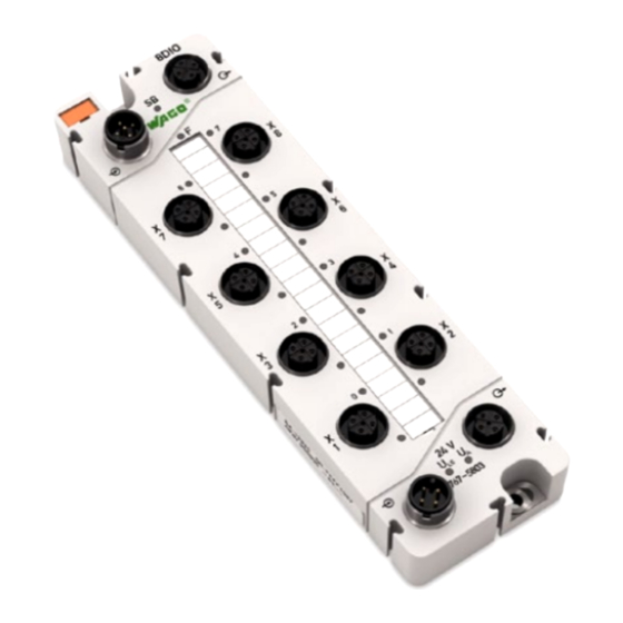
8DIO 24V DC 0,5A (8xM12) Digital Input/Output Module DC 24 V, 0,5 A for WAGO-SPEEDWAY 767 Series
Brand:
WAGO
| Category:
Control Unit
| Size: 4.45 MB
Table of Contents
Table of Contents
3
WAGO-SPEEDWAY 767 Table of Contents
5
1 Notes about this Documentation
6
Validity of These Operating Instructions
6
Copyright
6
Symbols
7
Number Notation
9
Font Conventions
9
Table 1: Number Notation
9
Table 2: Font Conventions
9
2 Important Notes
10
Legal Bases
10
Subject to Changes
10
Personnel Qualification
10
Use in Compliance with Underlying Provisions
11
Technical Condition of Specified Devices
11
Safety Advice (Precautions)
12
Safety Equipment
13
Notes on Operation
14
3 Device Description
15
Connectors
16
Figure 1: Connectors
16
Table 3: Legend for Figure "Connectors
16
Marking Possibilities and Fastening
17
Figure 2: Marking Possibilities and Fastening (Exemplary)
17
Table 4: Legend for Figure "Marking Possibilities and Fastening
17
Display Elements
18
Figure 3: Display Elements (Exemplary)
18
Table 5: Legend for Figure "Display Elements
18
Labeling
19
Figure 4: Labeling (Example)
19
Table 6: Legend for Figure "Labeling
19
Figure 5: Label on the Module
20
Table 7: Description of Manufacturing Number
20
Schematic Diagram
21
Figure 6: Schematic Diagram
21
Dimensions
22
Figure 7: Dimensions of the Module in Millimeters (Exemplary)
22
Technical Data
23
General Information
23
Supply
23
Communication
23
Table 8: Technical Data - General Information
23
Table 9: Technical Data - Supply
23
Table 10: Technical Data - Communication
23
Inputs
24
Table 11: Technical Data - Inputs
24
Input Characteristic
25
Outputs
25
Table 12: Technical Data - Input Characteristic
25
Table 13: Technical Data - Outputs
25
Information on Actuator Selection
26
Operating State Influence on Output
26
Counter 1 and 2 (Configurable)
26
Table 14: Technical Data - Information on Actuator Selection
26
Table 15: Technical Data - Operating State Influence on Output
26
Table 16: Technical Data - Counter 1 and 2 (Configurable)
26
Configurable Functions
27
Table 17: Technical Data - Configurable Functions
27
Configurable Functions for Counters
28
Table 18: Technical Data - Configurable Functions for Counters
28
Diagnostics
29
Process Image
29
Indicators
29
Isolation
29
Table 19: Technical Data - Diagnostics
29
Table 20: Technical Data - Process Image
29
Table 21: Technical Data - Indicators
29
Table 22: Technical Data − Isolation
29
Approvals
30
Standards and Guidelines
31
4 Mounting
32
Information on Mounting
32
Tools and Accessories Required for Mounting
34
Direct Mounting on Your System
35
Figure 8: Mounting the Module on the Grounded System
35
Mounting on a Carrier Rail (Only with WAGO Accessories)
36
Fastening the Carrier Rail Adapter to the Module
36
Figure 9: Fastening to the Carrier Rail Adapter
36
Fastening the Module with Carrier Rail Adapter to a Carrier Rail
37
Figure 10: Mounting the Carrier Rail Adapter (Exemplary)
37
Mounting on a Profile Rail (Only with WAGO Accessories)
38
Fastening the Profile Adapter to the Module
38
Figure 11: Fastening to the Profile Adapter
38
Fastening the Module with Profile Adapter to a Profile Rail
39
Marking and Replacing the Marking Spaces
40
Figure 12: Replacing the Marking Spaces
40
Mounting the Spacer in the Case of Compact Arrangement
41
Figure 13: Attaching a Spacer to a Module
41
Figure 14: Attaching Another Module with a Spacer
42
5 Connecting Data and Supply Cables
43
Notes
43
Required Accessories
44
Connecting the S-BUS Cables
45
Table 23: S-BUS Connection Assignment
45
Figure 15: S-BUS Connected to a Fieldbus Coupler and Modules
46
Connecting the Supply Cable
47
Table 24: Supply Connection Assignment
47
Figure 16: Supply Cable Connected to a Fieldbus Coupler and Modules
48
Connect Sensor/Actuator Cable
49
Table 25: Digital Inputs/Outputs: Connection Assignment
49
Table 26: Counter: Assignment of Channels for Connection Assignment
49
Figure 17: Connectors (Exemplary)
50
6 Commissioning
51
7 Parameterizing
52
Figure 18: Example of an Open DTM, Including Parameters
53
Table 27: DTM Buttons
53
Electronic Type Label
54
Table 28: Information on the Module
54
Diagnostic Overview
55
Figure 19: Example of the Diagnostic Overview of a Module (Information May Differ from the Actual Module)
55
Table 29: Diagnostics Setup
55
Table 30: Information about Existing Module Diagnostics
56
Table 31: Information about Existing Channel Diagnostics
56
Input and Output Parameters
57
Table 32: Overview of Operating Modes
57
DO Module" Mode
58
Table 33: Overview of Adjustable Parameters for the Digital Outputs
58
DI Module" Mode
60
DIO Module" Mode
60
Table 34: Overview of Adjustable Parameters for the Digital Inputs
60
DIO Module with Counter" Mode
61
Table 35: Overview of Adjustable Counter Parameters for the DIO Module
61
Global Settings
63
Parameters of Field Supply
63
Table 36: Overview of Parameters for the Entire Module
63
Table 37: Overview of Adjustable Parameters for the Field Supply
63
Automatic Storage of System Parameters
64
Updating the Firmware
64
8 Process Image
65
DO Mode
67
Input Data
67
Table 38: DO Input Data in the Process Image
67
Output Data
68
Table 39: DO Output Data in the Process Image
68
DI Mode
69
Input Data
69
Table 40: DI Input Data in the Process Image
69
Output Data
70
Table 41: DI Output Data in the Process Image
70
DIO Mode
71
Input Data
71
Table 42: DIO Input Data in the Process Image
71
Output Data
72
Table 43: DIO Output Data in the Process Image
72
DIO Mode + 1 Counter
73
Input Data
73
Table 44: DIO + 1 Counter, Input Data in the Process Image
73
Output Data
74
Table 45: DIO + 1 Counter, Output Data in the Process Image
75
DIO Mode + 2 Counters
76
Input Data
76
Table 46: DIO + 2 Counters, Input Data in the Process Image
76
Output Data
77
Table 47: DIO + 2 Counters, Output Data in the Process Image
78
9 Counter Function
79
Figure 20: Counter Status Depending on the Control Inputs (Gate and Count Direction Input)
79
Control of the Counter Via Inputs and Outputs
80
Table 48: Connection Assignment for the Counter Function
80
Controlling and Monitoring of the Counter Via the Process Data
81
Control Byte
81
Table 49: Control Byte
81
Status Byte
82
Table 50: Status Byte
82
Example of Controlling Two Counters Via the Process Data
83
Table 51: Example of Controlling Two Counters Via Control Byte
83
10 Diagnostics
84
LED Signaling
84
Figure 21: Leds Indicating Operational Messages (Exemplary)
84
Table 52: Operating Messages 1
84
Table 53: Operating Messages 2
86
11 Service
87
Updating the Firmware
87
Replacing the Module
87
Disconnecting the Cables
87
Removing the Module from Your System
88
Removing the Module from the Carrier Rail
88
Figure 22: Removing the Module (with the Carrier Rail Adapter) from the Carrier Rail
88
Removing the Module from the Profile Adapter
89
Connecting the Module
89
Disposal
89
12 Appendix
90
Diagnostic Information
90
Table 54: Diagnostics of the Module
90
Table 55: Diagnostics of the Individual Channels of the Module
90
List of Figures
91
List of Tables
92
Advertisement
Advertisement
Related Products
WAGO 767-5201
WAGO 767-5801/000-800
WAGO 767-5401
WAGO 767-5803/000-800
WAGO 767-4803/000-800
WAGO 767-4807
WAGO 767-9101
WAGO 767-4804/000-800
WAGO 767-1201
WAGO 767-4801/000-800
WAGO Categories
I/O Systems
Control Unit
Power Supply
Switch
Controller
More WAGO Manuals
Login
Sign In
OR
Sign in with Facebook
Sign in with Google
Upload manual
Upload from disk
Upload from URL