Sign In
Upload
Manuals
Brands
WAGO Manuals
Control Unit
767-1501
WAGO 767-1501 Manuals
Manuals and User Guides for WAGO 767-1501. We have
2
WAGO 767-1501 manuals available for free PDF download: Manual, Quick Start Manual
WAGO 767-1501 Manual (260 pages)
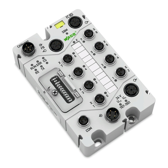
FC CANopen 8DI 24V DC CANopen Fieldbus Coupler
Brand:
WAGO
| Category:
Adapter
| Size: 8 MB
Table of Contents
Table of Contents
3
Table of Contents
5
Table 141: Object 0X1800 - 0X181F
7
Notes about this Documentation
9
Validity of These Operating Instructions
9
Copyright
9
Symbols
10
Number Notation
12
Font Conventions
12
Table 1: Number Notation
12
Table 2: Font Conventions
12
Important Notes
13
Legal Bases
13
Subject to Changes
13
Personnel Qualification
13
Technical Condition of Specified Devices
14
Use in Compliance with Underlying Provisions
14
Safety Advice (Precautions)
15
Safety Equipment
16
Notes on Operation
17
Information on Canopen
18
Network Topology
19
Physical Transmission Technology
20
Wiring with Symmetrical Copper Cable
20
Figure 1: Measuring Principle to Check CAN Bus before Startup
20
Table 3: Measured Values
21
Maximum Bus Lengths in CAN Networks
22
Communication
22
Table 4: Maximum Bus Lengths Dependent on Preset Baud Rate
22
Device Description
23
Table 5: Legend for Figure "Connectors
24
Figure 2: Connectors
24
Connectors
24
Table 6: Legend for Figure "Marking Possibilities and Fastening
25
Marking Possibilities and Fastening
25
Figure 3: Marking Possibilities and Fastening
25
Display Elements
26
Figure 4: Display Elements
26
Table 7: Legend for Figure "Display Elements
26
Operating Elements
28
Figure 5: DIP Switch. All Switches Are Set on "Off" at Delivery
28
Table 8: Default Settings of DIP Switch
28
Table 9: Explanation of DIP Switch
28
Labeling
30
Figure 6: Labeling on the Back Side
30
Table 10: Legend for Figure "Labeling on the Back Side
30
Table 11: Description of Manufacturing Number
31
Figure 7: Label on Fieldbus Coupler
31
Figure 8: Schematic Diagram
32
Schematic Diagram
32
Dimensions
33
Figure 9: Dimensions of Fieldbus Coupler in MM
33
Table 13: Technical Data - System Data
34
Table 12: Technical Data - Device Data
34
System Data
34
Device Data
34
Technical Data
34
Supply
35
Communication
35
Inputs
35
Table 14: Technical Data - Supply
35
Table 15: Technical Data - Communication
35
Table 16: Technical Data - Inputs
35
Table 18: Technical Data - Diagnostics
36
Configurable Functions
36
Table 17: Technical Data - Configurable Functions
36
Diagnostics
36
Process Image
37
Indicators
37
Service Interface COM
37
Isolation
37
Table 19: Technical Data - Process Image
37
Table 20: Technical Data - Indicators
37
Table 21: Technical Data - Service Interface
37
Table 22: Technical Data − Isolation
37
Approvals
38
Standards and Guidelines
39
Mounting
40
Information on Mounting
40
Tools and Accessories Required for Mounting
42
Direct Mounting on Your System
43
Figure 10: Mounting the Fieldbus Coupler on the Grounded System
43
Mounting on a Carrier Rail (Only with WAGO Accessories)
44
Fastening the Carrier Rail Adapter to the Fieldbus Coupler
44
Figure 11: Fastening the Fieldbus Coupler to the Carrier Rail Adapter
44
Fastening the Fieldbus Coupler with Carrier Rail Adapter to a Carrier Rail
45
Figure 12: Mounting the Carrier Rail Adapter
45
Mounting on a Profile Rail (Only with WAGO Accessories)
46
Fastening the Profile Adapter to the Fieldbus Coupler
46
Figure 13: Fastening the Fieldbus Coupler to the Profile Adapter
46
Fastening the Fieldbus Coupler with Profile Adapter to a Profile Rail
47
Replacing the Marker Card and Strip
48
Figure 14: Replacing the Marker Card and Strip
48
Mounting the Spacer in the Case of Compact Arrangement
49
Figure 15: Attaching a Spacer
49
Figure 16: Attaching Another 767 Component to the Fieldbus Coupler
50
Connecting Data and Supply Cables
51
Notes
51
Required Accessories
52
Connecting the Fieldbus Cable
53
Table 23: Canopen Connection Assignment
53
Connecting the Fieldbus Coupler to a CAN Network
54
Figure 17: Connecting Fieldbus to a Fieldbus Coupler
54
Connecting Several Fieldbus Couplers Within a CAN Network
55
Figure 18: Two Fieldbus Couplers Within One Fieldbus Network
55
Connecting the S-BUS Cable
56
Table 24: S-BUS Connection Assignment
56
Figure 19: S-BUS Is Connected to Fieldbus Coupler and I/O Modules
57
Connecting the Supply Cable
58
Table 25: Supply Connection Assignment
58
Figure 20: Supply Cable Connected with Fieldbus Coupler and I/O Modules
59
Table 26: Connection Assignment of Digital Inputs
60
Connecting the Sensor Cables
60
Figure 21: Digital Inputs
61
Connecting the USB Cable
62
Table 27: USB Connection Assignment
62
Figure 22: USB Interface
63
Commissioning
64
Setting the Canopen Station Address
65
Table 28: Default Settings of DIP Switch
65
Figure 23: DIP Switch Set for Station Address 52
66
Setting the Baud Rate
67
Table 29: Assignment of Switch Position to Baud Rate
67
Figure 24: DIP Switches Set for a 500Kbit/S Baud Rated
68
Switching on the Fieldbus Coupler
69
Configuration
70
Process Data
70
EDS Files
71
Figure 25: Example of CODESYS Controller Configuration 1
71
Figure 26: Example of CODESYS Controller Configuration 2
72
PDO Mapping
73
Default PDO Mapping
74
Table 30: 1St Rxpdo Mapping
74
Table 31: 2Nd Rxpdo
75
Table 32: 3Rd Rxpdo
76
Table 33: 4Th Rxpdo
77
Table 34: 1St Txpdo
78
Table 35: 2Nd Txpdo
79
Table 36: 3Rd Txpdo
80
Table 37: 4Th Txpdo
81
Table 39: Mapping Parameters
82
Table 40: Mapping Parameter Structure of Txpdo, Index 0X1A01
82
Table 38: Deactivate PDO Mapping
82
Application-Specific Mapping
82
Table 41: Insert 3Rd Analog Input Channel
83
Table 42: Insert 5Th Analog Input Channel
83
Table 43: Insert 1St Digital Input Module
83
Table 44: Number of Mapping Objects = 3 (Enter into Sub-Index 0)
83
Table 49: Sub Index 1: Setting COB ID of PDO to 0X432 and from Invalid to Valid
84
Table 48: Sub Index 2: "Transmission Type" = 3
84
Table 47: Sub-Index 3: "Inhibit Time" = 0
84
Table 46: Entering "Communication Parameters
84
Table 45: Deactivate PDO
84
Enabling the Analog Input Data
85
Inputs on the Canopen Fieldbus Coupler
85
Delayed I/O Module Start-Up
86
Figure 27: Fieldbus Coupler Response to Delayed Start-Up
87
S-BUS Disruption During Continuous Operation
88
Activating Data Exchange
88
Diagnostic Messages from I/O Modules
89
Diagnostics
89
Table 50: Description of Error Messages
90
Error Messages (Emergency)
90
Object Directory
93
Table 51: Structure of Canopen Object Directory
94
Communication Profile Area
95
Table 52: Communication Profile Objects
95
Canopen State Diagram
97
Initialization
97
Figure 28: Canopen State Diagram
97
Pre-Operational
98
Operational
98
Stopped
98
Figure 30: Txpdo
99
Figure 29: Rxpdo
99
Process Data Object (PDO)
99
Canopen Communication Objects
99
Service Data Object (SDO)
100
Initiate SDO Download
101
Figure 31: Rxsdo and Txsdo
101
Figure 32: Initiate SDO Download
101
Table 53: Description of "Initiate SDO Download" Protocol
102
Download SDO Segment
103
Figure 33: Download SDO Segment
103
Table 54: Description of the "Download SDO Segment" Protocol
103
Initiate SDO Upload
104
Figure 34: Initiate SDO Upload
104
Table 55: Description of "Initiate SDO Upload" Protocol
105
Upload SDO Segment
106
Figure 35: Upload SDO Segment
106
Table 56: Description of the "Upload SDO Segment" Protocol
106
Table 58: Description of Error in Bytes
107
Table 59: Error Messages Arising from the Abort SDO Protocol
107
Abort SDO Transfer
107
Figure 36: Abort SDO Transfer
107
Table 57: Description of the Abort SDO Protocol
107
Examples of Sdos
109
Table 60: Read Index 0X1000
109
Table 61: Read Index 0X1008
110
Table 62: Read Index 0X5300
110
Node Guarding
111
Table 63: Describe Index 0X6200
111
Heartbeat Monitoring
113
Synchronization Object, SYNC
114
SYNC Monitoring
114
Figure 37: Sync Protocol
114
Figure 38: EMCY Protocol
115
Figure 39: Start Remote Node
115
Start Remote Node
115
Emergency Object (EMCY)
115
Network Management Protocol
115
Stop Remote Node
116
Enter Pre-Operational
116
Figure 40: Stop Remote Node
116
Figure 41: Enter Pre-Operational
116
Reset Node
117
Figure 42: Reset Node
117
Figure 43: Node Guarding Protocol
118
Error Control Protocols
118
Node Guarding Protocol
118
Heartbeat Protocol
119
Bootup Protocol
119
Figure 44: Heartbeat Protocol
119
Figure 45: Bootup Protocol
119
Figure 46: Leds Which Display Status Messages
120
Table 64: Status Messages of the RX and TX Leds
120
Diagnostics
120
Canopen Status Messages
120
LED Signaling
120
Table 65: Status Messages of the ERR LED
121
Table 66: Status Messages of the RUN LED
122
Operational Messages of the Fieldbus Coupler
123
Figure 47: Leds Which Display Operational Messages
123
Table 67: Operational Messages of the Fieldbus Coupler
123
Error Messages from the Fieldbus Coupler Via LED Signals
125
Figure 48: Indicator of Blink Codes Via CS LED
125
Progression of Blink Sequence
126
Table 68: Overview of the Blink Codes
126
Example of an Error Message Via Blink Code
127
Meaning of the Blink Codes and Procedures for Correcting Them
128
Table 69: List of Error Groups
128
Table 70: Group Number 1: S-BUS Error
129
Table 71: Group Number 2: S-BUS Warnings
131
Table 72: Group Number 5: General Internal Hardware Errors
132
Table 73: Group Number 6: General Internal Hardware Warnings
132
Table 74: Group Number 7: General Software Errors
132
Table 75: Group Number 8: General Software Warnings
135
Table 76: Group Number 9: Specific Hardware Errors
135
Table 77: Group Number 11: Canopen-Specific Errors
136
Table 78: Group Number 12: Canopen-Specific Warnings
136
Table 79: Group Number 13: Firmware Loader Error
137
Table 80: Group Number 14: Error with Firmware Download
138
Readout of Blink Codes Using WAGO Dtms
139
Figure 49: Example of the Blink Code Display under the "Blink Code" Parameter in
139
Parameterizing
140
Figure 50: Start Screen of Wagoframe CD
141
Installing the FDT/DTM Components
141
Figure 51: Window for Product Selection 1
142
Figure 52: Window for Product Selection 2
143
Figure 53: Wagoframe Logo
144
Figure 54: "Device Selection Wizard
144
Starting Wagoframe
144
Expansion of Device Catalog to Include 767 Components
145
Figure 55: "Query Wagoframe" Dialog Box (Exemplary)
145
Figure 56: View of Device Catalog (Example)
145
Setting up Network Manually
146
Adding the Communication DTM
146
Figure 57: Adding the Communication DTM (Example)
146
Figure 58: Selecting the Communication DTM (Example)
147
Selecting the Communications Interface for Wagoframe
148
Figure 59: the DTM for the Interface Configuration (Example)
148
Adding a Fieldbus Coupler
149
Figure 60: Adding a Fieldbus Coupler (Example)
149
Figure 62: Adding the I/O Modules (Example)
150
Adding the I/O Modules
150
Figure 61: Adding the Fieldbus Coupler (Example)
150
Figure 63: Selecting an I/O Module (Example)
151
Figure 64: Two Added I/O Modules
151
Online and Offline Parameter Setting
152
Offline Parameter Setting
152
Figure 65: Opening the Configuration Interface (Offline, Example)
152
Online Parameter Setting
153
Figure 66: Setting up a Connection to the Fieldbus Coupler (Example)
153
Figure 67: Opening the Configuration Interface (Online, Example)
154
The "Additional Functions" and "Scan" Selections
155
Changing the Bus Address
156
Figure 68: Opening the "List of Bus Nodes" Window (Example)
156
Figure 69: Assigning New Bus Addresses for the I/O Modules (Example)
157
Table 81: Service Page
158
Figure 70: Service Page (Example)
158
Service Page
158
Set up Network Automatically
159
Figure 71: Setting up the Network (Example)
159
Figure 72: Components Connected to the 767 Node (Example)
159
Life List
160
Figure 73: Searching for Connected I/O Modules Using the Life List (Example)
160
Figure 74: Connected I/O Modules of the Selected Fieldbus Coupler (Example)
161
System Update
162
Notes on System Update
162
Service Communication Via USB
162
15.6.5.2.1 Adding the Communication DTM USB
162
Figure 75: Select COM Port
163
Figure 76: Adding the Communication DTM
163
Figure 77: Selecting the Communication DTM USB
164
Figure 79: System Update 1 (Example)
165
Figure 78: Adding the DTM System Update
165
15.6.5.2.2 Adding the DTM System Update
165
15.6.5.2.3 Go Online to 767 Nodes Using Update DTM
166
15.6.5.2.4 Updating the 767 Components
166
Figure 80: Go Online to 767 Node (Example)
166
Figure 81: Package Management 1 (Example)
167
Figure 82: Package Management 2 (Example)
168
Figure 83: System Update 2 (Example)
169
Figure 84: System Update 2 (Example)
170
Table 82: Buttons
170
Figure 85: System Update 3 (Example)
171
Parameterization
172
Figure 86: Example of an Opened DTM with the Available Parameters
173
Table. 83: DTM Buttons
173
Table 86: Time Settings
174
Table 85: General Fieldbus Information
174
Table 84: Information about the Fieldbus Coupler
174
General Parameters
174
Table 87: S-BUS Master
175
Table 88: Display of Errors
175
Figure 87: System Parameter Handling 1 (Example)
176
Figure 88: System Parameter Handling 2 (Example)
177
Table 89: Overview of Adjustable Parameters for "System Parameter Handling
177
Table 90: Overview of System Event History
179
Table 91: Overview of Diagnostics History
180
Canopen-Specific Parameters
181
Table 92: Overview of Canopen-Specific Parameters
181
Diagnostic Overview and Parameters of Inputs
182
Figure 89: Diagnostic Overview of the Fieldbus Coupler (Example)
182
Table 93: Diagnostic Setup
182
Table 95: Adjustable Parameters of the Digital Inputs
183
Table 94: Information about Existing Module Diagnostics
183
Table 96: Adjustable Parameters for the Entire Fieldbus Coupler
184
Table 97: Adjustable Parameters of the Field Supply
185
Service
186
Updating the Firmware
186
Replacing the Fieldbus Coupler
186
Disconnecting the Cables
186
Removing the Fieldbus Coupler from Your System
187
Removing the Fieldbus Coupler from the Carrier Rail
187
Figure 90: Removing the Fieldbus Coupler (with the Mounting Rail Adapter) from the Mounting Rail
187
Removing the Fieldbus Coupler from the Profile Adapter
188
Connecting a New Fieldbus Coupler
188
Disposal
188
Use in Hazardous Environments
189
Table 98: Legend for Figure "Side Marking Example for Approved WAGO
190
Figure 91: Side Marking Example for Approved WAGO SPEEDWAY 767 Series Fieldbus Coupler According to ATEX and Iecex
190
Marking for Europe According to ATEX and IEC-Ex
190
Marking Configuration Examples
190
Installation Regulations
191
Special Conditions for Safe Use (ATEX Certificate BVS 15 ATEX E098X)
192
Special Conditions for Safe Use (IEC Ex Certificate Iecex BVS 15.0083X)
193
Accessories
194
S-BUS Cable, Assembled on One End
194
Table 99: S-BUS Cable, Assembled on One End, B Coded
194
Table 100: S-BUS Cable, Assembled on One End, B Coded, Suitable for Drag Chains
195
S-BUS Cable, Assembled on One End, Suitable for Drag Chains
195
S-BUS Cable, Assembled on both Ends
196
Table 101: S-BUS Cable, Assembled on both Ends, B Coded
196
S-BUS Cable, Assembled on both Ends, Suitable for Drag Chains
197
S-BUS Cable, Not Fitted with Connectors
197
Table 102: S-BUS Cable, Assembled on both Ends, B Coded, Suitable for Drag
197
Table 103: S-BUS Cable, Not Fitted with Connectors
197
Table 105: S-BUS Terminator and USB Cable
198
Table 106: Accessories for S-BUS
198
S-BUS Cable, Not Fitted with Connectors, Suitable for Drag Chains
198
Table 104: S-BUS Cable, Not Fitted with Connectors, Suitable for Drag Chains
198
Accessories for S-BUS
198
S-BUS Terminator and USB Cable
198
Power Supply Cable, Assembled on One End
199
Table 107: Power Supply Cable, Assembled on One End, a Coded
199
18.10 Power Supply Cable, Assembled on both Ends
200
18.11 Power Supply Cable, Not Fitted with Connectors
200
Table 108: Power Supply Cable, Assembled on both Ends, a Coded
200
Table 109: Power Supply Cable, Not Fitted with Connectors
200
18.12 Accessories for Power Supply Cable
201
18.13 Canopen, Devicenet Cable, Assembled on One End
201
Table 110: Accessories for Power Supply Cable
201
Table 111: Canopen, Devicenet Cable, Assembled on One End, a Coded
201
Table 113: Accessories for Canopen and Devicenet
202
Table 114: Torque Wrench M8 and M12
202
Canopen, Devicenet Cable, Assembled on both Ends
202
Table 112: Canopen, Devicenet Cable, Assembled on both Ends, D Coded
202
18.16 Torque Wrench M8 and M12
202
18.15 Accessories for Canopen and Devicenet
202
18.17 Carrier Rail / Profile Adapters and Spacer Module
203
18.18 Protective Caps
203
Table 115: Carrier Rail / Profile Adapters and Spacer Module
203
Table 116: Protective Caps
203
Appendix
204
Canopen Objects of the Fieldbus Coupler
204
Object 0X1000, Device Type
204
Table 117: Object 0X1000
204
Object 0X1001, Error Register
205
Table 118: Object 0X1001
205
Table 119: Explanation of the Object
205
Table 121: Object 0X1005
206
Object 0X1005, COB-ID SYNC Message
206
Table 120: Object 0X1003
206
Object 0X1003, Pre-Defined Error Field
206
Object 0X1006, Communication Cycle Period
207
Object 0X1008, Manufacturer Device Name
207
Object 0X1009, Manufacturer Hardware Version
207
Object 0X100A, Manufacturer Software Version
207
Table 122: Object 0X1006
207
Table 123: Object 0X1008
207
Table 124: Object 0X1009
207
Table 125: Object 0X100A
207
Object 0X100C, Guard Time
208
19.1.10 Object 0X100D, Life Time Factor
208
Table 126: Object 0X100C
208
Table 127: Object 0X100D
208
Table 128: Object 0X1010
209
19.1.11 Object 0X1010, Store Parameters
209
19.1.12 Object 0X1011, Restore Default Parameters
210
19.1.12.1 Sub-Index 1 - Permanent Creation of Default Parameters
210
Table 129: Object 0X1011
210
19.1.12.2 Sub-Index 4 - One-Time Creation of Default Parameters
211
19.1.13 Object 0X1014, COB ID Emergency Object
211
Table 130: Object 0X1014
211
19.1.14 Object 0X1015, Inhibit Time Emergency Object
212
Table 131: Object 0X1015
212
19.1.15 Object 0X1016, Consumer Heartbeat Time
213
19.1.16 Object 0X1017, Producer Heartbeat Time
213
Table 132: Object 0X1016
213
Table 133: Object 0X1017
213
19.1.17 Object 0X1018, Identity Object
214
Table 134: Object 0X1018
214
Table 136: Object 0X1029
215
Table 135: Object 0X1029
215
19.1.18 Object 0X1029, Error Behavior
215
19.1.19 Object 0X1200 - 0X1201, Server SDO
216
Table 137: Object 0X1200 - 0X1201
216
Object 0X1400 - 0X141F, Receive PDO Communication Parameter
217
Table 138: Object 0X1400 - 0X141F
217
Table 139: "Transmission Type
218
Object 0X1600 - 0X161F, Receive PDO Mapping Parameter
219
Table 140: Object 0X1600 - 0X161F
219
Parameter
220
Table 142: "Transmission Type
221
Object 0X1A00 - 0X1A1F, Transmit PDO Mapping Parameter
223
Table 143: Object 0X1A00 - 0X1A1F
223
Manufacturer-Specific Profile Area, Object 0X2000 - 0X5Fff
224
Object 0X37F1, Fieldbus Coupler CS LED Flash Signals
224
Table 144: Object 0X37F0
224
Object 0X37F5, Fieldbus Coupler Diagnostics
225
Table 145: Object 0X37F5
225
Object 0X37F6, Fieldbus Coupler Diagnostic Acknowledgement
226
Table 146: Object 0X37F6
226
Object 0X5000, Read Input Process Image
227
Table 147: Object 0X5000
227
Object 0X5001, Write Output Process Image
228
Table 148: Object 0X5001
228
Object 0X5200, Coupler Configuration Object
229
Table 149: Object 0X5200
229
0X5202 Module Configuration Object
230
Object 0X5300 - 0X5340, Input Data of I/O Modules
231
Table 150: Object 0X5300 - 0X5340
231
Object 0X5400 - 0X5440, Output Data of the I/O Modules
233
Table 151: Object 0X5400 - 0X5440
233
Table 152: Standard Device Profile
235
Standard Device Profile Area - DS 401, from Object 0X6000
235
Object 0X6000, Digital Inputs
237
Object 0X6005, Global Interrupt Enable Digital, 8 Bit
237
Table 153: Object 0X6000
237
Table 154: Object 0X6005
237
Object 0X6006, Interrupt Mask any Change, 8 Bit
238
Table 155: Object 0X6006
238
Object 0X6007, Interrupt Mask Low-To-High, 8 Bit
239
Table 156: Object 0X6007
239
Object 0X6008, Interrupt Mask High-To-Low, 8 Bit
240
Table 157: Object 0X6008
240
Object 0X6200, Digital Outputs
241
Object 0X6206, Error Mode Output, 8 Bit
241
Table 158: Object 0X6200
241
Table 159: Object 0X6206
241
Table 160: Object 0X6207
242
Object 0X6207, Error Value Output, 8 Bit
242
Object 0X6401, Analog Inputs, 16 Bit
243
19.3.10 Object 0X6411, Analog Outputs, 16 Bit
243
Table 161: Object 0X6401
243
Table 162: Object 0X6411
243
19.3.11 Object 0X6421, Analog Input Interrupt Trigger Selection
244
Table 163: Object 0X6421
244
Table 164: Object 0X6421
244
19.3.12 Object 0X6423, Analog Input Global Interrupt Enable
245
19.3.13 Object 0X6424, Analog Input Interrupt Upper Limit Integer
245
Figure 92: Upper Threshold Value
245
Table 165: Object 0X6423
245
Table 166: Object 0X6424
245
Table 167: Object 0X6425
246
19.3.14 Object 0X6425, Analog Input Interrupt Lower Limit Integer
246
Figure 93: Lower Threshold Value
246
19.3.15 Object 0X6426, Analog Input Interrupt Delta Unsigned
247
Table 168: Object 0X6426
247
Object 0X6427, Analog Input Interrupt Negative Delta Unsigned
248
Table 169: Object 0X6427
248
Object 0X6428, Analog Input Interrupt Positive Delta Unsigned
249
Table 170: Object 0X6428
249
Table 172: Object 0X6444
250
19.3.18 Object 0X6443, Analog Output Error Mode
250
Table 171: Object 0X6443
250
19.3.19 Object 0X6444, Analog Output Error Value Integer
250
19.3.20 Object 0X67Fe, Error Behavior
251
19.3.21 Reserved Range
251
Table 173: Object 0X67Fe
251
List of Figures
252
List of Tables
255
Advertisement
WAGO 767-1501 Quick Start Manual (44 pages)
Fieldbus Coupler CANopen, 8 DI, 24 V DC For WAGO SPEEDWAY 767
Brand:
WAGO
| Category:
Control Unit
| Size: 2 MB
Table of Contents
Introduction
2
Table of Contents
3
1 Safety
4
Notes on this Quick-Start Guide
4
Explanation of Symbols
5
Validity of this Quick-Start Guide
7
Use in Compliance with Underlying Provisions
7
Personnel Qualification
7
Basic Safety Information
8
Safety Equipment
9
Technical Condition of the 767 Components
10
Notes on Operation
10
2 Description
11
Accessories
11
3 Connection
13
Setting the Canopen Station Address
17
Setting the Baud Rate
19
4 PLC Configuration in Codesys
20
Configuring the Fieldbus Node
20
5 PLC Program
23
6 Wagoframe
24
Installation
25
Starting up the Fieldbus Coupler
30
Operation
31
7 System Update
36
Adding the DTM System Update
37
Go Online to 767 Nodes Using Update DTM
38
Updating the 767 Components
39
Advertisement
Related Products
WAGO 767-1201
WAGO 767-5803
WAGO 767-4803/000-800
WAGO 767-4802/000-800
WAGO 767-4803
WAGO 767-4807/000-800
WAGO 767-5401
WAGO 767-4801/000-800
WAGO 767-5803/000-800
WAGO 767-5801/000-800
WAGO Categories
I/O Systems
Control Unit
Power Supply
Switch
Controller
More WAGO Manuals
Login
Sign In
OR
Sign in with Facebook
Sign in with Google
Upload manual
Upload from disk
Upload from URL