Sign In
Upload
Manuals
Brands
Baumuller Manuals
Measuring Instruments
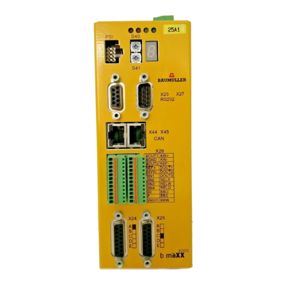
b maXX BM3000
User Manuals: Baumuller b maXX BM3000 Operating
Manuals and User Guides for Baumuller b maXX BM3000 Operating. We have
2
Baumuller b maXX BM3000 Operating manuals available for free PDF download: Operating Manual, Instruction Handbook Manual
Baumuller b maXX BM3000 Operating Manual (822 pages)
Parameter
Brand:
Baumuller
| Category:
Measuring Instruments
| Size: 11 MB
Table of Contents
Table of Contents
3
Prodrive Power Unit
3
Torque Monitoring
3
Prodrive Analog Outputs
5
Current Controller Adaption
7
Prodrive Current Controller
7
Prodrive DC Link Controller
7
Prodrive Flux Controller
7
Two-Level Controller with Relative Thresholds
7
Two-Level-Controller with Absolute Thresholds
7
1 General
11
Information about the Parameter Manual
11
Explanation of Symbols
12
Limitation of Liability
13
Copyright
13
Other Applicable Documents
14
Guarantee Conditions
14
Customer Service
14
Terms Used
14
2 Commissioning Bm25Xx
15
Safety Information
16
Voltage Test
17
Requirements for the Electrical Supply
17
Preparations
18
Communication Via Ethercat
20
Switch-On Sequence
25
Performing the Commissioning
26
Prodrive Navigation Dataset Management
37
Prodrive: Navigation Autotuning Current Controller
38
Prodrive: Autotuning Current Controller
39
Prodrive Navigation - Find Notch Position
40
Prodrive: Navigation Ramp Function Generator
42
3 Commissioning Bm3Xxx
45
Safety Information
46
Voltage Test
47
Requirements for the Electrical Supply
47
Preparations
48
Communication Via the Service Cable
51
Communication Via Ethercat
52
Switch-On Sequence
57
Performing the Commissioning
58
Prodrive: Rastlage Suchen, Antriebsmanager
73
4 Description of the Software Modules and Parameters
77
Cycle Times of the Software Modules
77
Structure of the Parameter Overviews
78
System
80
System Control
80
Parameter Overview
80
Description of the Parameters
81
Display
90
Parameter Overview
90
Description of the Parameters
90
Configuration
91
Power Unit
91
Prodrive Power Unit
92
Parameter Overview
92
Description of the Parameters
94
Motor
111
Motor Identification Plate
111
Torque Limits
111
A) Asynchronous Motor: Torque Limit above B) Asynchronous Motor: Overlap of Several Limits
112
Torque Monitoring
113
Torque Threshold
113
Maximum Permissible Speed (Electrical Conditioned)
114
Prodrive Motor
115
Parameter Overview Motor
115
Prodrive Motor General
115
Description of the Parameters
118
Modes of the "Max. Torque Current 19.8 at the Synchronous Motor
121
A) Field Current Dependence (External Total Current Limit Is Not Assumed)
121
B) External Total Current Limit Dependence (Field Weakening Is Not Assumed)
121
Max. Torque Current" Modes 19.8 at the Asynchronous Motor A) Field Current Dependence (no External Total Current Limit Is Assumed). B) External Total Current Limit Dependence (Field Weakening Is Not Assumed)
122
Synchronous Motor
148
Prodrive Synchronous Motor
148
Asynchronous Motor
149
Prodrive Asynchronous Motor
149
Lh-Characteristic
149
Prodrive Lh-Characteristic
151
Parameter Overview Lh-Characteristic
151
Description of the Lh-Characteristic Parameters
152
Synchronous Motor with Interior Permanent Magnet
153
Control
153
Commissioning
154
Identification of the Nonlinear Parameters
155
Field Weakening at IPMSM
155
Parameter Overview
157
Description of the Parameters
158
Encoder
162
Encoder Monitoring
163
Prodrive Encoder
166
Encoder Optimization
166
Encoder Correction
167
Encoder Accuracy and Excentricity
170
Resolver Synchronization
171
Parameter Overview
172
Description of the Parameters
174
Autotuning of Current Controller
199
Prodrive Autotuning of the Current Controller
200
Parameter Overview
200
Description of the Parameters
201
Autotuning of Position / Speed Controller
207
Ks Determination
207
Prodrive Ks Determination
210
Parameter Overview Ks Measurement
210
Prodrive Ks Measuring
210
Description of the Ks Measurement Parameters
211
Autotuning Asynchronous Motor
215
Identification Lh Characteristic
215
Digital Inputs
216
Prodrive Digital Inputs
216
Only (138.1 Bit 1 = 1, Bit 3 = 0)
216
Parameter Overview
217
Parameter Description
217
Digital Outputs
222
Prodrive Digital Outputs
222
Parameter Overview
222
Description of the Parameters
223
Analog Inputs
226
Description of the Analog Inputs
226
Prodrive Analog Input
228
Parameter Overview
228
Description of the Parameters
228
Analog Outputs
230
Description of the Analog Outputs
230
Prodrive Analog Outputs
230
Parameter Overview
231
Description of the Parameters
232
Filter
236
Prodrive Filter
236
Prodrive Filter
239
Parameter Overview
239
Description of the Parameters
240
Fieldbus Communication
244
Parameter Ids for the Real Time Lists
247
Access Counter for each Real Time List
247
Parameter Overview
247
Description of the Parameters
248
Measuring Encoder Function
256
Prodrive Measuring Encoder
258
Parameter Overview
258
Description of the Parameters
259
Freely Programmable PID Controller
270
Parameter Overview
271
PID Controller Functional Diagram
271
Controller 1
271
Description of the Parameters
273
Master-Slave Torque Coupling
280
Structure of the Control of the Torque Coupling at Connecting the Torque Coupling as Torque Additional Set Value
282
Parameter Overview
284
Description of the Parameters
285
Friction Compensation
291
Description of the Friction Compensation
291
Identification of the Friction Torque Curve
294
Parameter Overview
294
Description of the Parameters
295
Synchronization
298
Parameter Overview
298
Description of the Parameters
298
Configurable Status Word
301
Parameter Overview
302
Description of the Parameters
303
Softdriveplc
307
Overview Softdriveplc
307
Function
307
Limitations
308
Tasks
309
Programming Interface
309
Parameter Overview
310
Description of the Parameters
311
DS402 Factor Group
318
General Information
318
Factor Group Effect of Position Weighting
320
Factor Group Effect of the Speed and Acceleration Weighting
321
Prodrive DS402
323
Parameter Overview
323
Prodrive Factor Group and Touch Probe DS402
323
Description of the Parameter
325
Management
330
Drive Management
330
State Machine of the Device Controller
334
Parameter Overview
340
Description of the Parameters
341
Data Set Management
362
General
362
Command Interface
362
Organization of the Parameters in the Data Sets
363
Delivered State
364
Switch-On Behavior
364
Changing, Loading, Copying and Storing Parameters
364
Identification of Parameter Set and Data Sets
364
Functions of the Data Set Management System
365
Data Set Commands and Possible Error Messages
366
Changeover to Data Set 1 to 7
368
Overview of the Data Set Management Commands
368
Parameter Overview
369
Description of the Parameters
370
Brake Management
374
Description of the Brake Management System
374
Brake Watchdog
379
Prodrive Brake Management
380
Parameter Overview
380
Description of the Parameters
381
Error Management
386
Parameter Overview
386
Description of the Parameters
387
Signal Bus
391
Messages on the Signal Bus
391
Supply Ready for Use
391
Chopper Resistor on
391
Prodrive Signal Bus
392
Parameter Overview
392
Description of the Parameters
392
Set Value Manager
394
Parameter Overview
395
Description of the Parameters
395
Set Value Generators
399
Ramp Function Generator
399
Optional Interpolation of the Ramp Function Generator Input Set Value
403
Prodrive Ramp Function Generator
405
Parameter Overview
406
Description of the Parameters
408
Set Value Generator
417
Parameter Overview
417
Speed Set Value Sequence for Set Value Generator
417
Description of the Parameters
418
Error Reaction Controlled Stop
421
Error Reaction Return Motion
422
Parameter Overview
422
Description of the Parameters
423
Cam Generator
426
Time Control Via the Table Index
426
Time Control with Virtual Master Axis
426
Parameter-Controlled Processing
427
Setting Options of Cam Generator
428
State Machine of the Cam Generator
431
Limiting of Output Value
432
Handling the Cam Data
432
Parameter Overview
433
Description of the Parameters
433
Motor Potentiometer
437
Parameter Overview
437
Description of the Parameters
438
Controllers
441
Position / Speed Controller
441
Block Diagram of the Speed Controller When in Speed Control (18.4 = 13)
443
Block Diagram of the Position /Speed Controller When in Position Control (18.4 = 12)
444
Physical Units in the Control Circuit
445
Block Diagram of the Position / Speed Controller When in Torque Control
445
The Factor Ks
446
Block Diagram of the Position / Speed Controller Module When in Synchronous Operation with a Real Master Shaft
446
Position / Speed Controller Adaption
447
Cyclical Ks Adaption
448
Prodrive Position / Speed Controller
449
Parameter Overview of Position / Speed Controller
451
Description of the Parameters
453
Current Controller
469
Current Prediction
469
Dead Time Compensation
469
Torque Current Limiting
470
Torque Current Limit "Lsq" at the "Current Mode" of the Synchronous Motor
472
A) Dependent of the Field Current (the External Total Current Limit Is Assumed)
472
B) Dependent of the External Total Current Limit (Field Weakening Is Not Assumed)
472
B) Dependent of External Total Current Limit (Field Weakening Is Not Assumed)
473
Torque Current Limit "Lsqlim" at "Standard Load Mode" of the Asynchronous Motor
473
A) Dependent of the Field Current (External Total Current Limit Is Not Assumed). B) Dependent of External Total Current Limit (Field Weakening Is Not Assumed)
473
A) Dependent of the Field Current (External Total Current Limit Is Not Assumed)
473
B) Dependent of the External Total Current Limit (Field Weakening Is Not Assumed)
475
Feedforward
477
Current Controller Adaption
477
Pulse Width Modulation
478
Prodrive Current Controller
479
Overview of Current Controller Parameters
481
Description of Current Controller Parameters
482
Current Controller
482
DC Link Controller
490
Description of the DC Link Controller
490
Prodrive DC Link Controller
490
Reactive Current Brakes
490
Short Circuit Brake
491
Parameter Overview of the DC Link Controller
491
Description of the DC Link Controller Parameter
492
Field Weakening Controller
494
Breakdown Torque
498
Parameter Overview
501
Description of the Field Weakening Parameters
502
Two-Level Controller
506
General
506
Two-Level Controller with Absolute Thresholds
507
Two-Level Controller with Relative Thresholds
508
Combination of the Operating Modes Absolute and Relative Thresholds
508
Sign-Independent Monitoring
510
Linking of the Controller Output with the Target Parameter
510
Parameter Overview of the Two-Level Controller
511
Description of the Two-Level Controller Parameter with Absolute Thresholds
512
Description of the Two-Level Controller Parameter with Relative and Absolute Thresholds
514
Flux Controller
518
Prodrive Flux Controller
518
Parameter Overview of the Flux Controller
518
Description of the Flux Controller Parameters
519
Controller Adaptations
520
Parameter Overview of the Controller Adaptations
521
Description of the Controller Adaptations Parameters
521
Adaption EMF Feed Forward
523
Adaption Torque Monitoring
524
Ks Adaption
525
Adaption of the Saturation
526
Compensation Dead Time Voltages
527
Temperature Adaption Motor Resistances
527
Temperature Adaption Slip Frequency
527
Operating Modes
530
Operating Modes General
530
Moving to Positive Stop Command
531
Prodrive General Parameters
534
Parameter Overview
534
Description of the Parameters
535
Target Position Setting (Positioning) Mode
549
Controlling the Positioning
549
Positioning Data
550
Bits in the Control Word / Status Word
551
Actions on the Rising Edge of "New Set Value
552
Sequence of Events for Positioning Handshake with "Single Set Value
552
Sequence of Events for Handshake with "Set of Set Values
554
Hardware Limit Switches
555
Software Limit Switches
557
Target Specifications
557
Change of Operating Mode to Positioning
558
Halting a Running Positioning Task
558
Aborting a Running Positioning Task
559
Set Value Profiles
559
Comparison of Motion Profiles for Positioning
560
Control by Means of the "Start Positioning" Method
562
Parameter Overview
566
Description of the Parameters
567
Operating Mode Homing
583
Procedure of a Homing under Consideration of Zero Pulse or Zero Angle
583
Shifting the Zero Angle
584
Maximum Distance for Zero Pulse Detection
584
Procedure of a Homing to Switch Only
584
Homing Without Setting the Home Position
585
Automatic Setting of the Absolute Value Offset at Homing
586
Notes
586
Homing Method 1 (Neg. Limit Switch)
587
Homing Method 2 (Pos. Limit Switch)
587
Homing Methods 3 and 4 (Pos. Zero Point Changeover Switch)
588
Homing Methods 5 and 6 (Neg. Zero Point Changeover Switch)
589
Homing Methods 7 to 14 (Reference Switch)
590
Homing Methods 15 and 16 (Reserved)
591
Homing Methods 17 to 30 (Without Zero Pulse or Zero Angle)
591
Homing Methods 31 and 32 (Reserved)
592
Homing Methods 33 and 34 (Zero Pulse Only)
592
Homing Method 35 (Set Home Position Only)
593
Manufacturer Specific Homing Methods
593
Command Set Home Position
594
Parameter Overview
594
Description of the Parameters
595
Manual Drive Operation
603
Parameter Overview
604
Description of the Parameters
604
Operation Mode Spindle Positioning (M19 Command)
607
Parameter Overview
611
Description of the Parameters
612
Position Control with Synchronous Set Value Specification
616
Parameter Overview
617
Description of the Parameters
618
Operating Mode Synchronous Operation
627
Parameter Overview
629
Description of the Parameters
630
Operating Mode Notch Position Search
639
Prodrive Notch Position Search
641
Parameter Overview
641
Description of the Parameters
642
Notch Position Search with the Injection Method
645
Parameter Survey and Parameter Description
645
Error Response at Notch Position Search 2
645
Sensorless Control for Synchronous Machines
646
General Constraints of Sensorless Control with the Injection Procedure
647
Commissioning at the Sensorless Operation of the Synchronous Machine
647
Vibration Damping
648
Motor Diagnosis
648
Parameter Overview
649
Description of the Parameters
650
Sensorless Control for Asynchronous Motors (Open Loop)
655
Sensorless Control
655
Catch on Fly
656
Parameter Overview
657
Description of the Parameters
658
Operating Mode U-F Characteristic
660
Compensating Controller for Acceleration
661
Current Control
662
Parameter Overview
662
Description of the Parameters
664
Operation Mode Coupled Operation
669
Transmission of Master Axis Position
671
Transmission of the Curve Data
672
Changing the Chaining Sequence
673
Definition of the Starting Segment
674
Synchronization
674
Use of the Output-Sided Gear
676
Overlaying Using an Additional Movement
676
Intermediate Buffering of Curve Segments
677
Real Master Axis
679
Flexible Segments
680
Parameter Overview
680
Description of the Parameter
682
Diagnosis
690
Parameter Overview Diagnosis
690
Description of the Diagnosis Parameters
691
Oscilloscope Function
700
Parameter Overview
700
Software Function FFT Analyzer
707
Parameter Overview
707
Description of the Parameters
708
Optimization
714
Automatic Controller and Filter Setting
714
Torque Ripple Compensation
715
Parameter Overview
715
Description of the Parameters
716
Monitoring
717
Field Angle Monitoring
717
Parameter Overview
717
Description of the Parameters
717
Position Error Monitoring
719
Parameter Overview
719
Description of the Parameters
720
Overload Monitoring of the Power Unit
723
Ixt Model
723
Temperature Model
727
Real Power Limit
730
Temperature Monitoring of the Motor
731
Overload Monitoring of the Motor
731
General Information
731
Speed Variable L T Overload Monitoring
735
Monitoring of the Single Phases
738
5 Error Messages and Troubleshooting
741
Behavior in Case of Errors
741
Monitoring Functions
742
Monitoring Function - Explanations
744
Error Detection
746
Error Handling
746
Error Reset
746
Error Descriptions
747
6 Summary of All Parameters
771
Anhang A - Abbreviations
807
Table of Figures
809
Table of Figures
810
Index
815
Overview of Revisions
819
Document No.: 5.12001.07 of
820
Advertisement
Baumuller b maXX BM3000 Instruction Handbook Manual (220 pages)
Mains rectifier/Compact servo unit
Brand:
Baumuller
| Category:
Servo Drives
| Size: 8 MB
Table of Contents
Table of Contents
3
Dimensions BM3200, BM3300
3
1 General
7
Information on this Instruction Handbook
7
Key to Symbols
7
Limitation of Liability
8
Copyright Protection
9
Applicable Documents
9
Spare Parts
10
Disposal
10
Guarantee Provisions
10
Customer Service
10
Terms Used
10
2 Safety
11
Contents of the Instruction Handbook
11
Changes and Modifications to the Device
11
Appropriate Use
12
Responsibility of the Operating Company
13
Protective Devices
13
Training of the Personnel
14
Personal Protective Equipment
15
Special Hazards
16
Fire Fighting
17
Safety Equipment
18
Behavior in Hazardous Situations or at Accidents
18
Signs and Labels
19
Signs and Labels BM3200, BM3300
20
Signs and Labels BM3000
21
Signs and Labels BM3300 with Safety Level
22
3 Technical Data
23
Dimensions
23
Dimensions BM3000
24
Dimensions BM3200, BM3300
25
Weight
25
Operating Conditions
26
System Types
26
Requirements to the Energy Supply: Power Supply
27
Requirements to the Control Voltage / 24 V-Supply
28
Requirements to the Motor
28
Control Voltage / 24V-Supply
28
Required Environmental Conditions
29
Correction Factors at Modified Operational Conditions
30
Installation Altitude
30
Reducing of Output Power in Dependence of Altitude
30
Environmental Temperature
31
Supply Voltage
31
Output Current Dependent on Supply Voltage
31
Output Power Dependent on Supply Voltage
32
DC-Link Voltage
33
Output Current Dependent on DC-Link Voltage
33
Cooling
34
Electrical Data
35
Electrical Data BM3002
35
Electrical Data BM3X01-XT/BM3X11-XT
36
Electrical Data BM3X02-XT, BM3X03-XT, BM3X04-XT
38
Electrical Data BM3X12-XT, BM3X13-XT
40
Electrical Data BM3XXX-XE
42
Frequency-Output-Dependent Current Derating
44
Derating at a Static Inverter Frequency < 15 Hz
44
Load Cycle According to EN61800-6
45
Typical Current-Time-Diagram: Operation at Constant Load
45
Typical Current-Time-Diagram: Intermittent Load Cycle with Peak Value
45
Typical Current-Time-Diagram: Intermittent Load Cycle
46
4 Design and Function
47
Design
48
Identification of the Device
50
Part Number BM3200, BM3300
50
Part Number BM3200, BM3300 - Front
50
Type Plate
51
Type Plate Attachment BM3000
51
Type Plate Attachment BM3200, BM3300
52
Type Code
53
UL Notes
55
Display Elements BM3000
57
Display- and Operating Elements BM3200, BM3300
58
Display-/Operator Controls Controller BM3200, BM3300 Ethercat
58
Display-/Operator Controls Controller BM3200, BM3300 Canopen
60
Display-/Operator Controls Controller BM3200, BM3300 POWERLINK
61
Function of the 7-Segment Display
62
Function of the Leds H11 to H14
63
Function of the Leds H31/H32 and H41/H42
64
Settings Address Switches
66
Address Setting Canopen
70
5 Transport and Packaging
71
Safety Notes for Transport
71
What to Observe When Transporting
71
Transport Inspection
72
Unpacking
72
Disposal of the Packaging
72
6 Mounting
73
Safety Notes
73
Danger Area Near the Mechanical Mounting
75
Preparing for Mounting
76
Drilling Templates
77
Drilling Template BM3000
78
Drilling Template BM3200, BM3300
79
Mounting Instruction BM3000
80
Mount Protection Cover (Option)
82
Mounting Instruction BM3200, BM3300
83
7 Installation
85
Safety Notes
85
Hazard Areas During Electrical Installation
86
Voltage Test
87
Demands on the Electrical Power Supply
88
Requirements for the Connection Cables
88
Protection of the Device and Accordingly of the Cable
88
PE Connection and RCD Compatibility
89
Installation Requirements with Regard to EMC Stability
89
Shielding Plan
90
Shielding Connection Mounting Plate
91
Shielding Connection with Shield Sheet
91
Mounting Shield Sheet
91
Connecting the Shield
92
Wrap Shield Motor Temperature Cable Around Motor Cable
92
Tape Shield Motor Temperature Cable Around
93
Requirements for the Motor Temperature Sensors
95
Installation Procedure BM3000
96
Installation Procedure BM3200, BM3300
97
Connecting Diagrams
98
Mains Rectifier BM3000
99
BM3XXX-XT as a Compact Servo Unit (3-Phase)
100
BM3XXX as an Axis Unit
103
BM3XXX-XT as a Compact Servo Unit (Single-Phase)
108
BM3XXX-XE as Compact Servo Unit (1-Phase, 230 V)
111
Application: Power Supply Connection (3-Phase) with Energy Compensation
114
Application: DC Link Connection of Further BM3000 or of Additional Capacities
116
Connections BM3000
119
X100 Input Bridging Relay
119
Power Connections
119
Connections
120
BM3200, BM3300 Front Side
120
X1 - Service Interface
120
X2 - Digital Inputs/Outputs
121
X3 / X4 - Fieldbus Connection
122
X6 - Analog Inputs/Outputs
126
X7 - Encoder Connection
127
Connections BM3200, BM3300 on Top
133
X200 - 24V Voltage Supply
137
X202, X203, X205 - Power Supply, DC Link, Ballast Resistor Connection
138
X300 - Signal Bus
140
Connections BM3200, BM3300 at the Bottom
142
X101 - Motor Temperature
143
X102 - Safe Torque off - Option
143
X107 - Motor Connection
144
PE Connections BM3200, BM3300 Rear Panel
145
8 Operation
147
Safety Notes
147
Bridging Charge Resistance BM3000
148
Operating Concept BM3200, BM3300
149
Enable Signals
149
Monitoring
149
Service Interface
150
DC-Link Load / Switch-On Frequency of Power Supply
150
Optional Safety Function STO of BM3300
151
Safety Notes According STO Function (Safe Torque Off)
151
Safety Levels and Safety Notes
152
Function
153
Timing
154
Supply with Separate Power Supplies
154
Examples for Input Wiring
155
Fieldbus Communication
158
Ethercat
158
Varan
160
Canopen
162
Powerlink
164
9 Maintenance
165
Safety Notes
165
Environmental Conditions
165
Inspection Intervals - Maintenance Notes
166
Periodic Maintenance
167
Repairs
170
10 Troubleshooting and Fault Correction
171
Behavior in Case of Malfunctions
171
Monitoring Functions
172
Monitoring Functions
173
Error Detection
175
Troubleshooting/Error Acknowledge
175
11 Accessories and Spare Parts
177
Cables
177
Cable Power Supply-Device
177
Cable Device-Motor
178
Hybrid Cable Device-Encoder-Motor
178
Cable DC-Link
180
Cable Control Power Supply / Signals
180
Cable Signal Bus
181
Varan, Powerlink
181
Accessories - Canopen
182
Cable Service Interface
182
Encoder Cables
183
Connecting Cable for Resolver
185
Connecting Cable for Encoder with HIPERFACE
186
Connecting Cable for Encoder with Endat ® or SSI
187
Connecting Cable for Encoder with Endat ® 2.2
188
Connecting Cable for Sine/Square-Wave Incremental Encoder
190
Fuses
191
Cable Protection
191
Device Protection
191
Cable Protection and Device Protection
192
Mains Filter
193
Required Environmental Conditions Mains Filter
193
Mains Filter for 3-Phase Devices BM3XXX-XTXX
193
Mains Filter for 1-Phase Devices BM3XXX-XEXX
195
Spare Parts
196
Connectors BM3200, BM3300
196
Accessories Kit Shielding BM3200, BM3300
197
Accessories Kit Protection Cover BM3000
197
12 Shutdown, Storage
199
Safety Instructions
199
Requirements to the Executing Personnel
200
Shutdown
200
Demounting
200
Storage Conditions
201
Recommissioning
202
13 Disposal
203
Safety Regulations
203
Disposal Facilities/Authorities
205
Appendix A - Abbreviations
207
Appendixb - Declaration of Conformity
209
Table of Figures Table of Figures
213
Appendix B - Declaration of Conformity
213
Table of Figures
213
Index
215
Overview of Revisions
217
Document No. 5.11018.11 of
218
Advertisement
Related Products
Baumuller b maXX BM2500
Baumuller BM3200
Baumuller BM3300
Baumuller b maXX BM3400 Series
Baumuller b maxx BM4700
Baumuller b maXX BM4 Series
Baumuller BM4-F-AIO-02
Baumuller BM4145
Baumuller BM4-F-SEA
Baumuller BM5-O-SAF-000
Baumuller Categories
Control Unit
Engine
Controller
Servo Drives
Portable Generator
More Baumuller Manuals
Login
Sign In
OR
Sign in with Facebook
Sign in with Google
Upload manual
Upload from disk
Upload from URL