Table of Contents
Advertisement
Quick Links
Advertisement
Table of Contents

Related Manuals for kruss DS7000 Series


Summary of Contents for kruss DS7000 Series
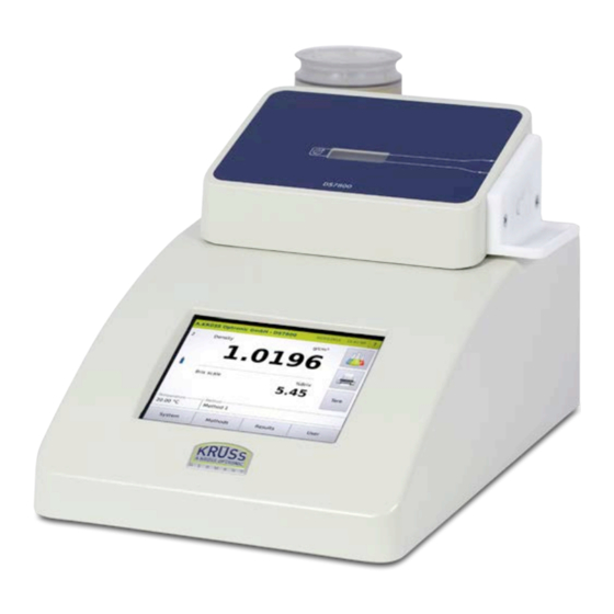
- Page 1 DENSITY METER | DS7000 SERIES USER MANUAL www.kruess.com...
-
Page 3: Table Of Contents
Inhalt Chapter 1 - Safety ......................9 1.1 Basic safety information ....................9 1.2 General sources of danger ....................9 1.3 Personnel qualifications ....................10 Chapter 2 - About this manual ..................11 2.1 Typographical conventions ..................... 11 2.2 Significance of warning messages ................... 11 Chapter 3 - Functional specification .................. - Page 4 4.10.5 User menu ....................... 31 4.11 Measuring principle ....................... 32 Chapter 5 - Basic operation ....................33 5.1 Switch menu levels ......................33 5.2 Edit settings and parameters ..................33 5.3 Save/do not save input ....................34 5.3.1 Save input ......................34 5.3.2 Do not save input .....................
- Page 5 8.1.3 Switch users...................... 59 8.1.4 Select method ....................59 8.1.5 Sample numbers ....................60 8.1.6 Measure QC sample ..................60 8.2 Present sample ......................60 8.2.1 Present sample manually ................... 60 8.2.2 Present sample semi-automatically with peristaltic pump and drying unit DS7050 ... 61 8.2.3 Present sample semi-automatically with peristaltic pump and drying unit DS7060 ...
- Page 6 9.5 Temp. tab ........................100 9.6 Settings tab ........................ 101 9.6.1 Define measurement mode ................103 9.6.2 Alarm profiles ....................104 9.6.3 Define and modify alarm profiles ..............105 9.7 Sampl. tab ......................... 108 9.7.1 Manual sample feeding ................... 109 9.7.2 Define sample feeding with DS7070 ..............
- Page 7 10.4 Network tab ....................... 155 10.5 Service tab ......................... 156 1.1.1 Access service menu ..................156 1.1.1 Service explanatory notes ................156 1.1.2 Calculate tare ....................157 7.1.1 Delete tare ..................... 159 5.1.1 Measurement calibration ................. 159 10.6 Perform firmware update ....................165 10.6.1 Run SQL script ....................
- Page 8 12.2.3 Change password ................... 195 12.2.4 Logging users in and out ................. 195 12.2.5 Edit user ......................197 12.3 Colour tab ......................... 197 12.3.1 Select colour ....................198 12.3.2 Define user-specific colour ................199 12.4 Options tab ........................ 203 Chapter 13 - Scenarios of user administration ..............205 13.1 Without operator distinction ..................
-
Page 9: Chapter 1 - Safety
Safety Chapter 1 - Safety Basic safety information h These operating instructions must be read carefully and understood prior to using the device. h These operating instructions must constantly be available on-site during the entire lifespan of the device. h All tasks may only be performed by qualified specialist staff. h All tasks must be performed with caution. -
Page 10: Personnel Qualifications
Safety Personnel qualifications Only staff who have received an induction may work with this device. -
Page 11: Chapter 2 - About This Manual
About this manual Chapter 2 - About this manual Typographical conventions Lists are bulleted: Lists • List 1 • List 2 Instructions for use Instructions that must be carried out in a particular order are numbered consecutively: 1. Step 1 2. - Page 12 About this manual Caution This warning message warns of a potentially dangerous situation which may lead to slight or moderate injury Attention! This warning message warns of damage to the device.
-
Page 13: Chapter 3 - Functional Specification
Functional specifcation Chapter 3 - Functional specification The density meters DS7000 work according to the frequency oscillator principle and are very easy to use. The density meter DS7000 can be operated as follows: • with drying unit DS7050 (for manual filling) •... -
Page 14: Areas Of Application
Functional specifcation • Direct printing on PostScript-enabled network printer possible • Complete GMP/GLP capability: Password protection, data protection, automatic hard copy or data output in CSV format • Corresponds to the relevant international standards such as Pharmacopoeia, OIML, ASTM • Calibration certificate in accordance with N.I.S.T. •... -
Page 15: Chapter 4 - Device Description
Device description Chapter 4 - Device description This chapter will deal with the following topics: • Device types • Delivery content • Device views with descriptions • Overview of the menus • Measuring principle Overview of device types Device type Devices plus optional accessories DS7000 Density meter with drying unit DS7050. -
Page 16: Device Views Ds7000
Device description Device views DS7000 4.3.1 Front view Fig. frontal view DS7000 with drying unit and peristaltic pump Drying unit DS7070 Hose connectors Peristaltic pump Touchscreen Frequency oscillator for sample in-feeding... -
Page 17: Rear View
Device description 4.3.2 Rear view Besides the mains connection and the main switch, the DS7000 has connectors for the management of the results data and a connector for the peristaltic pump. Fig. rear view of DS7000 Mains switch Fuse Network connector Network connector: Connection of a Laboratory Information and Management System (LIMS) or connection to an available network. -
Page 18: Frequency Oscillator With Connecting Pieces
Device description Frequency oscillator with connecting pieces The frequency oscillator has two connection pieces. One for the sample infeed and one for discharge. Fig. hose connections on the frequency oscillator Infeed piece Drainage piece Standards connecting pieces and acid-resistant connecting pieces are available. 4.4.1 Standard hoses and standard connection pieces Manual sample in-feeding using... -
Page 19: Acid-Resistant Hoses And Connecting Pieces
Device description Fig. standard connecting pieces for standard hoses Standard hose with Luer cone Standard connecting pieces for standard hoses 4.4.2 Acid-resistant hoses and connecting pieces Acid-resistant hoses and connecting pieces should be used for aggressive samples. Acid-resistant hoses and connecting pieces for semi-automatic sample feeding: Semi-automatic sample in- feeding Fig. -
Page 20: Peristaltic Pump Ds7070
Device description Fig. acid-resistant hoses and adapter for the Luer syringe Luer syringe PTFE hoses with UFN hollow bolt (brown) Adapter for the Luer syringe (with external thread) UFN connection pieces (with internal thread) Peristaltic pump DS7070 The peristaltic pump is connected to the density meter and transports the sample and the rinsing fluid into the frequency oscillator. -
Page 21: Drying Unit
Device description Density meter connection cable Peristaltic pump hose (TPE) UFN connection (with inner threading) for connecting to waste UFN connection (with inner threading) for connecting to the frequency oscillator Drying unit There are two different drying units: • Drying unit DS7050 •... -
Page 22: Drying Unit Ds7060
Device description 4.6.2 Drying unit DS7060 The drying unit DS7060 has two hose connections. The drying unit DS7060 has a 3/2 way butterfly valve. Thanks to the 3/2 way butterfly valve, unplugging and plugging in is not necessary for drying the frequency oscillator. The drying unit DS7060 can only be operated together with the peristaltic pump DS7070. -
Page 23: Ds7000 With Drying Unit Ds7050 Without Peristaltic Pump
Device description DS7000 with drying unit DS7050 without peristaltic pump 4.7.1 Setup Frontal view DS7000 with hose connections and without peristaltic pump Drying unit DS7050 with cartridge and silica gel Frequency oscillator for sample in-feeding Drainage piece for the waste hose Infeed piece with Luer syringe Waste hose to waste container 4.7.2... -
Page 24: Hose Connections And Flow Direction For Measurement And Rinsing
Device description 4.7.3 Hose connections and flow direction for measurement and rinsing air tube DS7050 waste tube filling tube sample/rinsing liquid waste Fig. hose connections and flow direction for measurement and rinsing 4.7.4 Hose connections and flow directions for drying DS7050 air tube waste tube... -
Page 25: Ds7000 With Drying Unit Ds7050 And Peristaltic Pump Ds7070
Device description DS7000 with drying unit DS7050 and peristaltic pump DS7070 4.8.1 Setup Fig. DS7000 with drying unit DS7050 and peristaltic pump Drying unit DS7050 with cartridge and silica gel Hose connectors Peristaltic pump DS7070 Touchscreen Frequency oscillator for sample in-feeding 4.8.2 Hoses There are four hoses for filling the sample, for rinsing and drying:... -
Page 26: Hose Connections And Flow Direction For Measurement And Rinsing
Device description 4.8.3 Hose connections and flow direction for measurement and rinsing The flow direction fundamentally depends on the pump rotation. In the following examples, the direction of rotation is counter-clockwise (to the left). air tube DS7050 drain tube waste tube filling tube sample/rinsing liquid waste... -
Page 27: Ds7000 With Drying Unit Ds7060 And Peristaltic Pump Ds7070
Device description DS7000 with drying unit DS7060 and peristaltic pump DS7070 4.9.1 Setup Fig. DS7000 with drying unit DS7060 and peristaltic pump Drying unit DS7050 with cartridge and silica gel Hose connectors Peristaltic pump DS7070 Touchscreen Frequency oscillator for sample in-feeding 4.9.2 Hoses There are four hoses for filling the sample, for rinsing and drying:... -
Page 28: Hose Connections And Flow Direction For Measurement And Rinsing
Device description 4.9.3 Hose connections and flow direction for measurement and rinsing The flow direction in the frequency oscillator depends on the pump rotation. In the following examples, the direction of rotation is counter-clockwise (to the left). connecting tube DS7060 drain tube waste tube filling tube... -
Page 29: Screen Description
Device description 4.10 Screen description 4.10.1 Main menu In this menu, measurements are taken and the result with the most important parameters is displayed. The SySTEM, METHODS, RESULTS and USER keys lead to additional submenus. The display changes depending on the device structure and settings: Position Description Displays measurement outcome with unit. -
Page 30: System Menu
Device description 4.10.2 System menu The SySTEM key opens the system menu. All device settings are defined in the system menu. See the chapter System menu. 4.10.3 Methods menu The METHODS key opens the methods menu. Methods are accessed, defined, modified, disabled and deleted in the Methods menu. -
Page 31: Results Menu
Device description 4.10.4 Results menu The OUTCOME key opens the outcome menu. The last 999 measurements are stored in the results menu along with all associated settings and parameters. Columns can be displayed or hidden and the results can be filtered, printed or exported. See the chapter Results menu. -
Page 32: Measuring Principle
Device description 4.11 Measuring principle The density measurement is carried out according to the frequency oscillator principle. Hereby a sample is filled into a swinging tube. The change in the oscillating frequency following the changed oscillation mass enables the determination of the sample’s density. The following applies: r = A x T²... -
Page 33: Chapter 5 - Basic Operation
Basic operation Chapter 5 - Basic operation The device is operated via the display using a touchscreen. Switch menu levels Operation is controlled via menus and submenus. you can access the submenus via the buttons SySTEM, METHOD, RESULTS and USER. The previous menu level can be accessed by pressing CANCEL or OK. -
Page 34: Save/Do Not Save Input
Basic operation Save/do not save input you can save changes by pressing OK or not save them by pressing CANCEL. 5.3.1 Save input OK: Saves the input provisionally, leaves the submenu and returns to the previous menu. Information All other submenus must be exited (until you reach the main menu) by pressing OK , before the input is finally saved. -
Page 35: Do Not Save Input
Basic operation 5.3.2 Do not save input Cancel: Leaves the submenu without saving the settings. Information Provisionally saved values in other submenus are not saved either! Editing authorisations The system settings may only be modified by users with administrator permissions or where necessary only by the administrator. -
Page 36: Device Version And Data
Basic operation Device version and data 1. Click on the Help symbol in the Start window. The device data shall be displayed:... -
Page 37: Chapter 6 - Installation
Installation Chapter 6 - Installation Select site Attention! Overheating damage h Do not place the device near heat sources (e.g. heating). h Do not expose the device to direct sunlight. h Ensure that air is permitted to circulate freely. Important note! Shocks and direct sunlight lead to incorrect measurement results. -
Page 38: Standard Connections For Semi-Automatic Filling
Installation 6.2.2 Standard connections for semi-automatic filling The standard filling and draining hoses have a male Luer connector (1). The hoses must be installed as follows: 1. Stick the filling hose into the infeed piece (1) 2. Stick the drain hose into the drainage piece (2) Infeed piece consisting of PTFE with female Luer connectors. -
Page 39: Acid-Resistant Hoses For Manual Filling With A Luer Syringe
Installation The hoses must be installed as follows: 1. Screw the filling hose into the infeed piece (1) 2. Screw the drain hose into the drainage piece (2) Infeed piece Drainage piece 6.2.4 Acid-resistant hoses for manual filling with a Luer syringe For working with the Luer syringe, an adapter (3) must be screwed into the infeed piece (1). -
Page 40: Install Ds7000 With Drying Unit Ds7050 And Without Peristaltic Pump
Installation Install DS7000 with drying unit DS7050 and without peristaltic pump On delivery, the drying unit mentioned in the order, including a cartridge with silica gel and the infeed and drainage pieces are already installed. Important note! If the silica gel is discoloured, it can no longer absorb any moisture and must be renewed. -
Page 41: Establish Hose Connections For Ds7050
Installation 6.4.1 Establish hose connections for DS7050 1. Connect the hoses as shown in the overview. air tube DS7050 drain tube waste tube filling tube sample/rinsing liquid waste 6.4.2 Connect peristaltic pump DS7070 1. Attach the connecting cable from the peristaltic pump to the density meter... -
Page 42: Install Ds7000 With Drying Unit Ds7060 And Peristaltic Pump
Installation Install DS7000 with drying unit DS7060 and peristaltic pump On delivery, the drying unit mentioned in the order, including a cartridge with silica gel and the infeed and drainage pieces are already installed. All that remains is for the peristaltic pump and the hoses to be connected. -
Page 43: Connect Printer
Installation Connect printer 1. Connect the printer to the serial interface (1). 2. Connect the printer’s mains cable to the power supply. 3. Configure the printer in the menuSySTEM > Tab Printer > Printer selection >Serial ASCII printer. Connect network printer To transmit the measurement results to the network printer: 1. -
Page 44: Connect The Density Meter To The Lims
Installation Connect the density meter to the LIMS your measurement results can be directly transmitted to the LIMS. 1. Connect the density meter with the LIMS using the network cable (1). 2. Configure the network connection in the menuSySTEM > Network. Connect the density meter to the mains. -
Page 45: Chapter 7 - Initial Start-Up
Initial start-up Chapter 7 - Initial start-up The density meter can be taken into operation following installation. For the initial start-up, the frequency oscillator must be thoroughly rinsed and dried. It may be necessary for the settings of the peristaltic pump to be adjusted to the length of the hoses. - Page 46 Initial start-up To dry the frequency oscillator, prepare the device as follows: Dry frequency oscillator 1. Remove the Luer syringe. 2. Connect the drying unit’s air hose to the infeed piece on the frequency oscillator. 3. Place an empty waste vessel underneath the waste hose. DS7050 air tube waste tube...
-
Page 47: Clean With Peristaltic Pump Ds7070 And Drying Unit Ds7050
Initial start-up 5. Stop drying by pressing SySTEM > Tab Functions > Air pump STOP . 6. Remove the air hose from the frequency oscillator. air tube DS7050 waste tube filling tube sample waste Now measurement of samples can begin. See the chapter System menu for how to assign functions to the keys. -
Page 48: Clean Frequency Oscillator With Individual Functions
Initial start-up 7.3.1 Clean frequency oscillator with individual functions See the chapter System menu for how to assign functions to the keys. Rinse 1. Fill a rinsing vessel with the rinsing solution or distilled water and hang the filling hose in the rinsing vessel. - Page 49 Initial start-up For the next step (drying the frequency oscillator), prepare the device as follows: 1. Connect the air hose to the draining piece on the frequency oscillator. 2. Hang the filling hose in an empty waste vessel. DS7050 air tube filling tube waste Caution...
-
Page 50: Clean Frequency Oscillator With Cleaning Procedure
Initial start-up air tube DS7050 drain tube waste tube filling tube sample waste 7.3.2 Clean frequency oscillator with cleaning procedure See the chapter Method menu > Tab Cleaning for how to define cleaning procedures. Rinse 1. Access the method with the defined cleaning procedure steps. 2. - Page 51 Initial start-up air tube DS7050 drain tube waste tube filling tube rinsing liquid waste 2. Begin the second step. The cleaning solution is pumped off. For the next, third step (drying the frequency oscillator), prepare the device as follows: 1. Disconnect the drain hose from the draining piece on the frequency oscillator. 2.
-
Page 52: Clean With Peristaltic Pump Ds7070 And Drying Unit Ds7060
Initial start-up 1. Remove the air hose from the frequency oscillator and connect the drainage hose. 2. Clean the filling hose, if needed, from the outside and hang it in the sample to be measured. air tube DS7050 drain tube waste tube filling tube sample... - Page 53 Initial start-up 3. Press SySTEM > Tab Functions > Peristaltic pump START to transport the liquid into the frequency oscillator. 4. Stop the pump by pressing SySTEM > Tab Functions > Peristaltic pump STOP if no more liquid should be sucked in. Drain 1.
- Page 54 Initial start-up 2. Press SySTEM > Tab Functions > Air pump Start. 3. Stop the air pump by pressing SySTEM > Tab Functions > Air pump STOP when the frequency oscillator is dry. The frequency oscillator should now be clean and dry. 7.4.2 Clean frequency oscillator with cleaning procedure The procedure for cleaning the frequency oscillator with drying unit DS7060 and...
- Page 55 Initial start-up DS7060 waste tube filling tube rinsing liquid waste 2. Begin the second step. The cleaning solution is pumped off. For the next, third step (drying the frequency oscillator), prepare the device as follows: 1. Hang the filling hose in an empty waste vessel. DS5060 drain tube filling tube...
-
Page 56: Check Filling Level Of The Frequency Oscillator
Initial start-up Check filling level of the frequency oscillator For semi-automatic filling of the frequency oscillator with the peristaltic pump the filling of the frequency oscillator must be checked. The speed and time of sample uptake are defined with the pumping parameters. The factory setting values for the pump are as follows: •... - Page 57 Initial start-up 2. Increase/reduce the rotation speed in small increments. 3. Save the entry by pressing OK. 4. Start a measurement with the MEASURE KEy. 5. Check whether the sample is being transported in the hose as required. 6. Repeat the process where required.
-
Page 58: Chapter 8 - Routine Operation
Routine operation Chapter 8 - Routine operation This chapter will deal with the following topics: • What must be done after the device has been switched on. • How to prepare your device. • How to prepare measurements. • How to start measuring. •... -
Page 59: Switch Users
Routine operation 8.1.3 Switch users 1. In the main menu, press USER > LOG OUT. A new user can now log in. 8.1.4 Select method 1. Press METHOD. The Method menu will open. 2. Select the method required using the selection menu. 3. -
Page 60: Sample Numbers
Routine operation How to define the method is described in the chapter Methods menu 8.1.5 Sample numbers Sample numbers are serially (from 1 to 999) assigned in general. After sample number 999, the next number is 001. 8.1.6 Measure QC sample For the measurement of the QC sample, an individual QC method should be defined and the measuring option should be activated under METHOD >... -
Page 61: Present Sample Semi-Automatically With Peristaltic Pump And Drying Unit Ds7050
Routine operation 8.2.2 Present sample semi-automatically with peristaltic pump and drying unit DS7050 1. Hang the filling hose in the sample. 2. Hang the waste hose in the waste vessel. air tube DS7050 drain tube waste tube filling tube sample waste 8.2.3 Present sample semi-automatically with peristaltic pump and drying unit DS7060... -
Page 62: Present The Sample Plate For The Auto Sampler
Routine operation 8.2.4 Present the sample plate for the auto sampler 1. Place the samples on the sample plate. 8.2.5 Begin measurement The start-up behaviour is different depending on whether temperature control is switched on or not. No temperature control! If there is no defined set temperature, there is no temperature control and the measurement can begin immediately. -
Page 63: Input Standard Value
Routine operation 1. Enter the desired text. 2. Confirm the entry by pressing OK. 8.2.7 Input standard value If the method parameter METHOD > Scale1 > Input is set to Yes, the dialog box opens for entering the standard value. 1. -
Page 64: Define Sample Series For Auto Sampler
Routine operation 8.2.8 Define sample series for auto sampler After pressing the Measure key, the dialog box opens for entry of the sample series and sample numbers. 1. Input the name of the series directly. 2. Activate Automatic to name the sample series automatically. 3. -
Page 65: Measurement
Routine operation Measurement One-shot measurements For one-shot measurements, a one-shot measurement is performed. For interval measurement, the defined number of measuring points is measured at set intervals. For interval measurement, the defined number of measuring points is measured at set Interval measurement intervals. -
Page 66: Measuring Process With Peristaltic Pump Ds7070
Routine operation The results are not saved automatically. Individual measurement results are saved by pressing the MEASURE KEy. The measurement is stopped when another method is accessed. The results are labelled in the results list under RESULT > Measurement mode: Continuous measurement. -
Page 67: Measurement Procedure With Autosampler
Routine operation Measurement procedure with Autosampler For automated sample presentation, the sample is transported into the frequency oscillator and measured after the MEASURE KEy has been pressed and the sample series entered. The sample is transported into the measurement system by means of the peristaltic pump. If the value is stable, it is saved. -
Page 68: Manually Clean Without Peristaltic Pump Ds7070
Routine operation 8.6.1 Manually clean without peristaltic pump DS7070 1. Clean the sample with a minimum of 10 ml distilled water. air tube DS7050 waste tube infeed piece rinsing liquid waste To dry the frequency oscillator, prepare the device as follows: 1. -
Page 69: Clean Semi-Automatically With Peristaltic Pump And Drying Unit Ds7050
Routine operation 8.6.2 Clean semi-automatically with peristaltic pump and drying unit DS7050 Within a measurement series the next sample is either • displaced with the previous one • rinsed with rinsing fluid 1. Wipe the filling hose and hang it in the sample to be measured next. Sample displacement air tube DS7050... -
Page 70: Clean Semi-Automatically With Peristaltic Pump And Drying Unit Ds7060
Routine operation 8.6.3 Clean semi-automatically with peristaltic pump and drying unit DS7060 Within a measurement series the next sample is either • displaced with the previous one • rinsed with rinsing fluid Drying is explained using a device with drying unit DS7050 as an example. 1. -
Page 71: Clean Frequency Oscillator With Autosampler
Routine operation Cleaning is described in detail in the chapters Initial start-up and Methods menu. 8.6.4 Clean frequency oscillator with Autosampler Between samples, the frequency oscillator is cleaned automatically as defined in the method. Cleaning is described in detail in the chapters Initial start-up and Methods menu. Autosampler operation with firmware version 7.215 and above With firmware version 7.215, the operation of the autosampler via the software has been improved and expanded. - Page 72 Routine operation This is the procedure 1. Click on the line containing the name of the sample series >-Edit description- 2. Enter the name you want to assign and confirm with OK In the Start sample series menu, you can also specify the first and last sample position to be measured.
-
Page 73: Configure Sample Series Menu
Routine operation 8.7.2 Configure sample series menu The Configure sample series menu is accessible via the Start sample series menu by pressing the OK button. The name of the sample series can be edited in the Configure sample series menu just as it is in the Start sample series menu. -
Page 74: Configure Measuring Sequence Using A Barcode Scanner
Routine operation 4. Enter the sample ID of the new row and confirm with OK In existing rows, the sample positions can not be edited. In existing rows, the sample ID can be added or edited. Only the sample ID from the selected rows are added or edited. This is the procedure 1. -
Page 75: Measure Previous Sample Series
Routine operation This makes it possible to enter the barcodes of several samples without putting the barcode scanner down. 8.7.4 Measure previous sample series It is possible to measure previous sample series. These past sample series can be restarted directly or edited and started. Previous sample series can be recalled within the Start sample series menu or in the Configure sample series menu. -
Page 76: Pause The Sample Series
Routine operation 2. Click on the line containing the name of the sample series 3. Then click on the check boxes next to the lock symbols of the previous sample series you want to protect. 8.7.6 Pause the sample series It is possible to pause an already running sample series and to edit all still to be performed measurements of the sample series. -
Page 77: Autosampler Operation With Activated Templates
Routine operation By clicking the Cancel button, the sample series is aborted and discontinued. 8.7.7 Autosampler operation with activated templates If in the currently selected method the sample feeding is set to autosampler, the autosampler is activated and templates are used, the Configure sample series menu appears directly in the main menu via the measurement button. -
Page 78: Measurement Results
Routine operation Measurement results The measured result is displayed with the unit and the sample number. 8.8.1 Result presentation If an alarm profile (METHOD > Set.) is set, the results are checked to determine whether they are within the upper and lower limits. If the results are outside the limits, they are labelled as follows: Results below the lower limit -------... -
Page 79: Export And Print Result List
Routine operation The result is printed. The key Print: Result is allocated to a key in the main menu as part of the factory settings. Automatic printing For automatic printing, the option METHOD > Opt. > Automatic print must be activated. 8.8.3 Export and print result list All measurement results shown in the result list may be exported and printed. -
Page 80: Filter Results Pane
Routine operation The selected (marked) results are printed on the connected printer. 1. Press ExPORT to export the results list. Export The selected results are exported. How result lists are printed and exported is comprehensively described in the chapter Results menu . 8.8.4 Filter results pane If you would like to filter the results pane (from-to), do the following:... -
Page 81: Final Cleaning
Routine operation 4. Save the entry by pressing OK. The list with the QC results is displayed. How to filter results is comprehensively described in the chapter Results menu. Final cleaning After the measurements are complete, the frequency oscillator must be thoroughly cleaned. -
Page 82: Chapter 9 - Methods Menu
Methods menu Chapter 9 - Methods menu The chapter Methods menu deals with the following topics: • Access methods menu • Explanation of all method parameters • Create and define new methods • Change methods • Define sample feeding • Define cleaning procedures The method parameters may be modified by users with administrator permissions. - Page 83 Methods menu Tabs/Keys Explanatory notes Scale 1 Two measurement scales can be defined. • Scale 1, the primary scale. It is shown larger in the upper area in Scale 2 the main menu. • Scale 2, the secondary scale. Where required, this can be additionally defined and is shown smaller and in the lower area in the main menu.
-
Page 84: Create New Method
Methods menu 1. Click on METHODS > EDIT to enter Edit mode. All parameters highlighted in grey may be selected and modified. Keys Explanatory notes Rename method. Opens the menu to create a new method. After a confirmation prompt, deletes the method displayed. The settings are confirmed, the method menu is closed and the start menu is opened. - Page 85 Methods menu 2. Click NEW. The input window for the name of the new method is opened. Define 3. Click on the grey key Name of the new method to be created. 4. Enter the name of the method required. method parameters To confirm the method parameters of the current method: 5.
-
Page 86: Change Method Names
Methods menu Change method names The method names can be modified at any time. 1. Select the method to be modified under Name. 2. Click on METHODS > EDIT. 3. Click on RENAME. The new name input dialog box will open. 4. - Page 87 Methods menu Scale 1 and Scale 2 Scale Selection menu of pre-defined (marked with *) and user-defined measurement scales. Density* The value actually measured in g/cm3. Relative density 20/20* Has no unit. The relative density 20/20 is calculated by dividing the density of the sample at a temperature of 20 °C by the density of pure water at a temperature of 20 °C.
-
Page 88: Define New Scale
Methods menu Temperature compensation If the results at the temperatures given always deviate by a certain amount, the results can be automatically corrected by temperature compensation. The following options are available: none There is no temperature compensation. -Manage temperature comp.- User-defined entry of temperature compensation. - Page 89 Methods menu 3. Press EDIT > NEW to define a new scale. 4. Click on the grey key and enter the name of the scale. Define new scale name To import the settings of the current scale: Define scale parameters 5.
- Page 90 Methods menu 6. Press OK to save input. The newly created scale can then be defined further. 7. Select the desired data under the tabs General,Conversion and Options. General tab In the tab General , the basic data for the scale is defined.
- Page 91 Methods menu General Based on Selection menu for: scale • none • pre-defined scales (labelled *) • defined scales The settings from the selected scale are accepted for the new scale. Unit Selection menu for: • none • pre-defined units •...
- Page 92 Methods menu Conversion None There is no conversion of measurement results. Linear The conversion factor for the calculation of measurement results is calculated in a linear fashion. A measurement value and the associated parameters are entered for this purpose: Polynomial The conversion factor for the calculation of measurement results is calculated using a polynomial.
-
Page 93: Define Calculation Formula
Methods menu Options Disable scale Activated, the defined scale is disabled. This is not available in the selection menu for the definition of Scale 1 or 2. Deactivated, the defined scale is not disabled. This is available in the selection menu for the definition of Scale 1 or 2. 9.4.2 Define calculation formula A formula cannot be defined for factory settings scales. - Page 94 Methods menu The dialog box opens: 4. Click on the grey key under Formula. The formula definition dialog box opens: 5. Enter the required formula (e.g. M/1.84). Measured value Parameters 6. Save the entry by pressing OK. The formula is saved and the subsequent measurement result is calculated with this formula.
-
Page 95: Define Temperature Compensation
Methods menu 9.4.3 Define temperature compensation A temperature compensation cannot be defined for factory settings scales (labelled *) . This is the procedure 1. Click on METHODS > Tab Scale 1 or Scale 2 > EDIT. The method menu is in edit mode. 2. - Page 96 Methods menu Define new scale name 3. Press EDIT > NEW. 4. Click on the grey key and enter the name of the temperature compensation. To confirm the current compensation settings (e.g. ICUMSA): Define 5. Activate the option Import data of the current temperature compensation. temperature compensation 6.
- Page 97 Methods menu 7. Select the conversion (Linear, Polynomial, Table or Formula) for the temperature compensation and enter the data. 8. Enter the Target temperature. 9. Confirm the entry by pressing OK. In the tab Conversion, conversion factors can be defined for the measurement results. Conversion tab Conversion Explanatory notes...
-
Page 98: Define Temperature Compensation Formula
Methods menu Formula The temperature compensation is calculated using a formula. A measurement value, the target temperature and the actual temperatures are mathematically linked for this purpose. Target temperature Target temperature input Options tab In the tab Options, the defined temperature compensation can be locked. Options Disable temperature Activated, the defined temperature compensation is... - Page 99 Methods menu The formula definition dialog box opens. 5. Enter the required formula e.g. M x 0.257x (l-Z). Measured values Target temperature Actual temperature 6. Save the entry by pressing OK. Result The formula is saved and the subsequent measurement results are calculated using this formula.
-
Page 100: Temp. Tab
Methods menu Temp. tab For devices with temperature control, the target temperature, tolerance and stabilisation time can be pre-set. In the case of temperature control, constant temperature monitoring and regulation takes place. No target temperature indicates device/room temperature. There is no temperature check. -
Page 101: Settings Tab
Methods menu Temperature control Explanatory notes Target temperature Required temperature entry. Tolerance [°C] Enter the permitted temperature difference from the required value that the measurement can be started with. Stabilisation [s] The measurement begins once the stabilisation period is complete. 1. - Page 102 Methods menu Measurement mode Explanatory notes Explanatory notes The measurement mode is used to determine the number of measurements. Labelling of measurement modes in the results memory: 0 = One-shot measurement 1 = Interval measurement 2 = Continuous measurement One-shot For One-shot measurement, one measurement value is measurement recorded.
-
Page 103: Define Measurement Mode
Methods menu -Manage alarm The alarm profile definition and editing dialog box opens. profiles- 9.6.1 Define measurement mode 1. Click on METHODS > Tab Settings> EDIT. This is the procedure The methods menu will be opened with the last method used. 2. -
Page 104: Alarm Profiles
Methods menu 9.6.2 Alarm profiles Open dialog box 1. Click on METHODS > Tab Settings> EDIT. 2. Select Alarm profiles > Manage alarm profiles. The dialog box for the definition of an alarm profile is opened. -
Page 105: Define And Modify Alarm Profiles
Methods menu General tab In the tab General , the alarm profile is defined with limit values. General tab Explanatory notes Based on scale Selection of units based on pre-defined scales. The alarm profiles can only be defined for result of Scale Scales labelled * are factory-defined. - Page 106 Methods menu 3. Click on EDIT. The dialog box is in edit mode for the modification of an existing profile or the creation of a new alarm profile. 1. In order to edit an existing alarm profile, select the alarm profile to be edited under Changing existing alarm profile Name .
- Page 107 Methods menu The alarm profile definition dialog box opens. 1. Select the scale with the required unit. Define alarm profile The alarm profiles can only be defined for the results of Scale 1. The scale must be identical to Scale 1 in the method parameters of the selected method. 2.
-
Page 108: Sampl. Tab
Methods menu 3. Save the entry by pressing OK. The alarm profile can then be selected in the method menu under tab Settings > Alarm Result profiles . If the measurement result exceeds the upper limit value of e.g. 42, the result is labelled with ++++ in the results list. -
Page 109: Manual Sample Feeding
Methods menu Sample feeding Explanatory notes Explanatory notes manual Manual sample feeding with Luer syringe. DS7070 Peristaltic pump for semi-automatic filling and cleaning. Autosampler Autosampler for fully automatic filling and cleaning. Our autosamplers AS80 and AS90 are supported. Keys The settings are accepted, the method menu is closed and the start menu opens. - Page 110 Methods menu • Direction of rotation clockwise The pumping time and revolution speed should only be modified where required (e.g. for very viscous samples). The pre-defined factory settings are found under: • METHODS > Method x > Tab Sampl. for sample feeding. Where required, these settings can be modified.
-
Page 111: Define Sample Feeding With Autosampler
Methods menu Parameters/keys Explanatory notes The settings are accepted, the method menu is closed and the start menu opens. The method menu closes without saving the entry and the start menu opens. Deletes the current method. Creates a new method. 9.7.3 Define sample feeding with autosampler. -
Page 112: Define Intermediate Cleaning For Autosampler
Methods menu Parameters/keys Explanatory notes Explanatory notes The following two parameters (Sampler mode and Interim cleaning procedure) define the procedure after sample measurement. Sampler mode Selection menu: • Displacement: The sample is sucked in and pumped off after measurement. The next sample then replaces the old sample. - Page 113 Methods menu 2. Select -Manage cleaning procedure- and press EDIT. 3. Press NEW to create a new cleaning procedure. 4. Enter the name of the cleaning procedure AS80 intermediate rinsing and drying and save it by pressing OK. The cleaning procedure AS80 intermediate rinsing and drying can then be composed using individual modules.
- Page 114 Methods menu Step 1: The cleaning procedure should begin by sucking in the cleaning solution. The next step should then be carried out automatically. Sampler: Rinse 1. Under Module type, select the module Sampler: Rinse. 2. Enter for Time30 s, Rotation anticlockwise, rpm 50. 3.
- Page 115 Methods menu 4. Confirm the entry by pressing OK. After the pause, the cleaning solution should be rinsed out of the frequency oscillator with Step 3: Sampler: rinse water and sucked empty. 1. Press ADD. 2. Under Module type, select the module Sampler: Rinse. 3.
-
Page 116: Cleaning Tab
Methods menu 4. Confirm the entry by pressing OK. 1. Once the cleaning procedure is defined, press OK. Save cleaning procedure The dialog box is closed and the cleaning procedure is then available for selection in the menu METHOD > Tab Sampl. > Intermediate cleaning procedure . Cleaning tab Cleaning procedures under METHODS >... -
Page 117: Cleaning Procedure Modules
Methods menu Open dialog box 1. Click on METHODS > Tab Cleaning > EDIT. Parameters Explanatory notes Explanatory notes Cleaning procedure Selection menu: • none • already defined cleaning procedures and factory-defined. • -Manage cleaning procedure- to define cleaning procedures. Keys The settings are accepted, the method menu is closed and the start menu opens. - Page 118 Methods menu Modules/steps Explanatory notes Autosampler: Rinse For the rinsing of the measurement cell with the autosampler, the following must be defined: • Time [s] • Direction of rotation (clockwise/anticlockwise) • Revolution speed [1/m] This module sucks rinsing fluid into the frequency oscillator. •...
-
Page 119: Define Cleaning Procedure For Ds7070
Methods menu 9.8.2 Define cleaning procedure for DS7070 How to define a cleaning procedure is described in the following example. Final cleaning with the peristaltic pump DS7070 is composed of the following steps and Example Example defined: • Step 1: Peristaltic pump, to draw water into the frequency oscillator: time 30 s, anticlockwise rotation, rpm 50, continues automatically •... - Page 120 Methods menu 4. Press NEW to create a new cleaning procedure. 5. Enter the name of the cleaning procedure (e.g. Final cleaning) and save the name by pressing OK. The cleaning procedure Final cleaning can then be composed using individual modules. Compose modules 1.
- Page 121 Methods menu The cleaning procedure should begin by sucking in the cleaning solution. The next step should then be carried out automatically. Step 1: Peristaltic pump 1. Press ADD. 2. Under Module type, select the module Peristaltic pump. connection 3. Enter for Time30 s, Rotation anticlockwise, rpm 50. 4.
- Page 122 Methods menu 3. Enter Time10s for the pause. 4. Deactivate Auto-confirmation, in order to remove the hose from the rinsing vessel before pumping off the cleaning solution. 5. Confirm the entry by pressing OK. The liquid should be pumped off after the pause. Auto-confirmation is then activated or Step 3: Peristaltic pump deactivated depending on whether the drying unit DS7050 or DS7060 is in use.
- Page 123 Methods menu 4. Deactivate Auto-confirmation, in order that the cleaning procedure stops after 30 s and can only continue with your confirmation. 5. Confirm the entry by pressing OK. Once the cleaning solution has been sucked up, the frequency oscillator should be dried. Step 4: Dry 1.
-
Page 124: Define Cleaning Procedure For The Autosampler
Methods menu 9.8.3 Define cleaning procedure for the autosampler The final cleaning of the autosampler should include the following steps: Example • Step 1: Sampler: Rinse, to draw cleaning fluid into the flow cell: Time 30 s, anticlockwise rotation, rpm 50, automatically continues •... - Page 125 Methods menu 3. Press NEW to create a new cleaning procedure. 4. Enter the name of the cleaning procedure (e.g. AS80 final cleaning) and save it by pressing OK. The cleaning procedure AS80 final cleaning can then be assembled out of individual modules.
- Page 126 Methods menu 3. Enter for Time30 s, Rotation anticlockwise, rpm 50. 4. Activate Auto-confirmation to begin the next step automatically. 5. Confirm the entry by pressing OK. The cleaning solution should soak in for 10 s. The next cleaning procedure should then Step 2: Pause be carried out automatically.
- Page 127 Methods menu 3. Enter for Time30 s, Rotation anticlockwise, rpm 50. 4. Activate Auto-confirmation, in order for drying to occur automatically after rinsing. 5. Confirm the entry by pressing OK. Once it has been rinsed, the frequency oscillator should be dried and then the next step Step 4: Dry (test measurement) should begin automatically.
- Page 128 Methods menu 3. Select Step 4: Dry, to dry the frequency oscillator again. 4. Deactivate Auto-confirmation to stop the cleaning procedure. 5. Confirm the entry by pressing OK. 1. Once the cleaning procedure is defined, press OK. Save cleaning procedure The dialog box closes.
-
Page 129: Change Cleaning Procedures
Methods menu 9.8.4 Change cleaning procedures 1. Press METHOD > Tab Cleaning > EDIT. This is the procedure 2. Select -Manage cleaning procedure-. 3. Under Name, select the cleaning procedure (e.g. Standard final cleaning) to be modified. - Page 130 Methods menu 4. Press EDIT to change the selected cleaning procedure. 5. Select the module to be modified. 6. The module can be modified under EDIT. 7. With ADD you can add further modules to the cleaning procedure...
-
Page 131: Opt. Tab
Methods menu Opt. tab In Opt. tab, the following additional measurement functions can be activated and/or deactivated: • Comment • Quality control • Automatic printing • Interval measurement with pause • Lock method 1. Click on METHODS > Tab Opt. > EDIT. Open dialog box The measuring options are displayed: Measurement... -
Page 132: Measure Quality Controls
Methods menu Measurement Explanatory notes Explanatory notes options Interval For selected interval measurement, individual measurements measurement can are begun with the Measure key. pause Lock method The active method can be disabled. Activated, the current method is disabled and cannot be used for measurements. - Page 133 Methods menu 6. Click on the Tab Opt. > EDIT 7. Activate Quality control. 8. Confirm entries by pressing OK. 1. Access QC method 1. Measure QC samples 2. Start the measurement with the MEASURE KEy. The results will be labelled in the result list with QC in the QC column. Result...
- Page 134 Methods menu QC samples can then be filtered for printing and exporting. How to filter QC results is described in the chapter Results menu filter QC sample.
-
Page 135: Disable/Release Methods
Methods menu 9.9.2 Disable/release methods Objective you can disable/release access for any method. 1. Click on METHODS > Tab Opt. > EDIT. This is the procedure The measuring options are displayed. 2. Activate and/or deactivate the option Disable method. 3. Save the settings by pressing OK. Result The method is/is not available in the selection menu METHOD >... -
Page 136: Select Final Cleaning
Methods menu With factory setting values, complete filling of the frequency oscillator is usually guaranteed. The pumping time and revolution speed should only be modified where required (e.g. for very viscous samples). 9.10.2 Select final cleaning Once a measurement series is complete or before decommissioning, a final cleaning should be performed. -
Page 137: Configure Autosampler
Methods menu 1. Access the method with intermediate cleaning selected under Tab Cleaning. 2. Start the cleaning via SERVICE > Tab Functions > Function Cleaning. The cleaning selected in the method will be performed. 9.11 Configure autosampler To work with the autosampler, the sample uptake, type of sample uptake, intermediate cleaning and final cleaning must be defined. -
Page 138: Method: Select Final Cleaning
Methods menu 9.11.4 Method: Select final cleaning 1. Access the required method via METHOD. 2. Select under METHOD > Tab Cleaning > EDIT. 3. Select the required final cleaning under Cleaning procedure . There are pre-defined factory-set cleaning procedures for final cleaning. 9.11.5 Start final cleaning Final cleaning is begun as follows:... -
Page 139: Chapter 10 - System Menu
System menu Chapter 10 - System menu All device settings are adjusted in the system menu. The system settings can be defined for all users or user-specifically. 10.1 General tab The general settings are: • Date and time • Date format •... -
Page 140: Explanatory Notes
System menu The fields for editing are now in Edit mode. 3. Choose the required settings and save the selection by pressingOK. 10.1.2 Explanatory notes Settings Explanatory notes Date and time Date and time selection menu (global setting) Date format The required date format is selected via a selection list. -
Page 141: Set Date
System menu 10.1.3 Set date 1. Click SySTEM > EDIT > Date. This is the procedure The date selection calendar opens. 2. Click on the current date. 3. Save the selection by pressing OK. 10.1.4 Set time This is the procedure 1. -
Page 142: Printer Tab
System menu 10.2 Printer tab The printers are: • Serial ASCII printer • Network printer • PDF file All printer settings may only be modified by users with administrator permissions. Permission The printer settings may be global or user-defined. For user-specific settings, the option Activate user administration and Individual system settings must be activated under SySTEM >... - Page 143 System menu 3. Select the relevant settings using the selection lists and save the selection by pressing Serial ASCII printer An ASCII printer of your choice can be connected to the serial interface. Baud rate 2400/4800/9600/19200/38400/57600/115200 Data bits Stop bits Parity None/odd/even Xon / Xoff...
-
Page 144: Define Network Printer
System menu 10.2.3 Define network printer 1. Press SySTEM > Tab Printer > EDIT. This is the procedure 2. Select from Printer selection > Network printer. 3. Select the relevant settings using the selection lists and save the selection by pressing Network printer The data is printed out via the network printer. -
Page 145: Define Pdf File
System menu 10.2.4 Define PDF file 1. Press SySTEM > Tab Printer > EDIT. This is the procedure 2. Select from Printer selection > PDF file. 3. Select the relevant settings using the selection lists and save the selection by pressing PDF file The data is filed in a PDF file on printing. -
Page 146: Add Logo For Print-Out
System menu The settings are accepted, the system menu is closed and the start menu opens. The system menu closes without saving the input and the start menu opens. 10.2.5 Add logo for print-out Conditions Only in Printer selection: PDF file/Network printer This is the procedure 1. -
Page 147: Functions Tab
System menu 10.3 Functions tab Device functions are accessed in the Functions tab. Before these functions can be defined and/or used, they must be assigned to keys. There are 2 keys in the main menu and 6 keys in the function menu for this allocation. The keys in the function menu can be allocated once and the keys in the main menu may be allocated multiple times. -
Page 148: Access Function Menu
System menu 10.3.1 Access function menu 1. Press SySTEM > Tab Functions > EDIT. This is the procedure The available functions may be found in selection mode. 10.3.2 Available functions Available functions Explanatory notes Logs the user off. User: Log off Tare For the calculation of an offset (tare) which is then automatically included in the result calculation. -
Page 149: Assign Function Keys
System menu Available functions Explanatory notes Print: Result details The function triggers printing of the result details. Scales: Manage Opens the Scales submenu for editing scales. Methods: Cleaning Opens the method menu for the selection of pre-defined cleaning procedures. New cleaning procedures can be defined via -Manage cleaning proc-. -
Page 150: Allocate Function Keys Multiple Ways
System menu If you would not like to assign the selected function to any key, click in the grey field next to the small selection window. The small selection window closes. 3. To assign the function Cleaning to a key, click on ASSIGN. The key selection window in the function window and in the main screen will open. - Page 151 System menu This is the procedure 1. Press SySTEM > Tab Functions > EDIT. 2. Select Cleaning. The following selection window opens: 3. To assign a function to a key, click on ASSIGN. 4. Select the option Assign in the next window and click on the key to be overwritten RESULT.
- Page 152 System menu Multiple allocation of the selected key. REPLACE Overwrite the selected key. 5. Click on the required option (ADD/REPLACE). 6. Save the selection by pressing OK. Results for ADDITION > Multiple allocation: Result of multiple allocation Result of key replacement Results for REPLACE >...
-
Page 153: Delete Key Function
System menu 10.3.5 Delete key function The function of a user-defined key can be deleted. Objective This is the procedure 1. Press SySTEM > Tab Functions > EDIT. The function menu opens in edit mode: 2. Select the function to be deleted, e.g. cleaning. A small selection window opens: 3. - Page 154 System menu 5. Confirm the entry by pressing OK. The function Cleaning on the key is deleted. Result...
-
Page 155: Network Tab
System menu 10.4 Network tab The following network settings are possible: • IP address • DHCP client • Subnet mask • Gateway • LIMS device name The network settings may only be modified by users with administrator permissions. Permission This is the procedure 1. -
Page 156: Service Tab
System menu 10.5 Service tab In the Service tab, the following functions can be performed: • Tare • Measurement calibration • Firmware update • Run SQL script • Remote monitoring Device settings and functions may only be modified by users with administrator Permission permissions. -
Page 157: Calculate Tare
System menu Parameters Explanatory notes Measurement calibration The density meter is calibrated using the measurement calibration. A measurement calibration is carried out in order to enable correct measurements and to remove systemic measurement deviations. For measurement calibration, two measurements are taken: First measuring point: empty sample space (air) Second measuring point: Water (degassed) - Page 158 System menu 2. Enter the sample control value in g/cm³ and the number of measurements. 3. Fill the sample into the frequency oscillator. 4. Press MEASURE. The measurements are carried out and the tare offset is calculated and displayed. 5. Save the value by pressing SAVE. The result is saved provisionally with the date and time.
-
Page 159: Delete Tare
System menu 6. Press OK to save the value permanently. A previously saved tare value will be overwritten. 7. Press CANCEL if the result should not be saved. The previously saved blank value is then retained. Result This tare value is taken into account in the calculation for all measurement results. 7.1.1 Delete tare An existing tare value can be deleted. - Page 160 System menu Temperature display The measured temperature lies above the target temperature. Blue The measured temperature lies below the target temperature. Measured temperature = target temperature. This is the procedure 1. Press SySTEM > Tab Service > EDIT >Measurement calibration. The dialog box for measurement calibration opens: Keys Explanatory notes...
- Page 161 System menu Keys Explanatory notes Cancels the process and closes the window. Measure air 1. Clean the frequency oscillator very carefully. 2. Select Air in the dialog window. 3. Press NExT, to start the air calibration . First, the frequency oscillator is dried and tempered. 4.
- Page 162 System menu The air value is measured and the result is displayed. 6. Press SAVE, to apply the measurement values.
- Page 163 System menu 1. Fill water into the frequency oscillator. Measure water Important! The water must be free of air bubbles to ensure a correct measurement. 2. Click Measurement calibration CALIBRATION POINT WATER MISSING is displayed on the button, for as long no water value is present.
- Page 164 System menu 7. Apply the values with SAVE. 8. Apply the values permanently using OK. Result The density meter is calibrated.
-
Page 165: Perform Firmware Update
System menu 10.6 Perform firmware update The new device software is sent to you by email. Condition This is the procedure 1. Set up the “update” directory on your USB stick. 2. Add the files sent to you by email to the “update” directory. Save result data! The database can be overwritten during an update. -
Page 166: Run Sql Script
System menu 7. Select firmware updates. 8. Begin the firmware update by pressing START. The firmware update will be performed. Do not switch off device! During the update, the device has no functional program to restart. h Do NOT turn off the device during the firmware update! 9. - Page 167 System menu 2. Click NExT or the tab Select script. If you would like the script run to be recorded in a log file on the USB stick: 3. Activate Logfile [x] Run script 4. Connect the USB stick with the SQL script to the device. 5.
-
Page 168: Opt. Tab
System menu 10.7 Opt. tab The following functions can be activated in the Opt. tab: • Activate user administration • Individual system settings • User-defined colours • Enter profile without password • Activate xML file interface The system options may only be modified by users with administrator permissions. Permission This is the procedure 1. -
Page 169: Activate User Administration
System menu System options Explanatory notes Activate XML file interface activated deactivated. The settings are accepted, the system menu is closed and the start menu opens. The system menu closes without saving the input and the start menu opens. 1.1.1 Activate user administration User administration can be activated and/or deactivated. - Page 170 System menu 3. Activate Individual system settings. A dialog box opens asking if you would like to continue: 4. Press yES if you would like to activate the Individual system settings. Result The User profile changes from the user General to the logged-in user (for example, the administrator).
-
Page 171: Audit Trail
System menu 10.8 Audit Trail The audit trail is available since firmware version 7.214. The device contains an audit trail function. This function offers a computer-generated and timestamped recording off all changes which are relevant for the measurement or the system when using the device. -
Page 172: Opening The Audit Traillog
System menu 10.8.2 Opening the audit traillog To access the audit trail log the window for the device information has to be selected. Only users with administrator rights have access to the audit trail log. This is the procedure 1. Press the icon ? within the start screen > Audit-Trail-Log. 10.8.3 Recorded content Each entry of the audit trail saves ten specific values. -
Page 173: Functionality Of The Entry Creation
System menu Value Meaning Comment An annotation about the setting changes entered by the user. Available only if the commentary feature is enabled in the system options. User The name of the user who was logged in and made the change. -
Page 174: Printing Or Exporting The Audit Trail Log
System menu 10.8.5 Printing or exporting the audit trail log If a printer is configured (network or PDF file), the audit trail log can be printed or exported. Printing or exporting the audit trail log will always result in a complete audit trail log. -
Page 175: Chapter 11 - Results Menu
Results menu Chapter 11 - Results menu All measured values are saved in the results list. The user can select what appears in this results list. The list can be exported and printed completely or in filtered form. Filters can be user-defined and saved. This chapter deals with the following topics: •... -
Page 176: Access Result Details
Results menu 11.2 Access result details The details of a measurement result, one-shot measurement results and the corresponding raw values and statistics are accessed as follows. This is the procedure 1. Press RESULTS. 2. Double-click on the required result row. 3. - Page 177 Results menu Display statistics 5. Click on Statistics tab.
-
Page 178: Create Results List
Results menu 11.3 Create results list 11.3.1 Sort results list in descending or ascending order This is the procedure 1. Press RESULTS > FILTER. The filter menu will open. 2. Click under Sort on the key LAST RESULT AT START or LAST RESULT AT END. The results will be listed in the desired order. -
Page 179: Filter Results According To Time Period
Results menu 3. Use the arrow key to move the marked field into the Selected fields pane. 4. Save the selection by pressing OK. Result The target temperature will be displayed in the results list. Display/keys Explanatory notes Available fields Displayed here are the remaining available fields which were not selected for the output. -
Page 180: Reset Time Period
Results menu 3. Click on START VALUE. All results from this start value are displayed. 4. Double-click on the last result to be shown. 5. In the selection window, click END VALUE. Result The results in the selected area are displayed. The displayed results can then be printed using PRINT and exported using ExPORT 11.4.2 Reset time period... -
Page 181: Filter Menu Functions
Results menu 11.5.2 Filter menu functions Display/keys Explanatory notes Sort Sorts results according to date in ascending or descending order. Display Selection of data columns for result output. Displays the active filter. The filter must be previously defined for Active filter this display. -
Page 182: Define And Save Filter
Results menu 2. Select the required filters using the keys or Additional filters . Under ADDITIONAL FILTERS..., all defined filters are displayed via the selection menu: 3. Click on the required filter and confirm the selection by pressing OK. Result The filter is loaded and active. - Page 183 Results menu 2. To define a new filter, press EDIT > NEW. The dialog box Create new results filter opens: 3. Enter the filter name under Name of the new results filter to be created . 4. Tick the box if you would like to Accept current filter adjustment. 5.
- Page 184 Results menu 6. Click on the required tabs and select the options. Explanatory notes Date+Time Filter results according to date and time. User+Method+Text Filter results according to user, method and comment text. Additional filters Filter quality controls and last sample series. 7.
-
Page 185: Filter According To Date And Time
Results menu 11.6.3 Filter according to date and time The results are to be displayed for a certain time period or date. 1. Press RESULTS > FILTER > ADDITIONAL FILTERS... This is the procedure 2. Click on the tab Date + Time. 3. -
Page 186: Filter Qc Samples
Results menu 4. Select the required User, Method and/or Text in comment field. 5. Confirm the selection by pressing OK. 11.6.5 Filter QC samples Only QC results should be displayed. Conditions In order to be able to filter QC results, quality control must be activated under METHODS >... -
Page 187: Filter Last Sample Series
Results menu 11.6.6 Filter last sample series The results in the last measured sample series can be displayed as follows. 1. Press RESULTS > FILTER > ADDITIONAL FILTERS... This is the procedure 2. Click on the tab Additional filters. 3. Click on EDIT. 4. - Page 188 Results menu 2. Click on ADDITIONAL FILTERS... > EDIT. The dialog box Edit data filter opens: 3. Select the filter to be modified under Name. 4. Click on the tabs and select the required options. 5. Save the entry by pressing OK. The filter is modified and saved.
-
Page 189: Reset Existing Filter
Results menu 11.6.8 Reset existing filter An active filter can be reset at any time without the filter being deleted from the filter list. 1. Press RESULTS > FILTER. This is the procedure The filter selection dialog box opens. 2. Click on RESET FILTER. Result The active filter is reset and all of the results in the result list are displayed again. -
Page 190: Print Results
Results menu 11.8 Print results Only marked results are printed. This is the procedure 1. Press RESULTS. 2. If required, filter the results to be printed. 3. Mark the results to be printed. 4. Press PRINT. If you have not marked any results, the following dialog window opens: 5. -
Page 191: Chapter 12 - User Menu
User menu Chapter 12 - User menu Use administration allows user-specific device operation. Depending on the user settings, the user can log in with or without a password. Permission All user settings may only be modified by users with administrator permissions. Users can only be defined if underSySTEM >... -
Page 192: General Tab
User menu Settings Explanatory notes Options User options for the selected user: • Block user • Block after 3 login attempts • Reset password Keys Exports user settings. Prints user settings on the configured printer. The settings are accepted, the user menu is closed and the start menu opens. -
Page 193: Create New User
User menu Login Shows the name of the current user. The name can be changed using the key. The key opens the input window for a new login name. Valid until Selection window: unlimited/establish date of validity. unlimited Validity unlimited. Establish date If the permissions are intended to be valid only for a limited period, a... - Page 194 User menu 3. Enter the user nameand login name. The following info window is displayed: 4. Confirm the defined user by pressing OK. The user is created. 5. Click on Permission and select Permission (User or Administrator). 6. Click on Valid until.
-
Page 195: Log In With Or Without Password
User menu 7. Select either unlimited or enter the duration of validity. 8. Confirm entries by pressing OK. The user is completely defined. 12.2.2 Log in with or without password The password is entered by the user themselves when they first log in. If a user profile is to be able to work with the device without entering a password, the following option must be activated: SySTEM >... - Page 196 User menu On the first login, the user is asked to define a password: 1. Press OK. 2. Enter your personal password. For security, the password must be entered again. The password is saved. The user name and password are then requested when logging in on subsequent occasions.
-
Page 197: Edit User
User menu 12.2.5 Edit user Condition The user can only be edited by the administration. This is the procedure 1. Press USER > Tab General. 2. Under Name , select the user to be edited and press EDIT. The dialog box for user settings can be found in Edit mode. 3. -
Page 198: Select Colour
User menu Colour tab Colour scheme Selection menu for: • factory-defined colour schemes (labelled with *) • user-defined colour schemes • -Manage colour schemes- : define and change user- defined colour schemes Background Displays the background colour of the selected colour scheme. -
Page 199: Define User-Specific Colour
User menu 2. Select one of the pre-defined Colour schemes. 3. Save the selection by pressing OK. The selected colour scheme is set. 12.3.2 Define user-specific colour In order for the user-defined colours to be used, they must be activated under SySTEM >... - Page 200 User menu 3. Press EDIT > NEW. The new colour name definition dialog box will open. 4. Enter the name of the new colour scheme and confirm input by pressing OK. 5. If desired, activate Copy current colour scheme if you would like to adopt the colour setting of the current colour scheme.
- Page 201 User menu Background tab 1. Click on the tab Background to define the background. The background colour can be selected as follows: • directly via the keys Red, Green, Blue • By entering the Colour code • via the key Current background colour 2.
- Page 202 User menu 2. For the text, enter the RGB colours (Red, Green, Blue) or Colour code. 3. Save the settings by pressing OK. Options tab 1. Click on the tab Options to lock or release the new colour scheme. 2. To lock the function, activate Lock colour scheme 3.
-
Page 203: Options Tab
User menu 12.4 Options tab Under the tab Options, you can lock a user and reset the password. Open dialog box 1. Press USER >Tab Options > EDIT. The menu opens:... - Page 204 User menu User options Explanatory notes Block user activated. The selected user is blocked and has no access to the device. This option can be activated by users with administrator rights or is activated automatically if the user enters the incorrect login details 3 times.
-
Page 205: Chapter 13 - Scenarios Of User Administration
Scenarios of user administration Chapter 13 - Scenarios of user administration With the firmware version 7.214, the user administration has been extended, which makes it possible to log in via different access authorisations. These different options are described in more detail in the following scenarios. The term operator distinction refers in the following to the distinction of the human users of the device and not to the user accounts. -
Page 206: Without Operator Distinction, But With Protected Configurations And Access Protection
Scenarios of user administration Each time the device is restarted, the user with the automatic login is logged in directly and the device is ready for use. Automatic login can not be enabled for users with administrator rights. To make system settings in this scenario, first log off the user, and then log in with a user with administrator rights. -
Page 207: With Operator Distinction
Scenarios of user administration 13.4 With operator distinction If every user of the system should have their own access, the user administration must be activated and in addition no user must have the automatic login activated. Users without the automatic login must have a password. If this was not assigned when creating the user, the password must be created when the user logs in for the first time. -
Page 208: Chapter 14 - Maintenance And Care
Maintenance and care Chapter 14 - Maintenance and care This chapter deals with the following topics: • What must be done daily/weekly • Change the fuse • Replace silica gel • Maintenance performed by Service 14.1 Maintenance and care plan When What daily... -
Page 209: Change The Silica Gel
Maintenance and care 14.3 Change the silica gel If the silica gel is discoloured, it can no longer absorb moisture and must be renewed. 1. Twist off the cartridge. 2. Fill the cartridge with silica gel. 3. Place the cartridge onto the drying unit and screw it on tight. 14.4 Maintenance performed by Service The density meter DS7000 does not require any regular maintenance performed... -
Page 210: Chapter 15 - Troubleshooting Table
Troubleshooting table Chapter 15 - Troubleshooting table This chapter should help you to quickly remove any errors which arise. Error Possible causes Resolution False measurements Contaminated frequency oscillator. Clean the frequency oscillator. The frequency oscillator is too moist • Drying the measurement chamber and dilutes the sample. -
Page 211: Chapter 16 - Transport, Storage And Disposal
Transport, storage and disposal Chapter 16 - Transport, storage and disposal 16.1 Transport For transport, please be aware of the following: h Please only use the original packaging for transport, including the plastic mouldings. h Please only transport at an ambient temperature of -20 to +60 °C and max. 95% humidity. -
Page 212: Chapter 17 - Appendix
Appendix Chapter 17 - Appendix 17.1 Glossary NIST National Institute of Standards and Technology Good Laboratory Practice (quality assurance system) LIMS Laboratory Information Management System Food and Drug Administration ICUMSA International Commission for Uniform Methods of Sugar Analysis 17.2 Technical specifications Designation Specifications Measurement range... -
Page 213: Order Information
Appendix 17.3 Order information Parts description Description Order No. Density meter 17.4 Warranty provisions A.KRÜSS Optronic provides the warranty for materials and manufacturing of the digital polarimeter family for a period of 24 months from the date of delivery. During this warranty period, A.KRÜSS Optronic will deal with defects through repairs or exchange, if these fall within the warranty claim. - Page 214 A.KRÜSS Optronic GmbH Alsterdorfer Straße 276–278 22297 Hamburg | Germany +49 40 514317-0 +49 40 514317-60 E-Mail info@kruess.com www.kruess.com...
Need help?
Do you have a question about the DS7000 Series and is the answer not in the manual?
Questions and answers