
Related Manuals for kruss DSA100


Summary of Contents for kruss DSA100
- Page 1 Drop Shape Analyzer DSA100 Installation and Operation V1-45 © KRÜSS GmbH, Hamburg 2004-2014...
-
Page 3: Table Of Contents
Comprehensiveness of the printed version and the electronic manual....... 7 Note concerning images ........................7 Technical customer service ........................7 2 Introduction ..........................8 3 DSA100 overview........................10 4 Computer system ........................11 Mounting an IEEE-1394 interface board ..................11 Driver installation ........................... 12 4.2.1... - Page 4 7.7.10 Mounting the ST13 miniature sample table (optional) ............ 53 8 Manual single-dosing unit DS3200/3201 ..............55 Fitting a disposable syringe ....................... 55 Assembling the dosing unit to the DSA100................. 56 Adjusting the dosing unit ........................57 9 Software-controlled single-Dosing unit DS3210 ............58 Mounting the dosing unit ........................
- Page 5 11.3 Construction ............................. 69 11.3.1 Front - controls ..........................69 11.3.2 Rear - connectors ..........................69 11.4 TC30/40: Mounting on the DSA100 ....................70 11.5 Connectors and connections ......................70 11.5.1 Connecting the thermostat ......................70 11.5.2 Condensation protection ......................71 11.5.3 External temperature sensor .......................
- Page 6 page 4 Contents 12.5.2 Power supply / Communication ....................85 12.6 Filling / Filling level ..........................85 12.7 Fitting the temperature sensor ......................86 12.8 Covering the needle inlet ........................86 Appendix ............................87 I Computer requirements ...................... 87 II Exchanging cameras ......................90 IIa) Assembly ..............................
-
Page 7: General Information
SPA C SPA C SPAC SPAC Disconnect the DSA100 from the power supply immediately if there is any damage to the electronics, if liquids are spilled over the DSA100 or if there is an escape of tempering medium. SPA C SPA C SPAC SPAC Handle all glass parts and optical parts with care. -
Page 8: Procedure If Repairs Should Be Necessary
page 6 General information Procedure if repairs should be necessary Contact KRÜSS Contact KRÜSS customer support. If you did not obtain the measuring instrument directly from KRÜSS but from a dealer, please contact your dealer first. He may be able to rectify the damage. -
Page 9: Comprehensiveness Of The Printed Version And The Electronic Manual
SPA C SPA C SPAC SPAC Note concerning images The images of some components show the mounting procedure and use for a KRÜSS instrument DSA30. The procedure for the DSA100 is identical in these cases. SPA C SPA C SPAC SPAC Technical customer service If problems should occur when working with your KRÜSS product please consult... -
Page 10: Introduction
PC-control of all the components. Possible uses of the DSA100 The DSA100 measuring system – depending on the hardware and software supplied – opens up the following possibilities: Contact angle measurements on drops of liquid in a gaseous or liquid phase ... - Page 11 Introduction page 9 Integrated and extendable databases with substance data on liquids that can be directly linked to the measuring data Comfortable data management and documentation Extendable at any time with components such as environmental chambers, automatic axes, software-controlled optics or multiple dosing units with up to 8 syringes...
-
Page 12: Dsa100 Overview
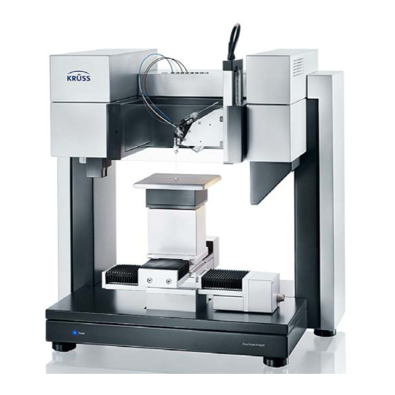
DSA100 overview DSA100 overview In order to measure the contact angle with the DSA100 a drop is placed on a sample located on a moveable sample table. The drop is illuminated from one side and a camera at the opposite side records an image of the drop. -
Page 13: Computer System
Computer system page 11 Computer system If you have purchased your computer from KRÜSS together with the DSA100 and if the frame grabber board or IEEE-1394 interface board has already been installed then you can skip this chapter. For system requirements for the computer please read appendix I. -
Page 14: Driver Installation
page 12 Computer system Driver installation SPA C SPA C SPAC SPAC 4.2.1 Safety measures for driver installation CAUTION Damage due to improper driver installation Under Windows XP and Vista, the frame grabber board can be damaged if the automatic driver update via internet is activated. ... -
Page 15: Frame Grabber Driver For Cf3200/3201
Computer system page 13 3. Select the option Never search Windows Update for drivers and click on OK. … Later, when the installation process is finished, the option Ask me to search can be selected if this Microsoft service is desired. However, we do not recommend the first option without asking SPA C SPA C SPAC SPAC... - Page 16 page 14 Computer system CAUTION Damage due to improper driver installation If the Mil-Lite patch is not installed the frame grabber board can be damaged. Carry out the installation in exact accordance with the following instructions. Step 1: Installation of the software PFRemote. ...
- Page 17 Computer system page 15 6. Confirm the installation of the two components PFRemote with the option Without USB Environment. 7. Confirm the proposed start menu folder with Next or select a custom-defined ’ folder with Browse. With t create the creation of a start menu item can be obviated.
- Page 18 page 16 Computer system 4. Set a tick to the box for the Solios board and confirm with Next. 5. Leave the default settings on the following page unchanged and confirm with Next. 6. Confirm your license agreement and click on Next. Ignore the possible warning that the Windows Logo Test was not passed and continue with the installation.
- Page 19 Computer system page 17 Step 4: Firmware check / frame grabber update If a frame grabber update is necessary (see subsequent instructions), this step must not be omitted. The frame grabber can be damaged when working with a dated firmware. 1.
-
Page 20: Ieee 1394 Driver For Cf31/3216
page 18 Computer system 4.2.4 IEEE 1394 driver for CF31/3216 The IEEE 1394 driver should be installed before installing the DSA1/DSA3/DSA4 Software under all circumstances. 1. Insert the DSA1/DSA3/DSA4 CD. 2. Open the folder SUPPORT CFxx1x AxF AVT IEEE1394. Open the containing ... - Page 21 Computer system page 19 5. Installation options Location: Confirm proposed installation folder with Next (recommended) or choose a different folder using Browse. Create shortcuts: Determine if shortcuts for AVT software to be installed shall be created on the desktop. Install startmenu items: Determine if AVT items in the Windows start menu ...
- Page 22 page 20 Computer system 8. A Microsoft driver is displayed in the Driver Installer. Select the option Intek 1334 Bus Driver in the hidden drop-down menu in the column Switch Click on Apply. SPA C SPA C SPAC SPAC...
-
Page 23: Setting Up
Do not transport the DSA100 with storage vessels filled. SPA C SPA C SPAC SPAC Remove parts which lie on the DSA100. Take care that all components are fixed. SPA C SPA C SPAC SPAC Transport the DSA100 with the help of a trolley. Hold the DSA100 firmly during transportation. -
Page 24: Levelling The Instrument
SPA C SPA C SPAC SPAC Levelling the instrument After positioning, the DSA100 must be levelled. For levelling, two spirit levels are located on the bottom of the standard sample table support. 1. Remove the sample table adapter from the sample table. -
Page 25: Power Supply / Power Switch
DSA100. A corresponding cable is within the supply of the instrument. 5.6.1 Carrying out the connection Serial port connection Connect the RS232 connector (Serial PC ) at the DSA100 rear panel with a serial interface of the computer. -
Page 26: Port Assignment
1. Insert the DSA4 CD-ROM. 2. Plug the adapter KA10 into a USB port of the computer. Connect the RS232 connection (Serial PC ) at the rear of the DSA100 to the adapter. Switch on the DSA100. Afterwards, always use the same USB port of the computer if possible. -
Page 27: Protective Glass
Setting up page 25 The following dialog opens: Select the occupied COM-port from the drop-down menu. Assignment in DSA3/DSA4 Select the menu option Tools System Settings. The following dialog opens: Select the occupied COM-port from the drop-down menu marked above. ... -
Page 28: Connecting A Temperature Sensor
page 26 Setting up Connecting a temperature sensor On the base of the illumination module there are two connectors for connecting a temperature sensor. Connect the temperature sensor to the rear socket (the following image shows the rear side). -
Page 29: Optical Components
Optical components Connecting the camera The instrument comes with a camera already assembled in the camera housing of the DSA100. The camera must be connected to the frame grabber board of the computer. CF3200/3201 Connect the Video connection on the rear side of the camera to the frame- ... -
Page 30: Assembling And Adjusting The Prism
page 28 Optical components Assembling and adjusting the prism The prism is a sensitive component and must therefore be built in after delivery. Do not touch the prism glass with your fingers or sharp or pointed objects. Remove the protective cap from the objective. ... -
Page 31: Illumination / Aperture
Optical components page 29 Prism for large samples In two cases, the standard prism must be exchanged with the smaller prism for large samples: If the sample is so large that it lies underneath the prism. If a large rotating sample table ST3230/3280 is installed. ... - Page 32 page 30 Optical components Inserting the aperture Slide the aperture from below into the gap between the illumination and the dosing unit fixture.
-
Page 33: Mounting Axes
Mounting axes page 31 Mounting axes Usually the axes are already assembled when the instrument is delivered. This chapter describes the assembly of axes or tables that were acquired afterwards. SPA C SPA C SPAC SPAC Order of the axes and height compensation with spacers Up to three axes, manual or software-controlled, can be assembled on the frame. -
Page 34: Mounting A Spacer
hexagon socket screws provided. In rare cases the spacer must be mounted on the base plate of the DSA100. 7.2.2 Replacing an axis with a spacer If an axis must be removed or replaced by a spacer, proceed as follows: 1. -
Page 35: Mounting Axes
Mounting axes page 33 3. Screw off the four screws that connect the lowest axis to the spacer (3 mm allen wrench). Hold the axis firmly with your other hand so that it cannot fall to the ground. 4. Remove the clips that are attached with the screws and remove the axes from the spacer. -
Page 36: Mounting An X- Or Y-Axis On A Spacer
page 34 Mounting axes Four strips, two with and two without threads, for attaching a y-axis to an x-axis with thread without thread If only the z-axis is present then no fixing strip is required; the axis is screwed directly onto the spacer. -
Page 37: Mounting A Y-Axis On An X-Axis
Mounting axes page 35 7.3.2 Mounting a y-axis on an x-axis 1. Place the square adjustment plate in the centre of the x-axis. The adjustment plate ensures that the y-axis is aligned exactly at right angles to the y-axis. 2. -
Page 38: Mounting A Z-Axis
Connecting software-controlled axes The connections for the axes (Axis 1 to Axis 4) are located on the rear panel of the DSA100. SPA C SPA C SPAC SPAC If the axes‘ electronics board and the connection panel must be installed please ... - Page 39 Mounting axes page 37 For a y-axis, the connector Axis 2 must be used. An x-axis (left to right), a z-axis (up and down), a wafer table or a tilting table can be connected to any of ports 1, 3 and 4. The axes are recognized automatically.
-
Page 40: Mounting A Rotating Table
page 38 Mounting axes Mounting a rotating table A rotating sample table cannot be used together with the x-axis, but only as an alternative to it. If an x-axis is already attached then it must be removed before mounting the rotating sample table. ... - Page 41 4. Loosen the screws beneath the sample table support. Remove the sample table support from the z-axis. Place a cloth over the rear side of the DSA100 frame in order to prevent scratches during the further steps. 5. All the axes are fastened with fixing strips and screws. Remove the attachment screws for the y-axis (3 mm allen wrench).
-
Page 42: Mounting A Wafer Table St3220/3270
page 40 Mounting axes 9. Fix the fixing strips with four screws lightly so that the axis can still be moved. Move the whole axis so that the spacer is located in the centre of the range of movement of the axis. 10. -
Page 43: Mounting A Rotating Sample Table St3230/3280
Axis1, Axis3 or Axis4 on the rear panel of the DSA100. Switch on the DSA100. Close the DSA software and then start it up again. Call up the menu command Reset Zero Position from the tab sheet... - Page 44 4. For manual y-axis: Drive the axis to the front position. For software-controlled y-axis: Connect the y-axis to the port AXIS 2 of the rear panel of the DSA100 and switch on the DSA100. The y-axis initializes and drives to the front position automatically.
- Page 45 Connect the rotating sample table with one of the ports AXIS1, AXIS3 or AXIS4 on the rear panel of the DSA100. Switch on the DSA100 again. Close the DSA software and then start it up again. Call up the menu command Reset Zero...
-
Page 46: Tilting Table Pa3220
page 44 Mounting axes Tilting Table PA3220 7.6.1 Safety instructions for working with the Tilting Table WARNING Risk of injury from unexpected Tilting Table movement At the first start-up the Tilting Table automatically moves to its starting position. This could result in hands being pinched or in injuries caused by falling objects. Keep out of the range of movement of the Tilting Table during switch-on. -
Page 47: Weight And Dimensions (Not Mounted)
1. Turn the DSA100 aside. Four threaded holes are driven into the bottom. 2. Unscrew the four feet of the DSA100. 3. Put the DSA100 onto the tilting table so that the rear panel connections of the DSA100 and the tilting table lie on the same side. - Page 48 7. Connect the port on the rear side of the tilting table with one of the ports AXIS 1, 3 or 4 at the rear panel of the DSA100. Port AXIS 2 is reserved for the y-axis. SPA C SPA C SPAC SPAC...
-
Page 49: Pa3240 Internal Tilting Table
Mounting axes page 47 PA3240 internal tilting table 7.7.1 Overview SPA C SPA C SPAC SPAC The following illustration shows the unit mounted on a DSA30. The table components are the same however. SPA C SPA C SPAC SPAC Height Instrument dosing adjustment... - Page 50 page 48 Mounting axes 3. Place the two fixing strips supplied on the z-axis. Pass the four hexagon socket screws supplied through the fixing strips and screw into the threaded holes in the z-axis for a few turns. The strips should sit loosely but not be able to be removed.
-
Page 51: Connecting The Tilting Table
Connecting the tilting table Connect the connector on the underside of the tilting table to one of the connectors Axis 1, Axis 3 or Axis 4 on the rear of the DSA100. 7.7.5 Centring the tilting table in the optical axis 1. -
Page 52: Levelling The Tilting Table
page 50 Mounting axes 6. Align the sample table with the help of the graduations as described below so that the centre of the scale is in the centre of the image. Horizontal alignment 1. Loosen the screws tightened in Chapter 7.7.3, Step 4. 2. -
Page 53: Adjusting The Height Of The Sample Stage
Aligning the tilting table Place a spirit level on the tilting table sample stage. Level the DSA100 as described in Chapter 5.4. 7.7.7 Adjusting the height of the sample stage Coarse adjustment 1. Hold the sample stage firmly from below and loosen the two knurled screws. -
Page 54: Fitting The Holding Clamps
Place the two spacers on the pins of the protective glass. Place the protective glass with the spacers on the magnetic holder on the front of the DSA100. SPA C SPA C SPAC SPAC... -
Page 55: Mounting The St13 Miniature Sample Table (Optional)
Mounting axes page 53 7.7.10 Mounting the ST13 miniature sample table (optional) The optionally available ST13 sample table for positioning samples horizontally can be mounted in two directions: forwards with the adjusting screw for positioning perpendicular to the optical axis to the right with the adjusting screw for positioning along the optical axis ... - Page 56 page 54 Mounting axes 2. Fix the table on the sample stage with the four hexagon socket screws supplied. 3. Slide the sample stage mount back into the holder. Retighten the two knurled screws. SPA C SPA C SPAC SPAC...
-
Page 57: Manual Single-Dosing Unit Ds3200/3201
Manual single-dosing unit DS3200/3201 page 55 Manual single-dosing unit DS3200/3201 Manual singe-dosing units are available in two versions: DS3200 with disposable syringes DS3201 with glass syringes SPA C SPA C SPAC SPAC Fitting a disposable syringe For the manual dosing unit disposable syringes are used which must be inserted in the fixture. -
Page 58: Assembling The Dosing Unit To The Dsa100
56 Manual single-dosing unit DS3200/3201 Assembling the dosing unit to the DSA100 1. Use the four hexagon socket screws provided to fasten the stand of the manual dosing unit to the attachment plate. attachment plate horizontal alignment 2. Assemble the syringe holder as shown in the following illustration. -
Page 59: Adjusting The Dosing Unit
Manual single-dosing unit DS3200/3201 page 57 Adjusting the dosing unit The dosing unit must be adjusted with respect to the camera so that the middle horizontal needle position is in the middle of the recorded image. 1. Start the DSA software. The camera button in the toolbar must be shown as being pressed (live image). -
Page 60: Software-Controlled Single-Dosing Unit Ds3210
This chapter contains installation instructions for the Dosing Unit DS3210 and the belonging electronic module EM3201. Mounting the dosing unit 1. Attach the stand of the dosing unit to the fixing plate of the DSA100 using the four set screws provided. Fixing plate... -
Page 61: Fitting The Syringe
Software-controlled single-Dosing unit DS3210 page 59 Fitting the syringe Two types of syringe can be used for the dosing modules: Glass syringe SY20 Disposable plastic syringe SY3601 In this chapter, the fitting of the syringe is described based on a glass syringe. ... -
Page 62: Adjusting The Dosing Unit
page 60 Software-controlled single-Dosing unit DS3210 2. Insert the syringe in the syringe adapter. To do this, push the syringe plunger upwards and insert the plunger. Clip the glass syringe into the clamping springs so that the top edge of the syringe lies between the top clamping spring and the end spring. -
Page 63: Restricted Software Options
Software-controlled single-Dosing unit DS3210 page 61 4. Set the illumination, zoom and focus for the needle image. The needle should be in focus and take about one tenth of the image width. For software-controlled optics, this is carried out in the tab Imaging (DSA1) respectively... -
Page 64: Multi-Dosing Unit Ds3226-3228
62 Multi-dosing unit DS3226-3228 Multi-dosing unit DS3226-3228 This chapter covers the installation steps necessary when receiving a DSA100 with a multi-dosing unit DS3222-3228. For the steps necessary when the dosing unit was ordered afterwards please read ch. IV and V in the appendix. -
Page 65: Inserting The Syringes
Multi-dosing unit DS3226-3228 page 63 4. Select the syringes one after another (except the one marked with M) and carry out the menu order Reset Position (DSA1) respectively Reset Syringe (DSA3/DSA4) for each syringe. The syringe drivers are moved into their start positions and initialized. - Page 66 page 64 Multi-dosing unit DS3226-3228 3. Put a PTFE gasket onto the tip of the first syringe. Screw the syringe with the gasket a few turns into the syringe socket of the first valve in order to insert the gasket. Remove the syringe.
- Page 67 Multi-dosing unit DS3226-3228 page 65 8. Slowly press the syringe piston upward manually in order to press the test liquid through the refill tube. Absorb escaping liquid. KRÜSS recommends: Press the piston upward to a point just below the piston holder.
-
Page 68: Adjusting The Dosing Unit
page 66 Multi-dosing unit DS3226-3228 12. Place the vessel in the position that corresponds to syringe 1. The storage bottles delivered by KRÜSS stick to the bottom of the rack magnetically. 13. Switch the valve used back to channel the liquid from the syringe to the dosing tube (... - Page 69 Multi-dosing unit DS3226-3228 page 67 5. Move the horizontal slide controller to the middle position. DSA3/4 only:The displayed value must be set to zero. 6. Use the vertical slide controller or the <↓> key to move the needle to a position between the camera and the light source.
-
Page 70: Environmental Chambers Tc30 And Tc40
page 68 Environmental chambers TC30 and TC40 Environmental chambers TC30 and TC40 11.1 Safety instructions CAUTION Risk of burns from hot chamber and tubes At higher operating temperatures contact with the chamber and tubes could cause burns. Wear heat-resistant protective gloves. Allow the chamber to cool down before working on it. -
Page 71: Construction
Environmental chambers TC30 and TC40 page 69 11.3 Construction 11.3.1 Front - controls Temperature sensor inlet Dosing inlet Fixing screw for sample drawer Adjusting screw for sample position 11.3.2 Rear - connectors Condensation protection for heat Protective gas or conducting hood HC10 sensor inlet window Condensation... -
Page 72: Tc30/40: Mounting On The Dsa100
70 Environmental chambers TC30 and TC40 11.4 TC30/40: Mounting on the DSA100 If an HC10 humidity chamber is to be installed it must first be mounted on the environmental chamber. 1 Raise the assembled dosing unit. Lower the sample table. -
Page 73: Condensation Protection
Environmental chambers TC30 and TC40 page 71 Connect the Quick-Lock connections at the ends of the hoses to a flow-through thermostat. 11.5.2 Condensation protection At a high relative humidity condensation could form on the viewing and measuring window with measurements below room temperature. In order to prevent this, the divided tube connectors are used to direct a stream of air through the chamber and past the windows. -
Page 74: External Temperature Sensor
Make sure that the inserted samples do not come into contact with the sensor; if necessary pull the sensor out slightly. Connect the temperature sensor to the connector on the DSA100 provided for the purpose ( Chapter 5.8). -
Page 75: Tc40 Only: Power Supply / Communication
Environmental chambers TC30 and TC40 page 73 3. Connect an inert gas line to the connection socket. Do not set too high a value for the gas flow, as this could result in temperature variations. A good guideline value is 500 mbar. Protective gas with condensation protection ... -
Page 76: Preparing The Measurement
page 74 Environmental chambers TC30 and TC40 11.6 Preparing the measurement 11.6.1 Introducing the sample Safety note WARNING Risk of burns There is a risk of burns when opening and closing the sample drawer. Wear heat-resistant protective gloves. Avoid touching hot components. ... -
Page 77: Positioning The Chamber
Environmental chambers TC30 and TC40 page 75 3. Fit the two holding clamps in the sample chamber if required. 4. Place the sample on the base plate. Secure it with the two holding clamps if required. 5. Close the sample drawer. 11.6.2 Positioning the chamber 1 Lower the sample stage. -
Page 78: Additional Components
page 76 Environmental chambers TC30 and TC40 11.7 Additional components A heat conducting hood and a base plate attachment for flat samples are included as additional components. The heat conducting hood and the base plate attachment cannot be used at the same time. - Page 79 Environmental chambers TC30 and TC40 page 77 The temperature sensor must be withdrawn once more before removing the heat conducting hood. Using the carrying bracket A carrying bracket is supplied to enable the heat conducting hood to be fitted and removed when it is hot.
-
Page 80: Tc40 Only: Setting And Reading Off The Measuring Temperature
page 78 Environmental chambers TC30 and TC40 11.8 TC40 only: Setting and reading off the measuring temperature 11.8.1 Safety instructions WARNING Risk of burns from chamber heating up unexpectedly If too high a temperature has previously been set then burns could occur after switching on the control unit. -
Page 81: Setting The Thermostat
Environmental chambers TC30 and TC40 page 79 Setting the desired temperature The desired temperature is set by using the two arrow keys ( = temperature increase; = temperature decrease). Pressing the key briefly changes the temperature in one-tenth of a degree ... -
Page 82: Humidity Chamber Hc10
SPA C SPA C SPAC SPAC 12.3 Assembling the interface board If Humidity Chamber HC10 is not acquired together with the DSA100, but is delivered subsequently, then an interface board and the connection socket for the HC10 must additionally be built into the DSA100. -
Page 83: Mounting On The Tc30/40 Environmental Chamber
This is done as described in Chapter III for the axes, but with two differences: The connection socket for the chamber is built into the left-hand side of the rear panel of the DSA100. The connection plate is also built in on the left. The right-hand side is reserved ... - Page 84 page 82 Humidity chamber HC10 3. Push the HC10 over the environmental chamber from the rear as far as it will go. Feed the tubes for the condensation protection through the openings in the side. 4. Fix the HC10 to the environmental chamber. To do this, use the 4 longer screws supplied with the HC10 in the holes in the environmental chamber which were freed in Step 2.
-
Page 85: Connectors And Connections
Humidity chamber HC10 page 83 12.5 Connectors and connections 12.5.1 Liquid and gas connections Oil-free gas must be used for all gas connections (air filter!). Overview The following illustration shows all the gas and liquid connections for operating the humidity chamber. gas stream for gas stream: humidity regulation condensation prevention... - Page 86 page 84 Humidity chamber HC10 Thermostat connection The TC30/40 and the HC10 are connected in series. The thermostat liquid flows from the male quick-release connector to the female quick-release connector. Male Female 1. Connect the output of the through-flow thermostat to the input of the environmental chamber.
-
Page 87: Power Supply / Communication
12.5.2 Power supply / Communication Connect the connector on the rear of the HC10 to the corresponding connector on the rear of the DSA100 (left-hand connector plate when viewed from the rear). 12.6 Filling / Filling level ... -
Page 88: Fitting The Temperature Sensor
12.7 Fitting the temperature sensor Feed the temperature sensor into the opening in the environmental chamber. Connect the temperature sensor to the connector on the DSA100 provided for the purpose ( Chapter 5.8). 12.8 Covering the needle inlet The needle inlet of the environmental chamber is covered in order to guarantee a good regulation of the humidity. -
Page 89: Appendix
Appendix page 87 Appendix Computer requirements The following is a list of the minimum requirements to enable the DSA software to run without any problems: DSA1 SPA C SPA C SPAC SPAC SPA C SPA C SPAC SPAC General Current version 1.92 Supported operating systems Windows XP (Professional) SP2... - Page 90 page 88 Appendix SPA C SPA C SPAC SPAC DSA3 SPA C SPA C SPAC SPAC SPA C SPA C SPAC SPAC General Current version Supported operating Systems Windows XP (Professional) SP3 Windows 7 (Professional) Architecture 32-bit User privileges Administrator privileges required only for installation Minimum Celeron IV, ≥...
- Page 91 Appendix page 89 SPA C SPA C SPAC SPAC DSA4 SPA C SPA C SPAC SPAC SPA C SPA C SPAC SPAC Current version Supported operating Systems Windows 7 (Professional or higher); 32 or 64 bit User privileges Administrator privileges required only for installation Processor Minimum Celeron IV, ≥...
-
Page 92: Exchanging Cameras
Before changing a camera the drivers required for its use must be installed. IIa) Assembly 1. Switch off the DSA100. 2. Open the doors of the chambers at the camera side (left). 3. Remove the covers from the camera housing. In order to do that, pull the spring inside the chamber and lift up the cover. - Page 93 Appendix page 91 4. Remove the connections from the installed camera (image: standard camera). image transfer power supply 5. Loosen the screw marked in the following image using an allen wrench (1.5 mm) and remove the camera from the guidance. 6.
-
Page 94: Iib) Horizontal Alignment
Assembling an interface board for software-controlled axes if ordered afterwards IIIa) Safety notes Switch off and unplug the DSA100 before starting with the installation. CAUTION Damage by electrostatic charge Touching the frame grabber when the body is charged electrostatically can damage electronic components. -
Page 95: Iiib) Procedure
IIIb) Procedure 1. Open both doors of the chambers on both sides of the DSA100. If necessary, remove the liquid containers and their racks from the chambers. 2. In both chambers, a hexagon socket screw is situated behind the stand. Screw out the screws in both chambers. - Page 96 (seen from the rear side). Take care that the whole width of the socket is used for the board so that all poles are occupied. If the board is not properly connected it can be destroyed when switching on the DSA100.
- Page 97 Appendix page 95 8. Fix the supporting block..with the screw to the bottom of the compartment so that the edge of the board is situated in the gap of the supporting block. 9. Occupy the sockets of the installed board with the four plugs coming from the connecting plate.
-
Page 98: Mounting Steps For A Multi-Dosing Unit If Ordered Afterwards
The following steps are usually not necessary if the multi-Dosing unit was ordered together with the DSA100. Assembling the syringe driver unit(s) IVa) Depending on the number of syringes one or two syringe driver units with two to four syringe drivers each must be assembled to left and right-hand chamber of the DSA100. - Page 99 Appendix page 97 Procedure 1. Open the compartment into which the syringe driver unit must be assembled. 2. Remove the door of the compartment by pulling the lower spring inside the compartment and lifting up the door. 3. Remove the covers from the illumination housing and the camera housing. In order to do that, pull the spring inside the chamber and lift up the cover.
- Page 100 page 98 Appendix 4. Unscrew the upper cover from both sides (screws at the top of the left and right chamber) and remove it. 5. Unscrew the covering plate that is fixed with two screws and remove it. 6. Also unscrew the two screws located below.
- Page 101 Appendix page 99 7. Lift the syringe driver unit to be assembled into the compartment and lead the connecting cables through the gap that was previously covered. If two different syringe driver units are to be assembled please pay attention to the correct assignment to the left and right-hand compartment.
- Page 102 page 100 Appendix 10. From the upper panel, eight tubes lead to the inside of the device. These tubes serve as leads between syringes and dosing needle for the actual dosing tubes that are assembled in a later step. The following figure (rear view) shows the order of these tubes. Lead the tube no.
- Page 103 Do not use tools; the fitting should be easily unscrewed manually. 15. Put the rack for the test liquid bottles into the chamber(s). Leave the DSA100 housing open in order to install the electronic module(s) EM3201. SPA C SPA C SPAC SPAC...
-
Page 104: Ivb) Assembling The Syringe Revolver
page 102 Appendix IVb) Assembling the syringe revolver Assigning the revolver positions Eight positions are located on the syringe revolver to which eight dosing needles are assigned at maximum. In order to let the revolver find the correct position when a syringe is selected, clamps and needles must be assembled to the revolver positions correctly. - Page 105 Appendix page 103 Dosing unit/ Occupation Dosing unit/ Occupation Syringes Syringes DS3226 DS3227 6 autom. 7 autom. 1 manual (m) 1 manual (m) DS3228 8 autom. Carrying out the installation 1. Use four hexagon socket screws to screws the syringe revolver to the attachment plate for the dosing unit.
- Page 106 4. Click the needle carriers into the clamps of the syringe revolver. Make sure that the bottles and liquids are correctly assigned to the syringe positions. 5. Connect the syringe revolver to the left-hand connector on the upper side of the DSA100 housing. SPAC SPAC SPAC SPA C...
-
Page 107: Addresses And Mounting Of The Electronic Module Em3201
Appendix page 105 Addresses and mounting of the electronic module EM3201 Depending on the dosing unit used, one, two or three electronics board must be addressed, mounted and connected. Overview The following table contains an overview for the electronic modules EM3201 to be installed for the different dosing units. -
Page 108: Vb) Slots And Addresses
page 106 Appendix Dosing unit Number of Addresses Slot assignment EM3200 Module 1 (Adr. 4) 1,2: syringe revolver 3,4: syringe drivers 1, 2 Module 2 (Adr. 5) DS3227 (7 syringes) 4, 5, 6 1,2,3,4: syringe drivers 3- Module 3 (Adr. 6) 1: syringe driver 7 Module 1 (Adr. -
Page 109: Vc) Mounting
1 to 4 dots. The left syringe driver unit is assigned to syringe numbers 1-4, the right-hand side unit to numbers 5-8. Mounting Safety instructions Switch off and unplug the DSA100 before starting with the installation. Damage by electrostatic charge Touching the electronic module when the body is charged electrostatically can damage electronic components. - Page 110 page 108 Appendix Procedure 1. Open the doors of both compartments. 2. Remove the covers from the illumination housing and the camera housing. In order to do that, pull the spring inside the chamber and lift up the cover. 3. Unscrew the upper cover from both sides (screws at the top of the left and right chamber) and remove it.
- Page 111 Take care that the whole width of the socket is used for the board so that all poles are occupied. If the board is not properly connected it can be destroyed when switching on the DSA100. Depending on the current equipment, ports can already be occupied.
- Page 112 page 110 Appendix 6. Connect the two plugs coming from the connection of the dosing unit to the two ports 1 and 2 of the installed electronics board in an arbitrary order. 7. Only for multi-dosing unit DS3222-3228: Connect the other ports of all electronic modules as described in the table on page 105.
-
Page 113: Test Liquids For Multi-Dosing Unit Ds3222-3228
Appendix page 111 Test liquids for multi-dosing unit DS3222-3228 List of tested liquids The following liquids were tested with the multi-dosing unit DS3222-3228 and can be used as standard test liquids. Water Diiodomethane Ethylene glycol α-Bromo-naphthalene Glycerol ... -
Page 114: For Dsa1 With Ds3222-3228: Copying The Dcm.ini File
page 112 Appendix For DSA1 with DS3222-3228: Copying the DCM.ini file In order that all available syringes can be controlled with the DSA1 software, an initialisation file matching the dosing unit must be copied into the installation folder of the DSA1 software. 1.
Need help?
Do you have a question about the DSA100 and is the answer not in the manual?
Questions and answers