Thermo Scientific Dionex UltiMate 3000 Series Operating Instructions Manual
Nano/cap system.
nano/cap pump
Hide thumbs
Also See for Dionex UltiMate 3000 Series:
- Operating instructions manual (166 pages) ,
- Standard applications manual (103 pages) ,
- Operating instructions manual (64 pages)
Table of Contents
Advertisement
Quick Links
Advertisement
Table of Contents

Related Manuals for Thermo Scientific Dionex UltiMate 3000 Series


Summary of Contents for Thermo Scientific Dionex UltiMate 3000 Series
- Page 1 Thermo Scientific Dionex UltiMate 3000 Series Nano/Cap System NCS-3500RS Nano/Cap Pump NCP-3200RS Operating Instructions (Original Operating Instructions) Revision: 2.0 Date: January 2016 © 2016 Thermo Fisher Scientific Inc. Doc No. 4820.4101...
- Page 2 UltiMate 3000 Series: NCS-3500RS and NCP-3200RS Operating Instructions...
-
Page 3: Table Of Contents
UltiMate 3000 Series: NCS-3500RS and NCP-3200RS Table of Content Introduction ........................1 1.1 How to Use this Manual .................... 1 1.2 Safety Information ..................... 3 1.2.1 Symbols on the Module and in the Manual ............3 1.2.2 Safety Precautions .................... 5 1.2.3 Consignes de Sécurité... - Page 4 UltiMate 3000 Series: NCS-3500RS and NCP-3200RS 3.4 Connecting the Module .................... 41 3.4.1 General Information ..................41 3.4.2 Connecting the USB Cable ................41 3.4.3 Connecting the Power Cord ................42 3.4.4 Connecting a Solvent Rack ................42 3.4.5 Connecting Devices (Mass Spectrometers) to the Digital I/O-Port ....42 3.5 Setting Up the Module in Chromeleon ..............
- Page 5 UltiMate 3000 Series: NCS-3500RS and NCP-3200RS 5.5.3 Adding Solvents to the Flow Meter Configuration ........114 5.5.4 Setting the Flow Rate, Flow Acceleration, and Flow Deceleration ..... 119 5.5.5 Setting the Pressure Limits ................120 5.5.6 Recording the Pump Signals ................ 121 5.5.7 Rear Seal Wash System ................
- Page 6 UltiMate 3000 Series: NCS-3500RS and NCP-3200RS 7.4.3 Cleaning the Detector Electrodes ..............181 7.5 Replacing the Check Valve Cartridges ..............182 7.6 Pistons and Piston Seals ..................184 7.6.1 Visually Inspecting the Pump for Piston Seal Leakage ........ 186 7.6.2 Pump Head and Pistons ................
- Page 7 UltiMate 3000 Series: NCS-3500RS and NCP-3200RS 12 Reference Information ..................... 247 12.1 Chemical Resistance of PEEK ................247 12.2 Solvent Miscibility ....................250 12.3 Properties of Common Solvents ................251 12.4 Safety Information about Flammable Solvents ............. 252 13 Appendix ........................255 13.1 Digital I/O (Pin Assignment) .................
- Page 8 UltiMate 3000 Series: NCS-3500RS and NCP-3200RS Page vi Operating Instructions...
-
Page 9: Introduction
The layout of this manual is designed to provide quick reference to the sections of interest to the reader when operating the Thermo Scientific™ Dionex™ NCS-3500RS or NCP-3200RS. However, in order to obtain a full understanding of the module, Thermo Fisher Scientific recommends that you review the manual thoroughly before beginning operation. - Page 10 UltiMate 3000 Series: NCS-3500RS and NCP-3200RS Tip: If the module is part of an UltiMate 3000 RSLCnano system, see section 3.3 (→ page 39) for information about how to arrange the modules and set up the system. For more information, refer to the "UltiMate 3000 RSCLnano - Standard Applications"...
-
Page 11: Safety Information
UltiMate 3000 Series: NCS-3500RS and NCP-3200RS 1.2 Safety Information The CE Mark label and cTUVus Mark safety label on the instrument indicate that the instrument is compliant with the related standards. 1.2.1 Symbols on the Module and in the Manual The table shows the symbols used on the module: Symbol Description... - Page 12 UltiMate 3000 Series: NCS-3500RS and NCP-3200RS Important: Indique que ne pas tenir compte de l'information jointe peut conduire à de faux résultat ou endommager l'instrument. Warning: Indicates that failure to take note of the accompanying information may result in personal injury. Avertissement: Indique que ne pas tenir compte de l'information jointe peut entraîner des blessures corporelles.
-
Page 13: Safety Precautions
UltiMate 3000 Series: NCS-3500RS and NCP-3200RS 1.2.2 Safety Precautions When working with analytical instrumentation, you must know the potential hazards of using chemical solvents. Tip: Before initial operation of the module, make yourself familiar with the contents of this manual. For the safety precautions in French, see section 1.2.3 (→... - Page 14 UltiMate 3000 Series: NCS-3500RS and NCP-3200RS Electrostatic discharge • Discharge of electrostatic energy may lead to sparking and can constitute a fire hazard. Keep in mind that liquid flowing through capillaries can generate static electricity. This effect is particularly pronounced in insulating capillaries and with non-conductive solvents (for example, pure acetonitrile).
- Page 15 UltiMate 3000 Series: NCS-3500RS and NCP-3200RS • Replace faulty communication cables. • Replace faulty power cords. Never use a power cord other than the power cords provided for the device. • Always replace blown fuses with original spare part fuses authorized by Thermo Fisher Scientific.
- Page 16 UltiMate 3000 Series: NCS-3500RS and NCP-3200RS • Never run the pump dry. Damage to the pistons or the piston seals could result. • Before you start operating the module, check the seal wash reservoir level and refill as needed. After turning on the instrument, wait until the wash solution has passed all pump heads.
-
Page 17: Consignes De Sécurité
UltiMate 3000 Series: NCS-3500RS and NCP-3200RS 1.2.3 Consignes de Sécurité Si vous utilisez d'instrumentation analytique, vous devez connaître les risques d'utilisation de produit chimiques. Veuillez noter: Avant de commencer à utiliser l'instrument, assurez-vous que vous vous êtes familiarisés avec le contenu de ce manuel. Avertissement: Toutes les personnes utilisant l’instrument doivent observer les consignes de sécurité... - Page 18 UltiMate 3000 Series: NCS-3500RS and NCP-3200RS Gaz dangereux • Installez le système HPLC dans un laboratoire bien ventilé. Si la phase mobile ou l’échantillon contient des solvants volatils ou inflammables, vous devez assurer qu'ils ne pénètrent dans l'espace de travail. Si la phase mobile ou l’échantillon contient des solvants volatils ou inflammables, évitez les flammes nues et les sources d’étincelles à...
- Page 19 UltiMate 3000 Series: NCS-3500RS and NCP-3200RS ♦ Certains capillaires des NCS-3500RS, ainsi que des capillaires du système Viper, sont faits d'alliage de nickel-cobalt MP35N. Contact avec la peau peut provoquer une réaction chez les personnes qui sont sensibles au nickel/cobalt. ♦...
- Page 20 UltiMate 3000 Series: NCS-3500RS and NCP-3200RS • Lorsque vous passez à un autre solvant, assurez-vous que le nouveau solvant soit miscible avec celui qui se trouve dans la pompe. Dans le cas contraire, la pompe peut être endommagée; par exemple, par des floculations! •...
- Page 21 UltiMate 3000 Series: NCS-3500RS and NCP-3200RS • Si une fuite survient, stoppez le débit de la pompe, arrêtez l'instrument, et résolvez le problème immédiatement. • Avant d'interrompre le fonctionnement pendant plusieurs jours ou plus, observez les précautions figurant en page 140. •...
-
Page 22: Intended Use
UltiMate 3000 Series: NCS-3500RS and NCP-3200RS 1.3 Intended Use For Research Use Only. Not for use in diagnostic procedures. The device is designed to be operated only be qualified and authorized personnel. All users must know the hazards presented by the device and the used substances. The NCS-3500RS and NCP-3200RS are designed for laboratory research use in ultra-high performance liquid chromatography (UHPLC) applications. -
Page 23: Federal Communications Commission (Fcc) Note
UltiMate 3000 Series: NCS-3500RS and NCP-3200RS 1.4 Federal Communications Commission (FCC) Note This equipment has been tested and found to comply with the limits for a Class A digital device, pursuant to part 15 of the U.S. FCC Rules. These limits are designed to provide reasonable protection against harmful interference when the equipment is operated in a commercial environment. - Page 24 UltiMate 3000 Series: NCS-3500RS and NCP-3200RS Page 16 Operating Instructions...
-
Page 25: Overview
UltiMate 3000 Series: NCS-3500RS and NCP-3200RS 2 Overview 2.1 Unit Description The NCS-3500RS and NCP-3200RS are the "heart" of the UltiMate 3000 RSLCnano System. They perform equally well as flexible and reliable modules for routine analysis and sophisticated research tasks in nano LC and capillary LC, and can be used in numerous laboratory environments. - Page 26 UltiMate 3000 Series: NCS-3500RS and NCP-3200RS ♦ As a standard, the pump module is equipped with an active rear seal wash system (→ page 29). ♦ The technical specification meets the highest requirements for flow rate reproducibility, zero pulsation, and operational reliability (→ page 235). •...
-
Page 27: Module Configurations
UltiMate 3000 Series: NCS-3500RS and NCP-3200RS 2.2 Module Configurations 2.2.1 Overview The module is available in the following configurations: Application Description Nano LC NCS-3500RS nanoLC/ProFlow Nano/Cap system including NC-pump with ProFlow flow meter, loading pump, and column compartment Basic version without column switching valves NCP-3200RS nanoLC/ProFlow Nano/Cap pump with ProFlow flow meter, same as NCS-3500RS, however, without loading pump and column compartment... -
Page 28: Combinations Of Ultimate 3000 Pumps And Solvent Racks
UltiMate 3000 Series: NCS-3500RS and NCP-3200RS 2.2.2 Combinations of UltiMate 3000 Pumps and Solvent Racks The Solvent Racks of the UltiMate 3000 system series are an ideal complement to the module, whether you need high efficiency degassing of the solvents or simply want to safely organize your solvent reservoirs. -
Page 29: Operating Principle
UltiMate 3000 Series: NCS-3500RS and NCP-3200RS 2.3 Operating Principle For information about the operating principles of the individual components of the module, see section 8. For the … Find information about the ... On page … NC pump Interior components (detailed view) Liquid flow path Operating principle Loading pump... -
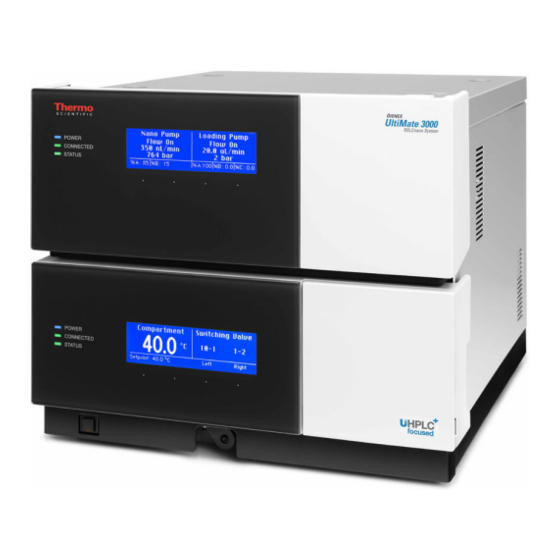
Page 30: Front Panel Elements
UltiMate 3000 Series: NCS-3500RS and NCP-3200RS 2.4 Front Panel Elements Fig. 1: Front panel view (here NCS-3500RS) Element Function Standby button Switches the module to Standby mode (the LED is lighted). To cancel Standby mode and resume operation, press the Standby button again (the LED is not lighted). - Page 31 UltiMate 3000 Series: NCS-3500RS and NCP-3200RS Element Function Pump and column compartment status LEDs Power The LEDs are blue when the module power is on. Connected The LEDs are green when the module is connected in Chromeleon. Status Status LED (pump module) The LED is green when the pump is ready for operation.
-
Page 32: Rear Panel
UltiMate 3000 Series: NCS-3500RS and NCP-3200RS 2.5 Rear Panel Fig. 2: Rear panel view Description Power switch (→ page 25) Fuse cartridge (→ page 25) Main power receptacle (→ page 42) Digital I/O ports (→ page 25) for communication with external devices, for example, a mass spectrometer Solvent Rack port for connection of a SRD-3x00 Solvent Rack (→... -
Page 33: Power Switch
UltiMate 3000 Series: NCS-3500RS and NCP-3200RS 2.5.1 Power Switch The main power switch is on the rear panel. The main power switch is used to turn the device on or off. 2.5.2 Fuse Cartridge The fuse cartridge contains two slow-blow fuses rated at 2 A (NCP-3200RS) or 4 A (NCS- 3500RS). -
Page 34: Interior Components
UltiMate 3000 Series: NCS-3500RS and NCP-3200RS 2.6 Interior Components Fig. 3: Interior components (here NCS-3500RS with Classic flow meter) Description NCS-3500RS only Column compartment, here with one column switching valve (detailed view → page 229) Pump module with Description NC pump (detailed view → page 220) Detector of rear seal wash system (→... -
Page 35: Fluid Connections
UltiMate 3000 Series: NCS-3500RS and NCP-3200RS 2.7 Fluid Connections The fluid components are located behind the front panel doors of the pump module and column compartment. The module is designed to provide easy access to the fluid components. Pump Module Tilt the front cover of the pump module upward. - Page 36 UltiMate 3000 Series: NCS-3500RS and NCP-3200RS When connecting the capillaries and routing them to other system modules, observe the general information in section 4.2 (→ page 57). For more information about the liquid flow paths in the module, see section 8 (→ page 219). Page 28 Operating Instructions...
-
Page 37: Pump Module
UltiMate 3000 Series: NCS-3500RS and NCP-3200RS 2.8 Pump Module The following sections provide a brief overview of the key features of the pump module. 2.8.1 Rear Seal Wash System The pump module is equipped with an active rear seal wash system. Rear seal washing helps avoiding damages to the pistons, piston seals, and support rings, and thus prolongs the seal lifetime. -
Page 38: Flow Meter
UltiMate 3000 Series: NCS-3500RS and NCP-3200RS 2.8.2 Flow Meter The flow meter, which is located above the pump heads of the NC pump, controls the required partial flows of the two solvent channels so that the selected target flow and the selected solvent composition are reliably met. - Page 39 UltiMate 3000 Series: NCS-3500RS and NCP-3200RS ProFlow Flow Meter Flow Connections Fig. 7: ProFlow flow meter Description For capillary connection… Flow meter inlet (from left pump head) From left pump head to flow meter With built-in inline filter Flow meter inlet (from right pump head) From right pump head to flow meter With built-in inline filter Flow meter outlet (pump outlet)
-
Page 40: Leak Sensor
UltiMate 3000 Series: NCS-3500RS and NCP-3200RS 2.8.3 Leak Sensor A leak sensor is installed inside the pump module. Leak detection is enabled as a standard when the module is shipped. If liquid collects in the drip tray under the fluid connections, the leak sensor reports a leak. The Status LED on the front panel door turns red. -
Page 41: Inline Filter (Loading Pump)
UltiMate 3000 Series: NCS-3500RS and NCP-3200RS 2.8.5 Inline Filter (Loading Pump) The loading pump has an inline filter that is located below the pump head. The filter volume is 10 µL. The filter frit is a titanium frit with a porosity of 2 µm. Inline filter Fig. -
Page 42: Column Compartment
UltiMate 3000 Series: NCS-3500RS and NCP-3200RS 2.9 Column Compartment The following sections provide a brief overview of the key features of the column compartment. 2.9.1 Gas and Humidity Sensors A gas sensor and a humidity sensor are installed inside the column compartment. The sensors detect any gas or humidity that may accumulate in the column chamber. -
Page 43: Operation From Chromeleon
UltiMate 3000 Series: NCS-3500RS and NCP-3200RS 2.10 Operation from Chromeleon The module can be controlled by the Chromeleon Chromatography Management System. To do so, an appropriate Chromeleon version and license are required. Two modes of software control are available: • Direct Control With direct control, you select operating parameters and commands in the Commands (F8) dialog box. -
Page 44: System Wellness, Predictive Performance, And Diagnostics
UltiMate 3000 Series: NCS-3500RS and NCP-3200RS 2.11 System Wellness, Predictive Performance, and Diagnostics System Wellness monitors the health of the module. Therefore, the module supports several performance and reliability features that can help you detect small problems before they turn into big ones: •... -
Page 45: Installation
UltiMate 3000 Series: NCS-3500RS and NCP-3200RS 3 Installation 3.1 Facility Requirements The installation site must meet the following requirements: • The main power switch and the main power receptacle are on the rear panel. Make sure that ♦ Free and unrestricted access to the main power switch is ensured at all times. ♦... - Page 46 UltiMate 3000 Series: NCS-3500RS and NCP-3200RS 1. Only NCS-3500RS Place the shipping container on the floor, remove the container cover, and take out the spacer box. The NCS packaging box may remain in the bottom part of the shipping container. 2.
-
Page 47: Positioning The Module In The Ultimate 3000 Rslcnano System
UltiMate 3000 Series: NCS-3500RS and NCP-3200RS 3.3 Positioning the Module in the UltiMate 3000 RSLCnano System If the module is part of an UltiMate 3000 RSLCnano system, stack the individual modules (→ Fig. 12) and interconnect them on the rear panel (→ Fig. 13). The arrangement of the system modules depends on the application. - Page 48 UltiMate 3000 Series: NCS-3500RS and NCP-3200RS SRD-3400 Optional Digital I/O for MS connection NCS-3500RS VWD-3400RS WPS-3000TPL RS Fig. 13: Example for the rear panel connections on an UltiMate 3000 RSLCnano system Thermo Fisher Scientific recommends interconnecting all modules of the RSLCnano system and then connecting the system to the Chromeleon computer with only one connection.
-
Page 49: Connecting The Module
UltiMate 3000 Series: NCS-3500RS and NCP-3200RS 3.4 Connecting the Module 3.4.1 General Information If you want to operate the module from Chromeleon Before you connect the module to the USB port on the Chromeleon computer and turn on the module power, verify that Chromeleon is installed on the computer and that the license code is entered. -
Page 50: Connecting The Power Cord
UltiMate 3000 Series: NCS-3500RS and NCP-3200RS 3.4.3 Connecting the Power Cord Use the power cord shipped with the module to connect the module to the main power source. Connect the power cord from the main power receptacle on the rear panel (→... -
Page 51: Setting Up The Module In Chromeleon
UltiMate 3000 Series: NCS-3500RS and NCP-3200RS 3.5 Setting Up the Module in Chromeleon This section provides brief instructions for setting up the module in Chromeleon. For details, see the Chromeleon Help. Tip: When the module is connected to the Chromeleon computer, verify that the Chromeleon software is installed before turning on the power to the module for the first time. - Page 52 UltiMate 3000 Series: NCS-3500RS and NCP-3200RS To resolve the problem: a) Click Cancel to exit the wizard. b) Turn off the power to the module. c) Install Chromeleon. d) Turn on the power to the module. Windows will now detect the module and install the USB software for the module automatically.
-
Page 53: Installing The Module
UltiMate 3000 Series: NCS-3500RS and NCP-3200RS 3.5.2 Installing the Module After the USB software for the module has been installed (→ page 43), install and configure the module in Chromeleon: 1. Start the Chromeleon Server Monitor and the Chromeleon server if they are not yet running (→... -
Page 54: Configuring The Module
UltiMate 3000 Series: NCS-3500RS and NCP-3200RS 3.5.3 Configuring the Module 3.5.3.1 Initial Installation On each configuration page for the module, check and change the settings if necessary and select additional settings if needed. You may reopen the configuration pages later again to change the settings (→... - Page 55 UltiMate 3000 Series: NCS-3500RS and NCP-3200RS Download • Click the Download button to transfer the firmware version available for the module in Chromeleon to the module. The button appears dimmed if the virtual mode is enabled. The module is shipped with the most recent firmware version. If a firmware update is ever required, follow the steps in section 7.14 (→...
- Page 56 UltiMate 3000 Series: NCS-3500RS and NCP-3200RS ♦ Degasser Control Click the arrow of the Degasser Control box and select External on the list if a SRD-3x00 Solvent Rack is connected to the module. With this setting, the degasser in the Solvent Rack can be operated and monitored via the pump module. The related commands and properties are available, for example, in the Commands dialog box (under PumpModule).
- Page 57 UltiMate 3000 Series: NCS-3500RS and NCP-3200RS Flow • Shows the allowed flow range. Enter a new value in the Minimum and/or Maximum box to change the limits for the flow rate within the allowed range. On the Limits (Loading) page, under Flow Unit, you can select the unit in which the loading pump flow is displayed (µl/min or ml/min).
- Page 58 UltiMate 3000 Series: NCS-3500RS and NCP-3200RS Oven / Valves Page Displays the name used to identify the column compartment in Chromeleon and sets whether the temperature is recorded as a separate channel and which column switching valves are installed. Fig. 17: Oven / Valves page Oven Device Name (default name ColumnOven) •...
- Page 59 UltiMate 3000 Series: NCS-3500RS and NCP-3200RS Columns Page The Columns page shows all columns that are available for column monitoring (→ page 34). Fig. 18: Columns page Select the columns for which you want to use column identification by the check box in the Enabled column.
- Page 60 UltiMate 3000 Series: NCS-3500RS and NCP-3200RS Relays Page The Relays page lists all available relays. Select a check box to enable the relay. If a check box is cleared, the relay will not be available in Chromeleon. To change a relay name, overwrite the existing name directly in the corresponding line.
- Page 61 UltiMate 3000 Series: NCS-3500RS and NCP-3200RS 3.5.3.2 Changing the Configuration Properties To change the standard configuration settings, reopen the configuration pages. 1. Start the Server Configuration program (→ page 45). 2. Right-click the module in the timebase and click Properties on the menu. 3.
- Page 62 UltiMate 3000 Series: NCS-3500RS and NCP-3200RS Page 54 Operating Instructions...
-
Page 63: Preparation For Operation (Startup)
UltiMate 3000 Series: NCS-3500RS and NCP-3200RS 4 Preparation for Operation (Startup) 4.1 Overview Important: The module is filled with 2-propanol when being shipped from the factory. During initial operation of the module, make sure that the solvents used are miscible with 2-propanol. Otherwise, use an appropriate intermediate solvent. - Page 64 UltiMate 3000 Series: NCS-3500RS and NCP-3200RS 7. Pump Module a) Set up the seal wash system (→ page 67) and flush the system with the seal wash solution (→ page 67). b) This step depends on the flow meter that is installed: ♦...
-
Page 65: Capillaries And Capillary Routing
UltiMate 3000 Series: NCS-3500RS and NCP-3200RS 4.2 Capillaries and Capillary Routing The following sections provide information about how to connect capillaries and route them inside the module and to the other modules in your UltiMate 3000 system. 4.2.1 Connecting and Handling Capillaries When connecting capillaries to the module, observe the following general precautions: •... - Page 66 UltiMate 3000 Series: NCS-3500RS and NCP-3200RS ♦ Viper fitting with torque toothing (NCS-3500RS) Loosen or tighten these Viper connections only with your hand and by using the special installation tool (part no. 6040.2314). The installation tool is provided in the accessories kit for the NCS. When tightening a connection, first tighten the connection hand-tight.
- Page 67 UltiMate 3000 Series: NCS-3500RS and NCP-3200RS ♦ Conventional fitting connections (non-Viper) Do not over-tighten these fitting connections. If you observe leakage on the connection, tighten a little further. If leakage still exists, clean the connection port with a cleaning swab (part no.
-
Page 68: Routing Capillaries
UltiMate 3000 Series: NCS-3500RS and NCP-3200RS 4.2.2 Routing Capillaries When routing capillaries in the module or to other system modules, observe the following general information: Pump Module • Two passages in the enclosure bottom of the pump module (→ Fig. 4, page 27) facilitate routing the capillaries to the modules that are located below the pump module and ensure the shortest possible connection. - Page 69 UltiMate 3000 Series: NCS-3500RS and NCP-3200RS Place the capillaries in such a manner that they do not open a small path for ambient air into the column chamber (that is, place the capillaries preferably in a 90-degree angle related to the door seal). An improper seal may reduce the heating performance of the column compartment.
-
Page 70: Solvent Reservoirs
UltiMate 3000 Series: NCS-3500RS and NCP-3200RS 4.3 Solvent Reservoirs For the secure and functional positioning of the solvent reservoirs, the UltiMate 3000 system series includes Solvent Racks with and without integrated vacuum degasser (→ page 20). In an UltiMate 3000 RSLCnano system, a SRD-3400 Solvent Rack with analytical 4-channel vacuum degasser should be used together with the NCS-3500RS. -
Page 71: Connecting The Solvent Reservoirs
UltiMate 3000 Series: NCS-3500RS and NCP-3200RS • As a standard, filter holders with 10 µm stainless steel frits are provided in the accessories kit of the Solvent Rack. Do not use these frits with the module. Replace the stainless steel frits with the 10 µm PEEK frits from the accessories kit of the module. Open the filter holder and remove the filter frit. - Page 72 UltiMate 3000 Series: NCS-3500RS and NCP-3200RS 7. Recommended For the secure and functional positioning of the solvent reservoirs, place them in the tray of the Solvent Rack. 8. Keep the following in mind for NC pump operation and maintenance: When the fluid components of the NC pump are filled with liquid and the solvent reservoirs are located above the pump outlet during pump operation, the hydrostatic pressure in the system may cause eluent to escape when you open a fluid connection in the NC pump.
-
Page 73: Connecting Drain Tubing
UltiMate 3000 Series: NCS-3500RS and NCP-3200RS 4.4 Connecting Drain Tubing To discharge liquids that might have accumulated in the interior and the seal wash solution, the module has two drain ports at the bottom right. Fig. 26: Drain port (here at the bottom front) Direct liquid leaks to waste through the drain system of the UltiMate 3000 system. - Page 74 UltiMate 3000 Series: NCS-3500RS and NCP-3200RS Verify that the seal wash solution is discharged properly to the waste. 1. Remove the seal wash tubing from the detector. Seal wash tubing Detector of seal wash system Fig. 27: Detector of the seal wash system 2.
-
Page 75: Pump Module
UltiMate 3000 Series: NCS-3500RS and NCP-3200RS 4.5 Pump Module 4.5.1 Setting Up the Rear Seal Wash System The peristaltic pump is installed at the top left in the pump module. The tubing under the peristaltic pump lever remains compressed and does not relax, thus blocking the wash solution. - Page 76 UltiMate 3000 Series: NCS-3500RS and NCP-3200RS b) Draw seal wash solution into a syringe at the open end of the tubing. Press the lever of the peristaltic pump to the right so that the liquid can easily pass the system. c) Reconnect the tubing to the detector.
-
Page 77: Flow Meter Settings
UltiMate 3000 Series: NCS-3500RS and NCP-3200RS 4.5.2 Flow Meter Settings Relevant only for the NC pump To be able to use a certain solvent with the NC pump, consider the setting for the respective flow meter: • With the ProFlow flow meter, the solvent type must be set (→ see page 70). •... - Page 78 UltiMate 3000 Series: NCS-3500RS and NCP-3200RS Setting the Solvent Type (ProFlow Flow Meter) To set the solvent type for the solvent that you are using, follow these steps: 1. In Chromeleon, open the Commands dialog box for the NC pump (→ page 89). 2.
- Page 79 UltiMate 3000 Series: NCS-3500RS and NCP-3200RS Setting the Solvent Viscosity (Classic Flow Meter) To set the viscosity for the solvent that you are using, follow these steps: 1. In Chromeleon, open the Commands dialog box for the NC pump (→ page 89). 2.
-
Page 80: Purging The Pumps
UltiMate 3000 Series: NCS-3500RS and NCP-3200RS 4.5.3 Purging the Pumps Purging means rinsing the system for a certain time (for the loading pump at a higher flow rate). Purging is required to • Remove the 2-propanol with which the module is filled during shipment completely from the pump before you begin sample analysis. - Page 81 UltiMate 3000 Series: NCS-3500RS and NCP-3200RS 4.5.3.1 Purging the NC Pump The purge procedure for the NC pump consists of two steps: 1. Purging the pump heads (separately or together) 2. Purging the flow meter To make sure that the pump is free of air bubbles, both steps must be performed in the correct order.
- Page 82 UltiMate 3000 Series: NCS-3500RS and NCP-3200RS 3. Purge the pump head from Chromeleon or from the pump display. To purge the pump heads from Chromeleon a) In Chromeleon, open the Commands dialog box for the NC pump. The properties and commands for purging the NC pump appear under PumpModule >...
- Page 83 UltiMate 3000 Series: NCS-3500RS and NCP-3200RS c) On the Purge screen, select Start for the pump head that you want to purge (or for both). The pump head is purged for the time specified under Purge Time. The Purge Time is set on the Preferences menu (→...
- Page 84 UltiMate 3000 Series: NCS-3500RS and NCP-3200RS To purge the flow meter from the pump display a) On the pump display, select the Control menu for the NC pump and select Purge (→ page 101). b) Choose Select and Execute to open the Purge screen. c) On the Purge screen, select Start for the flow meter.
- Page 85 UltiMate 3000 Series: NCS-3500RS and NCP-3200RS To purge the pump from Chromeleon a) In Chromeleon, open the Commands dialog box for the loading pump. The properties and commands for purging the loading pump appear under PumpModule > LoadingPump. b) Set the channel to be purged to 100% (for example, %A). In Chromeleon, you cannot set %A directly.
-
Page 86: Column Compartment
UltiMate 3000 Series: NCS-3500RS and NCP-3200RS 4.6 Column Compartment 4.6.1 Installing a Column Switching Valve The following column switching valves are available: Column Switching Valve Part No. 2-position, 6-port switching valve 6041.0004 2-position, 10-port switching valve 6041.0001 1. Do not touch any metal or plastic parts inside the column chamber while the temperature is higher than 50 °C. - Page 87 UltiMate 3000 Series: NCS-3500RS and NCP-3200RS 4. Push the valve onto the actuator until it locks in place. If the valve does not lock in place, the actuator may not be in the correct position. Follow these steps: a) Perform the Catch Head command for the valve that you want to install: In Chromeleon Open the Commands dialog box for the column oven, select ColumnOven_Wellness, and perform the LeftValveCatchHead or...
-
Page 88: Installing A Separation Column
UltiMate 3000 Series: NCS-3500RS and NCP-3200RS 4.6.2 Installing a Separation Column Three column brackets are installed in the column chamber at the factory. Attach the columns to the brackets using the special column clips from the NCS accessories kit. 1. A column clip consists of two pieces. To remove the ring from the bottom part, slightly press the ring in the direction of the arrows. - Page 89 UltiMate 3000 Series: NCS-3500RS and NCP-3200RS 5. If you want to use column identification Attach the column ID chip card to the column. Two chip cards are provided in the accessories kit of the module. Wrap the ribbon around the column, pass the shank of the rivet through a hole, and press down to unite the two parts.
-
Page 90: Installing A Trap Column
UltiMate 3000 Series: NCS-3500RS and NCP-3200RS 4.6.3 Installing a Trap Column Certain applications, for example, preconcentration, require the installation of a trap column. The trap column is connected directly to the column switching valve. When installing the trap column, observe the direction of flow (indicated by an arrow on the column). -
Page 91: Equilibrating The System
UltiMate 3000 Series: NCS-3500RS and NCP-3200RS 4.7 Equilibrating the System Before using the module for sample analysis, equilibrate the UltiMate 3000 system: Tip: If the module has not been in use for a longer period (> several days), it will take some time until the module is ready for operation again: ♦... - Page 92 UltiMate 3000 Series: NCS-3500RS and NCP-3200RS Page 84 Operating Instructions...
-
Page 93: Operation And Maintenance
UltiMate 3000 Series: NCS-3500RS and NCP-3200RS 5 Operation and Maintenance The module is controlled by the Chromeleon Chromatography Management System. For details, see section 5.3 (→ page 88). In addition, function keys and menus are available on the front panel displays to facilitate operation during, for example, initial installation, diagnostics, and maintenance, allowing you to perform certain actions directly from the module. -
Page 94: Status Screen
UltiMate 3000 Series: NCS-3500RS and NCP-3200RS 5.2 Status Screen When the self test was successful, the status screens appear on the front panel displays. You can adjust the screen brightness or screen contrast to your requirements from Chromeleon or on the front panel displays (→ page 125 for the pump display and page 131 for the column compartment display). -
Page 95: Column Compartment
UltiMate 3000 Series: NCS-3500RS and NCP-3200RS 5.2.2 Column Compartment The picture shows the status screen for the column compartment: Compartment Switching Valves 40.0 10-1 °C Setpoint: 40.0°C Left Right Fig. 43: Status screen (example) Under ... The following information appears … Compartment Current column temperature (in °C) Setpoint... -
Page 96: Operation From Chromeleon
UltiMate 3000 Series: NCS-3500RS and NCP-3200RS 5.3 Operation from Chromeleon Before you begin, verify that 1. The Chromeleon software is installed on the computer and the license code is entered. 2. The module is connected to the Chromeleon computer by means of a USB connection. 3. -
Page 97: Direct Control
UltiMate 3000 Series: NCS-3500RS and NCP-3200RS 5.3.2 Direct Control With direct control, you select operating parameters and commands in the Commands (F8) dialog box. Direct commands are executed as soon as they are entered. For routine operation, most parameters and commands are available also on a control panel. To open the Commands dialog box for the module 1. - Page 98 UltiMate 3000 Series: NCS-3500RS and NCP-3200RS b) To see the parameters and commands that are available for the column compartment, click the plus sign next to ColumnOven. 5. The commands and parameters available in the dialog box vary, depending on the ♦...
- Page 99 UltiMate 3000 Series: NCS-3500RS and NCP-3200RS system-wide functions, for example, creating and running sequences. For more information about panel tabsets, see the Chromeleon Help. 2. On the Panel Tabset for your timebase, click the page for the module. Fig. 46: Control panel (here for the NCS-3500RS) 3.
-
Page 100: Automated Control
UltiMate 3000 Series: NCS-3500RS and NCP-3200RS 5.3.3 Automated Control With automated control, you create a program file (PGM) for automated operation of the module. You can create programs automatically with the software wizard or manually by editing an existing program. In addition to programs for sample analysis, you can also create programs for special purposes, for example, to automate system shutdown (→... - Page 101 UltiMate 3000 Series: NCS-3500RS and NCP-3200RS 2. Change the program settings as needed. The easiest way is to edit a program is to do this in the Device Views (→ Fig. 47). Click a device icon and change the settings on the device pages. Editing the program in the Device Views ensures correct command syntax.
-
Page 102: Function Keys And Menus On The Display
UltiMate 3000 Series: NCS-3500RS and NCP-3200RS 5.4 Function Keys and Menus on the Display Function keys and menus are available on the front panel displays. Thus, you can make several settings or execute certain commands directly from the module. • For information about the function keys, see section 5.4.1 and page 97. - Page 103 UltiMate 3000 Series: NCS-3500RS and NCP-3200RS Function Key Description Only NCP-3200RS Set Flow Opens the SetFlow dialog. You can set the flow rate also on the Control menu (→ page 101). Purge Only NCP-3200RS Opens the Purge dialog. Select the component that you want to purge (left and/or right pump head or flow meter).
-
Page 104: Menu
UltiMate 3000 Series: NCS-3500RS and NCP-3200RS 5.4.2 Menu To open the menus for the pump and column compartment, select the Menu key on the front panel display. The module type determines which menus and parameters are available. For an overview of the pump menus, see section 5.4.2.2 (→ page 98). For an overview of the menus that are available for the column compartment, see section 5.4.2.3 (→... - Page 105 UltiMate 3000 Series: NCS-3500RS and NCP-3200RS The selected menu item or parameter determines which keys appear on the navigation bar: To … Select ... Return to the previous entry on a list. ∧ If the list contains 5 or more items, you can use the arrow up key to scroll up through the list, after reaching the first line (→...
- Page 106 UltiMate 3000 Series: NCS-3500RS and NCP-3200RS 5.4.2.2 Pump Menus The pump type (NC pump or loading pump) determines which menus, commands, and parameters are available. Fig. 50 provides an overview of the menus for the NC pump. For an overview of the menus for the loading pump, see Fig. 51 (→ page 99). For information about the commands and parameters that are available in the individual menus, see sections 5.4.2.2.1 through 5.4.2.2.5 (→...
- Page 107 UltiMate 3000 Series: NCS-3500RS and NCP-3200RS Main 1. Control 2. Preferences 3. Diagnostics 4. Configuration 1. Flow 1. Degasser 1. Display & Soft Keys 1. Self Test 2. Flow Rate 2. Purge Time 2. Leak Sensor Mode 2. Compression 3. %A 3.
- Page 108 UltiMate 3000 Series: NCS-3500RS and NCP-3200RS 5.4.2.2.1 Main Menu The Main menu provides top-level access to the menu structure. To open the Main menu for the related pump, show the function keys and select Menu (→ page 94). From the Main menu, you can open the following menus: Control •...
- Page 109 UltiMate 3000 Series: NCS-3500RS and NCP-3200RS 5.4.2.2.2 Control Menu On the Control menu, you can make the different settings for pump operation. To … Select … Start the pump flow with the selected flow rate (on) or to stop the flow Flow (off).
- Page 110 UltiMate 3000 Series: NCS-3500RS and NCP-3200RS 5.4.2.2.3 Preferences Menu On the Preferences menu, you can make the basic settings for the related pump. To … Select … Turn the degasser in a SRD-3x00 Solvent Rack that is connected to the module Degasser on or off.
- Page 111 UltiMate 3000 Series: NCS-3500RS and NCP-3200RS To … Select … Loading pump only Workload See the workload of the related pump head since the pump has been operated for the first time. The workload is calculated from the flow rate, pressure, and time.
- Page 112 UltiMate 3000 Series: NCS-3500RS and NCP-3200RS 5.4.2.3 Column Compartment Menus Fig. 52 provides an overview of the menus that are available for the column compartment. For information about the commands and parameters that are available in the individual menus, see sections 5.4.2.3.1 through 5.4.2.3.4 (→ page 105 and following pages). Section 5.4.2.1 provides information about the general menu layout and function keys on the navigation bar (→...
- Page 113 UltiMate 3000 Series: NCS-3500RS and NCP-3200RS 5.4.2.3.1 Main Menu The Main menu provides top-level access to the menu structure. To open the Main menu, show the function keys and select Menu (→ page 94). From the Main menu, you can open the following menus: Control •...
- Page 114 UltiMate 3000 Series: NCS-3500RS and NCP-3200RS 5.4.2.3.4 Configuration Menu The Configuration menu provides information about the configuration of the column compartment and allows you to make the required settings or change the settings. To … Select … Set the display and function key parameters: Display &...
-
Page 115: Information For Operating The Pump
UltiMate 3000 Series: NCS-3500RS and NCP-3200RS 5.5 Information for Operating the Pump This section provides specific information about settings and functions that should be considered for operating the pump: To learn more about ... See page ... Choosing the solvents Interdependency of column pressure and maximum flow rate (NC pump) Establishing and saving the solvent viscosity (NC pump) Setting the flow rate, flow acceleration, and flow deceleration... -
Page 116: Choosing The Solvents
UltiMate 3000 Series: NCS-3500RS and NCP-3200RS 5.5.1 Choosing the Solvents Observe the following precautions for solvent selection: • Observe the precautionary statements in section 1.2.2 (→ page 5). • The pump is primed with 2-propanol. During initial operation of the module, make sure that the solvents used are miscible with 2-propanol. - Page 117 UltiMate 3000 Series: NCS-3500RS and NCP-3200RS • In an UltiMate 3000 system, some components are made of PEEK. This polymer has superb chemical resistance to most organic solvents. However, it tends to swell when in contact with trichlormethane (CHCl ), dimethyl sulfoxide (DMSO), or tetrahydrofuran (THF).
-
Page 118: Interdependency Of Column Pressure And Maximum Flow Rate
UltiMate 3000 Series: NCS-3500RS and NCP-3200RS 5.5.2 Interdependency of Column Pressure and Maximum Flow Rate 5.5.2.1 NC Pump with a ProFlow Flow Meter Overview Each flow channel of the ProFlow flow meter comprises a closed control loop that includes the pump (nos. 1a and 1b) and a thermal flow sensor (nos. 5a and 5b). The flow sensors measure the current flow rates and the pump speeds are controlled so that the flow rates match the set values. - Page 119 UltiMate 3000 Series: NCS-3500RS and NCP-3200RS ProFlow flow meter: Interdependency of column pressure and the maximum flow rate The maximum column pressure depends on the solvent that is used in solvent channel B and the flow rate. The table below shows which column pressures can be delivered at the given flow rates for a number of solvents: Maximum possible column pressure at flow rate Solvent (%B)
- Page 120 UltiMate 3000 Series: NCS-3500RS and NCP-3200RS 5.5.2.2 NC Pump with a Classic Flow Meter Overview The NC pump has two transducers for the primary pressure and one transducer for the system pressure. The primary pressures are controlled in such a way that the partial flows through the fluidic resistors (→...
- Page 121 UltiMate 3000 Series: NCS-3500RS and NCP-3200RS Classic flow meter: Interdependency of column pressure and the maximum flow rate The pump has been designed for column pressures of up to 80 MPa. This value refers to the nominal flow and solvents with a maximum viscosity of 100 % (equivalent to water). The primary pressures can be up to 100 MPa, but the flow restrictors cause a pressure drop that depends on the selected flow rate, the viscosity of the solvents, and the solvent composition.
-
Page 122: Adding Solvents To The Flow Meter Configuration
UltiMate 3000 Series: NCS-3500RS and NCP-3200RS 5.5.3 Adding Solvents to the Flow Meter Configuration Relevant only for the NC pump If the viscosity (Classic flow meters) or type (ProFlow flow meter) for the solvent that you are using is not yet available in Chromeleon, proceed as follows: •... - Page 123 UltiMate 3000 Series: NCS-3500RS and NCP-3200RS 2. On the Control menu, select Diagnostics, and then select Solvent Calibration. A wizard guides you through the procedure. The procedure takes about 60 minutes. Tip: During solvent calibration, a nanoViper capillary needs to be connected to the flow meter outlet.
- Page 124 UltiMate 3000 Series: NCS-3500RS and NCP-3200RS 2. On the Control menu, select Diagnostics, and then select Viscosity Measurement; as an alternative, on the tabset panel, in the NC Pump group, click More Options, and in the Viscosity Measurement group, click Start. A wizard guides you through the procedure.
- Page 125 UltiMate 3000 Series: NCS-3500RS and NCP-3200RS 3. Enter the name of the solvent and the viscosity. Note the tips further down in this section. ♦ To add a new entry Click into the line marked by the asterisk (*) in the leftmost column and type the name and viscosity value in this line.
- Page 126 UltiMate 3000 Series: NCS-3500RS and NCP-3200RS ♦ To delete an entry Select the entry that you want to delete. To do so, click in the leftmost column and press the Del key. A line can be deleted only if the entry has been correct. 4.
-
Page 127: Setting The Flow Rate, Flow Acceleration, And Flow Deceleration
UltiMate 3000 Series: NCS-3500RS and NCP-3200RS 5.5.4 Setting the Flow Rate, Flow Acceleration, and Flow Deceleration In Chromeleon or on the pump menus, you can set how fast the pump starts delivering with the selected flow rate (flow acceleration) and how fast the pump flow is reduced (flow deceleration). -
Page 128: Setting The Pressure Limits
UltiMate 3000 Series: NCS-3500RS and NCP-3200RS 5.5.5 Setting the Pressure Limits The pump firmware and Chromeleon provide standard values for the upper and lower pressure limits. The limits depend on the pump type. You are free to change the limits within the allowed pressure range. -
Page 129: Recording The Pump Signals
UltiMate 3000 Series: NCS-3500RS and NCP-3200RS 5.5.6 Recording the Pump Signals On the Signals page, the check box for the column pressure of the NC pump and the pressure of the loading pump are selected by default when the module is installed and configured in Chromeleon (→... -
Page 130: Rear Seal Wash System
UltiMate 3000 Series: NCS-3500RS and NCP-3200RS 5.5.7 Rear Seal Wash System Rear seal washing helps avoiding damages to the pistons, piston seals, and support rings, and thus prolongs the seal lifetime. For information about how to set up the rear seal wash system, see page 67. - Page 131 UltiMate 3000 Series: NCS-3500RS and NCP-3200RS 5.5.7.3 What happens …. Correct functioning of the rear seal wash system During the delivery period of the peristaltic pump, liquid reaches the detector of the rear seal wash system. This means that the seal wash system performs correctly. The tubing is all right and the peristaltic pump works correctly.
-
Page 132: Purging The Pumps
UltiMate 3000 Series: NCS-3500RS and NCP-3200RS 5.5.8 Purging the Pumps If you observe pressure pulsation, a high noise level, or pulsation during the operation of the pump or if the analysis is not reproducible, this may indicate that there are air bubbles in the system. -
Page 133: Adjusting The Screen Brightness Or Contrast
UltiMate 3000 Series: NCS-3500RS and NCP-3200RS 5.5.10 Adjusting the Screen Brightness or Contrast You can adjust the screen brightness or screen contrast to your requirements from Chromeleon or on the pump display. To do so, select one of the following alternatives: In Chromeleon, open the Commands dialog box for the pump module. - Page 134 UltiMate 3000 Series: NCS-3500RS and NCP-3200RS General Guidelines for Degasser Operation • Thermo Fisher Scientific recommends always leaving the degasser on while the pump is • Turning off the module to which the SRD is connected also turns off the SRD. The same applies to Standby mode.
-
Page 135: Information For Operating The Column Compartment
UltiMate 3000 Series: NCS-3500RS and NCP-3200RS 5.6 Information for Operating the Column Compartment This section provides specific information about settings and functions that should be considered for operating the column compartment: To learn more about ... See page ... Turning on temperature control See below. - Page 136 UltiMate 3000 Series: NCS-3500RS and NCP-3200RS 3. Select Temperature and Nominal, and then enter the temperature. Temperature control becomes active and TempCtrl is automatically set to On. Fig. 57: Turning on temperature control Set TempCtrl to Off if you do not want to use temperature control for a certain application. If you want to use temperature control later again, set TempCtrl to On.
-
Page 137: Activating Column Identification (Column Id)
UltiMate 3000 Series: NCS-3500RS and NCP-3200RS 5.6.2 Activating Column Identification (Column ID) 1. Verify that the column ID chip card is attached to the column (→ page 81). 2. Insert the chip card, with the chip facing down, into one of the four chip card readers (A - D). -
Page 138: Adjusting The Sensitivity Of The Gas And Humidity Sensors
UltiMate 3000 Series: NCS-3500RS and NCP-3200RS Operational column properties • Chromeleon determines and updates the operational information upon each injection. The operational column properties are, for example, the date of the first injection, the date of the last injection, the maximum flow rate while the column is in use, or the total volume of sample that has been injected onto the column. -
Page 139: Recording The Temperature Signal
UltiMate 3000 Series: NCS-3500RS and NCP-3200RS 5.6.4 Recording the Temperature Signal On the Oven / Valves page, the check box for the temperature channel is selected by default when the NCS-3500RS is installed and configured in Chromeleon (→ page 50). With this setting, Chromeleon generates the ColumnOven_Temp channel for recording the temperature signal. -
Page 140: Special Functions In Chromeleon
UltiMate 3000 Series: NCS-3500RS and NCP-3200RS 5.7 Special Functions in Chromeleon This section provides a brief overview of some special functions that Chromeleon supports for the module. To learn more about ... See page Predictive performance See below. Diagnostics tests Equilibration Time and Ready Temp Delta Using the digital inputs and outputs Operational Qualification and Performance Qualification... - Page 141 UltiMate 3000 Series: NCS-3500RS and NCP-3200RS Module After you have … Perform the following command … Loading pump Replaced the entire pump head assembly CheckValveServiceDone, PistonsChanged, SealChanged, SupportRingChanged Column Replaced the rotor seal of the left valve LeftRotorSealChanged compartment Column Replaced the rotor seal of the right valve RightRotorSealChanged compartment...
-
Page 142: Diagnostics
UltiMate 3000 Series: NCS-3500RS and NCP-3200RS 5.7.2 Diagnostics Chromeleon supports diagnostics functions for checking the performance of certain module components. To perform the tests, the diagnostics toolkit (part no. 6040.3099) is required. The kit includes all materials required for performing the tests. Tip: The diagnostics functions in Chromeleon provide helpful information in case of problems. - Page 143 UltiMate 3000 Series: NCS-3500RS and NCP-3200RS Pump To check the … Run the … NC pump The NC pump for leakage (capillary connections, Detailed Leak Test flow meter, pump heads). Additional Recommendations Recommended for NC pumps with Classic flow meter installed: In addition to the Detailed Leak Test also run the Pressure Transducer Test and Viscosity Measurement in the given order:...
-
Page 144: Ready Temp Delta And Equilibration Time
UltiMate 3000 Series: NCS-3500RS and NCP-3200RS 5.7.3 Ready Temp Delta and Equilibration Time The Ready property indicates whether the column compartment is ready for operation. When the column compartment is in the status NotReady, you cannot start the analysis. Keep in mind that the settings for Ready Temp Delta and Equilibration Time influence the time that the column compartment needs to enter the Ready state: Setting Description... -
Page 145: Using The Digital Inputs And Outputs (Digital I/O)
UltiMate 3000 Series: NCS-3500RS and NCP-3200RS The picture illustrates the scenario: Fig. 59: Interdependencies between ReadyTempDelta, EquilibrationTime, and Ready Observe the following: • The smaller the value is for ReadyTempDelta and the higher the value is for EquilibrationTime, the longer is takes until the column compartment is ready for operation and you can start the data acquisition and/or the analysis. -
Page 146: Recommendations For Optimally Running Systems (Best Practice)
UltiMate 3000 Series: NCS-3500RS and NCP-3200RS 5.8 Recommendations for Optimally Running Systems (Best Practice) The best stability with any chromatographic system is achieved when running the system uninterruptedly. This is true also for the NC pump that uses extremely precise pressure transducers or thermal flow sensors to control the flow rate and gradients. - Page 147 UltiMate 3000 Series: NCS-3500RS and NCP-3200RS 3. If the module was powered off by the power switch for a longer period (≥ 1 day), allow a warm-up period of 1 hour (if a ProFlow flow meter is installed) or 24 hours (if a Classic flow meter is installed) to achieve optimum reproducibility.
-
Page 148: Shutting Down The Module
UltiMate 3000 Series: NCS-3500RS and NCP-3200RS 5.9 Shutting Down the Module Observe the following precautions before interrupting the operation or before shipping the module: Tip: Observe the information on this in point 3 in section 5.8 (→ page 138) when resuming module operation. - Page 149 UltiMate 3000 Series: NCS-3500RS and NCP-3200RS • Ship the NCS-3500RS always without valves. To protect the valve drives, reinstall the foam inserts that were installed upon shipment of the NCS. • Ship the module only in the original shipping container and observe the packing instructions.
-
Page 150: Maintenance, And Maintenance And Calibration Intervals
UltiMate 3000 Series: NCS-3500RS and NCP-3200RS 5.10 Maintenance, and Maintenance and Calibration Intervals 5.10.1 General Information The module is made of high-quality components and materials to minimize maintenance requirements. All surfaces are resistant to weak acids, alkali, and organic solvents. Nevertheless, immediately wipe up all liquids spilled onto the module surface, by using lint-free cloth or paper. -
Page 151: Maintenance Intervals
UltiMate 3000 Series: NCS-3500RS and NCP-3200RS 5.10.2 Maintenance Intervals To ensure optimum performance and maximum uptime of the module, perform the maintenance procedures listed in the table at regular intervals. The exact maintenance schedule depends on a number of factors. Frequency What you should do... -
Page 152: Calibration Intervals
UltiMate 3000 Series: NCS-3500RS and NCP-3200RS Frequency What you should do... Recommended: Annually Have authorized Service personnel perform preventive maintenance once a year. 5.10.3 Calibration Intervals Relevant only for the NC pump The main reason for performing calibration is to correct shifts in retention time that may develop over time. -
Page 153: Troubleshooting
UltiMate 3000 Series: NCS-3500RS and NCP-3200RS 6 Troubleshooting 6.1 Overview The following features help you to identify and eliminate the source for problems that may occur during the operation of the module or UltiMate 3000 system. Status LEDs • ♦ The status LEDs (light emitting diodes) on the front panel provide a quick visual check of the operational status of the module. -
Page 154: Pump Block Status Indicator (Loading Pump)
UltiMate 3000 Series: NCS-3500RS and NCP-3200RS 6.2 Pump Block Status Indicator (Loading Pump) The status LED that is located on the interior front panel above the pump head of the loading pump indicates the operational status of the pump block (→ Fig. 91, page 226): Operational Status The LED is dark. -
Page 155: Messages On The Pump Display
UltiMate 3000 Series: NCS-3500RS and NCP-3200RS 6.3 Messages on the Pump Display Each time a fault or error occurs during the operation of the module, the Status LED on the front panel door changes to red and one or more messages appear on the pump display. In this case, the Prev, Next, and Clear keys appear on the navigation bar. - Page 156 UltiMate 3000 Series: NCS-3500RS and NCP-3200RS Message Remedial Action The message appears when you performed the CalibrateWP Calibration procedure failed. Cannot build up and hold command from Chromeleon and calibration failed. pressure. Possible causes are: - The purge valves are open. Close the valves. - Check that the fitting plug is installed correctly.
- Page 157 UltiMate 3000 Series: NCS-3500RS and NCP-3200RS Message Remedial Action Cannot regulate flow One or both solvent channels of the NC pump cannot build up sufficient pressure to deliver the selected flow rate. Possible causes are: - The solvent reservoir is empty. Fill the reservoir. - The pump may not have been purged sufficiently.
- Page 158 UltiMate 3000 Series: NCS-3500RS and NCP-3200RS Message Remedial Action Flow meter data read failure The data on the flow meter EEPROM could not be read. Verify that the flow meter is installed properly and perform a self test. Flow meter failure Invalid values are reported for one or more pressure transducers of the flow meter.
- Page 159 UltiMate 3000 Series: NCS-3500RS and NCP-3200RS Message Remedial Action (where x provides details on the hardware error) Hardware error during flow calibration. (x) Turn the module off and on again by pressing the power switch on the rear of the module. Repeat the solvent calibration of the ProFlow flow meter.
- Page 160 UltiMate 3000 Series: NCS-3500RS and NCP-3200RS Message Remedial Action Implausible left working The pressure values established during pump operation for the cylinder pressure. Check working pressure of the left and/or right pump head of the NC pump pressure plug. are not plausible. —or—...
- Page 161 UltiMate 3000 Series: NCS-3500RS and NCP-3200RS Message Remedial Action Left valve moving to position The left valve did not reach the specified position within a certain timeout. time. There may be no valve installed or the valve is not configured properly.
- Page 162 UltiMate 3000 Series: NCS-3500RS and NCP-3200RS Message Remedial Action New flow meter found. The message is for information only, indicating that a Classic flow Please use the pressure meter has been installed. transducer test and then Make sure that you perform the required steps for the Classic flow calibrate both working meter after installation (→...
- Page 163 UltiMate 3000 Series: NCS-3500RS and NCP-3200RS Message Remedial Action Purge pressure limit During the purge cycle, a pressure of more than 5 MPa built up. exceeded If the message appears during the purge cycle for a pump head Verify that the purge valve for the pump head is open. If it is not, open the purge valve to reduce the pressure.
- Page 164 UltiMate 3000 Series: NCS-3500RS and NCP-3200RS Message Remedial Action (where xx = additional text) Self test failed: xx This message usually appears together with another message indicating which failure occurred during the self test. Refer to this message for recommended remedial actions. Solvent rack leak detected The leak sensor in the Solvent Rack has reported a leak.
- Page 165 UltiMate 3000 Series: NCS-3500RS and NCP-3200RS Message Remedial Action The rear seal leak sensor Verify that the pump is installed in a horizontal position and that the detects drops constantly. seal wash solution can run properly to the waste. Remove the detector of the seal wash system (→ page 181). Verify that the detector seat is dry, for example, by using a lint-free cloth or tissue.
- Page 166 UltiMate 3000 Series: NCS-3500RS and NCP-3200RS Message Remedial Action NC pump Upper pressure limit exceeded The message appears when the column pressure exceeds the set upper pressure limit. In this case, the flow of the NC pump will be stopped. Too high a column pressure may be caused not only by the column itself but also by other components in the flow path of the NC pump (depending on the application).
- Page 167 UltiMate 3000 Series: NCS-3500RS and NCP-3200RS When the module is operated from Chromeleon and if communication between Chromeleon and the module cannot be established, messages may appear in the Chromeleon Audit Trail. The wording of the messages in the table refers the NCS-3500RS; however, the messages apply in the same way to the NCP-3200RS.
-
Page 168: Chromeleon Diagnostics Messages
UltiMate 3000 Series: NCS-3500RS and NCP-3200RS 6.4 Chromeleon Diagnostics Messages If the module fails a diagnostics test, perform the instructions given here and repeat the test. If the module fails the test again, contact Thermo Fisher Scientific Service for Dionex HPLC Products. - Page 169 UltiMate 3000 Series: NCS-3500RS and NCP-3200RS Viscosity Measurement failed (Classic Flow Meter only) Probable Cause Remedial Action After the piston seals have been Purge the flow meter for another 30 to 60 minutes (→ page 75). replaced, the new seals do not Afterward, repeat the test.
- Page 170 UltiMate 3000 Series: NCS-3500RS and NCP-3200RS Performance Test failed Test Result Probable Cause Remedial Action The pressure/% compression Eluent may not have been Degas the solvent. was outside specification! degassed correctly. It is likely that the wrong eluent Repeat the test. Make sure that the was chosen in test step 1 correct eluent is chosen.
-
Page 171: Operating Problems
UltiMate 3000 Series: NCS-3500RS and NCP-3200RS 6.5 Operating Problems The table provides information about common operating problems that might occur with the module or an UltiMate 3000 system and lists probable causes, and suggests remedial actions. For more information and remedial actions, see the manuals for the other modules of the UltiMate 3000 system. - Page 172 UltiMate 3000 Series: NCS-3500RS and NCP-3200RS Problem Probable Cause Remedial Action The degasser of a SRD-3x00 The Solvent Rack is not In the Chromeleon Server Configuration program, Solvent Rack that is connected properly to the module verify on the Pumps page of connected to the module does and/or the degasser is not not work (the Vacuum and...
- Page 173 UltiMate 3000 Series: NCS-3500RS and NCP-3200RS Problem Probable Cause Remedial Action Shifts in retention time for a When changing solvents, the Purge the NC pump longer period previous solvent has not been (→ page 73). removed completely from the NC pump.
- Page 174 UltiMate 3000 Series: NCS-3500RS and NCP-3200RS Problem Probable Cause Remedial Action Pressure pulsation or After a maintenance procedure Remove and reinstall the inconstant pressure (replacement of pump head, pistons (→ pages 188 piston, or piston seal) the pistons and 190). (Cont'd) are not in the appropriate position for normal operation.
- Page 175 UltiMate 3000 Series: NCS-3500RS and NCP-3200RS Problem Probable Cause Remedial Action Either no peaks or only few, With direct injection or Optimize the poorly resolved peaks appear preconcentration: The solvent chromatographic parameters. in the chromatogram. contains too much organic, the solvent does not contain enough organic in the solvent, or the mobile phase is wrong.
- Page 176 UltiMate 3000 Series: NCS-3500RS and NCP-3200RS Problem Probable Cause Remedial Action Poor peak area precision The capillary connections are not Check and tighten the installed properly or they are capillary connections. leaking. Consider using Viper capillaries. There are dead volumes in the Replace the conventional capillary connections.
- Page 177 UltiMate 3000 Series: NCS-3500RS and NCP-3200RS Problem Probable Cause Remedial Action No flow The system is leaking. Find and eliminate the leak. The eluents are degraded, dirty or Use fresh solvent. Use fresh of poor purity/quality. and appropriate solvents (MS- grade).
- Page 178 UltiMate 3000 Series: NCS-3500RS and NCP-3200RS Problem Probable Cause Remedial Action Loading pump: The piston does not contact the Check whether the piston is Flow fluctuation magnet holder. installed correctly. Reinstall the piston if needed (Cont'd) (→ page 197). The piston seals are leaking. Replace the piston seals (→...
- Page 179 UltiMate 3000 Series: NCS-3500RS and NCP-3200RS Problem Probable Cause Remedial Action The temperature in the The capillaries are placed in such Verify that the capillaries are column chamber does not a manner that ambient air can routed correctly through the change for some time enter the column chamber.
-
Page 180: Flow Sensor / Pressure Transducer Diagnostics (Nc Pump)
UltiMate 3000 Series: NCS-3500RS and NCP-3200RS 6.6 Flow Sensor / Pressure Transducer Diagnostics (NC Pump) 6.6.1 Performing a Zero Balance Test (ProFlow Flow Meter) Relevant only for the NC pump with a ProFlow flow meter installed To ensure an accurate flow rate and solvent composition, the zero balance of the thermal flow sensors and pressure transducers of the ProFlow flow meter must be calibrated from time to time. - Page 181 UltiMate 3000 Series: NCS-3500RS and NCP-3200RS • The Pressure Transducer Test must be performed when the following components have been replaced: ♦ Pump head ♦ Flow meter ♦ Flow selector As long as the retention times are stable and in the expected range, you should not •...
-
Page 182: Checking The Compression Values (Loading Pump)
UltiMate 3000 Series: NCS-3500RS and NCP-3200RS 6.7 Checking the Compression Values (Loading Pump) Relevant only for the loading pump Tip: The following applies only when the loading pump has backpressure. The compression value of the pump head can provide valuable information for troubleshooting. -
Page 183: Service
UltiMate 3000 Series: NCS-3500RS and NCP-3200RS 7 Service 7.1 General Notes and Safety Precautions The following sections describe all service and repair procedures that the user may perform. All other maintenance and service procedures must be performed only by Thermo Fisher Scientific service personnel Warning: The fluid components of the device may be filled with solvents that... - Page 184 UltiMate 3000 Series: NCS-3500RS and NCP-3200RS • Use only the original spare parts authorized for the device by Thermo Fisher Scientific. • Before returning the module for repair, contact Thermo Fisher Scientific Service for Dionex HPLC Products. An RMA (Return Material Authorization) number is required to track your module. Always use the original packaging and observe the packing instructions when shipping the module.
-
Page 185: Eliminating Leakage In The Pump Module
UltiMate 3000 Series: NCS-3500RS and NCP-3200RS 7.2 Eliminating Leakage in the Pump Module The leak sensor is installed inside the pump module. The sensor reports a leak when liquid collects in the drip tray under the fluid connections. Locate the source for the leak, eliminate the cause, and dry the leak sensor. -
Page 186: Removing Gas And Humidity From The Column Compartment
UltiMate 3000 Series: NCS-3500RS and NCP-3200RS 7.3 Removing Gas and Humidity from the Column Compartment When a certain concentration of gas or humidity is reached inside the column compartment (while the door of the column chamber is closed), the related sensor is activated and the Status LED on the front panel door changes to red. -
Page 187: Rear Seal Wash System
UltiMate 3000 Series: NCS-3500RS and NCP-3200RS 7.4 Rear Seal Wash System 7.4.1 Inspecting the Rear Seal Wash System for Leakage 1. Remove the seal wash tubing from the detector. Seal wash tubing Detector of the seal wash system Fig. 61: Detector of the seal wash system 2. -
Page 188: Replacing The Peristaltic Tubing
UltiMate 3000 Series: NCS-3500RS and NCP-3200RS 7.4.2 Replacing the Peristaltic Tubing Description Part No. Peristaltic tubing (= PharMed tubing, white) from the Tubing Kit for the Rear Seal Wash System 6040.9502 1. First, remove the seal wash tubing from the seal wash reservoir to avoid liquid spill. 2. -
Page 189: Cleaning The Detector Electrodes
UltiMate 3000 Series: NCS-3500RS and NCP-3200RS 7.4.3 Cleaning the Detector Electrodes The detector electrodes can be contaminated by deposits impairing the correct functioning of the seal wash system. 1. Remove the seal wash tubing from the detector (→ Fig. 61). 2. -
Page 190: Replacing The Check Valve Cartridges
UltiMate 3000 Series: NCS-3500RS and NCP-3200RS 7.5 Replacing the Check Valve Cartridges Two check valves are installed in the pump head: inlet check valve and outlet check valve (→ Fig. 65, page 184, nos. 11 and 13). Description Part No. Check valve cartridge, ceramics, for the NC pump and loading pump 6041.2301 (the cartridge is the same for both the inlet and outlet valve) - Page 191 UltiMate 3000 Series: NCS-3500RS and NCP-3200RS Inlet valve (nut) Inlet valve (bottom part) with opening on the front left Fig. 64: Inlet check valve NC pump Loading pump Tighten the inlet check valve hand-tight and turn the bottom part so that the inlet opening points toward the back.
-
Page 192: Pistons And Piston Seals
UltiMate 3000 Series: NCS-3500RS and NCP-3200RS 7.6 Pistons and Piston Seals Fig. 65: Pump head, pistons, and piston seals Depending on the pump version, the representation of a part may be different from the real part. However, the position of the parts is the same for all pump versions. Page 184 Operating Instructions... - Page 193 UltiMate 3000 Series: NCS-3500RS and NCP-3200RS Description Part No. NC pump Loading pump Pump head, entire assembly, with: 6041.1901A 6041.1902 Piston (sapphire) 6040.0042 (= 2 pistons) Plate of the rear seal wash system N.a. Piston seal (in plate of seal wash system) 6040.0306 (= 2 seals) (normal phase) Seal ring (rear seal wash system)
-
Page 194: Visually Inspecting The Pump For Piston Seal Leakage
UltiMate 3000 Series: NCS-3500RS and NCP-3200RS 7.6.1 Visually Inspecting the Pump for Piston Seal Leakage You can inspect the pump visually for liquid leaks from the piston seals. 1. Flush the rear seal wash system with the seal wash solution. a) Remove the seal wash tubing from the detector. - Page 195 UltiMate 3000 Series: NCS-3500RS and NCP-3200RS 7. Reconnect the seal wash tubing to the detector. Be sure to connect the tubing to the inner port (→ Fig. 66). The outer port has no function. Tip: If leakage from a pump head is observed, check also the tubing connected to the rear seal wash system.
-
Page 196: Pump Head And Pistons
UltiMate 3000 Series: NCS-3500RS and NCP-3200RS 7.6.2 Pump Head and Pistons 7.6.2.1 Removing the Pump Head and Pistons 1. Tilt the front cover upward. 2. If necessary, purge the pump to remove harmful solvents. 3. Set the pump flow rate to 0. Open the purge valve and wait until the system pressure is down to zero. - Page 197 UltiMate 3000 Series: NCS-3500RS and NCP-3200RS 9. Hold the pump head with one hand in its position, remove the pump head screw, and then remove the pump head toward you. NC pump The plate of the rear seal wash system and the pistons remain in the pump. If you want to clean or replace the pistons, remove the plate and pistons as described for the loading pump further down in this section.
- Page 198 UltiMate 3000 Series: NCS-3500RS and NCP-3200RS 7.6.2.2 Installing the Pistons and Pump Head Description Part No. Pump head (entire assembly) NC pump 6041.1901A Loading pump 6041.1902 Piston (2 pistons, sapphire) 6040.0042 1. If you removed the pistons a) Place the plate of the rear seal wash system onto the pump head. b) Inject a few drops of isopropanol into the piston cavities and insert the pistons.
- Page 199 UltiMate 3000 Series: NCS-3500RS and NCP-3200RS 3. Reconnect the fluid connections on the pump head. Observe the following: Loading Pump When installing the capillary from the pump head to the purge unit, make sure that you install the capillary in the direction of solvent flow. Note that one side of the capillary is longer than the other is.
- Page 200 UltiMate 3000 Series: NCS-3500RS and NCP-3200RS 7. Flush the pump head with seal wash solution (→ step 1 on page 186). 8. Depends on whether you install the pump head you removed or a new one A—Reinstalling the pump head you removed Thoroughly purge the pump (pump heads and flow meter) (→...
- Page 201 UltiMate 3000 Series: NCS-3500RS and NCP-3200RS Wait until the PistonPositionStatus property reports Operational before you continue with the next steps. 6. Flush the pump head with seal wash solution (→ step 1 on page 186). 7. To prevent contaminants from entering the HPLC system, thoroughly rinse the pump (→...
-
Page 202: Replacing The Piston Seals
UltiMate 3000 Series: NCS-3500RS and NCP-3200RS 7.6.3 Replacing the Piston Seals The seals prevent solvent from leaking into the rear seal wash system or into the pump drive. This may cause unstable flow rates and baseline noise. Each piston has two piston seals: One main piston seal (reversed phase) in the front part of the pump head (→... - Page 203 UltiMate 3000 Series: NCS-3500RS and NCP-3200RS 7.6.3.1 Disassembling the Pump Head and Removing the Piston Seals 1. To remove the pump head, follow the steps in section 7.6.2.1 (→ page 188). Tip: Never disassemble the pump head with bare hands and place the components only on a clean surface.
- Page 204 UltiMate 3000 Series: NCS-3500RS and NCP-3200RS 7.6.3.2 Cleaning the Pistons Cleaning the pistons is required only if you reinstall the pistons you removed. Verify that the pistons are clean and free of damage by using a light. Hold the rear side of the piston into the light.
- Page 205 UltiMate 3000 Series: NCS-3500RS and NCP-3200RS 7.6.3.3 Installing the Piston Seals and Reassembling the Pump Head Description Part No. Main piston seal (reversed phase) (→ Fig. 65, page 184, no. 7 ) 6266.0305 NC pump and loading pump (2 seals) Support ring (→...
- Page 206 UltiMate 3000 Series: NCS-3500RS and NCP-3200RS 5. Remove the tool from the pump head. The piston seal and the support ring remain in the pump head. Fig. 73: Seal installed in the pump head 6. Insert the rear seal wash body (pump head bushing). Mind the correct orientation (→...
- Page 207 UltiMate 3000 Series: NCS-3500RS and NCP-3200RS 7.6.3.4 Replacing the Piston Seals in the Plate of the Seal Wash System Description Part No. Piston seal in plate of seal wash system (→ Fig. 65, page 184, no. 3) for 6040.0033 NC pump and loading pump 1.
- Page 208 UltiMate 3000 Series: NCS-3500RS and NCP-3200RS 7.6.3.5 Recommended Actions after Main Piston Seal Replacement Observe the following recommendations when you have replaced the main piston seals in the pump head: NC pump 1. Purge both pump heads of the NC pump for 15 minutes with isopropanol (→...
- Page 209 UltiMate 3000 Series: NCS-3500RS and NCP-3200RS • Recommended Run the General Leak Test from Chromeleon (→ page 134). • In rare cases, new seals may still show an increased leakage rate after several hours of operation. If leakage is observed with new piston seals, operate the pump for at least 2 hours at 35 MPa to run in the seals.
-
Page 210: Flow Meter
UltiMate 3000 Series: NCS-3500RS and NCP-3200RS 7.7 Flow Meter 7.7.1 Replacing the Flow Meter Description Part No. ProFlow flow meter, with 6041.7850 thermal flow sensors for nano LC (50 – 1500 nL/min) Classic flow meter, with 6041.7902A flow selector for capillary LC (0.5 - 10 µL/min) Classic flow meter, with 6041.7903A flow selector for micro LC (5 - 50 µL/min) - Page 211 UltiMate 3000 Series: NCS-3500RS and NCP-3200RS 8. Purge both pump heads of the NC pump (→ page 73). 9. Purge the flow meter (→ page 75). 10. Depending on the flow meter installed ♦ ProFlow flow meter Run the Zero Balance Test (→ page 172). ♦...
-
Page 212: Replacing The Flow Selector In A Classic Flow Meter
UltiMate 3000 Series: NCS-3500RS and NCP-3200RS 7.7.2 Replacing the Flow Selector in a Classic Flow Meter This section applies only for Classic flow meters. The following flow selectors are available: Flow selector for Part No. Capillary LC (0.5 - 10 µL/min) 6041.0003 Micro LC (5 - 50 µL/min) 6041.0014... -
Page 213: Replacing The Filter Frit In A Proflow Flow Meter
UltiMate 3000 Series: NCS-3500RS and NCP-3200RS 7. Observe the following: ♦ If the module was powered off by the power switch for a longer period (≥ 1 day), allow a warm-up period of 24 hours to achieve optimum reproducibility. ♦ If the module was powered off by the power switch less than one day, allow a warm- up period of 60 minutes to achieve full accuracy. -
Page 214: Installing And Removing Solvent Shut Off Valves
UltiMate 3000 Series: NCS-3500RS and NCP-3200RS 7.8 Installing and Removing Solvent Shut Off Valves Solvent shut off valves enable opening and closing the solvent flow path to the pump heads, for example, to prevent solvent from flowing through the system when you open a flow connection on the low-pressure side. - Page 215 UltiMate 3000 Series: NCS-3500RS and NCP-3200RS 6. Connect the other end of the elbow tubing to the pump head inlet. Description Elbow tubing to pump head Shut off valve Solvent line to solvent reservoir Fig. 80: Installing a shut off valve in a solvent line Removing Solvent Shut Off Valves 1.
-
Page 216: Inline Filter (Loading Pump)
UltiMate 3000 Series: NCS-3500RS and NCP-3200RS 7.9 Inline Filter (Loading Pump) 7.9.1 Checking the Filter Frit for Permeability Check the permeability of the frit in the inline filter at regular intervals. 1. Disconnect the capillary on the filter outlet. 2. Have the pump deliver water at a flow rate of 2 mL/min. When the pump outlet is open, the pressure should be less than 0.5 MPa. -
Page 217: Replacing The Filter Frit In The Loading Pump
UltiMate 3000 Series: NCS-3500RS and NCP-3200RS 7.9.3 Replacing the Filter Frit in the Loading Pump To replace the filter frit in the loading pump, follow the steps below. Description Part No. Filter frits for inline filter (2 frits, porosity: 2 µm) 6268.0036 1. -
Page 218: Replacing The Purge Screw (Loading Pump)
UltiMate 3000 Series: NCS-3500RS and NCP-3200RS 7.10 Replacing the Purge Screw (Loading Pump) Relevant only for the loading pump Description Part No. Purge screw (with integrated cap seal) for loading pump 6040.2035 Replace the purge screw when • Leakage is observed around the valve screw when the valve is open. •... -
Page 219: Testing The Loading Pump For Leakage
UltiMate 3000 Series: NCS-3500RS and NCP-3200RS 7.11 Testing the Loading Pump for Leakage After you have carried out any maintenance or repair work on the fluid system of the loading pump, test the pump for leakage. Tips: As an alternative, you can test the loading pump for leakage also by running the diagnostic functions in Chromeleon (→... - Page 220 UltiMate 3000 Series: NCS-3500RS and NCP-3200RS Test a) Pressure up the pump. This is the best way to identify a leaking connection. b) Allow 5 minutes for the pump to stabilize. This is important as the pressure drops faster during the first 5 minutes, because the seals and other components have to adjust the pressure.
-
Page 221: Column Switching Valve
UltiMate 3000 Series: NCS-3500RS and NCP-3200RS 7.12 Column Switching Valve The column compartment can be equipped with one or two column switching valves (→ page 19). To ensure optimum operation of the valve, observe the following guidelines: • To prolong the life cycle of the valves, avoid moving the valves dry. Maintenance requirements are kept to a minimum. -
Page 222: Replacing The Valve Stator And Rotor Seal
UltiMate 3000 Series: NCS-3500RS and NCP-3200RS 7.12.2 Replacing the Valve Stator and Rotor Seal Description Part No. Stator for 2-position, 6-port switching valve 6041.0007 2-position, 10-port switching valve 6041.0005 Rotor seal for 2-position, 6-port switching valve 6041.0008 2-position, 10-port switching valve 6041.0006 1. - Page 223 UltiMate 3000 Series: NCS-3500RS and NCP-3200RS 7. Inspect the sealing surfaces of the rotor seal and stator for scratches. If scratches are visible, replace the rotor seal and/or stator. 8. Insert the replacement rotor seal. ♦ Observe the orientation of the seal: The sealing surface with the engraved flow passages must be facing out.
-
Page 224: Replacing The Main Power Fuses
UltiMate 3000 Series: NCS-3500RS and NCP-3200RS 7.13 Replacing the Main Power Fuses Warning: Turn off the module. Disconnect the power cord from its source. Avertissement: Avant de remplacer les fusibles, arrêtez l'instrument. Assurez-vous de bien débrancher le cordon d'alimentation de la source secteur. 1. -
Page 225: Updating The Firmware
UltiMate 3000 Series: NCS-3500RS and NCP-3200RS 7.14 Updating the Firmware The module is shipped with the most recent firmware version. The firmware for the module is also included in Chromeleon. To check which firmware version is installed in the module and which version is included in Chromeleon: •... - Page 226 UltiMate 3000 Series: NCS-3500RS and NCP-3200RS 2. Start the Server Configuration program (→ page 45). 3. Right-click the module in the timebase and click Properties on the menu. 4. On the General page (→ page 46), the firmware version provided by Chromeleon for the module is displayed in the Firmware box.
-
Page 227: Module-Specific Information
UltiMate 3000 Series: NCS-3500RS and NCP-3200RS 8 Module-Specific Information The following sections provide specific information about the components in the module: For the … Find information about the ... On page … NC Pump Interior components (detailed view) Liquid flow path Operating principle Loading Pump Interior components (detailed view) -
Page 228: Nc Pump
UltiMate 3000 Series: NCS-3500RS and NCP-3200RS 8.1 NC Pump 8.1.1 Interior Components (Detailed View) Fig. 85: NC pump with Classic flow meter (detailed view) Description Leak sensor Detector of the seal wash system Peristaltic pump Purge screw Flow meter inlet Pump lights (here hidden by the front panel door) Connector for the pressure transducer cable (working pressure of the pump head) Flow meter outlet... -
Page 229: Flow Path
UltiMate 3000 Series: NCS-3500RS and NCP-3200RS 8.1.2 Flow Path The picture illustrates the liquid flow path through the pump. Fig. 86: Flow path through the NC pump (here: Classic flow meter) Description Part No. SRD-3x00 Solvent Rack → page 20 Solvent supply line to pump head, depending on the system stack 6041.2540... -
Page 230: Operating Principle
UltiMate 3000 Series: NCS-3500RS and NCP-3200RS 8.1.3 Operating Principle The NC pump provides two essentially identical solvent channels A and B. Each channel has a dual-piston pump that can deliver flow continuously without need for refill cycles. The flow meter module includes several sensors that measure the channel pressures and flow rates, and thus control the pumps such that they meet the set values. - Page 231 UltiMate 3000 Series: NCS-3500RS and NCP-3200RS Except for the dual-piston pumps (nos. 2a and 2b), all parts shown in the picture are located in a plug-in flow meter module (no. 8). For a detailed flow meter diagram for the ProFlow flow meter, see section 8.1.3.3, page 224. 8.1.3.2 Classic Flow Meter In the Classic flow meter, each dual-piston pump (nos.
- Page 232 UltiMate 3000 Series: NCS-3500RS and NCP-3200RS Element Element Primary pressure transducer, left / right Capillary connecting the column pressure 4a / 4b transducer to the Y piece Flow restrictor, left / right Flow meter module 5a / 5b For a detailed flow meter diagram for the Classic flow meter, see section 8.1.3.3 (→...
- Page 233 UltiMate 3000 Series: NCS-3500RS and NCP-3200RS Fig. 90: Operating principle of the pump (ProFlow flow meter) In case of the ProFlow flow meter, the signals of the flow sensors Flow and Flow compared with the set values F1 and F1 .
-
Page 234: Loading Pump (Micro Pump)
UltiMate 3000 Series: NCS-3500RS and NCP-3200RS 8.2 Loading Pump (Micro Pump) 8.2.1 Interior Components (Detailed View) Fig. 91: Detailed view (loading pump) Description 3-channel proportioning valve Pump block status LED (→ page 146) Pump lights (here hidden by the front panel door) Connector for pressure transducer cable (system pressure) from purge unit Pump head with working cylinder and equilibration cylinder Purge unit with purge valve and pressure transducer for the system pressure... -
Page 235: Flow Path
UltiMate 3000 Series: NCS-3500RS and NCP-3200RS 8.2.2 Flow Path The picture illustrates the liquid flow path through the pump. Fig. 92: Flow path through the loading pump Description Part No. SRD-3x00 Solvent Rack → page 20 Solvent supply lines from SRD degasser to proportioning valve 6030.2547 (pack of 3 solvent supply lines) 3-channel proportioning valve... -
Page 236: Operating Principle
UltiMate 3000 Series: NCS-3500RS and NCP-3200RS 8.2.3 Operating Principle The loading pump is a zero-pulsation, serial dual-piston pump with electronic compressibility compensation. The pump head includes two cylinders—working cylinder and equilibration cylinder—that are connected in series. The solvent passes both cylinders successively. -
Page 237: Column Compartment
UltiMate 3000 Series: NCS-3500RS and NCP-3200RS 8.3 Column Compartment 8.3.1 Interior Components Fig. 94: Interior components (column compartment) Description Column switching valve It depends on the configuration of the column compartment whether a valve is installed in this position (→ page 19). Capillary guides (→... -
Page 238: Operating Principle
UltiMate 3000 Series: NCS-3500RS and NCP-3200RS 8.3.2 Operating Principle The fundamental requirement for a column compartment is the ability to maintain the preset temperature as precisely as possible. Temperature stability plays an important role for temperature equalization. The NCS contains advanced electronic circuitry that maintains the temperature with a precision of ±0.1 °C. -
Page 239: Proflow Flow Meter Upgrade
UltiMate 3000 Series: NCS-3500RS and NCP-3200RS 9 ProFlow Flow Meter Upgrade The ProFlow flow meter is designed for the nano LC flow range. In order to modify an NCS-3500RS or NCP-3200RS module with a ProFlow flow meter, follow the steps and guidelines in this chapter. - Page 240 UltiMate 3000 Series: NCS-3500RS and NCP-3200RS 4. Assemble and install the solvent lines with shut off valves. For instructions, see section 7.8, page 206. Tip: With the ProFlow flow meter, shut off valves are required during solvent calibration. The shut off valves allow you to shut off the solvent flow through the system at the solvent reservoir, for example, to prevent solvent from flowing through the system when the pump flow is zero for a longer period.
- Page 241 UltiMate 3000 Series: NCS-3500RS and NCP-3200RS 9. To operate the flow meter, set the solvent types. See section 4.5.2 Flow Meter Settings, page 69. If the solvent that you use is not available in the solvent type list, perform a solvent calibration for this solvent.
-
Page 242: Guidelines On Operating The Proflow Flow Meter
UltiMate 3000 Series: NCS-3500RS and NCP-3200RS 9.2 Guidelines on Operating the ProFlow Flow Meter For operation of the ProFlow flow meter, make yourself familiar with the following guidelines: • Solvent viscosity values that are saved for a Classic flow meter do not apply for the ProFlow flow meter. -
Page 243: Technical Information
UltiMate 3000 Series: NCS-3500RS and NCP-3200RS 10 Technical Information Pump Module* NC pump Loading pump Gradient formation: High-pressure gradient Low-pressure gradient proportioning proportioning Flow rate range: ProFlow flow meter for Nano LC: 5 - 2500 µL Recommended: 50 - 1500 nL/min (0 - 2500 µL) (Settable:) (0 - 1500 nL/min) - Page 244 UltiMate 3000 Series: NCS-3500RS and NCP-3200RS Pump Module* NC pump Loading pump Wetted parts: Titanium, PEEK, UHMW Titanium, PEEK, UHMW polyethylene, PTFE, FEP, sapphire, polyethylene, PTFE, FEP, ruby, zirconium oxide, aluminum oxide, zirconium oxide, aluminum oxide, fused silica, MP35N perfluoro elastomer (FFKM) In addition for ProFlow flow meter only: PCTFE, stainless steel * Typical operating conditions for measurable specifications:...
- Page 245 UltiMate 3000 Series: NCS-3500RS and NCP-3200RS General Module Information I/O interfaces: 2 digital inputs, 2 programmable relay outputs 15-pin D-Sub port for connection of a SRD-3x00 Solvent Rack or degasser Control: All functions controllable via USB 2.0; Integrated USB hub with three free USB ports Power requirements: NCS-3500RS 100 - 120 V, 60 Hz;...
- Page 246 UltiMate 3000 Series: NCS-3500RS and NCP-3200RS Page 238 Operating Instructions...
-
Page 247: Accessories, Consumables, And Spare Parts
UltiMate 3000 Series: NCS-3500RS and NCP-3200RS 11 Accessories, Consumables, and Spare Parts Accessories, spare parts, and consumables for the module are always maintained at the latest technical standard. Therefore, part numbers are subject to alteration. However, updated parts will always be compatible with the parts they replace. 11.1 Standard Accessories The following standard accessories are shipped with the instrument (subject to change without notice). - Page 248 UltiMate 3000 Series: NCS-3500RS and NCP-3200RS Description Part No. Quantity in the kit Silicone tubing (2.80 mm O.D. x 1.30 mm I.D.) 6007.9100 Solvent reservoir (250 mL) or included in 2270.0026 Seal wash reservoir (250 mL) (including bottle cap) Solvent supply line (1.0 x 1000 mm I.D. x L) 6041.2540 Tip: This tube can be also be used to directly connect the loading pump to the solvent reservoir.
- Page 249 UltiMate 3000 Series: NCS-3500RS and NCP-3200RS Description Part No. Quantity in the kit Drain kit for UltiMate 3000 systems: 6040.0005 Cable clips (self-adhesive) Y piece T piece Elbow Connecting tube Drain tubing Installation instructions Fitting plug (Viper, titanium, biocompatible) 6040.2303 Fuse, 2 A, slow blow (5 x 20 mm) Included in 6820.0026...
-
Page 250: Optional Accessories
UltiMate 3000 Series: NCS-3500RS and NCP-3200RS 11.2 Optional Accessories Accessories Description Part No. Column Switching 2-position, 6-port switching valve 6041.0004 Valve 2-position, 10-port switching valve 6041.0001 Signal cable 6-pin mini-DIN cable for connection to the Digital I/O port of 6000.1004 the pump Mixer kit (mixer To reduce the ripple for capillaryLC applications, connect the... -
Page 251: Consumables And Spare Parts
UltiMate 3000 Series: NCS-3500RS and NCP-3200RS 11.3 Consumables and Spare Parts The part number always refers to the packing unit. Unless otherwise stated, the packing unit is 1 unit. For more information, contact the Thermo Fisher Scientific sales organization for Dionex HPLC Products. Description Part No. - Page 252 UltiMate 3000 Series: NCS-3500RS and NCP-3200RS Description Part No. 6 column clips 2 clips to attach capillaries routed from top to bottom through the column chamber Column switching valve 2-position, 6-port valve 6041.0004 2-position, 10-port valve 6041.0001 Column switching valve, rotor seal → Rotor seal Column switching valve, stator →...
- Page 253 UltiMate 3000 Series: NCS-3500RS and NCP-3200RS Description Part No. Mixer kit (mixer volume: 8 µL) for capillaryLC 6041.7895 To reduce the ripple for capillaryLC applications, connect the mixer capillary to the flow meter outlet and, by using the union from the mixer kit, connect the free end of the capillary to the other components of the HPCL system.
- Page 254 UltiMate 3000 Series: NCS-3500RS and NCP-3200RS Description Part No. Solvent supply line set, including 6041.2540 • Solvent supply line (1.0 x 1000 mm I.D. x L) Used to connect the pump head of the NC pump to the solvent reservoir or to connect the loading pump in the NCS-3500RS directly to the solvent reservoir.
-
Page 255: Reference Information
UltiMate 3000 Series: NCS-3500RS and NCP-3200RS 12 Reference Information 12.1 Chemical Resistance of PEEK PEEK has superb chemical resistance to most organic solvents. However, it tends to swell when in contact with trichlormethane (CHCl ), dimethyl sulfoxide (DMSO), or tetrahydrofuran (THF). In addition, it is attacked by concentrated acids, such as, sulfuric acid and nitric acid or a mixture of hexane, ethyl acetate, and methanol. - Page 256 UltiMate 3000 Series: NCS-3500RS and NCP-3200RS Medium Concentration Temperature Maximum Resistance Duration (+ = yes; - = no) (Days) Dimethylformamide Dioctylphthalate Dioxane Ethanol 96 (Vol.) Ethyl acetate Ethylene glycol Ferric chloride Formaldehyde Formic acid Glycerin Heptane Hydrochloric acid Hydrofluoric acid Hydrogen peroxide Lactic acid Magnesium chloride...
- Page 257 UltiMate 3000 Series: NCS-3500RS and NCP-3200RS Medium Concentration Temperature Maximum Resistance Duration (+ = yes; - = no) (Days) Sulphuric acid Sulphuric acid Sulphuric acid (dissolved) Toluene Trichloroethylene Trichlormethane (chloroform) Water Xylene Zinc chloride Operating Instructions Page 249...
-
Page 258: Solvent Miscibility
UltiMate 3000 Series: NCS-3500RS and NCP-3200RS 12.2 Solvent Miscibility Miscibility describes the ability of liquids to form homogeneous mixtures in all proportions (one-phase system). Solvent miscibility is important during elution and when changing from one solvent to another. Thus, when you prepare solvents consider the miscibility and homogeneous mixing of the single components. -
Page 259: Properties Of Common Solvents
UltiMate 3000 Series: NCS-3500RS and NCP-3200RS 12.3 Properties of Common Solvents The table summarizes the properties of the most important solvents in HPLC [1, 2] UV Transmission at [nm] 20% (0.7 AU) 80% (0.1 AU) 98% (0.01 AU) < 190 Refraction Index (RI) at 20 °C 1.344 1.424... -
Page 260: Safety Information About Flammable Solvents
UltiMate 3000 Series: NCS-3500RS and NCP-3200RS 12.4 Safety Information about Flammable Solvents The following table provides an overview of safety information for flammable solvents in HPLC Boiling point (°C) Vapor pressure (hPa) Flash point (°C) Auto-ignition temperature (°C) Explosion Limits (%) 3-16 2-36 3-19... - Page 261 UltiMate 3000 Series: NCS-3500RS and NCP-3200RS References [1] Otto-Albrecht Neumüller, Römpps Chemie-Lexikon, 8. Auflage, 1987 [2] W.E. Baker et al., Explosion Hazards and Evaluation, Elsevier Sci. Publ., 1983 [3] H. Bennett, Concise Chemical and Technical Dictionary, Edward Arnold Ed., 1986 [4] D.R.
- Page 262 UltiMate 3000 Series: NCS-3500RS and NCP-3200RS Page 254 Operating Instructions...
-
Page 263: Appendix
UltiMate 3000 Series: NCS-3500RS and NCP-3200RS 13 Appendix 13.1 Digital I/O (Pin Assignment) The two digital I/O ports provide two digital inputs and two relay outputs that can be used to exchange digital signals with external devices. * NO = Normally open contact NC = Normally closed contact COM is the common contact for NO and NC. -
Page 264: Solvent Rack (Pin Assignment)
UltiMate 3000 Series: NCS-3500RS and NCP-3200RS 13.2 Solvent Rack (Pin Assignment) Signal Name Signal Level Remark Reserved Solvent Rack Error TTL_high with solvent rack errors Jumper to pin 9 Solvent Rack Leak TTL_high with Solvent Rack leaks Reserved V_Degas +15V_supply Supply for the solvent rack GND_Degas Ground_supply... -
Page 265: Index
UltiMate 3000 Series: NCS-3500RS and NCP-3200RS 14 Index Devices ............47 Flowmeter ............. 52 General ............46 %A(B, or C) ............. 101 Inputs ............52 Limits ............48 Oven/Valves ..........50 Accessories Pumps ............47 Optional ............242 Relays ............52 Standard ............ - Page 266 UltiMate 3000 Series: NCS-3500RS and NCP-3200RS Compression ............ 102 Compression Values ........174 Filter Level (Commands Dialog Box) ....90 Configuration Firmware Download ........47, 217 Column Compartment Menu ...... 106 Firmware Update ........47, 217 Pump Menu ..........103 Firmware Version ........
- Page 267 UltiMate 3000 Series: NCS-3500RS and NCP-3200RS Main Device ............47 Maintenance ............ 142 Heating Workload ..........105 Calibration Intervals ........144 Humidity Leak Mode ......... 95, 106 Internal ............142 Humidity Sensor ........ 34, 130, 178 Intervals ............143 Mass Spectrometer (Connection) ...... 42 Max.
- Page 268 UltiMate 3000 Series: NCS-3500RS and NCP-3200RS Function Keys ..........94 Operating Principle ........222 Menus ............96 Signals ............121 Power-Up ............85 Solvent Calibration ........114 Pump Menu ........... 98 Thermal Flow Sensors ......110, 222 Pump Module Settings ........ 107 Upgrade ............
- Page 269 UltiMate 3000 Series: NCS-3500RS and NCP-3200RS Rear Seal Wash System ......29, 122 Seal Wash System....... 179, 181, 199 Clean Detector ..........181 Tightness (Loading Pump) ......211 Connect ............67 Valve Stator ..........214 Functioning ..........123 Set Flow ............. 95 Leak Test .............
- Page 270 UltiMate 3000 Series: NCS-3500RS and NCP-3200RS Unpacking ............37 USB ..............41 Technical Information ........235 USB Configuration File ........44 Temperature ..........95, 105 USB Port ............25 Temperature Channel ......... 50 Temperature Control ........95, 105 Temperature ..........127 Vacuum Degasser (Solvent Compatibility) ..
Need help?
Do you have a question about the Dionex UltiMate 3000 Series and is the answer not in the manual?
Questions and answers