
Related Manuals for Konica Minolta cm-5


Summary of Contents for Konica Minolta cm-5
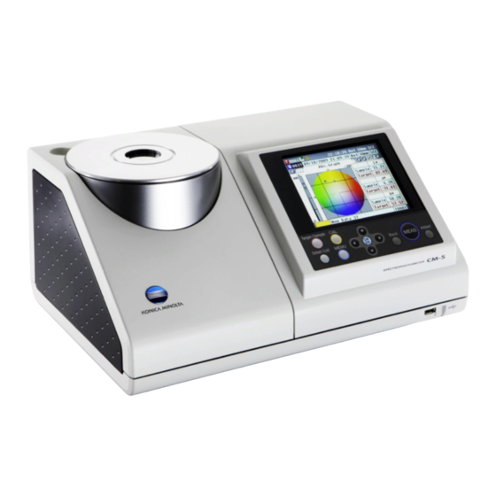
- Page 1 Spectrophotometer CM-5 Instruction Manual Please read before using the instrument.
-
Page 2: Safety Symbols
• Every effort has been made in the preparation of this manual to ensure the accuracy of its contents. • However, should you have any questions or find any errors, please contact your retailer or a KONICA MINOLTA- authorized service facility. -
Page 3: Safety Precautions
Should liquid or metal adapter other than those specified by objects enter the instrument, turn the KONICA MINOLTA is used, it may result power OFF immediately, disconnect the in damage to the unit, fire or electric AC adapter plug from the AC outlet, and shock. -
Page 4: Introduction
Be sure to use the instrument within this range. Do not use it in areas of rapid temperature changes. • Do not leave the CM-5 in direct sunlight or near sources of heat, such as stoves etc. The internal temperature of the instrument may become much higher than the ambient temperature in such cases. - Page 5 Power Source • Make sure that the power switch is set to OFF (“”) when the CM-5 is not in use. • This instrument can be powered from the AC adapter (AC-A305). • Always use the AC adapter supplied as a standard accessory (AC-A305) and connect it to an AC outlet of the rated voltage and frequency.
-
Page 6: Notes On Storage
Notes on Storage • The CM-5 should be stored at temperatures between 0°C and 40°C, and at a relative humidity of 80% or less (35°C) without condensation.Do not store the instrument in areas subject to high temperatures, high humidity, sudden changes in temperature, or where freezing or condensation may occur, because these circumstances may cause a breakdown.It is recommended to store the CM-5 with a drying agent at a temperature around... -
Page 8: Table Of Contents
Connecting the Functional Ground Cable .................. 19 Connecting the AC Adapter ......................20 Turning power ON/OFF ......................20 Items You Must Know ........................21 Initial Settings of the CM-5 ......................21 Control Panel ..........................21 Data Saving ..........................25 Chapter 2 - Preparation for Measurement Flow of Measurement ........................ - Page 9 Chapter 3 - Measurement Measurement ..........................112 Displaying the Measurement Results ..................113 <Sample> Detail Screen: Absolute ...................113 <Sample> Detail Screen: “Difference” Tab ................114 <Sample> Detail Screen: “Abs. & Diff.” Tab ................114 <Sample> Detail Screen: “Custom” Tab ..................115 <Sample> Detail Screen: “Abs.Graph” Tab ................115 <Sample>...
-
Page 10: Conventions
Conventions This manual describes how to safely operate the CM-5 using a specific procedure to perform measurement. • Page layout Symbols used in this manual are explained below. * Note that the page shown in the illustration is for explanatory purposes only, and is not an actual page from this manual. -
Page 11: Chapter 1 - Before Using The Instrument
Chapter 1 Before Using the Instrument... -
Page 12: Accessories
Accessories Standard and optional accessories are available with the instrument. Memo The shape of some products may be different from those shown. Standard Accessories Make sure that all the following items are present. Target Mask: ø30 mm CM-A197 During reflectance measurement, this target mask can be replaced with the optional target mask (ø3 mm or ø8 mm) to change the illumination area (specimen measuring port size) according to the specimen. -
Page 13: Optional Accessories
Optional Accessories You may purchase the following accessories if necessary. Petri Dish Measurement Full Set CM-A205 Target Mask (for Petri Dish): Calibration Glass Petri Dish: CM-A128 CM-A203 (for Petri Dish): CM-A212 Used to perform reflectance Used for calibration for reflectance measurement using a Petri Dish. - Page 14 Transmittance Measurement Set CM-A206 Transmittance Zero Calibration Transmittance Specimen Holder Accessory Case: CM-A193 Plate: CM-A213 Attachment: CM-A199 A light-shielding plate used for zero Used to attach the transmittance calibration for transmittance specimen holder to the receiving measurement. window side. Transmittance Specimen Holder: CM-A96 10 mm Wide Cell Measurement Set CM-A207 Transmittance Specimen Holder (10 mm wide): CM-A198...
- Page 15 Target Mask Target Mask: ø3 mm Target Mask: ø8 mm CM-A195 CM-A196 Used to switch the illumination area (specimen measuring port size) according to the specimen. Cell Cell: 2 mm Cell: 10 mm Cell: 20 mm CM-A97 CM-A98 CM-A99 A glass container to contain the liquid specimen during transmittance measurement. Plastic Cell Plastic Cell: 2 mm Plastic Cell: 10 mm...
-
Page 16: System Diagram
AC Adapter AC-A305 Target Mask: ø8 mm CM-A196 Target Mask: ø30 mm CM-A197 USB Cable (2 m) IF-A19 Spectrophotometer Dust Cover CM-5 CM-A191 Personal computer (commercially available) USB Memory (commercially available) Transmittance Measurement / Petri Dish Measurement Full Set CM-A214... -
Page 17: Names And Functions Of Parts
Names and Functions of Parts 12 13... - Page 18 LCD screen Displays setting items, measurement results and messages. Control panel Used to switch screens or select/determine/save setting items. For details, refer to page 23 “Control Buttons”. Specimen measuring port The port for measuring the specimen. The port size can be changed by changing the Target Masks.
-
Page 19: Cleaning Parts
Cleaning Parts This section explains how to clean the Target Mask, White Calibration Plate, Zero Calibration Box, and the inside of the integrating sphere. Target Mask and Transmittance Mask (Standard/optional accessory) Use a blower to remove dirt and dust from the Target Masks. Notes Do not touch the inside (edge) of the Target Mask with your Edge... - Page 20 Do not touch the white-coated inner surface of the Notes integrating sphere, wipe it with a cloth or put an object inside Shutter it. If the inside is so dirty that dirt cannot be removed with a blower, contact the nearest KONICA MINOLTA-authorized service facility.
-
Page 21: Connecting The Functional Ground Cable
Receiving window of the Transmittance Specimen Chamber 1. Set measuring diameter to ø3 mm. For the procedure for switching measuring diameter, refer to Memo page 61 “Measurement Area”. 2. Use a blower to remove dirt and dust from the receiving Receiving window. -
Page 22: Connecting The Ac Adapter
Connecting the AC Adapter Notes • To supply AC power to the instrument, always use the AC adapter (AC-A305) supplied with the instrument. • Before connecting or disconnecting the AC adapter jack or plug, make sure that the instrument is turned OFF. [Procedure] 1. -
Page 23: Items You Must Know
For details, refer to page 93 “Other Settings”. Control Panel The front of the CM-5 contains the LCD screen on which the instrument displays measurement results and messages, and the control buttons which are used to set measurement options or to change displays. - Page 24 Status Bar Display Description (Status) Meaning Active Target number Target number currently set in the instrument/ xxxx / Auto Auto Target set to ON Calibrating Zero Calibration / White Calibration / User / None Calibration not performed or Calibration is complete Flash ready Measurement possible or not possible...
- Page 25 Control Buttons Use these buttons to set items or change screens according to the guide on the LCD screen. [Target/Sample] button Switches between <Target> screen and <Sample> screen. [Detail/List] button When the <Sample> or <Target> screen is displayed, use this button to switch between the detail display and list display.
- Page 26 The screen will change depending on the button operation. <Measurement Condition <Configuration> screen Settings> screen <Sample> screen <Sample Data Function> <Sample> detail screen <Sample> list screen screen <Target> screen <Target> detail screen <Target> list screen <Target Data Function> screen...
-
Page 27: Data Saving
Data Saving Data used with this instrument are saved automatically. -
Page 29: Chapter 2 - Preparation For Measurement
Chapter 2 Preparation for Measurement... -
Page 30: Flow Of Measurement
Flow of Measurement nOptional settings nBasic procedure Turning power ON (Page 20) Language selection (Page 104) * As necessary (after initialization, etc.) Condition settings (Page 59) * When required depending on the Target Mask replacement, etc. (Page 42) measurement conditions Zero calibration (0% Calibration) * Only when required (Page 52) -
Page 31: Quick Setting Wizard
Quick Setting Wizard When you use the instrument for the first time, you can set the measurement conditions and calibrate the instrument step by step by following the instructions on the screen. [Procedure] Turn the instrument ON. The <Welcome to Easy Setup Wizard!> screen appears after the initial screen. - Page 32 <Reflectance measurement> 4. Use the button of the cross key to move the cursor to “Reflectance” and then press the [OK/Edit] button. The cursor moves to “Next”. 5. Press the [OK/Edit] button. The <Measurement Area Selection> screen appears. Use the button of the cross key to move the cursor to the desired measurement area and then press...
- Page 33 Check that the cursor is on “Next”, and press the [OK/Edit] button. The <Zero Calibration> screen Memo appears. Since the CM-5 stores the data The following is the explanation when of the zero calibration zero calibration will be skipped. performed at the factory, it is...
- Page 34 When the white calibration is completed, Memo the <Auto White Cal. Selection> Automatic white calibration is screen appears. convenient if measurements are almost always performed Settings: without changing the measurement type or other “Automatic”: White calibration will be measurement conditions each performed automatically immediately time.
- Page 35 To save the condition file: Verify that a USB memory device is connected. button of the cross key Use the to move the cursor to and press the [OK/Edit] button. After the condition file has been saved, the <Meas. Cond. Settings completed> screen appears.
- Page 36 Check that the cursor is on “Next”, and press the [OK/Edit] button. The <Zero Calibration> screen Memo appears. Since the CM-5 stores the data The following is the explanation when of the zero calibration zero calibration will be skipped. performed at the factory, it is...
- Page 37 When the white calibration is completed, Memo the <Auto White Cal. Selection> Automatic white calibration is screen appears. convenient if measurements are almost always performed Settings: without changing the measurement type or other “Automatic”: White calibration will be measurement conditions each performed automatically immediately time.
- Page 38 To save the condition file: Verify that a USB memory device is connected. Use the button of the cross key to move the cursor to and press the [OK/Edit] button. After the condition file has been saved, the <Meas. Cond. Settings completed> screen appears.
- Page 39 Check that the cursor is on “Next”, and press the [OK/Edit] button. The <0% Calibration> screen appears. Memo Since the CM-5 stores the data The following is the explanation when of the 0% calibration 0% calibration will be skipped. performed at the factory, it is...
- Page 40 When the 100% calibration is Memo completed, the <Auto 100% Cal. For details of 100% Selection> screen appears. calibration, refer to page 55. Settings: “Automatic”: 100% calibration will be performed automatically immediately after instrument is switched on. “Manual”: 100% calibration must be performed manually before taking measurements.
- Page 41 Check that the cursor is on “Next”, and press the [OK/Edit] button. The <0% Calibration> screen appears. Memo Since the CM-5 stores the data The following is the explanation when of the 0% calibration zero calibration will be skipped. performed at the factory, it is...
- Page 42 The <100% Calibration> screen Memo Cell or appears. For details of 100% Plastic Cell Light calibration, refer to page Place a specimen for 100% calibration (a container containing a liquid with high transmittance such as distilled water) in the Transmittance Specimen Chamber 10.
- Page 43 To save the condition file: Memo Verify that a USB memory device is The USB memory device must connected. be connected to the instrument button of the cross key Use the before saving the condition file to move the cursor to and press the to a USB memory device.
-
Page 44: Setting A Specimen
Setting a specimen Reflectance measurement To use the instrument for reflectance measurement of specimens other than powder or paste, attach the Target Mask to the specimen measuring port and set a specimen on it. The Target Mask can be selected from three types based on the illumination area (specimen measuring port size): ø30 mm, ø8 mm and ø3 mm, depending on the specimen and application. -
Page 45: Petri Dish/Mini Petri Dish Measurements
Petri Dish/Mini Petri Dish measurements Use a Petri Dish or Mini Petri Dish to allow the instrument to measure the reflectance of powder or paste specimens. The Mini Petri Dish enables measurements with much smaller amounts of specimens. When taking reflectance measurements, make sure that there is no object in the transmittance specimen chamber. Notes Required accessory Petri Dish Measurement Set CM-A205 (Optional) - Page 46 Notes Be careful that the bottom of the Petri Dish or Mini Petri Dish or the Calibration Glass (for Petri Dish) or Calibration Glass (for Mini Petri Dish) does not get scratched or stained, or get fingerprints on it. If it becomes dirty, wipe it with a soft, clean dry cloth.
- Page 47 Attaching the Target Mask to the instrument 1. Align the Target Mask (for Petri Dish) or Target Mask Target Mask (for (for Mini Petri Dish) with the positioning groove on the Petri Dish) CM-A203 instrument and push the mask in. Although automatic zero and white calibration can be performed when using the Petri Dish or Mini Petri Dish and Notes are sufficient for relative measurements comparing samples with a target, for the highest accuracy, zero calibration...
- Page 48 <To measure a specimen> 2. When using the Petri Dish: Insert the Petri Dish Petri Dish containing a specimen into the recess in the Target CM-A128 Mask (for Petri Dish). When using the Mini Petri Dish: Insert the Mini Petri Dish containing a specimen into the recess in the Target Mask (for Mini Petri Dish).
-
Page 49: Specimen Viewing Mirror (Optional)
Specimen Viewing Mirror (Optional) The Specimen Viewing Mirror allows you to check the measurement points for a specimen when using the instrument for reflectance measurement. How to use the Specimen Viewing Mirror 1. Place a specimen on the Target Mask. Specimen 2. -
Page 50: Transmittance Measurement And Liquid Measurement
Transmittance Measurement and Liquid Measurement To use the instrument for transmittance measurement, attach the Transmittance Mask on the illumination window of the Transmittance Specimen Chamber and then set a specimen. The Transmittance Measurement Set allows you to set a container containing a liquid specimen or a specimen in the form of plate or film easily and reliably. - Page 51 Attaching the Transmittance Specimen Holder to the instrument • Do not spill a specimen or other liquid on the instrument. Doing so may cause malfunction. If any liquid is Notes spilled on the instrument, wipe it off immediately with a soft, dry cloth. •...
- Page 52 Setting a film specimen Water drops formed on a specimen due to condensation or other causes prevent accurate measurement. Notes 1. Open the specimen fixing plate and secure a specimen Illumination with the plate. window When setting the specimen on the illumination window Notes side, position it so that it fully covers the illumination window.
- Page 53 Measuring a liquid specimen by using a commercially-available 10 mm-wide cell • As for the container for a liquid specimen, use a colorless, transparent container with surfaces which make Notes parallel with the illumination window and receiving window of the instrument. •...
-
Page 54: Calibration
Calibration Zero Calibration (0% Calibration) Since the CM-5 stores the data of the zero calibration (0% Calibration) performed at the factory, it is unnecessary to repeat the zero calibration (0% Calibration) every time you turn ON the instrument. If, however, the measurement conditions change greatly, or if the optional Target Mask (ø8 mm or ø3 mm), Petri Dish, Mini... - Page 55 <Reflectance measurement> 3. Clear an area of 1 m radius from the specimen measuring port of the instrument. Keep everything including light sources (such as fluorescent Within 1 m lamps and other illumination) and reflective items (hands, desks, walls etc.) more than 1 m away from the specimen measuring port.
- Page 56 <Transmittance measurement> 3. Open the Transmittance Specimen Chamber Cover and set the Transmittance Zero Calibration Plate so that it fully covers the illumination window. Notes Set the Transmittance Zero Calibration Plate horizontally, as shown to the right. If the Transmittance Zero Calibration Plate is set vertically, the Transmittance Specimen Transmittance Chamber Cover may not close.
-
Page 57: White Calibration (100% Calibration)
White Calibration (100% Calibration) White calibration (100% Calibration) must be performed prior to start of measurement after the power is turned ON for the first time after purchase at the current settings. • The built-in White Calibration Plate of the instrument is provided with its own calibration data. Memo •... - Page 58 <Reflectance measurement> 3. Press the [OK/Edit] button. White calibration is performed by using the built-in White Calibration Plate of the instrument. The Xe lamp flashes three times during the calibration. During white calibration, the screen shows the number of flashes performed. When the white calibration is completed, the screen returns to the one displayed before the <Measurement Condition Settings>...
- Page 59 <Transmittance measurement> 3. Open the Transmittance Specimen Chamber Cover and empty the space between the illumination and receiving windows. (No specimen, cell or Zero Calibration Plate being set.) 100% calibration can be performed with the Transmittance Notes Specimen Holder installed. 4.
-
Page 60: User Calibration
User Calibration You can perform calibration by using your own reference plate and calibration data instead of the white calibration (100% calibration) data. The calibration data for user calibration can be specified by connecting the instrument to a PC and using the optional Color Management Software “SpectraMagic™ NX”. You can select whether to use the user calibration data for measurement on the <Calibration Option Setting>... -
Page 61: Condition Setting
Condition Setting The CM-5 requires condition settings (measurement condition, measurement option, and color) before measurement can be started. To configure condition settings, select “Meas. Condition” (measurement conditions), “Meas. Option” (measurement Memo options) or “Color” (display conditions) from the <Configuration> screen to open an appropriate screen. - Page 62 Measurement Type Select the measurement type such as reflectance measurement or transmittance measurement. [Setting Procedure] Start the procedure from the <Measurement Condition Settings> screen. 1. Use the button of the cross key to move the cursor to “Meas. Type” and then press the [OK/Edit] button.
- Page 63 Measurement Area When the measurement type is Reflectance or Petri Dish, select the measurement area. [Setting Procedure] Start the procedure from the <Measurement Condition Settings> screen. 1. Use the button of the cross key to move the cursor to “Meas. Area” and then press the [OK/Edit] button.
- Page 64 Specular Component (SCI/SCE) When the measurement type is reflectance measurement, select the specular component mode. When the Petri Dish measurement is selected, “SCE” is set automatically. [Setting Procedure] Start the procedure from the <Measurement Condition Settings> screen. 1. Use the button of the cross key to move the cursor to “SCI/SCE”...
-
Page 65: Measurement Option Settings
Measurement Option Settings To set measurement options, select “Measurement Options” from the <Configuration> screen. You can select or specify the following three items as the measurement options: • Auto Measurement (1-10): Specify the number of measurements for auto averaging. • Manual Measurement (1-30): Specify the number of measurements for manual averaging. •... - Page 66 Auto Measurement (1-10) Specify the number of measurements for auto averaging. The average of the data obtained from the specified number of continuous measurements is determined as sample data. [Setting Procedure] Start the procedure from the <Measurement Options> screen. 1. Use the button of the cross key to move the cursor to “Auto Measurement (1-10)”...
- Page 67 Manual Measurement (1-30) Specify the number of measurements for manual averaging. The average of the data obtained from the measurements conducted with the presses of the [MEAS] button for the specified number of times is determined as sample data. [Setting Procedure] Start the procedure from the <Measurement Options>...
- Page 68 Shutter Open/Close When cleaning the inside of the integrating sphere or to check the measurement points for a specimen using the Specimen Viewing Mirror (Optional), you need to open or close the shutter of the specimen measuring port. Use this option for the open/close operation. During measurement, the shutter is automatically opened or closed according to the measurement type.
-
Page 69: Setting The Display Conditions
Setting the Display Conditions To set display conditions, select “Color” from the <Configuration> screen. You can select or specify the following five items as the display conditions: • Color Space: Select the color space to be displayed. • Color Index: Select the index (WI, YI, etc.) to display. •... - Page 70 Color Space Select the color space to be used or the index used for transmittance measurement. [Setting Procedure] Start the procedure from the <Color Settings> screen. 1. Use the button of the cross key to move the cursor to the desired “Color Space” and then press the [OK/Edit] button.
- Page 71 3. Press the [OK/Edit] button. If you select L*a*b* or L*C*h, <Difference Formula Settings> screen is displayed. If you select Ph. EU, <Ph.EU Hue setting> screen is displayed. If you select options other than above, the selection is confirmed and the screen returns to the <Color Settings> screen.
- Page 72 Color Index Select the index (WI, YI, etc.) to be used. This screen is available when the user index has been set with the optional Color Management Software SpectraMagic™ NX (CM-S100w) in advance. [Setting Procedure] Start the procedure from the <Color Settings> screen. 1.
- Page 73 3. Press the [OK/Edit] button. The selection is confirmed and the screen returns to the <Color Settings> screen. If you press the [Back] button without pressing the [OK/ Notes Edit] button, you return to the <Color Settings> screen without changing the setting.
- Page 74 Observer Select the observer angle: 2° or 10°. [Setting Procedure] Start the procedure from the <Color Settings> screen. 1. Use the button of the cross key to move the cursor to the desired “Observer” and then press the [OK/Edit] button. The <Observer Settings>...
- Page 75 Illuminant 1 Select the illuminant used to measure colorimetric data. [Setting Procedure] Start the procedure from the <Color Settings> screen. 1. Use the button of the cross key to move the cursor to the desired “Illuminant 1” and then press the [OK/Edit] button.
- Page 76 3. Press the [OK/Edit] button. The selection is confirmed and the screen returns to the <Color Settings> screen. If you press the [Back] button without pressing the [OK/ Notes Edit] button, you return to the <Color Settings> screen without changing the setting.
- Page 77 Illuminant 2 Select the secondary illuminant used for MI (metamerism index) calculation, etc. [Setting Procedure] Start the procedure from the <Color Settings> screen. 1. Use the button of the cross key to move the cursor to the desired “Illuminant 2” and then press the [OK/Edit] button.
-
Page 78: Color Difference Target Color Data Operation
To measure the color difference between two specimens, the color of one of the specimens must be set as the target color. The CM-5 can store up to 1,000 target colors. When using the instrument alone, measure a target specimen by following the procedure below and set the result as the target color. - Page 79 4. Make sure that (Ready to measure) is displayed or the Ready lamp is green, and then press the measuring button. The specimen is measured and the result is displayed on the screen. If you selected a number to which target color data has Notes already been set, a message is displayed to confirm overwriting.
-
Page 80: Editing Target Color Data
Editing Target Color Data The <Target Data Function> screen allows the following operations for target color data. “Current” tab • Save: Saves the current target color data to a USB memory device. • Statistics: Performs statistical calculations using multiple target color data selected in a list screen. •... - Page 81 Saving the Current Target Color Data to a USB Memory Device Save the current target color data to a USB memory device. You will need to connect a USB memory device to the instrument in advance. For information on connecting a USB memory device, refer to page 141 “Connecting a USB Memory”.
- Page 82 5. When you are finished entering Memo characters, press [MENU] button, The USB memory device must move the cursor to “Save” and then be connected to the instrument press the [OK/Edit] button. before saving the condition file The settings are confirmed and the screen to a USB memory device.
- Page 83 The <Target List> screen will appear. 3. Use the button of the cross key to select a target to use for statistical calculations and then press the [OK/Edit] button to confirm the selection. • A check mark will appear in the box to the left of the target name when a target is selected.
- Page 84 4. After all desired targets have been selected, use the button of the cross key to move the cursor to the “OK” button and then press the [OK/Edit] button. The <Statistic calculation> screen will appear. • To save the average of the data, use the button of the cross key to move the cursor to the [Save] button and press the [OK/Edit] button.
- Page 85 Edit Name Name the target color data. [Procedure] Start the procedure from the <Target Data Function> screen. 1. Use the button of the cross key to select the “Current” tab, use the button to move the cursor to “Edit Name”, and then press the [OK/Edit] button.
- Page 86 If you press the [Back] button during the setting, “Do you Memo want to save the changes?” is displayed. When you place the cursor on “OK” and press the [OK/Edit] button, the setting details are confirmed and the screen returns to the <Target>...
- Page 87 Tolerance Setting Specify the tolerance used for pass/fail judgment of measured data for each target color. • Before tolerance is specified for individual target colors, the instrument is set with default tolerance. For details, Memo refer to page 89 “Default Tolerance Setting”. •...
- Page 88 4. When you finish all settings, press the button or [MENU] button of the cross key to move the cursor on “Save”, and then press the [OK/Edit] button. The setting is confirmed and the screen returns to the <Target Data Function> screen. If you press the [Back] button during the setting, the Memo <Save Confirmation>...
- Page 89 Save to USB memory device Save all target color data stored in the instrument to the USB memory device. The USB memory device must be connected to the instrument before saving the data. For the connection of a USB memory device, refer to page 141 “Connecting a USB Memory”. A USB keyboard can also be used to input file names.
- Page 90 5. Use buttons of the cross key to move the cursor around the characters and then press the [OK/Edit] button. The selected character is displayed in the text box. 6. Repeat Step 5 until you enter necessary characters. • You can use the button of the cross key to move the blue box cursor on the text box.
- Page 91 Default Tolerance Setting This instrument allows tolerance setting for individual target color data. Before setting such individual tolerance, the instrument is set with default tolerance. This section describes the procedure to set default tolerance. • Before tolerance is specified for individual target colors, the instrument is set with default tolerance. Memo •...
- Page 92 4. When you finish all settings, press the button or [MENU] button of the cross key to move the cursor on “Save”, and then press the [OK/Edit] button. The setting is confirmed and the screen returns to the <Target Data Function> screen. If you press the [Back] button during the setting, the Memo <Save Confirmation>...
- Page 93 Data Protection You can specify data protection so that the saved target color setting will not be deleted or changed by accident. When the data protection is set, you cannot select “Edit Name”, “Tolerance”, “Delete”, “Statistic calculation” and “Delete All” on the <Target Data Function> screen. [Setting Procedure] Start the procedure from the <Target Data Function>...
- Page 94 Delete All Delete all the target color data which have been set. When the data is protected, you cannot select “Delete All” on the <Target Data Function> screen. Notes [Setting Procedure] Start the procedure from the <Target Data Function> screen. 1.
-
Page 95: Other Settings
Other Settings Setting Automatic White Calibration (100% Calibration) to ON/OFF Set whether to perform white calibration (100% Calibration) automatically when the power switch of the instrument is set to ON. [Setting Procedure] 1. Press the [MENU] button. The <Configuration> screen is displayed. 2. - Page 96 4. Use the button of the cross key to move the cursor to the desired item. Settings OFF : Disable automatic white calibration (100% Calibration) the next time the instrument is turned ON (the power switch is set to ON). ...
-
Page 97: Setting The Measurement Result Display
Setting the Measurement Result Display To set details about the measurement result display, select “Graph” from the <Configuration> screen. [Setting Procedure] 1. Press the [MENU] button. The <Configuration> screen is displayed. 2. Use the button of the cross key to move the cursor to “Graph”... - Page 98 Setting the Custom Data Screen to ON/OFF The measurement result display function allows you to switch between various screens including “Absolute” or “Difference”. You can add the “Custom Data” screen showing your desired items to these screens. This section describes the procedure to set whether to display this “Custom Data” screen. To set the items displayed on the “Custom”...
- Page 99 5. Press the [Back] button. The screen returns to the <Graph and Data Settings> screen. Setting the Assess. Graph Screen to ON/OFF The measurement result display function allows you to switch between various screens including “Absolute” or “Difference”. You can add the “Assess. Graph” screen based on tone data to these screens. This section describes the procedure to set whether to display this “Assess.
- Page 100 4. Press the [OK/Edit] button. The selection is confirmed and the screen returns to the <Color Assessment Settings> screen. If you press the [Back] button without pressing the [OK/ Notes Edit] button, you return to the <Color Assessment Settings> screen without changing the setting. 5.
- Page 101 3. Use the button of the cross key to move the cursor to the desired item. Settings Reflectance/Transmittance: “Spectral” screen shows reflectance (or transmittance) graph without reflectance (or transmittance) data at selected wavelengths. Absorbance: “Spectral” screen shows absorbance graph without absorbance data at selected wavelengths.
- Page 102 7. Press the [OK/Edit] button. The selection is confirmed and the screen returns to the <Spectral Graph Settings> screen. If you press the [Back] button without pressing the [OK/ Notes Edit] button, you return to the <Spectral Graph Settings> screen without changing the setting. 8.
-
Page 103: Setting The Screen Options
Setting the Screen Options To set screen options, select “Screen Option” from the <Configuration> screen. [Setting Procedure] 1. Press the [MENU] button. The <Configuration> screen is displayed. 2. Use the button of the cross key to move the cursor to “Screen Option” and then press the [OK/Edit] button. - Page 104 Setting the Quick Setting Wizard Display to ON/OFF When the power switch of the instrument is set to ON, the <Welcome to Easy Setup Wizard!> screen is normally displayed and you can set the measurement conditions and calibrate the instrument step by step by following the instructions on the screen.
- Page 105 Setting the LCD Brightness The brightness of the LCD can be set in five levels. Selecting a darker level is effective for power saving. The brightness level is factory-set to “3 (Standard)”. Memo [Setting Procedure] Start the procedure from the <Screen Option Settings> screen. 1.
- Page 106 Setting the Display Language The display language can be changed from the factory-set language. Available languages are: English, Japanese, German, French, Spanish, Italian, Chinese, and Portuguese. The language is factory-set to “English”. Memo When the backup battery of the instrument has gone dead, the display language is reset to “English” regardless of Notes the factory-set language.
-
Page 107: Setting The Date And Time
Setting the Date and Time To set date and time, select “System” from the <Configuration> screen. [Setting Procedure] 1. Press the [MENU] button. The <Configuration> screen is displayed. 2. Use the button of the cross key to move the cursor to “System” and then press the [OK/Edit] button. - Page 108 2. Use the button of the cross key to move the cursor to a desired item and then press the [OK/Edit] button. The cursor color turns to blue and ▲ and ▼ are displayed above and below the cursor. 3. Use the button of the cross key to change the value.
- Page 109 Setting the Date Format You can change the format of the date displayed on the screen. [Setting Procedure] Start the procedure from the <System Settings> screen. 1. Use the button of the cross key to move the cursor to “Date Format” and then press the [OK/Edit] button.
-
Page 110: Batch Setting Of Conditions
Batch Setting of Conditions You can save various conditions (display conditions, measurement conditions, etc.) as a file in advance and set the conditions of the instrument all at once by loading the file. [Preparation] 1. Press the [MENU] button. The <Configuration> screen is displayed. 2. - Page 111 5. Use the buttons of the cross key to move the cursor around the characters and then press the [OK/Edit] button. The selected character is displayed in the text box. 6. Repeat Step 5 until you have entered the necessary characters.
-
Page 112: Chapter 3 - Measurement
<Measurement Condition Settings> screen “Meas. Type”, “Meas. Area”, “SCI/SCE” <Measurement Options> screen “Auto Measurement (1-10)”, “Manual Measurement (1-30)” <Color Settings> screen “Color Space”, “Color Index”, “Observer”, “Illuminant 1”, “Illuminant 2” <Calibration Option Settings> screen “Calibration Data” <Graph and Data Settings> screen “Custom Data View Settings”, “Color Assessment Settings”... - Page 113 Chapter 3 Measurement E111...
-
Page 114: Measurement
Measurement • Prior to the start of measurement, be sure to perform white calibration (100% calibration). For details, refer to Notes page 55 “White Calibration (100% Calibration)”. • To display the color difference, it is necessary to set target colors before measurement. •... -
Page 115: Displaying The Measurement Results
Displaying the Measurement Results At the end of measurement, the measurement results will be displayed on the LCD according to the specified conditions. Typical measurement result screens are shown below. Notes Measurement results cannot be switched when “Communicating” is displayed while the instrument is connected to a PC. -
Page 116: Sample> Detail Screen: "Difference" Tab
<Sample> Detail Screen: “Difference” Tab 18 Sample data (The tab can be switched with the button of the cross key.) Any color difference value which failed the pass/fail judgment based on the color difference tolerance will be highlighted in red. ... -
Page 117: Sample> Detail Screen: "Custom" Tab
<Sample> Detail Screen: “Custom” Tab 18 Sample data (The tab can be switched with the button of the cross key.) • This tab is displayed when the “Show Custom Data Screen” is set to ON. For the procedure of the “Show Custom Data Screen”... -
Page 118: Sample> Detail Screen: "Diff.graph" Tab
<Sample> Detail Screen: “Diff.Graph” Tab button of the cross key.) 18 Sample data (The tab can be switched with the ΔL* axis (color difference graph) Δa* axis (color difference graph) ... -
Page 119: Sample> Detail Screen: "Assess.graph" Tab
<Sample> Detail Screen: “Assess.Graph” Tab 18 Sample data (The tab can be switched with the button of the cross key.) Lightness axis Chroma axis Hue axis Scales for the axes ... -
Page 120: Sample> Detail Screen: "Spectral" Tab
<Sample> Detail Screen: “Spectral” Tab button of the cross key.) 18 Sample data (The tab can be switched with the Axis of spectral reflectance Axis of spectral reflectance difference ... -
Page 121: Sample> List Screen
<Sample> List Screen Every time the [Detail/List] button is pressed, the screen is switched between the <Sample> detail screen and <Sample> list screen. Measurement can be performed on either the <Sample> detail screen or <Sample> list screen. Memo 10 Sample data No. 11 Date and time of the measurement 12 Measurement type used for the measurement (Ref: Reflectance measurement, Tra: Transmittance measurement, Pet: Petri Dish measurement, Liq: Liquid measurement) -
Page 122: Switching The Display Contents Of The Measurement Results
Switching the Display Contents of the Measurement Results The contents of the measurement result display can be changed by pressing the button of the cross key on the <Sample> detail screen. The contents to be displayed will vary depending on the setting. Notes Measurement results cannot be switched when “Communicating”... - Page 123 Table legend : The tab is displayed. × : The tab is displayed, but no item will be displayed. : The tab is not displayed. 2 “Difference” tab 8 “Spectral” tab “Abs. & “Custom” “Abs.Graph” “Diff.Graph” “Assess. Color Spectral Diff.”...
-
Page 124: Sample Data Operation
Sample Data Operation On the <Sample Data Function> screen, the following operations are available for the sample data. “Current” tab • Save : Saves the current sample data to a USB memory device. • Statistics : Performs statistical calculations using multiple samples selected in a list screen. •... -
Page 125: Saving The Current Sample Data To A Usb Memory Device
Saving the Current Sample Data to a USB Memory Device Save the current sample data to a USB memory device. The USB memory device must be connected to the instrument before saving the data. For information on connecting a USB memory device, refer to page 141 “Connecting a USB Memory”. Start the procedure from the <Sample Data Function>... - Page 126 6. When you are finished entering characters, press [MENU] button, move the cursor to “Save” and then press the [OK/Edit] button. The settings are confirmed and the screen returns to the <Save Sample Data> screen. • If you press the [Back] button during the setting, “Do Memo you want to save the changes?”...
-
Page 127: Performing Statistical Calculations On Sample Data
Performing Statistical Calculations on Sample Data Performs statistical data on sample data stored in the instrument. The data to be used for calculations can be selected in a list screen. After calculations have been performed, the average of the samples selected for statistical calculations can be saved as a new sample data. -
Page 128: Edit Name
Edit Name Name the sample data. [Operating Procedure] Start the procedure from the <Sample Data Function> screen. 1. Use the button of the cross key to select the “Current” tab, use the button to move the cursor to “Edit Name” and then press the [OK/Edit] button. -
Page 129: Print
Print Print the sample data. You need to connect the instrument to a serial printer in advance. For instructions on how to connect the instrument and a serial printer, refer to page 145 “Printer Connection”. • If proper connection is not established, you cannot print data. Notes •... -
Page 130: Delete
Delete Delete the sample data. [Operating Procedure] Start the procedure from the <Sample Data Functions> screen. 1. Use the button of the cross key to select the “Current” tab, use the or button to move the cursor to “Delete” and then press the [OK/Edit] button. The <Delete Sample Data>... -
Page 131: Sample=>Target
Sample=>Target Set sample data as target color data. [Operating Procedure] Start the procedure from the <Sample Data Function> screen. Unlike measured data, the numbers assigned to target color data do not change automatically. When you measure Notes colors continuously to set target colors, you need to move the cursor manually to set each data. 1. -
Page 132: Saving Data Onto A Usb Memory Device
Saving Data onto a USB Memory Device Save sample data stored in the instrument onto the USB memory device. You need to connect a USB memory device to the instrument in advance. For the connection of a USB memory device, refer to page 141 “Connecting a USB Memory”. [Operating Procedure] Start the procedure from the <Sample Data Function>... - Page 133 5. Use the buttons of the cross key to move the cursor around the characters and then press the [OK/Edit] button. The selected character is added to the text box. 6. Repeat Step 5 until you have entered the necessary characters.
-
Page 134: Auto Target
Auto Target Use this function to automatically select the target color with the smallest color difference (ΔE*ab) for measurement. The target color will be selected from those with the same specular component mode and other measurement Memo condition settings for the measurement. •... -
Page 135: Delete All
Delete All Delete all sample data. [Operating Procedure] Start the procedure from the <Sample Data Functions> screen. 1. Use the button of the cross key to select the “All” tab, use the button to move the cursor to “Delete All” and then press the [OK/Edit] button. The <Delete All Samples>... -
Page 136: Average Measurement
When taking measurements or setting target colors, more accurate data can be obtained if the averaging function is used. With the CM-5, the following two averaging functions are available. • Manual Measurement : When the color of the specimen is not uniform, measurements are performed randomly at different positions on the specimen and then the average of the measured spectral reflectance/transmittance data is calculated. - Page 137 3. Make sure that (Ready to measure) is displayed and then press the measuring button. The specimen is measured and the <Manual Average Measurement> screen is displayed. The <Manual Average Measurement> screen shows the result of the statistic calculation using the sample data of the measurements performed so far.
-
Page 138: Auto Measurement
Auto Measurement Measurement is repeated the specified number of times at the same position on the specimen and then the average of the measured spectral reflectance/transmittance data is calculated. This will improve the accuracy of the sample data. Before starting auto averaging, you must complete the settings for auto averaging. Notes For details, refer to page 64 “Auto Measurement”. -
Page 139: Chapter 4 - Other Functions
Chapter 4 Other Functions E137... -
Page 140: Pass/Fail Judgment For Color Difference
Pass/Fail Judgment for Color Difference With the CM-5, you can set tolerances for the color difference of the sample data from the target color data to make pass/fail judgment. For the procedure of setting tolerances, refer to page 85 “Tolerance Setting” and page 89 “Default Tolerance Setting”. - Page 141 3. On the <Target> detail screen, press the [OK/Edit] button. The <Target Data Function> screen is displayed. 4. Use the button of the cross key to select the “Current” tab, use the button to move the cursor to “Tolerance”, and then press the [OK/Edit] button.
- Page 142 <Sample> detail screen: “Difference” tab or “Abs. & Diff.” tab The values which failed the judgment are highlighted in red. In the print output to the printer, “X” is appended after the failed item. When at least one item failed the judgment, “Fail” is displayed;...
-
Page 143: Connecting To An External Device
Connecting to an External Device The instrument features two USB connection terminals, one for connecting a USB memory or a USB keyboard and one for connecting a PC, and an RS-232C connector. USB memory can be used for saving data or various conditions, and a USB keyboard can be used for text input when editing sample data names. - Page 144 2. Use the buttons of the cross key to move the cursor to “Output” and then press the [OK/ Edit] button. The <Output Settings> screen is displayed. 3. Use the button of the cross key to move the cursor to “USB Memory Stick Settings” and then press the [OK/Edit] button.
-
Page 145: Connecting A Usb Keyboard
Connecting a USB Keyboard On the <Sample Data Function> screen, a USB keyboard can be used for text input when editing sample data names. • Make sure that the USB keyboard is oriented correctly and connected securely. Notes • To connect the USB keyboard, check the shape of the receptacle (connection terminal) and insert the connector fully until it is secured. -
Page 146: Connecting A Personal Computer
(such as the optional Color Management Software SpectraMagic™ NX). • The USB communication port of the instrument conforms to USB 1.1. • To connect the instrument to a PC, you need to install the USB driver dedicated to the CM-5. Install the USB Notes driver supplied with the software that enables connection and operation of the instrument. -
Page 147: Printer Connection
Printer Connection By connecting the instrument to a serial printer with a connecting cable, you can print out the sample data and target color data stored in the memory of the instrument. You can use the “Automatic output” which prints data automatically for each measurement, or can print out the sample data and target color data currently displayed. - Page 148 Pin No.-Signal Connection Diagram for Printer Cable • For a D-sub 9-pin connector Printer side Instrument side (D-sub 9-pin connector) Pin No. Signal Signal Pin No. DATA BUSY • For a D-sub 25-pin connector Printer side Instrument side (D-sub 25-pin connector) Pin No.
- Page 149 3. Use the button of the cross key to move the cursor to “Serial Printer Settings” and then press the [OK/Edit] button. The <Serial Printer Settings> screen is displayed with a currently-specified baud rate. Other communication parameters cannot be changed. 4.
- Page 150 Printing Out Sample Data/Target Color Data Print the sample data or target color data with the printer. You need to connect the instrument to a serial printer in advance. Only text data can be output to a serial printer for printing. You cannot output the color difference graph or other Memo graphs displayed on the instrument.
- Page 151 2. Use the buttons of the cross key to move the cursor to “Output” and then press the [OK/ Edit] button. The <Output Settings> screen is displayed. 3. Use the button of the cross key to move the cursor to “Serial Printer Settings” and then press the [OK/Edit] button.
- Page 152 7. Press the [Back] button three times to return to the <Sample> screen. After measurement is performed on either of the <Sample> detail screen or <Target> detail screen, the <Print Sample Data> or <Print Target Data> screen is displayed and the data is printed from the connected printer.
- Page 153 • Print Example 4 <Sample> detail screen: “Custom” tab Absolute value, color difference and pass/fail judgment result specified for the custom screen • Print Example 5 Absolute value, color difference and pass/fail <Sample> detail screen: “Diff.Graph” tab judgment result • Print Example 6 Color difference, pass/fail judgment result <Sample>...
-
Page 154: System-Related Functions
System-related Functions Displaying the Instrument Information Display the model name, version and serial number of the instrument. [Operating Procedure] 1. Press the [MENU] button. The <Configuration> screen is displayed. 2. Use the buttons of the cross key to move the cursor to “System” and then press the [OK/ Edit] button. -
Page 155: Annual Service Recalibration Recommendation Message
When about one year passes after the factory shipment or the calibration service (or maintenance) conducted by KONICA MINOLTA-authorized service facility, the CM-5 shows a message “WR050 Time for Periodic Calibration. Please contact closest Service Center.” at start-up to recommend annual service recalibration. - Page 156 4. Use the button of the cross key to move the cursor to the desired item. Settings OFF: Do not show the annual service recommendation message when the specified day comes. ON: Show the annual service recommendation message when the specified day comes. 5.
-
Page 157: Initialization
Initialization Reset the settings of the instrument to the initial status. • Do not initialize the instrument unless necessary. Notes • The sample data, target color data, tolerances set to each target color and default tolerance settings will be protected and not be deleted by initialization. The sample data and target color data which you saved will be stored even after initialization. - Page 158 Initial Settings * Initialization of the instrument will reset the settings to the initial values shown in the table below. The sample data, target color data and the tolerances set for each target color are protected and not cleared by the initialization.
- Page 159 Item Initial setting Tolerance Color Space ΔL*, Δa*, Δb*, ΔC*, ΔH* Upper +1.5, ON limit * These are the Lower -1.5, ON factory-set limit values. ΔL, Δa, Δb, ΔX, ΔY, ΔZ Upper +1.5, OFF limit Initialization of the Lower -1.5, OFF instrument will not limit reset the settings to...
- Page 160 E158...
-
Page 161: Chapter 5 - Troubleshooting
Chapter 5 Troubleshooting E159... -
Page 162: Error Messages
The following messages may appear while you are using the instrument. If such messages appear, take the necessary actions shown in the table below. If the trouble does not go away in spite of taking the actions, contact a KONICA MINOLTA-authorized service facility. Notes The table below shows messages that may be displayed on the LCD of the instrument. - Page 163 Charge Circuit is not is not completed. and then perform measurement. If this message ready. • Breakdown of charging circuit keeps appearing, contact a KONICA MINOLTA- authorized service facility. ER031 • Faulty drive motor Confirm the switching operation between SCI Light Trap Error •...
- Page 164 Clean the integrating sphere as explained in Low Illumination. lamp has dropped to 50% of its “Cleaning Parts” on page 17. If the problem still initial level. remains, contact a KONICA MINOLTA- • Deterioration of xenon lamp authorized service facility. • Dirt on integrating sphere WR050...
-
Page 165: Troubleshooting
If an abnormality has occurred with the instrument, take necessary actions as given in the table below. If the instrument still does not work properly, turn the power OFF, and then turn it ON again. If the symptom remains, contact a KONICA MINOLTA-authorized service facility. Symptom... - Page 166 Symptom Check Point Action Measurement data or The instrument’s backup battery The backup battery has an expected service life settings are not held may be low immediately after of approximately ten years. If you find that the in memory, and purchase or following a period of instrument fails to retain data in memory even disappear...
-
Page 167: Chapter 6 - Appendix
Chapter 6 Appendix E165... -
Page 168: Principles Of Measurement
Principles of Measurement Illuminating/Viewing System <Objective color reflectance measurement> This instrument utilizes the di:8°/de:8° geometry conforming to CIE No. 15, ASTM E1164, DIN 5033 Teil 7, ISO 7724/1 and JIS Z 8722-1982 (diffused illumination, 8-degree viewing angle) standards, and offers measurement with automatic SCI (specular component included;... -
Page 169: Illumination Area And Measurement Area
<Object color transmittance measurement> This instrument utilizes the di:0 °/de:0 ° geometry conforming to CIE No. 15, ASTM E1164 and DIN 5033 Teil 7 standards, and offers measurement with SCI (specular component included) and SCE (specular component excluded) switching. The flow of measurement is shown below. 1. -
Page 170: Main Specifications
Inter-instrument (Based on 12 BCRA Series II color tiles compared to values measured with a master agreement body under Konica Minolta standard conditions) No sides (unlimited sample length); Depth (maximum sample thickness): 60 mm Transmittance Sample holders (optional) for holding sheet samples or containers of liquid samples... - Page 171 Spectrophotometer CM-5 Model Color-difference ΔE*ab (CIE 1976), ΔE*94 (CIE 1994), ΔE00 (CIE DE2000), ΔE (Hunter), CMC (l:c) equation Tolerances can be set to colorimetric values (except Munsell), color-difference values, Pass/Fail judgment or reflectance index values Data memory Measurement data: 4,000 measurements; Target color data: 1,000 measurements Storage of measurement data and target color data.
-
Page 172: Dimensions
Dimensions E170... - Page 173 < CAUTION > KONICA MINOLTA WILL NOT BE LIABLE FOR ANY DAMAGES RESULTING FROM THE MISUSE, MISHANDLING, UNAUTHORIZED MODIFICATION, ETC. OF THIS PRODUCT, OR FOR ANY INDIRECT OR INCIDENTAL DAMAGES (INCLUDING BUT NOT LIMITED TO LOSS OF BUSINESS PROFITS, INTERRUPTION OF BUSINESS, ETC.) DUE TO...
- Page 174 9222-A168-25 ©2009-2016 KONICA MINOLTA, INC. BGFAGA Printed in Japan...
Need help?
Do you have a question about the cm-5 and is the answer not in the manual?
Questions and answers
what is WR050?