Kyocera 300ci Service Manual
Kyocera 250ci; 300ci; 400ci; 500ci office mfp
Hide thumbs
Also See for 300ci:
- Service manual (587 pages) ,
- Operation manual (488 pages) ,
- Command reference manual (410 pages)

Related Manuals for Kyocera 300ci


Summary of Contents for Kyocera 300ci
-
Page 1: Service Manual
TASKalfa 250ci/300ci/ 400ci/500ci SERVICE MANUAL Published in July 2010 842H7116 2H7SM066 Rev. 6... - Page 2 CAUTION RISK OF EXPLOSION IF BATTERY IS REPLACED BY AN INCORRECT TYPE. DISPOSE OF USED BATTERIES ACCORDING TO THE INSTRUCTIONS. It may be illegal to dispose of this battery into the municipal waste stream. Check with your local solid waste officials for details in your area for proper disposal. ATTENTION IL Y A UN RISQUE D’EXPLOSION SI LA BATTERIE EST REMPLACEE PAR UN MODELE DE TYPE INCORRECT.
-
Page 3: Revision History
Revision history Revision Date Replaced pages Remarks November 26, 2008 CONTENTS, 1-1-2, 1-1-3, 1-2-2, 1-2-4, 1-2-5, 1-2-12 to 1-2-14, 1-2-16 to 22, 1-3-2 to 1-3-20, 1-3-25, 1-3-26, 1-3-30 to 1-3-34, 1-3-36, 1-3-37, 1-3-39 to 1-3-42, 1-3-45, 1-3-48 to 1-3-58, 1-3-60, 1-3-62 to 1-3-64, 1-3-66 to 1-3-76, 1-3-78 to 1-3-81, 1-3-83 to 1-3-88, 1-3-97, 1-3-100, 1-3-102, 1-3-103, 1-3-108, 1-3-109, 1-3-112 to 1-3-115, 1-3-119 to 1-3-131, 1-3-133, 1-3-136, 1-3-138, 1-3-139, 1-3-141 to 1-3-155,... - Page 4 This page is intentionally left blank.
-
Page 5: Safety Precautions
Safety precautions This booklet provides safety warnings and precautions for our service personnel to ensure the safety of their customers, their machines as well as themselves during maintenance activities. Service personnel are advised to read this booklet carefully to familiarize themselves with the warnings and precautions described here before engaging in maintenance activities. - Page 6 Safety warnings and precautions Various symbols are used to protect our service personnel and customers from physical danger and to prevent damage to their property. These symbols are described below: DANGER: High risk of serious bodily injury or death may result from insufficient attention to or incorrect compliance with warning messages using this symbol.
-
Page 7: Installation Precautions
1. Installation Precautions WARNING • Do not use a power supply with a voltage other than that specified. Avoid multiple connections to one outlet: they may cause fire or electric shock. When using an extension cable, always check that it is adequate for the rated current...................... •... - Page 8 2. Precautions for Maintenance WARNING • Always remove the power plug from the wall outlet before starting machine disassembly....• Always follow the procedures for maintenance described in the service manual and other related brochures............................• Under no circumstances attempt to bypass or disable safety features including safety mechanisms and protective circuits.
- Page 9 • Do not remove the ozone filter, if any, from the copier except for routine replacement....... • Do not pull on the AC power cord or connector wires on high-voltage components when removing them; always hold the plug itself......................•...
- Page 10 This page is intentionally left blank.
- Page 11 2JZ/2JX/2JV/2H7-5 CONTENTS 1-1 Specifications 1-1-1 Specifications............................1-1-1 1-1-2 Parts names............................1-1-4 (1) Body ..............................1-1-4 (2) Operation panel..........................1-1-7 1-1-3 Machine cross section ..........................1-1-8 1-2 Installation 1-2-1 Installation environment ..........................1-2-1 1-2-2 Unpacking and installation ........................1-2-2 (1) Installation procedure ........................1-2-2 (2) Setting initial copy modes........................1-2-13 1-2-3 Installing the key counter (option) ......................1-2-14 1-2-4 Installing the cassette heater (option) (inch specifications only)............1-2-23 1-3 Maintenance Mode...
-
Page 12: Table Of Contents
(1) Precautions ............................1-5-1 (2) Drum..............................1-5-1 (3) Toner ..............................1-5-1 (4) How to tell a genuine Kyocera Mita toner container................1-5-2 1-5-2 Paper feed section ..........................1-5-3 (1) Detaching and refitting the forwarding, paper feed and separation pulleys ........1-5-3 (2) Detaching and refitting the MP unit ....................1-5-6 (3) Detaching and refitting the MP forwarding, MP paper feed and MP separation pulleys ....1-5-8... - Page 13 2JZ/2JX/2JV/2H7-1 2-1-8 Duplex section ............................2-1-22 (1) Duplex section..........................2-1-22 2-2 Electrical Parts Layout 2-2-1 Electrical parts layout..........................2-2-1 (1) PWBs ..............................2-2-1 (2) Switches and sensors ........................2-2-4 (3) Motors ...............................2-2-6 (4) Others..............................2-2-8 2-3 Operation of the PWBs 2-3-1 Power source PWB..........................2-3-1 2-3-2 Engine PWB............................2-3-6 2-3-3 Main PWB .............................2-3-23 2-3-4 Main front PWB.............................2-3-33 2-3-5 Sub front PWB ............................2-3-37...
- Page 14 2JZ/2JX/2JV/2H7 This page is intentionally left blank.
-
Page 15: Specifications
2JZ/2JX/2JV/2H7-6 1-1 Specifications 1-1-1 Specifications Type ..........Desktop Printing system ....... Electrophotography by semiconductor laser, tandem drum system Supported original types ....Sheets, books and three-dimensional objects Maximum size: A3/Ledger Original feed system ....... Fixed Paper weight........Cassette: 60 - 163 g/m (Duplex: 60 - 163 g/m MP tray: 60 - 220 g/m Paper type ........ - Page 16 2JZ/2JX/2JV/2H7-5 Warm-up time ......... Room temperature 22 C/71.6 F, 60% RH 25/25, 30/30 ppm models Power on: 30 s or less Low power mode:30 s or less Sleep mode: 30 s or less 40/40, 50/40 ppm models Power on: 45 s or less Low power mode:30 s or less Sleep mode:...
- Page 17 2JZ/2JX/2JV/2H7-6 Printer functions Printing speed......... Same as copying speed First print time ......... 25/25, 30/30 ppm models 9.4 s or less (black and white)/10.9 s or less (full color) 40/40 ppm models 7.1 s or less (black and white)/8.1 s or less (full color) 50/40 ppm models 5.8 s or less (black and white)/8.1 s or less (full color) Resolution........
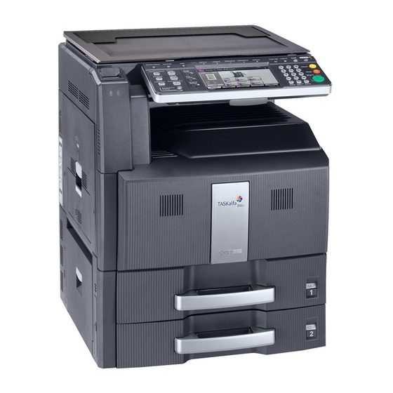
- Page 18 2JZ/2JX/2JV/2H7 1-1-2 Parts names (1) Body Figure 1-1-1 Original cover (option) Contact glass Original size indicator plates Slit glass Left cover 1 Left cover 1 indicator Left cover 1 lever Left cover 2 indicator Left cover 2 10. Left cover 3 11.
- Page 19 2JZ/2JX/2JV/2H7 Figure 1-1-2 19. Toner container release lever (Magenta) 20. Toner container (Magenta) 21. Toner container release lever (Cyan) 22. Toner container (Cyan) 23. Toner container release lever (Yellow) 24. Toner container (Yellow) 25. Toner container release lever (Black) 26. Toner container (Black) 27.
- Page 20 2JZ/2JX/2JV/2H7 Figure 1-1-3 31. Top tray 32. USB memory slot 33. Paper feed unit cover 34. Paper feed unit 35. Knob 36. Paper width adjusting tab 37. Paper length guide 38. Handles 39. MP tray (multi-purpose tray) 40. Paper width guide 41.
- Page 21 2JZ/2JX/2JV/2H7-2 (2) Operation panel 14 15 16 19 20 29 30 Figure 1-1-4 System menu key/indicator 16. Application key/indicator Counter key/indicator 17. Document box key/indicator Help key/indicator 18. Accessibility key/indicator Print indicator 19. Send key/indicator Send indicator 20. Copy key/indicator Receive indicator 21.
- Page 22 2JZ/2JX/2JV/2H7 1-1-3 Machine cross section Paper path Figure 1-1-5 Machine cross section Cassette paper feed section 10. Developing section (Yellow) MP tray paper feed section 11. Developing section (Cyan) Image scanner section 12. Developing section (Magenta) Laser scanner section 13. Toner container section Drum section (Black) 14.
-
Page 23: Installation Environment
2JZ/2JX/2JV/2H7 1-2 Installation 1-2-1 Installation environment Temperature: 10 to 32.5 C/50 to 90.5 Humidity: 15 to 80% Power supply: 120 V AC, 12.0 A/220 to 240 V AC, 6.5 A Power source frequency: 50 Hz 2%/60 Hz Installation location Avoid direct sunlight or bright lighting. -
Page 24: Unpacking And Installation
2JZ/2JX/2JV/2H7-5 1-2-2 Unpacking and installation (1) Installation procedure Start Unpacking. Loading paper. Release the scanner lever holding Removing the protective sheet and A3 paper. the mirror 1 and 2 frames. Removing the eject spacer and silica gel. Installing the original platen or DP (option). Removing the tapes. - Page 25 2JZ/2JX/2JV/2H7 Moving the machine When moving the machine, pull out two carrying handles on the left side, and move with carrying handles and the hand- hold two place of the right side. Carrying handle Carrying handle Handhold Handhold Figure 1-2-2 1-2-3...
- Page 26 2JZ/2JX/2JV/2H7-1 Unpacking. Figure 1-2-3 Unpacking Machine 13. Machine cover Upper lid 14. Document tray Outer case 15. Power code Inner frame 16. Plastic bag Upper pad 17. Operation guide Skid 18. Plastic bag Bottom sheet 19. Jumper connector Bottom pad 20.
- Page 27 2JZ/2JX/2JV/2H7-1 Removing the protective sheet and A3 paper. 1. Remove five tapes and then remove the protective sheet. Protective sheet Tape Protective sheet Tape Tape Tape Tape Figure 1-2-4 2. Remove three tapes and then remove the Tape A3 paper. A3 paper Tape Tape...
- Page 28 2JZ/2JX/2JV/2H7 Removing the eject spacer and silica gel. 1. Remove the eject spacer and silica gel from the eject section. Silica gel Eject spacer Figure 1-2-6 Removing the tapes. 1. Remove three tapes. Tape Tape Tape Figure 1-2-7 Installing the paper feeder (option). 1.
- Page 29 2JZ/2JX/2JV/2H7 Release of lift plate stopper. 1. Pull cassette 1 and 2 out. Cassette Lift plate stopper Remove the lift plate stopper from each cas- sette and attach it to the storage location. When moving the machine, attach the lift plate in original position.
- Page 30 2JZ/2JX/2JV/2H7 3. Install four color toner containers. Front cover 4. Turn down the toner container release levers to lock the four color toner containers. Toner container Toner container release lever Figure 1-2-10 Installing the waste toner box. 1. Push the release button and pull out the waste toner tray.
- Page 31 2JZ/2JX/2JV/2H7 Loading paper. 1. Pull the cassette out. Support lever 2. Adjust the paper length guide to fit the paper size. 3. Holding the paper width adjusting tab both ends, move the paper width guide to fit the paper. 4. When loading paper smaller than A4 or Let- ter into cassette 1, raise the support lever as shown in the figure.
- Page 32 2JZ/2JX/2JV/2H7 Release the scanner lever holding the mirror 1 and 2 frames. 1. Turn the scanner lever of the machine rear side with the tool to release the lever holding the mirror 1 and 2 frames. (Release position) Scanner lever Figure 1-2-14 Installing the original platen or DP (option).
- Page 33 2JZ/2JX/2JV/2H7-5 Connecting the cassette heater. (metric specifications only) 1. Remove two screws and then remove the lid. 2. Pull the connector of the cassette heater wire out from the aperture. 3. Connect the jumper connector to the con- nector of the cassette heater wire. 4.
- Page 34 2JZ/2JX/2JV/2H7-5 Adjusting the image. 1. Open the main power switch cover and turn the main power switch on. 2. Check the messages on the operation panel After completion of warming up, in case to display "Warning for high temperature. Adjust the room temperature." on the operation panel, follow the step 3.
- Page 35 2JZ/2JX/2JV/2H7-5 (2) Setting initial copy modes Factory settings are as follows: Maintenance Contents Factory setting item No. U253 Switching between double and single counts DOUBLE COUNT (A3/LEDGER) U260 Selecting the timing for copy counting EJECT U276 Setting the copy count mode MODE0 U284 Setting 2 color copy mode...
- Page 36 2JZ/2JX/2JV/2H7-3 1-2-3 Installing the key counter (option) Key counter installation requires the following parts: Key counter (P/N 3025418011) Key counter set (P/N 302A369708) Key counter wire set (P/N 302H794560) Key counter mount (P/N 302FZ03010) One (1) M4 8 tap-tight S screw (P/N B1A54080) Supplied parts of key counter set: Key counter socket assembly (P/N 3029236241) Key counter cover (P/N 3066060011)
- Page 37 2JZ/2JX/2JV/2H7 5. Remove two screws and then remove the Screw scanner right cover. Scanner right cover Screw Figure 1-2-17 6. Remove the screw and then remove the upper right cover. Screw Upper right cover Figure 1-2-18 7. Cut out the aperture plate on the upper right cover using nippers.
- Page 38 2JZ/2JX/2JV/2H7-1 8. Remove the rear upper filter cover. Rear upper 9. Remove nine screws and then remove the filter cover rear upper cover. Rear upper cover Screws Screw Screw Screw Screw Screw Screw Screw Figure 1-2-20 10. Remove the connector. 11.
- Page 39 2JZ/2JX/2JV/2H7-1 13. Remove two connectors (YC17 and YC21). Wire 14. Remove the screw and then remove the clamp. Wire saddle 1 15. Remove the connector (YC12). 16. Release wire saddle 1 and 2, and then Wire remove the wires. Connector (YC12) Clamp Screw...
- Page 40 2JZ/2JX/2JV/2H7-1 19. Remove three screws 20. Open the controller box. Screw Controller box Screw Figure 1-2-23 21. While holding the controller box, remove the pin. Take care not to drop the controller box. 22. Remove the controller box. Controller box Figure 1-2-24 1-2-18...
- Page 41 2JZ/2JX/2JV/2H7-1 23. Connect the connector of the key counter wire to the connector YC36 on the engine Connector (YC36) PWB. 24. Release five wire saddles and then fasten the key counter wire. 25. Refit all the parts removed in steps 22 to 8. Connector Key counter wire (302H746930)
- Page 42 2JZ/2JX/2JV/2H7-1 28. Remove the wire film. 29. Fit the wire film R to wire guide. Wire film Wire guide Wire film R (302H739960) Wire film R (302H739960) Wire guide Figure 1-2-27 30. Fit the key counter mount to the rear upper M4 x 8 screw frame using the M4 x 8 screw.
- Page 43 2JZ/2JX/2JV/2H7-1 31. Pass the connector of the key counter wire through the aperture in the upper right cover. 32. Refit the upper right cover. Aperture Connector Upper right cover Key counter wire (302H746930) Figure 1-2-29 33. Pass the key counter wire through the aper- ture in the key counter cover retainer.
- Page 44 2JZ/2JX/2JV/2H7-3 36. Connect the connector of the key counter signal cable to the connector of the key counter wire. 37. Fit the key counter cover to the machine using the M4 x 6 screw. 38. Refit the scanner right cover. 39.
- Page 45 2JZ/2JX/2JV/2H7-5 1-2-4 Installing the cassette heater (option) (inch specifications only) Installing the cassette heater requires the following component: Cassette heater (P/N 302H794760) Two (2) M4 x 10 screws (P/N 7BB780410H) Procedure 1. Press the power key on the operation panel to off.
- Page 46 2JZ/2JX/2JV/2H7-5 6. Fasten the cassette heater wires to eight wire saddles. 7. Connect two connectors of cassette heater wires to each connector of the machine. 8. Refit the connector cover. 9. Refit the cassette 1 and 2. Wire saddles Wire saddles Wire saddles Wire saddles Cassette heater...
-
Page 47: Maintenance Mode
2JZ/2JX/2JV/2H7 1-3 Maintenance Mode 1-3-1 Maintenance mode The machine is equipped with a maintenance function which can be used to maintain and service the machine. (1) Executing a maintenance item Start Enter 10871087 using Maintenance mode is entered. the numeric keys. Enter the maintenance item number using the cursor up/down keys The maintenance item is... - Page 48 2JZ/2JX/2JV/2H7-5 (2) Maintenance mode item list Initial setting* Item Section Content of maintenance item 25/25,30/30 ppm 40/40 ppm 50/40 ppm General U000 Outputting an own-status report U001 Exiting the maintenance mode U002 Setting the factory default data U003 Setting the service telephone number U004 Setting the machine number U019...
- Page 49 2JZ/2JX/2JV/2H7-5 Initial setting* Item Section Content of maintenance item 25/25,30/30 ppm 40/40 ppm 50/40 ppm Optical U072 Adjusting the DP center line 0/0/0 U073 Checking the scanner operation U074 Adjusting the DP input light luminosity U080 Setting the economy mode 60/60 U081 Adjusting the correct exposure...
- Page 50 2JZ/2JX/2JV/2H7-5 Initial setting* Item Section Content of maintenance item 25/25,30/30 ppm 40/40 ppm 50/40 ppm High U106 Heavy 1 - 3 (H)Front 150/90/65 150/90/70 voltage Heavy 1 - 3 (H)Back 110/80/45 13/100/60 97/44 123/51 Bias 189/189/34/34/34 U107 Setting the transfer cleaning voltage Belt Clean A(F) 70/70/70 83/83/83...
- Page 51 2JZ/2JX/2JV/2H7-5 Initial setting* Item Section Content of maintenance item 25/25,30/30 ppm 40/40 ppm 50/40 ppm Developing U147 Setting for toner applying operation Transition Time Set Operation Mode MODE1 Upper Limit Sleeve Cleaning Interval Set Drum Cleaning Mode MODE1 Set Minimum Value 10/20 U148 Setting drum refresh mode...
- Page 52 2JZ/2JX/2JV/2H7-6 Initial setting* Item Section Content of maintenance item 25/25,30/30 ppm 40/40 ppm 50/40 ppm Operation U246 Setting the finisher panel and 3000 FINISHER 0/0/0/0/0/0 support BOOKLET FOLDER 0/0/0/0/0/0/0/0 equipment U247 Setting the paper feed device Mode U250 Change the maintenance count pre-set setting U251 Checking/clearing the maintenance count...
- Page 53 2JZ/2JX/2JV/2H7-5 Initial setting* Item Section Content of maintenance item 25/25,30/30 ppm 40/40 ppm 50/40 ppm Image U464 Setting the ID correction operation processing Permission Set Time Interval Leaving Time Permission Act.(50sheets) Permission (ON/Sleep out) Permission (AP/NE) Execution Timing 1800 Driving Time Execution Print Rate Set Custom Target Value...
- Page 54 2JZ/2JX/2JV/2H7-5 Initial setting* Item Section Content of maintenance item 25/25,30/30 ppm 40/40 ppm 50/40 ppm Other U901 Checking copy counts by paper feed locations U902 Checking/clearing finisher punch count U903 Checking/clearing the paper jam counts U904 Checking/clearing the call for service counts U905 Checking counts by optional devices U906...
- Page 55 2JZ/2JX/2JV/2H7-5 (3) Contents of maintenance mode items Maintenance Description item No. Outputting an own-status report U000 Description Outputs lists of the current settings of the maintenance items, and paper jam and service call occurrences. Outputs the event log or service status page. Also sends output data to the USB memory. Printing a report is disabled either when a job is remaining in the buffer or when [Pause All Print Jobs] is pressed to halt printing.
-
Page 56: Event Log
2JZ/2JX/2JV/2H7-5 Maintenance Description item No. Event log U000 Event Log 27/Oct/2009 08:40 Firmware version 2H7_2000.000.000 2009.10.27 [XXXXXXXX] [XXXXXXXX] [XXXXXXXX] [XXXXXXXX] Paper Jam Log Service Call Log Count. Event Count. Service Code Descriprions 1881214 F0.0030 1876543 10.01.08.01.01 178944 01.1010 166554 10.01.08.01.02 5296 F0.4000 4988... - Page 57 2JZ/2JX/2JV/2H7-5 Maintenance Description item No. U000 Items Description Paper Jam Log Count. Event Remembers 1 to 16 of The total page count at Log code (2 digit, hexa- occurrence. If the the time of the paper decimal, 5 categories) occurrence of the previ- jam.
- Page 58 2JZ/2JX/2JV/2H7-5 Maintenance Description item No. U000 Items Description Paper Jam Log 78: DP cover open JAM cont. 79: An original jam in the original eject section 80: Jam between the finisher and machine 81: Paper entry sensor non arrival jam 82: Jam in stapler 83: Eject sensor stay jam 84: Jam in eject section of right sub tray (3000-sheet document finisher)
- Page 59 2JZ/2JX/2JV/2H7-6 Maintenance Description item No. U000 Items Description Paper Jam Log (e) Detail of paper exit location (Hexadecimal) cont. 01: Face down (FD) 02: Face up (FU)/Document finisher face up (FU)/ 3000-sheet document finisher left sub tray (FU) 03: Document finisher face down (FD) 05: Job separator tray 06: 3000-sheet document finisher right sub tray (FU) 07: 3000-sheet document finisher left sub tray (FD)
- Page 60 2JZ/2JX/2JV/2H7-5 Maintenance Description item No. U000 Items Description (11) Unknown Toner Count. Item Remembers 1 to 5 of The total page Unkown toner log code (1 byte, 2 occurrence of count at the time categories) unknown toner detec- of the [Toner tion.
-
Page 61: Service Status Page
2JZ/2JX/2JV/2H7-5 Maintenance Description item No. Service status page (1) U000 Service Status Page 27/Oct/2009 08:40 Firmware version 2H7_2000.000.000 2009.10.27 [XXXXXXXX] [XXXXXXXX] [XXXXXXXX] Controller Information Memory status FRPO Status (31) Total Size 2.0 GB Default Pattern Switch Default Font Number C5*10000+C2*100+C3 00000 Time Local Time Zone... -
Page 62: Engine Information
2JZ/2JX/2JV/2H7-5 Maintenance Description item No. Service status page (2) U000 Service Status Page 27/Oct/2009 08:40 Firmware version 2H7_2000.000.000 2009.10.27 [XXXXXXXX] [XXXXXXXX] [XXXXXXXX] Engine Information Send Information (33) NVRAM Version _Bb04B29_Bb04B29 (37) Date and Time 09/10/27 Address (34) Scanner Version 2H7_1200.001.089 (38) (35) FAX Slot1... - Page 63 2JZ/2JX/2JV/2H7-5 Maintenance Description item No. U000 Detail of service status page Description Supplement System version System date Engine soft version Engine boot version Operation panel mask version Total RAM size Local time zone Report output date Day/Month/Year hour:minute NTP server name (10) Presence or absence of the optional Installed/Not Installed...
- Page 64 2JZ/2JX/2JV/2H7-5 Maintenance Description item No. U000 Description Supplement (33) NV RAM version _ Bb 04B29 _ Bb 04B29 (a) (b) (d) (e) (a) Consistency of the present software version and the database _ (underscore): OK * (Asterisk): NG (b) Database version (c) The oldest time stamp of database version (d) Consistency of the present software version and the ME firmware version...
- Page 65 2JZ/2JX/2JV/2H7-5 Maintenance Description item No. U000 Description Supplement (48) Billing counting timing (49) Temperature (machine inside) (50) Temperature (machine outside) (51) Relative temperature (machine out- side) (52) Absolute temperature (machineout- side) (53) Fixed assets number (54) Job end judgment time-out time (55) Job end detection mode (56)
- Page 66 2JZ/2JX/2JV/2H7-5 Maintenance Description item No. Exiting the maintenance mode U001 Description Exits the maintenance mode and returns to the normal copy mode. Purpose To exit the maintenance mode. Method 1. Press the start key. The normal copy mode is entered. Setting the factory default data U002 Description...
- Page 67 2JZ/2JX/2JV/2H7-5 Maintenance Description item No. Setting the machine number U004 Description Sets or displays the machine number. Purpose To check or set the machine number. Method 1. Press the start key. If the machine serial number of engine PWB matches with that of main PWB Display Operation MACHINE No.
- Page 68 2JZ/2JX/2JV/2H7-5 Maintenance Description item No. Displaying the ROM version U019 Description Displays the part number of the ROM fitted to each PWB. Purpose To check the part number or to decide, if the newest version of ROM is installed. Method 1.
- Page 69 2JZ/2JX/2JV/2H7-5 Maintenance Description item No. Memory initializing U021 Description Initializes all settings, except those pertinent to the type of machine, namely each counter, service call history and mode setting. Also initializes backup RAM according to region specification selected in maintenance item U252 Setting the destination.
- Page 70 2JZ/2JX/2JV/2H7-5 Maintenance Description item No. Checking the operation of the motors U030 Description Drives each motor. Purpose To check the operation of each motor. Method 1. Press the start key. 2. Select the motor to be operated. 3. Press the start key. The operation starts. Display Operation Feed Motor...
- Page 71 2JZ/2JX/2JV/2H7-5 Maintenance Description item No. Checking switches and sensors for paper conveying U031 Description Displays the on-off status of each paper detection switch or sensor on the paper path. Purpose To check if the switches and sensor for paper conveying operate correctly. Method 1.
- Page 72 2JZ/2JX/2JV/2H7-5 Maintenance Description item No. Checking the operation of the clutches U032 Description Turns each clutch on. Purpose To check the operation of each clutch. Method 1. Press the start key. 2. Select the clutch to be operated. 3. Press the start key. The clutch turns on for 1 s. Display Clutches Feed1 Clutch...
- Page 73 2JZ/2JX/2JV/2H7-5 Maintenance Description item No. Adjusting the print start timing U034 Description Adjusts the leading edge registration or center line. Purpose Make the adjustment if there is a regular error between the leading edges of the copy image and original. Make the adjustment if there is a regular error between the center lines of the copy image and original.
- Page 74 2JZ/2JX/2JV/2H7-5 Maintenance Description item No. U034 When [LSUOUT TOP B/W] is selected. Display Description Setting Default Change in range setting value per step LSUOUT TOP Paper feed from MP tray -3.0 to 3.0 0.1 mm MPT (L) B/W (when large size paper is used) LSUOUT TOP Paper feed from cassette -3.0 to 3.0...
- Page 75 2JZ/2JX/2JV/2H7-5 Maintenance Description item No. Adjustment: Center line adjustment U034 1. Select the item. Display Description Setting Initial Change in range setting value per step LSUOUT LEFT Paper feed from MP tray -3.0 to 3.0 0.1 mm (MPT) LSUOUT LEFT Paper feed from cassette 1 -3.0 to 3.0 0.1 mm...
- Page 76 2JZ/2JX/2JV/2H7-6 Maintenance Description item No. Setting the printing area for folio paper U035 Description Changes the printing area for copying on folio paper. Purpose To prevent cropped images on the trailing edge or left/right side of copy paper by setting the actual printing area for folio paper.
- Page 77 2JZ/2JX/2JV/2H7-5 Maintenance Description item No. Adjusting the deflection in the paper U051 Description Adjusts the deflection in the paper at the registration roller. Purpose Make the adjustment if the leading edge of the copy image is missing or varies randomly, or if the copy paper is Z-folded.
- Page 78 2JZ/2JX/2JV/2H7-5 Maintenance Description item No. U051 When [Set Paper Loop Amount BW] is selected Display Description Setting Initial Change in range setting value per step MPT (Large) B/W Paper feed from MP tray -30 to 20 1 mm (when large size paper is used) Cassette (L) B/W Paper feed from cassette -30 to 20...
- Page 79 2JZ/2JX/2JV/2H7-5 Maintenance Description item No. Setting the fuser motor control U052 Description Enters the sensor data values described on the supplied sheet provided when the loop sensor is replaced and performs correction processing for the fuser motor. Purpose To perform when replacing the loop sensor or paper conveying unit. Method 1.
- Page 80 2JZ/2JX/2JV/2H7-5 Maintenance Description item No. Setting the adjustment of the motor speed U053 Description Performs fine adjustment of the speeds of the motors. Purpose Basically, the setting need not be changed. Modify settings by interlock setting only if faulty images occur. Method 1.
- Page 81 2JZ/2JX/2JV/2H7-5 Maintenance Description item No. Setting: [Set MOTOR3] U053 1. Select the item to be adjusted. Display Description Setting range Initial setting MP motor (MPM) -500 to 500 Eject Motor Eject motor (EM) -500 to 500 OPT Eject Job eject motor (JEM) (option) -500 to 500 /325 Fixing Motor...
- Page 82 2JZ/2JX/2JV/2H7-5 Maintenance Description item No. U053 3. Press the system menu key. 4. A: Magnification in the auxiliary scanning direction 1) Select [transfer motor]. 2) Change the setting value using the +/- or numeric keys. Increasing the setting makes the image longer in the auxiliary scanning direction, and decreasing it makes the image shorter in the auxiliary scanning direction.
- Page 83 2JZ/2JX/2JV/2H7-5 Maintenance Description item No. Setting: [Set FAN Mode] U059 1. Select the mode. Display Description MODE1 Temperature at which paper conveying fan motors operate: High MODE2 Temperature at which paper conveying fan motors operate: Normal MODE3 Temperature at which paper conveying fan motors operate: Low Initial setting: MODE2 2.
- Page 84 2JZ/2JX/2JV/2H7-5 Maintenance Description item No. Adjusting the shading position U063 Description Changes the shading position of the scanner. Purpose Used when the white line continue to appear longitudinally on the image after the shading plate is cleaned. This is due to flaws or stains inside the shading plate. To prevent this problem, the shading position should be changed so that shading is possible without being affected by the flaws or stains.
- Page 85 2JZ/2JX/2JV/2H7-5 Maintenance Description item No. Adjusting the scanner magnification U065 Description Adjusts the magnification of the original scanning. Purpose Make the adjustment if the magnification in the main scanning direction is incorrect. Make the adjustment if the magnification in the auxiliary scanning direction is incorrect. Caution Adjust the magnification of the scanner in the following order.
- Page 86 2JZ/2JX/2JV/2H7-5 Maintenance Description item No. Adjusting the scanner leading edge registration U066 Description Adjusts the scanner leading edge registration of the original scanning. Purpose Make the adjustment if there is a regular error between the leading edges of the copy image and original. Adjustment 1.
- Page 87 2JZ/2JX/2JV/2H7-5 Maintenance Description item No. Adjusting the scanner center line U067 Adjusts the scanner center line of the original scanning. Purpose Make the adjustment if there is a regular error between the center lines of the copy image and original. Adjustment 1.
- Page 88 2JZ/2JX/2JV/2H7-5 Maintenance Description item No. Adjusting the scanning position for originals from the DP U068 Description Adjusts the position for scanning originals from the DP. Performs the test copy at the four scanning positions after adjusting. Purpose Used when the image fogging occurs because the scanning position is not proper when the DP is used. Run U071 to adjust the timing of DP leading edge when the scanning position is changed.
- Page 89 2JZ/2JX/2JV/2H7-5 Maintenance Description item No. Adjusting the DP magnification U070 Description Adjusts the DP original scanning speed. Purpose Make the adjustment if the magnification is incorrect in the auxiliary scanning direction when the DP is used. Adjustment 1. Press the start key. 2.
- Page 90 2JZ/2JX/2JV/2H7-5 Maintenance Description item No. Adjusting the DP scanning timing U071 Description Adjusts the DP original scanning timing. Purpose Make the adjustment if there is a regular error between the leading or trailing edges of the original and the copy image when the DP is used. Method 1.
- Page 91 2JZ/2JX/2JV/2H7-5 Maintenance Description item No. Adjustment: Trailing edge registration U071 1. Press the system menu key. 2. Place an original on the DP and press the start key to make a test copy. 3. Press the system menu key. 4. Change the setting value using the +/- or numeric keys. For copy example 1, increase the value.
- Page 92 2JZ/2JX/2JV/2H7-5 Maintenance Description item No. Adjusting the DP center line U072 Description Adjusts the scanning start position for the DP original. Purpose Make the adjustment if there is a regular error between the centers of the original and the copy image when the DP is used.
- Page 93 2JZ/2JX/2JV/2H7-5 Maintenance Description item No. Checking the scanner operation U073 Description Simulates the scanner operation under the arbitrary conditions. Purpose To check the scanner operation. Start 1. Press the start key. 2. Select the item to be operated. Display Description SCANNER MOTOR Scanner operation HOME POSITION...
- Page 94 2JZ/2JX/2JV/2H7-5 Maintenance Description item No. Adjusting the DP input light luminosity U074 Description Sets the luminosity correction for scanning originals from the DP. Purpose Modify the setting only if a spotted background appears when a bluish original is scanned from the DP. Setting 1.
- Page 95 2JZ/2JX/2JV/2H7-5 Maintenance Description item No. Adjusting the correct exposure U081 Description Adjusts the correct exposure in text and photo mode, text mode or photo mode. Purpose To be executed as required. Setting 1. Press the start key. 2. Select the item to be set. Display Description Setting range...
- Page 96 2JZ/2JX/2JV/2H7-5 Maintenance Description item No. Setting DP reading position modification operation U087 Description The presence or absence of dust is determined by comparing the scan data of the original trailing edge and that taken after the original is conveyed past the DP original scanning position. If dust is identified, the DP original scanning position is adjusted for the following originals.
- Page 97 2JZ/2JX/2JV/2H7-5 Maintenance Description item No. Outputting the MIP-PG pattern U089 Description Selects and outputs the MIP-PG pattern created by the machine. Purpose To check machine status other than scanner when adjusting image printing, using MIP-PG pattern output (without scanning). Method 1.
- Page 98 2JZ/2JX/2JV/2H7-5 Maintenance Description item No. Setting the white line correction U091 Description Sets the error detection threshold value for white line correction and displays the count result of abnormal pixels. Purpose To perform when replacing the CIS, DP driver PWB or CIS roller. Method: white line correction 1.
- Page 99 2JZ/2JX/2JV/2H7-5 Maintenance Description item No. U091 3. Press the start key. The value is set. 4. After changing the Threshold(Com) value, turn the main power switch off and on. Completion Press the stop key. The screen for selecting a maintenance item No. is displayed. Adjusting the exposure density gradient U093 Description...
- Page 100 2JZ/2JX/2JV/2H7-5 Maintenance Description item No. Setting: [OTHER] U093 1. Select the item to be set. 2. Change the setting value using the +/- or numeric keys. Display Description Setting range Initial setting OTHER F/C Change in density when manual density is 0 to 3 DARKER set dark (full color mode)
- Page 101 2JZ/2JX/2JV/2H7-5 Maintenance Description item No. Adjusting original size detection U099 Description Checks the operation of the original size sensor and sets the sensing threshold value. Purpose To adjust the sensitiveness of the sensor and size judgement time if the original size sensor malfunctions fre- quently due to incident light or the like.
- Page 102 2JZ/2JX/2JV/2H7-6 Maintenance Description item No. Adjusting main high voltage U100 Description Controls the charger roller voltage to optimize the surface potential. Purpose To change the setting value to adjust the image if an image failure (background blur, etc.) occurs. Method 1.
- Page 103 2JZ/2JX/2JV/2H7-6 Maintenance Description item No. Displaying: [Set DC1] U100 1. The current setting is diplayed. Display Description Bias1 C(Full) Main charger DC bias for cyan (full speed) Bias1 M(Full) Main charger DC bias for magenta (full speed) Bias1 Y(Full) Main charger DC bias for yellow (full speed) Bias1 K(Full) Main charger DC bias for black (full speed) Bias1 C(Half)
- Page 104 2JZ/2JX/2JV/2H7-5 Maintenance Description item No. Setting: [Set Charger Freq] U100 1. Select the item to be set. 2. Change the value using the +/- or numeric keys. Display Description Setting range Initial setting Charger Freq Main charger frequency 0 to 65535 31449 Charger Freq Main charger frequency in black/white...
- Page 105 2JZ/2JX/2JV/2H7-5 Maintenance Description item No. Setting the voltage for the secondary transfer U106 Description Sets the control voltage for the secondary transfer depending on each paper type. Purpose To change the setting when any density problems, such as too dark or light, occur. Method 1.
- Page 106 2JZ/2JX/2JV/2H7-5 Maintenance Description item No. Setting: [Normal 2/3 Full Front] U106 1. Change the value using the +/- or numeric keys. Display Description Setting range Initial setting Width<160 Small sizes (under 160 mm wide) 0 to 255 /150 160<=Width<220 Medium sizes (more than 160 to under 0 to 255 /120 220 mm wide)
- Page 107 2JZ/2JX/2JV/2H7-5 Maintenance Description item No. Setting: [Normal 2/3(F)Front BW] U106 1. Change the value using the +/- or numeric keys. Display Description Setting range Initial setting Width<160 Small sizes (under 160 mm wide) 0 to 255 /150 160<=Width<220 Medium sizes (more than 160 to under 0 to 255 /120 220 mm wide)
- Page 108 2JZ/2JX/2JV/2H7-5 Maintenance Description item No. Setting: [OHP] U106 1. Change the value using the +/- or numeric keys. Display Description Setting range Initial setting Width<220 Small and medium sizes (under 220 mm 0 to 255 wide) 220<=Width Large sizes (more than 220 mm wide) 0 to 255 *1: 40/40, 50/40 ppm model *2: 25/25, 30/30 ppm model 2.
- Page 109 2JZ/2JX/2JV/2H7-5 Maintenance Description item No. Setting the transfer cleaning voltage U107 Description Sets the cleaning control voltage for transfer belt unit. Purpose Change settings if an offset has occurred due to the failure of cleaning the transfer belt. Method 1. Press the start key. 2.
- Page 110 2JZ/2JX/2JV/2H7-5 Maintenance Description item No. Setting: [Belt Clean A(BW)] U107 1. Change the value using the +/- or numeric keys. Display Description Setting range Initial setting Width<160 Small sizes (under 160 mm wide) 0 to 255 160<=Width<220 Medium sizes (160 to under 220 mm 0 to 255 wide) 220<=Width...
- Page 111 2JZ/2JX/2JV/2H7-5 Maintenance Description item No. Setting separation shift bias U108 Description Adjusts output of separation shift bias and ON/OFF timing. Purpose To set when the separated malfunction of the paper occurs. Start 1. Press the start key. 2. Select the item to be set. The screen for executing each item is displayed. Display Description Set Output Value...
- Page 112 2JZ/2JX/2JV/2H7-5 Maintenance Description item No. Completion U108 Press the stop key. The screen for selecting a maintenance item No. is displayed. Checking the drum type U109 Description Displays the drum sensitivity data. Purpose To check the drum sensitivity data. Method 1.
- Page 113 2JZ/2JX/2JV/2H7-5 Maintenance Description item No. Checking the drum drive time U111 Description Displays the drum drive time for checking a figure, which is used as a reference when correcting the high volt- age based on time. Purpose To check the drum status. Method 1.
- Page 114 2JZ/2JX/2JV/2H7-5 Maintenance Description item No. Displaying the drum history U118 Description Displays the past record of machine number and the drum counter. Purpose To check the count value of machine number and the drum counter. Method 1. Press the start key. 2.
- Page 115 2JZ/2JX/2JV/2H7-5 Maintenance Description item No. Displaying the transfer belt unit history U123 Description Displays the past record of machine number and the transfer belt unit counter. Purpose To check the count value of machine number and the transfer counter. Method 1.
- Page 116 2JZ/2JX/2JV/2H7-5 Maintenance Description item No. Setting transfer high-voltage timing U128 Description Adjusts the ON/OFF timing of transfer high-voltage output. Purpose Basically, the setting need not be changed. If any problem such as faulty images or dirt on the back surface occurs, change the setting.
- Page 117 2JZ/2JX/2JV/2H7-5 Maintenance Description item No. Adjusting the toner sensor control voltage U131 Description Adjusts the toner sensor control voltage. Purpose If control values are not correctly retrievable due to the EEPROM of the developing unit failure, etc., use man- ual adjustment and obtain a temporary control value. Method 1.
- Page 118 2JZ/2JX/2JV/2H7-5 Maintenance Description item No. Replenishing toner forcibly U132 Description Replenishes toner forcibly until the toner sensor output value reaches the toner feed start level. Purpose Used when the toner empty is detected frequently. Method 1. Press the start key. The screen for executing is displayed. 2.
- Page 119 2JZ/2JX/2JV/2H7-5 Maintenance Description item No. Setting toner near end detection U136 Description Sets the level that indicates the number of sheets that can be printed from occurrence of toner near end to toner empty. Purpose To change the setting to advance detection of near end if the interval from toner near end to toner empty seems too short.
- Page 120 2JZ/2JX/2JV/2H7-5 Maintenance Description item No. Displaying developing bias U140 Description Displays various developing bias value. Purpose To check the developing bias value. Method 1. Press the start key. 2. Select the item to be set or displayed. Display Description Dev Roll2 DC Developing sleeve roller DC bias Dev Roll1(Calib)DC Developing magnet roller DC bias (toner thick layer calibration)
- Page 121 2JZ/2JX/2JV/2H7-5 Maintenance Description item No. Setting: [Dev Roll1(Calib)DC] U140 1. Select the item to be set. 2. Change the value using the +/- or numeric keys. Setting Initial Display Description range setting DEV Roll1 DC1 (K) Developing magnet roller DC1 bias for black 0 to 255 /102 DEV Roll1 DC2 (K) Developing magnet roller DC2 bias for black...
- Page 122 2JZ/2JX/2JV/2H7-5 Maintenance Description item No. Setting: [Roll1 DC Int] U140 1. Select the item to be set. 2. Change the value using the +/- or numeric keys. Setting Initial Display Description range setting Roll1 DC (C) Int Developing magnet roller paper interval DC bias 0 to 255 for cyan Roll1 DC (M) Int...
- Page 123 2JZ/2JX/2JV/2H7-5 Maintenance Description item No. Setting: [DEV Roll Duty] U140 1. Select the item to be set. 2. Change the value using the +/- or numeric keys. Setting Initial Display Description range setting Dev Roll1 Duty C Developing magnet roller Duty for cyan 0 to 5000 Dev Roll1 Duty M Developing magnet roller Duty for magenta...
- Page 124 2JZ/2JX/2JV/2H7-5 Maintenance Description item No. Setting for toner applying operation U147 Description Sets the mode for removing charged toner in the developing unit (T7 control: Toner applying operation). Purpose Changing settings are not required. However, when the documents with lower print density (e.g. less than 2%) should customarily printed in a great volume, mode must be changed.
- Page 125 2JZ/2JX/2JV/2H7-5 Maintenance Description item No. Setting: [Set Drum Cleaning Mode] U147 Modify settings only if faulty images, such as smear, occurs in a high humid environment. 1. Select the mode to be set. Display Description MODE1 Constitutes a toner layer if the print coverage is less than 2%. (excludes the maximum paper width A3/A4) MODE2 Apply toner regardless of the current print coverage.
- Page 126 2JZ/2JX/2JV/2H7-5 Maintenance Description item No. Displaying the toner sensor output U155 Description Displays the toner sensor output value. Purpose To check the output value for each color when any image problems occur. Method 1. Press the start key. 2. Select the item to be set. The screen for the selected item is displayed. Display Description Overflow...
- Page 127 2JZ/2JX/2JV/2H7-5 Maintenance Description item No. Setting the toner replenishment level U156 Description Sets the toner replenishment level for each color. Purpose To change settings according to the original image. Method 1. Press the start key. 2. Select the item to be set. Display Description Supply Level...
- Page 128 2JZ/2JX/2JV/2H7-5 Maintenance Description item No. Checking the developing drive time U157 Description Displays the developing drive time for checking a figure, which is used as a reference when correcting the toner control. Purpose To check the developing drive time after replacing the developing unit. Method 1.
- Page 129 2JZ/2JX/2JV/2H7-5 Maintenance Description item No. Setting the fuser control temperature U161 Description Changes the fuser control temperature. Purpose Normally no change is necessary. However, can be used to prevent curling or creasing of paper, or solve a fuser problem on thick paper. Setting 1.
- Page 130 2JZ/2JX/2JV/2H7-5 Maintenance Description item No. Checking/clearing the fuser count U167 Description Displays and clears the fuser count for checking. Purpose To check or clear the fuser count after replacement of the fuser unit. Also to clear the counts after replacing unit.
- Page 131 2JZ/2JX/2JV/2H7-5 Maintenance Description item No. Initializing the touch panel U201 Description Automatically correct the positions of the X- and Y-axes of the touch panel. Purpose To automatically correct the display positions on the touch panel after it is replaced. Method 1.
- Page 132 2JZ/2JX/2JV/2H7-5 Maintenance Description item No. Operating the DP separately U203 Description Simulates the original conveying operation separately in the DP. Purpose To check the DP operation. Method 1. Press the start key. 2. Place an original in the DP if running this simulation with paper. 3.
- Page 133 2JZ/2JX/2JV/2H7-5 Maintenance Description item No. Setting the presence or absence of a key card or key counter U204 Description Sets the presence or absence of the optional key card or key counter. Purpose To run this maintenance item if a key card or key counter is installed. Method 1.
- Page 134 2JZ/2JX/2JV/2H7-5 Maintenance Description item No. Setting the paper size for the paper feeder U208 Description Sets the size of paper used in 3000-sheet paper feeder. Purpose To change the setting when installing the 3000-sheet paper feeder or the size of paper used in the paper feeder is changed.
- Page 135 2JZ/2JX/2JV/2H7-5 Maintenance Description item No. Operation panel lock U223 Description Sets the operation panel lock function to ON or OFF. Purpose To restrict operation in the system menu on the operation panel. Setting 1. Press the start key. 2. Select the item. Display Description Unlock...
- Page 136 2JZ/2JX/2JV/2H7-5 Maintenance Description item No. Setting punch destination U234 Description Sets the destination of punch unit of 3000-sheet document finisher. Purpose To be set when installing a different punch unit from the destination of the machine. Setting 1. Press the start key. 2.
- Page 137 2JZ/2JX/2JV/2H7-5 Maintenance Description item No. Checking the operation of the finisher U240 Description Turns each motor and solenoid of 3000-sheet document finisher ON. Purpose To check the operation of each motor and solenoid of the 3000-sheet document finisher. Method 1. Press the start key. 2.
- Page 138 2JZ/2JX/2JV/2H7-5 Maintenance Description item No. Method: [FINISHER SOL] U240 1. Select the item to be operated. 2. Press the start key. The operation starts. Display Solenoid FEED IN SOL Paper entry solenoid (PESOL) REAR DOWN SOL 1 Trailing edge holder solenoid 1 (TEHSOL1) REAR DOWN SOL 2 Trailing edge holder solenoid 2 (TEHSOL2) SUB PATH SOL...
- Page 139 2JZ/2JX/2JV/2H7-5 Maintenance Description item No. Checking the operation of the switches of the finisher U241 Description Displays the status of each switch of 3000-sheet document finisher. Purpose To check the operation of each switch of the 3000-sheet document finisher. Method 1.
- Page 140 2JZ/2JX/2JV/2H7-5 Maintenance Description item No. Method: [MAIL BOX] U241 1. Turn each switch or sensor on and off manually to check the status. When the on-status of a switch or sensor is detected, that switch or sensor is displayed in reverse. Display Switches and sensors HP SW...
- Page 141 2JZ/2JX/2JV/2H7-5 Maintenance Description item No. Checking the operation of the DP motors U243 Description Turns the motors or solenoids in the DP on. Purpose To check the operation of the DP motors and solenoids. Method 1. Press the start key. 2.
- Page 142 2JZ/2JX/2JV/2H7-5 Maintenance Description item No. Checking messages U245 Description Displays a list of messages on the touch panel of the operation panel. Purpose To check the messages to be displayed. Method 1. Press the start key. 2. Select the item to be displayed. 3.
- Page 143 2JZ/2JX/2JV/2H7-5 Maintenance Description item No. Setting the finisher U246 Description Provides various settings for the 3000-sheet document finisher, if furnished. Purpose Adjustment of registration stop timing in punch mode Adjust if skewed paper conveying occurs or if the copy paper is Z-folded in punch mode. Adjustment of paper stop timing in the punch mode To adjust this item when the position of a punch hole is different from the specified one.
- Page 144 2JZ/2JX/2JV/2H7-5 Maintenance Description item No. Setting: [PUNCH POSITION ADJ] U246 1. Change the setting value using the +/- or numeric keys. Setting Initial Change in Description range setting value per step Adjustment of the paper stop timing -10 to 10 0.487 mm If the distance of the position of a punch hole is smaller than the specified value A, increase the preset value.
- Page 145 2JZ/2JX/2JV/2H7-5 Maintenance Description item No. Setting: [TURNED STAPLE HP ADJ] U246 1. Change the setting value using the +/- or numeric keys. Setting Initial Change in Description range setting value per step Adjustment of slanted stapling home position -10 to 10 0.99 To increase the angle for slanted stapling (sample 1), decrease the preset value.
- Page 146 2JZ/2JX/2JV/2H7-5 Maintenance Description item No. Setting: [STAPLE POS ADJ] U246 1. Select [STAPLE POS ADJ (A4R/LTR)], [STAPLE POS ADJ (B4R/LGR)] or [STAPLE POS ADJ (A3/LD)]. 2. Change the setting value using the +/- or numeric keys. Setting Initial Change in Description range setting...
- Page 147 2JZ/2JX/2JV/2H7-5 Maintenance Description item No. Setting the paper feed device U247 Description Turns on motor and clutches of 3000-sheet paper feeder or paper feeder. Purpose To check the operation of motor and clutches of paper feed device. Method 1. Press the start key. The value varies depending to the option furnished. 2.
- Page 148 2JZ/2JX/2JV/2H7-5 Maintenance Description item No. Change the maintenance count pre-set U250 Description Changes preset values for maintenance cycle and automatic grayscale adjustment. Purpose Provides changing the time when the message to acknowledge to conduct maintenance and automatic gray- scale adjustment is periodically displayed. Setting 1.
- Page 149 2JZ/2JX/2JV/2H7-5 Maintenance Description item No. Checking/clearing the maintenance count U251 Description Displays and clears or changes the maintenance count and automatic grayscale adjustment count. Purpose To verify the maintenance counter count and automatic grayscale count. Also to clear the count during main- tenance service.
- Page 150 2JZ/2JX/2JV/2H7-5 Maintenance Description item No. Setting the destination U252 Description Switches the operations and screens of the machine according to the destination. Purpose To be executed after initializing the backup RAM, in order to return the setting to the value before replacement or initialization.
- Page 151 2JZ/2JX/2JV/2H7-5 Maintenance Description item No. Switching between double and single counts U253 Description Switches the count system for the total counter and other counters for every color mode. Purpose Used to select, according to the preference of the user (copy service provider), if A3/Ledger paper is to be counted as one sheet (single count) or two sheets (double count).
- Page 152 2JZ/2JX/2JV/2H7-5 Maintenance Description item No. Setting OEM purchaser code U265 Description Sets the OEM purchaser code. Purpose Sets the code when replacing the main PWB and the like. Setting 1. Press the start key. 2. Change the preset value using the numeric keys. 3.
- Page 153 2JZ/2JX/2JV/2H7-5 Maintenance Description item No. Setting 2 color copy mode U284 Description Sets whether to use 2 color copy mode. Purpose According to user request, changes the setting. Setting 1. Press the start key. 2. Select ON or OFF. Display Description 2 color copy mode is enabled 2 color copy mode is disabled...
- Page 154 2JZ/2JX/2JV/2H7-5 Maintenance Description item No. Setting the paper interval U325 Description Determines the interval between pages and the toner replenishment amount when printing pages with high print coverage. Purpose Modify the settings only if a spotted background or uneven density appears when printing pages with high print coverage.
- Page 155 2JZ/2JX/2JV/2H7-5 Maintenance Description item No. Setting the black line cleaning indication U326 Description Sets whether to display the cleaning guidance when detecting the black line. Purpose Displays the cleaning guidance in order to make the call for service with the black line decrease by the rubbish on the contact glass when scanning from the DP.
- Page 156 2JZ/2JX/2JV/2H7-5 Maintenance Description item No. Setting the cassette heater control U327 Description Sets the cassette heater control. Purpose To change the setting according to the machine installation environment. Method 1. Press the start key. 2. Select the item. Display Description MODE Setting Setting the cassette heater control Option Heater...
- Page 157 2JZ/2JX/2JV/2H7-6 Maintenance Description item No. Setting the size conversion factor U332 Description Sets the coefficient of nonstandard sizes in relation to the A4/Letter size. The coefficient set here is used to convert the black ratio in relation to the A4/Letter size and to display the result in user simulation. Purpose To set the coefficient for converting the black ratio for nonstandard sizes in relation to the A4/Letter size.
- Page 158 2JZ/2JX/2JV/2H7-5 Maintenance Description item No. Specific paper feed location setting for printing function U341 Description Sets a paper feed location specified for printer output (only if a printer kit is installed). Purpose To use a paper feed location only for printer output. A paper feed location specified for printer output cannot be used for copy output.
- Page 159 2JZ/2JX/2JV/2H7-5 Maintenance Description item No. Setting the value for maintenance due indication U345 Description Sets when to display a message notifying that the time for maintenance is about to be reached, by setting the number of copies that can be made before the current maintenance cycle ends. When the difference between the number of copies of the maintenance cycle and that of the maintenance count reaches the set value, the message is displayed.
- Page 160 2JZ/2JX/2JV/2H7-5 Maintenance Description item No. Adjusting margins of image printing U402 Description Adjusts margins for image printing. Purpose Make the adjustment if margins are incorrect. Adjustment 1. Press the start key. 2. Select the item. Setting Initial Change in Display Description range setting...
- Page 161 2JZ/2JX/2JV/2H7-5 Maintenance Description item No. Adjusting margins for scanning an original on the contact glass U403 Description Adjusts margins for scanning the original on the contact glass. Purpose Make the adjustment if margins are incorrect. Adjustment 1. Press the start key. 2.
- Page 162 2JZ/2JX/2JV/2H7-5 Maintenance Description item No. Adjusting margins for scanning an original from the DP U404 Description Adjusts margins for scanning the original from the DP. Purpose Make the adjustment if margins are incorrect. Caution Before making this adjustment, ensure that the following adjustments have been made in maintenance mode U402 U403 U404...
- Page 163 2JZ/2JX/2JV/2H7-5 Maintenance Description item No. Adjusting the leading edge registration for memory image printing U407 Description Adjusts the leading edge registration during memory copying. Purpose Make the following adjustment if there is a regular error between the leading edge of the copy image on the front face and that on the reverse face during duplex switchback copying.
- Page 164 2JZ/2JX/2JV/2H7-5 Maintenance Description item No. Adjusting the halftone automatically U410 Description Carries out processing for the data acquisition that is required in order to perform either automatic adjustment of the halftone or the ID correction operation. Also the color table is changed when an offset occurs. Purpose Performed when the quality of reproduced halftones has dropped.
- Page 165 2JZ/2JX/2JV/2H7-5 Maintenance Description item No. Method: [Table Config] U410 1. Select [Table Config]. 2. Select the item. Display Description Table1 Normal color table Table2 Color table for offset improvement Initial setting: Table1 3. Press the start key. The setting is set. Completion Press the stop key.
- Page 166 2JZ/2JX/2JV/2H7-5 Maintenance Description item No. Method: DP(FACE UP) U411 1. Measure the leading edge, main scanning, and auxiliary scanning of the specified original (P/N: 302AC68243) and enter the values by executing maintenance item U425. 2. Set a specified original (P/N: 302AC68243) in the DP. Cut the trailing edge of the original. 5 mm 149 ±...
- Page 167 2JZ/2JX/2JV/2H7-5 Maintenance Description item No. When [ALL] is selected, the adjustment of [INPUT], [MTF/GAMMA] and [MATRIX] can be executed at once. U411 When adjusting, place the three specified originals, and then press the start key. Set the original 303JX57020, and then place 303JX57010 and 302AC68243 in order on the top of the origi- nal.
- Page 168 2JZ/2JX/2JV/2H7-5 Maintenance Description item No. Adjusting the uneven density U412 Description Adjusts the uneven developing/transfer density in the drum axis direction by scanning directly the density dis- tribution of test pattern with the scanner and adjusting LSU light quantity. Purpose To perform when replacing the drum unit or laser scanner unit.
- Page 169 2JZ/2JX/2JV/2H7-5 Maintenance Description item No. Setting: [ON/OFF Config] U412 1. Select ON or OFF. Display Description Uneven density correction is enabled Uneven density correction is disabled ON is automatically set after the correction is complete. 2. Press the start key. The value is set. Completion Press the stop key.
- Page 170 2JZ/2JX/2JV/2H7-5 Maintenance Description item No. Setting: [ADJUST ORIGINAL] U425 1. Measure the distance from the left edge to the black belt (a) of the original at A, B and C. Measurement procedure 1) Measure the distance from the edge to the black belt (a) of the original at A (35 mm from the leading edge), B (110 mm from the leading edge) and C (185 mm from the leading edge), respectively.
- Page 171 2JZ/2JX/2JV/2H7-5 Maintenance Description item No. Setting: [DP] U425 1. Measure the distance from the leading edge to the black belt (inside) of the original at A. 2. Enter the measured value using the +/- keys in [LEAD]. 3. Measure the distance from the left edge to the black belt (inside) of the original at B. 4.
- Page 172 2JZ/2JX/2JV/2H7-5 Maintenance Description item No. Setting the offset for the color balance U429 Description Displays and changes the density for each color during copying in the various image quality modes. Purpose To change the balance for each color. Method 1. Press the start key. 2.
- Page 173 2JZ/2JX/2JV/2H7-5 Maintenance Description item No. Setting the center offset for the exposure U432 Description Sets the offset value for the setting data for exposure centering adjustment under user simulation. For exam- ple, if the value for the exposure centering adjustment is set to -1 and you change the offset value to +2, image processing is performed as though the exposure centering adjustment setting is +1.
- Page 174 2JZ/2JX/2JV/2H7-5 Maintenance Description item No. Setting the ID correction operation U464 Description Turns ID correction (calibration) on or off. Also, this determines the duration of calibration and the timing of calibration during printing. Also, this allows individual settings for calibration operation by enabling custom set- tings.
- Page 175 2JZ/2JX/2JV/2H7-5 Maintenance Description item No. Setting: [Permission] U464 1. Select ON or OFF. Display Description Turns calibration ON Turns calibration OFF Initial setting: ON 2. Press the start key. The setting is set. Setting: [Set Time Interval] 1. Change the setting value using the +/- or numeric keys. Display Description Setting range...
- Page 176 2JZ/2JX/2JV/2H7-6 Maintenance Description item No. Setting: [SetCalib Timing duringPrint] U464 1. Change the setting value using the +/- keys. Display Description Setting range Initial setting Timing(sec) Setting the drive standard time of contin- 300 to 3600 (s) 1800 uous print 2.
- Page 177 2JZ/2JX/2JV/2H7-5 Maintenance Description item No. U464 Error codes Codes Description Cover open detection Toner empty detection Waste toner full detection 11/12/13/14 Connector removed or failure of PWB (cyan / yellow / magenta / black) 15/16/17/18 Foreign matter in developing unit (cyan / yellow / magenta / black) 19/20/21/22 Discharging of developing bias is not detected (cyan / yellow / magenta / black) Setting: [Target Value]...
- Page 178 2JZ/2JX/2JV/2H7-5 Maintenance Description item No. Setting: [SetInt.Calib PrintRate(H)] U464 1. Change the setting value using the +/- or numeric keys. Display Description Setting range Initial setting Threshold Level(%) Setting the standard printing ratio 0 to 100 (%) 2. Press the start key. The value is set. Setting: [Set Calib TimingduringPrint(H)] 1.
- Page 179 2JZ/2JX/2JV/2H7-5 Maintenance Description item No. Data reference for ID correction U465 Description References the data related to ID correction. Purpose To check the corresponding data. Method 1. Press the start key. 2. Select the item to be reference. The screen for the selected item is displayed. Display Description TCONT...
- Page 180 2JZ/2JX/2JV/2H7-5 Maintenance Description item No. Displaying: [Bias Calib] U465 1. Select [Bias calib]. The current value is displayed. Display Description Bias Calib Density K Sensor value for toner thick layer calibration (black) Bias Calib Density C Sensor value for toner thick layer calibration (cyan) Bias Calib Density M Sensor value for toner thick layer calibration (magenta) Bias Calib Density Y...
- Page 181 2JZ/2JX/2JV/2H7-5 Maintenance Description item No. Setting the color registration adjustment U467 Description Sets the color registration adjustment and transfer belt speed correction. Also, determines the conditions by which color registration correction is executed depending on the LSU temperature. Purpose If color variance is uneven due to a sensor failure, etc., turn this off and temporarily make a manual adjust- ment.
- Page 182 2JZ/2JX/2JV/2H7-5 Maintenance Description item No. Checking the color registration data U468 Description Displays the color registration correction data and transfer belt speed correction data. Purpose To check the corresponding data. Method 1. Press the start key. 2. Select the item to be reference. The screen for the selected item is displayed. Display Description Auto Adjustment(C)
- Page 183 2JZ/2JX/2JV/2H7-5 Maintenance Description item No. Setting the JPEG compression ratio U470 Description Sets the compression ratio for JPEG images in each image quality mode. Purpose To change the setting in accordance with the image that the user is copying. For example, in order to soften the coarseness of the image when making copies at over 200% magnification, change the level of compres- sion by raising the value.
- Page 184 2JZ/2JX/2JV/2H7-5 Maintenance Description item No. Supplement U470 While this maintenance item is being executed, copying from an original is available in interrupt copying mode (which is activated by pressing the system menu key). Completion Press the stop key. The screen for selecting a maintenance item No. is displayed. 1-3-138...
- Page 185 2JZ/2JX/2JV/2H7-5 Maintenance Description item No. Adjusting laser power output U473 Description Adjusts the laser output power for each color. Also, this is used to toggle exposure density correction and enter exposure density correction values. Purpose Enter the exposure density correction data after replacing the laser scanner unit. Also performed when the quality of dots, lines or low density has dropped.
- Page 186 2JZ/2JX/2JV/2H7-5 Maintenance Description item No. Setting: [Density Correction] U473 1. Select ON or OFF. Display Description Correct the sensitivity Do not correct the sensitivity Initial setting: ON 2. Press the start key. The setting is set. Setting: [Input Density Adjust Value] 1.
- Page 187 2JZ/2JX/2JV/2H7-5 Maintenance Description item No. Checking LSU cleaning operation U474 Description Provides cleaning LSU by means of the LSU cleaning clutch and LSU cleaning solenoid. Also, the cleaning cycle can be adjusted. Method 1. Press the start key. 2. Select the item. Display Description Cleaning Operation...
- Page 188 2JZ/2JX/2JV/2H7-5 Maintenance Description item No. Setting the image processing mode U485 Description Sets the detection level for scanning printed matter outputted with the confidential document guard function. Also, sets the process PDF images are rotated. Purpose To change the detection level when the confidential document guard is not printed well for detection in scan- ning.
- Page 189 2JZ/2JX/2JV/2H7-5 Maintenance Description item No. Setting color/black and white operation mode U486 Description When color and B/W documents are mixed, sets operation mode after a color document is detected. Purpose To ensure productivity when copying color and B/W documents in ACS mode, select MODE3. However, selecting MODE3 will increase the maintenance count for cyan, magenta, and yellow color develop- ing units even when there is a B/W original after a color original.
- Page 190 2JZ/2JX/2JV/2H7-6 Maintenance Description item No. Setting the enterprise mode U510 Description Sets whether or not the application function (DBA) is enabled. Purpose According to user request, changes the setting. Setting 1. Press the start key. 2. Select [MODE1]. 3. Select the item. Display Description Application function is enabled...
- Page 191 2JZ/2JX/2JV/2H7-5 Maintenance Description item No. Checking copy counts by paper feed locations U901 Description Displays or clears copy counts by paper feed locations. Purpose To check the time to replace consumable parts. Method 1. Press the start key. The counts by paper feed locations are displayed. Display Description MP TRAY...
- Page 192 2JZ/2JX/2JV/2H7-5 Maintenance Description item No. Checking/clearing the paper jam counts U903 Description Displays or clears the jam counts by jam locations. Purpose To check the paper jam status. Also to clear the jam counts after replacing consumable parts. Method 1. Press the start key. 2.
- Page 193 2JZ/2JX/2JV/2H7-5 Maintenance Description item No. Checking counts by optional devices U905 Description Displays the counts of DP or finisher. Purpose To check the use of DP and finisher. Method 1. Press the start key. 2. Select the device, the count of which is to be checked. 3.
- Page 194 2JZ/2JX/2JV/2H7-5 Maintenance Description item No. Resetting partial operation control U906 Description Resets the service call code for partial operation control. Purpose To be reset after partial operation is performed due to problems in the cassettes or other sections, and the related parts are serviced.
- Page 195 2JZ/2JX/2JV/2H7-5 Maintenance Description item No. Checking/clearing copy counts by paper sizes U911 Description Displays and clears the paper feed counts by paper sizes. Purpose To check or clear the counts after replacing consumable parts. Method Press the start key. The screen for the paper feed counts by paper size is displayed. Clearing 1.
- Page 196 2JZ/2JX/2JV/2H7-5 Maintenance Description item No. Setting backup data reading/writing U917 Description Retrieves the backup data to a USB memory from the machine; or writes the data from the USB memory to the machine. Purpose To store and write data when replacing the HDD. Method 1.
- Page 197 2JZ/2JX/2JV/2H7-5 Maintenance Description item No. Error Codes U917 Codes Description Codes Description 321e0001 Parameter error 321e002f Box open error 321e0002 File write error 321e0030 Box close error 321e0003 File initialization error 321e0031 Box creation error 321e0004 File error 321e0032 Box creation error 321e0005 Processing error 321e0033...
- Page 198 2JZ/2JX/2JV/2H7-5 Maintenance Description item No. Checking the copy counts U920 Description Checks the copy counts. Purpose To check the copy counts. Method 1. Press the start key. The current counts of full color copy counter, single color copy counter, black and white copy counter, color printer counter, black and white printer counter and black and white fax counter are displayed.
- Page 199 2JZ/2JX/2JV/2H7-5 Maintenance Description item No. Checking/clearing the charger roller count U930 Description Displays the counts of the charger roller counter for checking or clearing. Purpose To check the count after replacement of the charger roller unit. To clear the counter value when replacing the charger roller unit.
- Page 200 2JZ/2JX/2JV/2H7-5 Maintenance Description item No. Checking of log U964 Description Sends a log file saved on the HDD to a USB memory. Purpose To transfer a log file saved on the HDD to a USB memory as a means of investigating malfunctions. Method 1.
- Page 201 2JZ/2JX/2JV/2H7-5 Maintenance Description item No. Data capture mode U977 Description Store the print data sent to the machine into USB memory. Purpose In case to occur the error at printing, check the print data sent to the machine. Method 1. Insert USB memory in USB memory slot. 2.
- Page 202 2JZ/2JX/2JV/2H7-5 Maintenance Description item No. Displaying the developing unit history U985 Description Indicates the past record of machine number and the developing counter. Purpose To check the machine number and the developing counter. Method 1. Press the start key. 2. Select the color to check. Display Description DEVELOP HISTORY(C)
- Page 203 2JZ/2JX/2JV/2H7-5 Maintenance Description item No. Checking the scanner operation count U991 Description Displays the scanner operation count. Purpose To check the status of use of the scanner. Method 1. Press the start key. Display Description COPY SCAN CNT Scanner operation count for copying FAX SCAN CNT Scanner operation count for fax OTHER SCAN COUNT...
-
Page 204: Management Mode
2JZ/2JX/2JV/2H7-5 1-3-2 Management mode In addition to a maintenance function for service, the machine is equipped with a management function which can be oper- ated by users (mainly by the administrator). In this management mode, settings such as default settings can be changed. (1) Using the management mode Start Press the System Menu key. - Page 205 2JZ/2JX/2JV/2H7-5 (2) Common Settings Paper Size and Media Type Setup for Multi Purpose Tray 1. Press [Next] of Original/Paper Settings, [Next] of Switching the Language for Display [Language] MP Tray Setting and then [Change] of Paper Size. 1. Press [Change] of Language. 2.
- Page 206 2JZ/2JX/2JV/2H7-5 Paper Source for Cover Paper Continuous Scan 1. Press [Next] of Original/Paper Settings, cursor 1. Press cursor down key, [Next] of Function Defaults down key and then [Change] of Paper Source for and then [Change] of Continuous Scan. Cover. 2.
- Page 207 2JZ/2JX/2JV/2H7-5 File Name Entry Auto Image Rotation 1. Press cursor down key, [Next] of Function Defaults, 1. Press cursor down key, [Next] of Function Defaults, cursor down key and then [Change] of File Name cursor down key and then [Change] of Auto Image Entry.
- Page 208 2JZ/2JX/2JV/2H7-5 (3) Copy Settings (4) Sending Settings Border Erase for Back Page Quick Setup Registration 1. Press [Change] of Border Erase to Back Page. 1. Press [Next] of Quick Setup Registration. 2. Press [Same as Front Page] or [Do Not Erase]. 2.
- Page 209 2JZ/2JX/2JV/2H7-5 (6) Printer Settings Form Feed Timeout 1. Press cursor down key and [Change] of Form Feed Timeout. Emulation 2. Press [+] or [-] to set the Form Feed Timeout. 1. Press [Change] of Emulation. You can set the timeout delay in seconds. 2.
- Page 210 2JZ/2JX/2JV/2H7-5 (8) Adjustment/Maintenance Color Registration Normal Registration Copy Density Adjustment 1. Press cursor down key and then [Next] of Color 1. Press [Next] of Copy Density Adjustment. Registration. 2. Press [Change] of Auto or of Manual. 2. Press [Print] of Chart. A chart is printed. 3.
- Page 211 2JZ/2JX/2JV/2H7-5 Detailed Settings Gray Adjustment 1. Press cursor down key and then [Next] of Color Registration. Normal adjustment 2. Press [Detail]. 1. Press cursor down key and then [Next] of Gray 3. Press [Print] of Chart (Details). A chart is printed. Adjustment.
- Page 212 2JZ/2JX/2JV/2H7-5 6. The second color pattern is printed. Time Zone Check that the number "2" (to "4") and two (to four) 1. Press [Change] of Time Zone. magenta boxes are printed in the top right corner of 2. Select the location. the color pattern and repeat steps 4 to 6 three times 3.
- Page 213 2JZ/2JX/2JV/2H7-5 (10) Editing Destination (Address Book/Adding One Editing a Destination Touch Keys) 1. Press [Register/Edit] of Address Book. 2. Select a destination or group to edit. 3. Press [Detail]. Adding an individual The procedure differs depending on the details to 1.
- Page 214 2JZ/2JX/2JV/2H7-5 Deleting the Registered Information (12) Applications 1. Press [Delete]. 2. Press [Yes] on the screen to confirm the deletion Starting/Exiting Application Use of the data registered in the One Touch Key. 1. Select the desired application and press [License On].
- Page 215 2JZ/2JX/2JV/2H7-5 (13) System Settings DHCP (IPv6) Settings 1. Press [Next] of Network and then [Next] of TCP/IP Setting. Restarting the System 2. Press [Change] of TCP/IP. 1. Press [Execute] of Restart. 3. Press [On] and then press [OK]. 2. When the confirmation screen appears, press 4.
- Page 216 2JZ/2JX/2JV/2H7-5 FTP (Transmission) Setup IPSec Setting 1. Press [Next] of Network and then [Change] of FTP 1. Press [Next] of Network Security, and then (Transmission). [Change] of IPSec. 2. Press [On] or [Off]. 2. Press [On]. Press [+] or [-] to change the port number as 3.
- Page 217 2JZ/2JX/2JV/2H7-5 Checking Application Details Changing User Properties 1. Press [Next] of Optional Function. 1. If user login administration is disabled, the user 2. Select the application you want to check the details authentication screen appears. Enter your login of and press [Detail]. user name and password and then press [Login].
- Page 218 2JZ/2JX/2JV/2H7-5 Managing Accounts 2. Press [Next] of Job Accounting Setting, [Next] of 1. If user login administration is disabled, the user Default Setting and then [Next] of Default Counter authentication screen appears. Enter your login Limit. user name and password and then press [Login]. 3.
- Page 219 2JZ/2JX/2JV/2H7 1-4 Troubleshooting 1-4-1 Paper misfeed detection (1) Paper misfeed indication When a paper misfeed occurs, the machine immediately stops copying and displays the jam location on the operation panel. Paper misfeed counts sorted by the detection condition can be checked in maintenance item U903. To remove paper jammed in the machine, open the left cover, pull the cassette out or pull the paper feed unit out.
- Page 220 2JZ/2JX/2JV/2H7 (2) Paper misfeed detection conditions TULSW ORSW OFSW DPTSW2 SBTSW DPTSW1 OESW FESW Job separator JESW FSSW DUSW FSW1 MPPCSW MPPFCL PFCL1 MPPFSW FSW2 PFCL2 FSW3 PFPFCL1 PFPFCL2 PFPFCL1 PPS1 PPS2 PPS3 PFCCL PFFSW PFPFCL2 Paper feeder 3000-sheet paper feeder Figure 1-4-2 1-4-2...
- Page 221 2JZ/2JX/2JV/2H7-5 Specified time Section Jam code Conditions 40/40 ppm 25/25 ppm 50/40 ppm 50/40 ppm 30/30 ppm Color System The power is turned on when a sensor in the con- Initial JAM veying system is on. Cover is open during paper conveying. Cover open JAM Secondary paper feed does not start within specified 40 s...
- Page 222 2JZ/2JX/2JV/2H7-5 Specified time Section Jam code Conditions 40/40 ppm 25/25 ppm 50/40 ppm 50/40 ppm 30/30 ppm Color Paper Paper path sensor 1 (PPS1) does not turn on within 250 ms 250 ms 250 ms feed sec- Misfeed in paper specified time of the paper path sensor 2 (PPS2) tion feeder horizontal...
- Page 223 2JZ/2JX/2JV/2H7 Specified time Section Jam code Conditions 40/40 ppm 25/25 ppm 50/40 ppm 50/40 ppm 30/30 ppm Color Paper The MP paper conveying switch (MPPCSW) does 3507 ms 2505 ms 2104 ms feed sec- Multiple sheets in not turn on within specified time of MP paper feed tion MP tray paper feed switch (MPPFSW) turning on.
- Page 224 2JZ/2JX/2JV/2H7 Specified time Section Jam code Conditions 40/40 ppm 25/25 ppm 50/40 ppm 50/40 ppm 30/30 ppm Color Eject The eject switch (ESW) does not turn off within 2767 ms 1976 ms 1660 ms section Misfeed in eject specified time of the loop sensor (LS) (40/40, 50/40 section ppm)/JAM detection sensor (JDS) (25/25, 30/30 ppm) turning off.
- Page 225 2JZ/2JX/2JV/2H7 Specified time Section Jam code Conditions 40/40 ppm 25/25 ppm 50/40 ppm 50/40 ppm 30/30 ppm Color Optional The original registration switch (ORSW) does not 914 ms 557 ms 557 ms An original jam in turn on within specified time of the original feed the original feed switch (OFSW) turning on.
- Page 226 2JZ/2JX/2JV/2H7 Specified time Section Jam code Conditions 40/40 ppm 25/25 ppm 50/40 ppm 50/40 ppm 30/30 ppm Color Optional The DP or DP top cover is opened during original DP cover open feeding. When the power is turned on or original feeding starts, the original feed switch (OFSW), the original registration switch (ORSW) or DP timing switch 1/2 (DPTSW1/2) turning on.
- Page 227 2JZ/2JX/2JV/2H7 Specified time Section Jam code Conditions 40/40 ppm 25/25 ppm 50/40 ppm 50/40 ppm 30/30 ppm Color Optional (3000-sheet document finisher) 1404 ms 1404 ms 1404 ms finisher Eject sensor stay Eject switch 1 (ESW1) is not turned off within speci- fied time of its turning on.
- Page 228 2JZ/2JX/2JV/2H7 Specified time Section Jam code Conditions 40/40 ppm 25/25 ppm 50/40 ppm 50/40 ppm 30/30 ppm Color Optional The centerfold paper entry sensor (CPES) does not 5373 ms 3838 ms 3224 ms finisher Jam in center-fold- turn off within specified time of centerfold paper con- ing unit (3000- veying sensor (CPCS) turning on.
- Page 229 2JZ/2JX/2JV/2H7 Specified time Section Jam code Conditions 40/40 ppm 25/25 ppm 50/40 ppm 50/40 ppm 30/30 ppm Color Optional (3000-sheet document finisher) finisher Finisher cover The front cover, top cover or right sub tray is opened open when starting the finisher operation. The centerfold unit top cover is opened when start- ing the center-fold operation.
- Page 230 2JZ/2JX/2JV/2H7 (3) Paper misfeeds Problem Causes/check procedures Corrective measures A piece of paper torn from Check visually and remove it, if any. A paper jam in the copy paper is caught paper feed, convey- around feed switche1/2/3, ing, duplex or eject MP paper feed switch, MP section is indicated paper conveying switch,...
- Page 231 2JZ/2JX/2JV/2H7 Causes/check procedures Corrective measures Problem Paper feeder A paper jam in the Paper is extremely curled. Change the paper. paper feed section is indicated during Check if the paper feed pul- Check visually and replace any deformed pulleys. copying (no paper ley, forwarding pulley and feed from cassette separation pulley of cas-...
- Page 232 2JZ/2JX/2JV/2H7 Causes/check procedures Corrective measures Problem Paper is extremely curled. Change the paper. A paper jam in the Check if the MP paper feed Check visually and replace any deformed pulleys (see page 1-5- paper feed section is pulley, MP forwarding pulley indicated during and MP separation pulley copying (no paper...
- Page 233 2JZ/2JX/2JV/2H7 Causes/check procedures Corrective measures Problem Paper is extremely curled. Change the paper. A paper jam in the Check if the paper side Check visually and replace. paper feed section is guides are deformed. indicated during copying (misfeed in Defective paper path sen- With 5 V DC present at CN6-6 on the PF main PWB, check if 3000-sheet paper sor 1.
- Page 234 2JZ/2JX/2JV/2H7 Causes/check procedures Corrective measures Problem (13) Defective feed switch 1. Run maintenance item U031 and turn feed switch 1 on and off A paper jam in the manually. Replace the switch if indication of the corresponding paper feed section is switch on the touch panel is not displayed in reverse.
- Page 235 2JZ/2JX/2JV/2H7 Causes/check procedures Corrective measures Problem (16) Broken PF feed switch Check visually and replace switch. A paper jam in the actuator. paper feed section is Defective paper feeder feed With 5 V DC present at YC3-7 on the PF main PWB, check if YC3- indicated during switch.
- Page 236 2JZ/2JX/2JV/2H7 Causes/check procedures Corrective measures Problem (20) Broken eject switch actua- Check visually and replace switch. A paper jam in the tor. fuser section is indi- Defective switch. Run maintenance item U031 and turn the following switch on and cated during copying off manually.
- Page 237 2JZ/2JX/2JV/2H7 Causes/check procedures Corrective measures Problem (26) Defective original feed Run maintenance item U244 and turn the original feed switch on An original jams in switch. and off manually. Replace the switch if indication of the corre- optional DP is indi- sponding switch on the touch panel is not displayed in reverse.
- Page 238 2JZ/2JX/2JV/2H7 Causes/check procedures Corrective measures Problem (32) Defective switch. Run maintenance item U244 and turn the following switch on and off manually. Replace the switch if indication of the corresponding An original jams in switch on the touch panel is not displayed in reverse. optional DP is indi- DP timing switch 1, switchback tray switch cated during copying...
- Page 239 2JZ/2JX/2JV/2H7 Causes/check procedures Corrective measures Problem (38) Defective staple home posi- Run maintenance item U241 and turn the staple home position A paper jam in tion sensor. sensor on and off manually. Replace the sensor if indication of the optional document corresponding sensor on the touch panel is not displayed in finisher is indicated reverse.
- Page 240 2JZ/2JX/2JV/2H7 Causes/check procedures Corrective measures Problem (44) Defective sensor/switch. Run maintenance item U241 and turn the following switch on and A paper jam in off manually. Replace the switch if indication of the corresponding optional document switch on the touch panel is not displayed in reverse. finisher is indicated Centerfold paper entry sensor, centerfold eject switch, centerfold during copying (cen-...
- Page 241 2JZ/2JX/2JV/2H7 Problem Causes/check procedures Corrective measures (49) Defective paper conveying With 5 V DC present at CN9-1 on the finisher main PWB, check if A paper jam in sensor. CN9-3 on the finisher main PWB remains low or high when the optional document paper conveying sensor is turned on and off.
- Page 242 2JZ/2JX/2JV/2H7 1-4-2 Self-diagnosis (1) Self-diagnostic function This unit is equipped with a self-diagnostic function. When a problem is detected, copying is disabled and the problem dis- played as a code consisting of C followed by a number, indicating the nature of the problem. A message is also displayed requesting the user to call for service.
- Page 243 2JZ/2JX/2JV/2H7-1 Partial operation control If one of the following service codes is detected, partial operation control will be activated. Take actions to clear the cause of the trouble and perform maintenance item U906 to reset partial operation control. Code Contents C0840 Faults of RTC C1010...
- Page 244 2JZ/2JX/2JV/2H7 Measures against the service codes detecting fuser problems If one of the following service codes is detected, take actions to clear the cause of the trouble and perform maintenance item U163 to reset the service code. Code Contents C6000 Fuser heater 1 break C6010 Abnormally high fuser thermistor temperature...
- Page 245 2JZ/2JX/2JV/2H7-1 (2) Self diagnostic codes Remarks Code Contents Causes Check procedures/corrective measures C0030 Fax control PWB system problem Defective fax con- Replace the fax control PWB and verify the Processing with the fax software was trol PWB. operation. disabled due to a hardware or software problem.
- Page 246 2JZ/2JX/2JV/2H7-1 Remarks Code Contents Causes Check procedures/corrective measures C0630 DMA problem Poor contact in the Check the connection the signal cable for DMA transmission of image data does connector termi- CIS and the main PWB, and the continuity not complete within the specified period nals.
- Page 247 2JZ/2JX/2JV/2H7 Remarks Code Contents Causes Check procedures/corrective measures C0880 Program archive problem (optional Defective fax soft- Install the fax software. fax) ware. When power is turned on, the com- Defective fax con- Replace the fax control PWB and verify the pressed program in the Flash ROM on trol PWB.
- Page 248 2JZ/2JX/2JV/2H7-1 Remarks Code Contents Causes Check procedures/corrective measures C1030 PF lift motor 1 error (optional paper Poor contact in the Check the connection of connector YC27 on feeder) connector termi- the engine PWB and the connector on the After cassette 3 is inserted, PF lift switch nals.
- Page 249 2JZ/2JX/2JV/2H7-1 Remarks Code Contents Causes Check procedures/corrective measures C1120 PF left lift position problem (optional Poor contact in the Check the connection of connector YC27 on 3000-sheet paper feeder) connector termi- the engine PWB and the connector on the Level switch 1 does not turn on within 30 nals.
- Page 250 2JZ/2JX/2JV/2H7-1 Remarks Code Contents Causes Check procedures/corrective measures C1800 Paper feeder communication error Poor contact in the Check the connection of connector YC27 on (optional paper feeder) connector termi- the engine PWB and the connector on the A communication error from paper nals.
- Page 251 2JZ/2JX/2JV/2H7 Remarks Code Contents Causes Check procedures/corrective measures C2102 Developing motor MCY error Poor contact in the Check the connection of connector YC16 on The rated speed achievement signal connector termi- the engine PWB and the connector of the does not turn to L within 2 s since devel- nals.
- Page 252 2JZ/2JX/2JV/2H7 Remarks Code Contents Causes Check procedures/corrective measures C2204 Drum motor Y steady-state error Poor contact in the Check the connection of connector YC7 on Drum motor Y does not keep the steady- connector termi- the motor control PWB and the connector of state speed for 5 s successively since nals.
- Page 253 2JZ/2JX/2JV/2H7 Remarks Code Contents Causes Check procedures/corrective measures C2231 Drum motor K main sensor error Poor contact in the Check the connection of connector YC8 on No signal is input to the sensor for 1.5 s connector termi- the motor control PWB and the connector of continuously.
- Page 254 2JZ/2JX/2JV/2H7 Remarks Code Contents Causes Check procedures/corrective measures C2242 Drum motor C sub sensor error Poor contact in the Check the connection of connector YC6 on No signal is input to the sensor for 1.5 s connector termi- the motor control PWB and the connector of continuously.
- Page 255 2JZ/2JX/2JV/2H7-1 Remarks Code Contents Causes Check procedures/corrective measures C2263 Drum motor M device error Poor contact in the Check the connection of connector YC5 on The device alarm signal is input. connector termi- the motor control PWB and the connector of nals.
- Page 256 2JZ/2JX/2JV/2H7-1 Remarks Code Contents Causes Check procedures/corrective measures C2274 Drum position sensor Y error Poor contact in the Check the connection of connector YC3 on While the drum rotates two turns, no sig- connector termi- the sub front PWB and the connector of the nal is input to the sensor.
- Page 257 2JZ/2JX/2JV/2H7-1 Remarks Code Contents Causes Check procedures/corrective measures C2352 Cleaning motor MCY error Poor contact in the Check the connection of connector YC16 on After the motor drive ON signal is output connector termi- the engine PWB and the connector of the and 2 s elapses, the rated speed reach nals.
- Page 258 2JZ/2JX/2JV/2H7-1 Remarks Code Contents Causes Check procedures/corrective measures C2550 Paper conveying motor error Poor contact in the Check the connection of connector YC2 on After the motor drive ON signal is output connector termi- the feed PWB and the connector on the and 2 s elapses, the rated speed reach nals.
- Page 259 2JZ/2JX/2JV/2H7-1 Remarks Code Contents Causes Check procedures/corrective measures C2950 Motor control PWB communication Poor contact in the Check the connection of connector YC14 error connector termi- and YC15 on the engine PWB and the con- A communication error from motor con- nals.
- Page 260 2JZ/2JX/2JV/2H7-1 Remarks Code Contents Causes Check procedures/corrective measures C3300 Optical system (AGC) problem Poor contact in the Check the connection of connector YC5 on After AGC, correct input is not obtained connector termi- the ISM PWB and the connector on the at CCD.
- Page 261 2JZ/2JX/2JV/2H7-1 Remarks Code Contents Causes Check procedures/corrective measures C4100 BD initialization problem Poor contact in the Check the connection of connector YC13 on When power is turned on, ASIC of connector termi- the engine PWB and laser scanner unit, and engine PWB detects a BD error for 1 s nals.
- Page 262 2JZ/2JX/2JV/2H7-1 Remarks Code Contents Causes Check procedures/corrective measures C6010 Abnormally high fuser thermistor Defective PWB. Replace the power source PWB or engine temperature PWB and check for correct operation. The fuser Abnormally high signal is detected for 60 s or more. Measure the resistance.
- Page 263 2JZ/2JX/2JV/2H7-1 Remarks Code Contents Causes Check procedures/corrective measures Measure the resistance. If it is , replace C6130 Fuser thermistor 2 break error Installation defec- Fuser thermistor 2 detects a temperature tiveness on fuser the fuser unit (see page 1-5-41). ...
- Page 264 2JZ/2JX/2JV/2H7-1 Remarks Code Contents Causes Check procedures/corrective measures C7000 Toner motor problem Poor contact in the Check the connection of connector YC26 on After driving of the toner motor starts, the connector termi- the engine PWB and the connector of the error signal is not at the H level for 500 nals.
- Page 265 2JZ/2JX/2JV/2H7-1 Remarks Code Contents Causes Check procedures/corrective measures C7200 Broken internal thermistor wire Poor contact in the Check the connection of connector YC13 on An abnormal value is detected in the connector termi- the engine PWB and laser scanner unit, and input data to inner temperature sensor 1.
- Page 266 2JZ/2JX/2JV/2H7-5 Remarks Code Contents Causes Check procedures/corrective measures C7404 Developing unit Y type mismatch Developing unit Reinsert the developing unit connector if problem connector inserted necessary. Absence of the developing unit Y is incorrectly. detected. Different type of Install the correct developing unit. the developing unit is installed.
- Page 267 2JZ/2JX/2JV/2H7-5 Remarks Code Contents Causes Check procedures/corrective measures C7800 Broken external thermistor wire Poor contact in the Check the connection of connector YC1 on An abnormal value is detected in the connector termi- the main front PWB and the continuity input data to the outer temperature sen- nals.
- Page 268 2JZ/2JX/2JV/2H7-5 Remarks Code Contents Causes Check procedures/corrective measures C7912 Developing unit C EEPROM error Poor contact in the Check the connection of connector YC6 on No response is issued from the device in connector termi- the sub front PWB and the continuity across reading/writing for 7.5 ms or more and nals.
- Page 269 2JZ/2JX/2JV/2H7-1 Remarks Code Contents Causes Check procedures/corrective measures C8030 Tray upper limit detection problem The tray upper limit Reinsert the connector. Also check for conti- (optional document finisher) sensor, paper sur- nuity within the connector cable. If none, When the tray elevation motor raises a face sensor 1/2 remedy or replace the cable.
- Page 270 2JZ/2JX/2JV/2H7-1 Remarks Code Contents Causes Check procedures/corrective measures C8070 Inner tray communication error Poor contact in the Check the connection of connector YC6 and (optional 3000-sheet document fin- connector termi- YC24 on the finisher main PWB and the isher) nals. connector YC1 and YC4 on the inner tray Communication with the inner tray is not PWB, and the continuity across the connec-...
- Page 271 2JZ/2JX/2JV/2H7-1 Remarks Code Contents Causes Check procedures/corrective measures C8170 Side registration motor 1 problem Poor contact in the Check the connection of connector YC2 on (optional 3000-sheet document fin- connector termi- the inner tray PWB and the connector on isher) nals.
- Page 272 2JZ/2JX/2JV/2H7 Remarks Code Contents Causes Check procedures/corrective measures C8230 Stapler motor problem (optional 3000- Poor contact in the Check the connection of connector YC10 on sheet document finisher) connector termi- the finisher main PWB and the connector of Jam 82 is indicated. nals.
- Page 273 2JZ/2JX/2JV/2H7 Remarks Code Contents Causes Check procedures/corrective measures C8320 Centerfold paper conveying belt Poor contact in the Check the connection of connector YC6, motor problem (optional center-fold- connector termi- YC7 on the centerfold main PWB and the ing unit of 3000-sheet document fin- nals.
- Page 274 2JZ/2JX/2JV/2H7 Remarks Code Contents Causes Check procedures/corrective measures C8340 Centerfold staple motor problem Poor contact in the Check the connection of connector YC9 on (optional center-folding unit of 3000- connector termi- the centerfold main PWB and the connector sheet document finisher) nals.
- Page 275 2JZ/2JX/2JV/2H7 Remarks Code Contents Causes Check procedures/corrective measures C8440 Sensor adjusting problem (optional The paper entry Reinsert the connector. Also check for conti- document finisher) sensor connector nuity within the connector cable. If none, The sensor cannot be adjusted within makes poor con- remedy or replace the cable.
- Page 276 2JZ/2JX/2JV/2H7-6 Remarks Code Contents Causes Check procedures/corrective measures C8910 Backup memory data problem Poor contact in the Check the connection of connector on the (optional of 3000-sheet document fin- connector termi- punch PWB and the connector YC4 on the isher) nals.
- Page 277 2JZ/2JX/2JV/2H7-6 Remarks Code Contents Causes Check procedures/corrective measures C9050 DP lift motor going down error Loose connection Reinsert the connector. Also check for conti- (optional DP) of the DP lift motor nuity within the connector cable. If none, The tray lower limit switch does not turn connector.
- Page 278 2JZ/2JX/2JV/2H7-6 Remarks Code Contents Causes Check procedures/corrective measures F040 Engine PWB communication error Firmware upgrade Only for engine firmware, execute upgrading error using USB memory in which software for 40/ 40, 50/40 ppm model and for 25/25, 30/30 ppm model are stored individually. Defective main Replace the main PWB and check for cor- PWB.
- Page 279 2JZ/2JX/2JV/2H7 1-4-3 Image formation problems (1)No image appears (2)No image appears (3)Dirty on the back (4)Image is too light. (5)The background is (entirely white). (entirely black). side. colored. See page 1-4-62. See page 1-4-62. See page 1-4-63. See page 1-4-63. See page 1-4-64.
- Page 280 2JZ/2JX/2JV/2H7 (1) No image appears (entirely white). Copy example Causes Check procedures/corrective measures Defective The connector terminals Reinsert the connector. Also check for continuity within the transfer of the transfer high volt- connector cable. If none, remedy or replace the cable. bias output.
- Page 281 2JZ/2JX/2JV/2H7-1 (3) Dirty on the back side. Copy example Causes Check procedures/corrective measures Faulty transfer belt cleaning. Replace the transfer belt unit (see page 1-5-37). Dirty paper conveying path. Clean the paper conveying path. Dirty fuser belt or press roller (inner Replace the fuser unit (see page 1-5-41).
- Page 282 2JZ/2JX/2JV/2H7-1 (5) The background is colored. Copy example Causes Check procedures/corrective measures Defective Defective developing Run maintenance mode U089 to output four-color bar PG, develop- unit. check the output status of the four colors, and replace the ing bias developing unit for any faulty color (see page 1-3-51 and output.
- Page 283 2JZ/2JX/2JV/2H7 (8) A line appears laterally. Copy example Causes Check procedures/corrective measures Flawed drum. Replace the drum unit (see page 1-5-35). Dirty developing section. Clean any part contaminated with toner or carrier in the developing section. Leaking separation electrode. Clean the separation electrode. Poor contact of grounding terminal of Check the mounting state of the image formation holder.
- Page 284 2JZ/2JX/2JV/2H7 (12) The leading edge of the image is sporadically misaligned with the original. Copy example Causes Check procedures/corrective measures Paper feed clutch 1/2, paper convey- Check the installation position and operation of paper feed ing clutch, MP paper feed clutch, MP clutch 1/2, paper conveying clutch, MP paper feed clutch, MP paper conveying clutch or registration paper conveying clutch and registration clutch.
- Page 285 2JZ/2JX/2JV/2H7 (15) Image is partly missing. Copy example Causes Check procedures/corrective measures Paper damp. Check the paper storage conditions. Paper creased. Change the paper. Drum condensation. Perform the drum refresh operation. Dirty or flawed drum. Perform the drum refresh operation. If the drum is flawed, replace the drum unit (see page 1-5- 35).
- Page 286 2JZ/2JX/2JV/2H7 (18) Colors are printed offset to each other. Copy example Causes Check procedures/corrective measures Defective calibration. Perform the color calibration. Slip the mirror position of laser scan- Perform the color registration. ner unit. When the problem is not cleared, perform the manual color registration adjustment (see page 1-5-28).
-
Page 287: Electric Problems
2JZ/2JX/2JV/2H7 1-4-4 Electric problems Troubleshooting to each failure must be in the order of the numbered symptoms. Problem Causes Check procedures/corrective measures 1. The power cord is not Check the contact between the power plug and the outlet. The machine does plugged in properly. - Page 288 2JZ/2JX/2JV/2H7-1 Problem Causes Check procedures/corrective measures 1. Broken fan motor coil. Check for continuity across the coil. If none, replace the fan motor. Developing fan motor 2. Poor contact in the con- Reinsert the connector. Also check for continuity within the con- 1/2 does not operate.
- Page 289 2JZ/2JX/2JV/2H7-1 Problem Causes Check procedures/corrective measures 1. Broken fan motor coil. Check for continuity across the coil. If none, replace the fan motor. Loop fan motor or 2. Poor contact in the con- Reinsert the connector. Also check for continuity within the con- paper conveying fan nector terminals.
- Page 290 2JZ/2JX/2JV/2H7 Problem Causes Check procedures/corrective measures (11) 1. Broken clutch coil. Check for continuity across the coil. If none, replace the clutch. Paper feed clutch 1/ 2. Poor contact in the con- Reinsert the connector. Also check for continuity within the con- 2, feed clutch 1/2, nector terminals.
- Page 291 2JZ/2JX/2JV/2H7-1 Problem Causes Check procedures/corrective measures (15) 1. Poor contact in the con- Reinsert the connector. Also check for continuity within the con- The exposure lamp nector terminals. nector cable. If none, remedy or replace the cable. does not turn on or 2.
- Page 292 2JZ/2JX/2JV/2H7 Problem Causes Check procedures/corrective measures (20) 1. Poor contact in the touch Reinsert the connector. Also check for continuity within the con- The touch panel keys panel connector termi- nector cable. If none, remedy or replace the cable. do not work. nals.
- Page 293 2JZ/2JX/2JV/2H7-5 Problem Causes Check procedures/corrective measures (24) 1. Poor contact in the con- Reinsert the connector. Also check for continuity within the con- The message nector terminals of front nector cable. If none, remedy or replace the cable. requesting cover to cover switch, left cover 1 be closed is dis- switch or left cover 3...
-
Page 294: Mechanical Problems
2JZ/2JX/2JV/2H7-1 1-4-5 Mechanical problems Problem Causes/check procedures Corrective measures Check if the surfaces of the following pulleys Clean with isopropyl alcohol. No primary paper feed. are dirty with paper powder: forwarding pulley, paper feed pulley, separation pulley, MP for- warding pulley, MP paper feed pulley and MP separation pulley Check if the forwarding pulley, paper feed pul- Replace the pulley if it is deformed (see... - Page 295 2JZ/2JX/2JV/2H7 Problem Causes/check procedures Corrective measures Check if the developing unit is extremely dirty. Clean the developing unit. Toner drops on the paper conveying path. Check if the pulleys, rollers and gears operate Grease the bearings and gears. Abnormal noise is heard. smoothly.
- Page 296 2JZ/2JX/2JV/2H7 This page is intentionally left blank. 1-4-78...
-
Page 297: Precautions For Assembly And Disassembly
2JZ/2JX/2JV/2H7 1-5 Assembly and Disassembly 1-5-1 Precautions for assembly and disassembly (1) Precautions Before starting disassembly, press the Power key on the operation panel to off. Make sure that the Power lamp is off before turning off the main power switch. And then unplug the power cable from the wall outlet. Turning off the main power switch before pressing the Power key to off may cause damage to the equipped hard disk. - Page 298 A black-colored band when seen through the left side window A shiny or gold-colored band when seen through the right side window The above will reveal that the toner container is a genuine Kyocera Mita branded toner container, otherwise, it is a coun- terfeit.
- Page 299 2JZ/2JX/2JV/2H7-1 1-5-2 Paper feed section (1) Detaching and refitting the forwarding, paper feed and separation pulleys Follow the procedure below to clean or replace the forwarding, paper feed and separation pulleys. Procedure Removing the primary paper feed unit 1. Remove cassette 1 and 2. 2.
- Page 300 2JZ/2JX/2JV/2H7 5. Remove the stop ring from the forwarding Forwarding pulley retainer pulley retainer. 6. Remove the forwarding pulley from the for- warding shaft. Forwarding shaft Stop ring Forwarding pulley Figure 1-5-5 Removing the paper feed pulley Stop ring 7. Remove two stop rings from the primary paper feed unit.
- Page 301 2JZ/2JX/2JV/2H7-1 11. Clean or replace the forwarding, paper feed and separation pulleys. Machine front Machine rear 12. Install the separation and paper feed pulleys to the primary paper feed unit. 13. Install the forwarding pulley to the forward- ing pulley retainer. When refitting the forwarding pulley, orient it correctly as shown in Figure 1-5-8.
- Page 302 2JZ/2JX/2JV/2H7-1 (2) Detaching and refitting the MP unit Follow the procedure below to replace the MP unit. Procedure 1. Open the front cover. Right filter 2. Remove the right filter. 3. Remove five screws and remove the right Right cover cover.
- Page 303 2JZ/2JX/2JV/2H7-1 6. Remove two screws and one connector, and remove the MP unit. Connector Screw MP unit Screw Figure 1-5-11 1-5-7...
- Page 304 2JZ/2JX/2JV/2H7 (3) Detaching and refitting the MP forwarding, MP paper feed and MP separation pulleys Follow the procedure below to clean or replace the MP forwarding, MP paper feed and MP separation pulleys. Procedure Removing the MP forwarding and MP feed pulleys Stop ring Spring 1.
- Page 305 2JZ/2JX/2JV/2H7 6. Remove the inserted parts and then remove MP forwarding pulley the MP forwarding pulley from the pulley unit. 7. Remove two stop rings and bushes. 8. Remove the MP paper feed pulley from the Pulley unit MP paper feed shaft. MP paper feed shaft Stop ring Stop ring...
- Page 306 2JZ/2JX/2JV/2H7 11. Remove the inserted parts and then remove the MP separation pulley from the separa- tion pulley holder. 12. Clean or replace the MP forwarding, MP paper feed and MP separation pulleys. 13. Refit the MP separation pulley to the sepa- MP separation pulley ration pulley holder.
-
Page 307: Optical Section
2JZ/2JX/2JV/2H7-1 1-5-3 Optical section (1) Detaching and refitting the exposure lamp Follow the procedure below to replace the exposure lamp. Procedure 1. Remove the original platen or DP. 2. Remove the rear upper filter cover. Rear upper filter cover 3. Remove nine screws and remove the rear Rear upper cover upper cover. - Page 308 2JZ/2JX/2JV/2H7-1 7. Open the left cover 1. 8. Remove the inserted parts and then remove the left upper cover. Left upper cover Left cover 1 Figure 1-5-19 9. Remove two screws and remove the scan- Scanner ner left cover. left cover Screw Screw Figure 1-5-20...
- Page 309 2JZ/2JX/2JV/2H7-1 10. Remove two screws and remove the scan- Screw ner right cover. Scanner right cover Screw Figure 1-5-21 11. Remove the contact glass. Contact glass Figure 1-5-22 12. Remove the connector of the inverter PWB. Opening Inverter PWB 13. Draw the connector into the machine inside from opening.
- Page 310 2JZ/2JX/2JV/2H7-1 14. Remove the sponge from the wire guide and release the wire. Wire holder 15. Move the mirror 1 frame to notch position. 16. Release the wire holder and then remove Wire the wire. Mirror 1 frame Sponge Wire Mirror 1 frame Wire guide Figure 1-5-24...
- Page 311 2JZ/2JX/2JV/2H7 (2) Detaching and refitting the scanner wires Take the following procedure when the scanner wires are broken or to be replaced. NOTE When fitting the wires, be sure to use those specified below. Machine front: (P/N: 302H717380), black Machine rear: (P/N: 302H717390), gray Fitting requires the following tools Two frame securing tools (P/N 302FZ17100) Two scanner wire stoppers (P/N 3596811)
- Page 312 2JZ/2JX/2JV/2H7 4. Remove the round terminals from the scan- ner wire springs on scanner unit left side. 5. Remove the scanner wire. Round terminal Round terminal Scanner wire spring Scanner wire spring Figure 1-5-27 Fitting the scanner wires 6. Move the mirror 2 frame as shown in the fig- Frame securing tool ure and insert two frame securing tools into the positioning holes at the front and rear of...
- Page 313 2JZ/2JX/2JV/2H7 7. Hook the round terminals onto the catches inside of the scanner unit......(1) 8.
- Page 314 2JZ/2JX/2JV/2H7 18. Remove the two scanner wire stoppers and Frame securing tool frame securing tools. 19. Focusing on the locating ball of the wire drum, move aside the wires to inside. Mirror 2 frame 20. Move the mirror 2 frame from side to side to correctly locate the wires in position.
- Page 315 2JZ/2JX/2JV/2H7-1 (3) Detaching and refitting the ISU (reference) Follow the procedure below to replace the ISU. Fitting requires the following tools Two positions pins (P/N 18568120) Procedure Detaching the ISU Screws 1. Remove the contact glass (see page 1-5- Screws 11).
- Page 316 2JZ/2JX/2JV/2H7-1 Refitting the ISU 5. Adjust the position of ISU to the frame hole of number and the same number which are recorded in the lens of ISU and then insert two positioning pins. Example: When a lens number is 5, move ISU so that the positioning hole of 5 of the number stamped in the scanner unit suit and insert two pins.
- Page 317 2JZ/2JX/2JV/2H7-1 (4) Detaching and refitting the laser scanner unit Follow the procedure below to replace the laser scanner unit. Procedure 1. Remove the left cover 1 (see page 1-5-47). 2. Remove the conveying guide. Conveying guide Figure 1-5-35 3. Open the middle guide unit. 4.
- Page 318 2JZ/2JX/2JV/2H7-1 5. Remove the MP unit (see page 1-5-6). 6. Remove two screws and then remove the LSU right frame. Screw LSU right frame Screw Figure 1-5-37 7. Remove the screw and then right upper cover. Right upper cover Screw Figure 1-5-38 1-5-22...
- Page 319 2JZ/2JX/2JV/2H7-1 8. Remove the connector. 9. Remove the relay connector. 10. Release wire saddle 1 and 2, and then remove the wire. Connector Relay connector Wire Wire saddle 1 Wire saddle 2 Figure 1-5-39 1-5-23...
- Page 320 2JZ/2JX/2JV/2H7-1 11. Remove two connectors (YC17 and YC21). Wire 12. Remove the screw and then remove the clamp. Wire saddle 1 13. Remove the connector (YC12). 14. Release wire saddle 1 and 2, and then Wire remove the wires. Connector (YC12) Clamp Screw...
- Page 321 2JZ/2JX/2JV/2H7-1 17. Remove three screws 18. Open the controller box. Screw Screw Controller box Screw Figure 1-5-41 19. While holding the controller box, remove the pin. Take care not to drop the controller box. 20. Remove the controller box. Controller box Figure 1-5-42 1-5-25...
- Page 322 2JZ/2JX/2JV/2H7-1 21. Remove the following connector. 40/40, 50/40 ppm model: connector A and B 25/25, 30/30 ppm model: connector A 22. Release four wire saddles and then remove the wire. Wire saddles Wire Connector A Wire saddle Connector B Wire saddle Figure 1-5-43 23.
- Page 323 2JZ/2JX/2JV/2H7-1 24. Check or replace the laser scanner unit and refit all the removed parts. When refitting the laser scanner unit, take care not to hit it to the rib. 25. When the laser scanner unit is replaced with a new one, carry out the following proce- dure.
- Page 324 2JZ/2JX/2JV/2H7 (5) Manual color registration adjustment Follow the procedure below to replace the laser scanner unit. Procedure 1. Press the system menu key. 2. Press [User Adjustment]. Press [Color Calibrat.] ([Colour Calibrat.]). Press [On]. Color calibration begins. 3. Press [Color Regist.] ([Colour Regist.]). Press [Configuration]. Press [PrintChart (Details)].
- Page 325 2JZ/2JX/2JV/2H7-1 If manual color registration has failed: 9. If the balance between V-1 and V-5 is more than 2 scales (sample 1) or less than -2 scales (sample 2), perform the following steps: Sample 1 Sample 2 Figure 1-5-49 10. Open the front cover. Push the release button and pull out the waste toner tray. 11.
-
Page 326: Image Formation Section
2JZ/2JX/2JV/2H7-1 1-5-4 Image formation section (1) Detaching and refitting the image formation holder Procedure 1. Open the front cover. 2. Turn the toner container lock lever for the toner container counterclockwise to release Front cover the lock. 3. Remove four toner containers. Lock lever Toner container Figure 1-5-51... - Page 327 2JZ/2JX/2JV/2H7 6. Remove the screw and then open the con- nector cover. Connector cover Screw Figure 1-5-53 7. Remove the connector. Connector Figure 1-5-54 1-5-31...
- Page 328 2JZ/2JX/2JV/2H7-1 8. Remove five screws of the image formation holder. Figure 1-5-55 9. Press the two holder levers to unlock. Figure 1-5-56 1-5-32...
- Page 329 2JZ/2JX/2JV/2H7-1 10. Remove the image formation holder. When refitting the image formation holder, first insert the left pin into the machine and then insert the right pin. Figure 1-5-57 1-5-33...
- Page 330 2JZ/2JX/2JV/2H7-2 (2) Detaching and refitting the developing unit Follow the procedure below to replace the developing unit. Example of detaching and refitting: developing unit Y Procedure 1. Remove the image formation holder (see page 1-5-30). 2. Close the toner replenishment lid. 3.
- Page 331 2JZ/2JX/2JV/2H7-1 (3) Detaching and refitting the drum unit Follow the procedure below to replace the drum unit. Caution Avoid direct sunlight and strong light when detaching and refitting the drum unit. Never touch the drum surface. Example of detaching and refitting: drum unit Y Procedure 1.
- Page 332 2JZ/2JX/2JV/2H7 (4) Detaching and refitting the charger roller unit Follow the procedure below to replace the charger roller unit. Example of detaching and refitting: charger roller unit Y Procedure 1. Remove the image formation holder (see page 1-5-30). 2. Remove the screw and then remove the charger roller unit Y.
-
Page 333: Transfer Section
2JZ/2JX/2JV/2H7-1 1-5-5 Transfer section (1) Detaching and refitting the transfer belt unit Follow the procedure below to replace the transfer belt unit. Procedure 1. Remove the fuser unit (see page 1-5-41). 2. Remove two screws and then remove the left eject ass’y. Screw Left eject ass'y Screw... - Page 334 2JZ/2JX/2JV/2H7-2 3. Remove the connector. 4. While lifting the “A” sections, remove the transfer belt unit from the machine. Take care not to hit the transfer belt unit to the sensor. 5. Replace the transfer belt unit and install it in the machine in a horizontal manner.
- Page 335 2JZ/2JX/2JV/2H7-1 (2) Detaching and refitting the transfer roller Follow the procedure below to replace the transfer roller. Procedure 1. Open left cover 1. 2. Using a flat-blade screwdriver, remove the left transfer guide by prying the protrusion off the hole. 3.
- Page 336 2JZ/2JX/2JV/2H7-2 5. Remove the cut washer, bearing, stop ring, gear, pin, transfer stopper, transfer bush and Transfer roller argent transfer spring from the transfer roller rear. Remove the cut washer, bearing, transfer Transfer stopper, transfer bus and black transfer stopper spring from the transfer roller front.
-
Page 337: Fuser Section
2JZ/2JX/2JV/2H7-5 1-5-6 Fuser section (1) Detaching and refitting the fuser unit Follow the procedure below to replace the fuser unit. Procedure 1. Open left cover 1. 2. Remove two screws and then remove the fuser unit. Fuser unit Screw Left cover 1 Screw Figure 1-5-69 3. - Page 338 2JZ/2JX/2JV/2H7-1 1-5-7 Other (1) Detaching and refitting the left filter, rear upper filter 1/2, right filter, rear lower filter, front filter and duct filter Follow the procedure below to replace the left filter, rear upper filter 1/2, right filter, rear lower filter, front filter and duct fil- ter.
- Page 339 2JZ/2JX/2JV/2H7-1 12. Remove the right filter from machine right side. 13. Clean or replace the right filter and refit the filter. 14. Remove the rear lower filter from machine rear lower side. 15. Clean or replace the rear lower filter and refit the filter.
- Page 340 2JZ/2JX/2JV/2H7 (2) Detaching and refitting the hard disk unit Follow the procedure below to replace the hard disk unit. Procedure 1. Perform maintenance mode U917 (backup data reading) (see page 1-3-150). 2. Remove the upper rear cover (see page 1- 5-21).
- Page 341 2JZ/2JX/2JV/2H7-1 8. Remove four hooks and then remove the hard disk unit. Hard disk unit Hook Hook Hook Hook Figure 1-5-76 1-5-45...
- Page 342 2JZ/2JX/2JV/2H7-1 9. Pressing the lock lever and remove the fol- lowing connectors 40/40, 50/40 ppm model: Lock lever two power connectors, connector (blue), connector (black) 25/25 30/30 ppm model: power connector, connector (black) 10. Replace the hard disk unit and refit all the removed parts.
- Page 343 2JZ/2JX/2JV/2H7-5 (3) Detaching and refitting the left cover 1 (paper conveying unit) Follow the procedure below to replace the left cover 1 (paper conveying unit). Procedure 1. Open the left cover 3. 2. Remove two straps and then remove left Strap cover 3.
- Page 344 2JZ/2JX/2JV/2H7-1 5. Remove the connector. Connector Figure 1-5-80 6. Release the wire saddle and pull the con- nector out of the machine rear frame. 7. Remove the spring. Connector Wire saddle Spring Figure 1-5-81 1-5-48...
- Page 345 2JZ/2JX/2JV/2H7-1 8. Remove cassette 1 and 2. 9. Remove two screws. 10. Release the hook and then remove the front left cover 2. Screws Hook Front left cover 2 Figure 1-5-82 11. Close the left cover 1 (paper conveying unit). 12.
- Page 346 2JZ/2JX/2JV/2H7-1 13. Remove the screw and then remove the ter- minal. 14. Remove the wire from two hooks. Wire Wire Terminal Hooks Screw Figure 1-5-84 15. Open the left cover 1 (paper conveying unit). Screw 16. Remove the wire from pin. Wire 17.
- Page 347 2JZ/2JX/2JV/2H7-1 18. Raise the pin and slide it. 19. Remove the left cover 1 (paper conveying unit). 20. Replace the left cover 1 (paper conveying unit) and refit all the removed parts. Left cover 1 (paper conveying unit) Figure 1-5-86 1-5-51...
- Page 348 2JZ/2JX/2JV/2H7 This page is intentionally left blank. 1-5-52...
-
Page 349: Upgrading The Firmware
2JZ/2JX/2JV/2H7-2 1-6 Requirements on PWB Replacement 1-6-1 Upgrading the firmware Follow the procedure below to upgrade the firmware of main PWB, engine PWB, MMI, scanner and option. Procedure 1. Check the ROM version Perform maintenance item U000 (maintenance report output) and check U019 ROM version. 2. -
Page 350: Remarks On Main Pwb Replacement
2JZ/2JX/2JV/2H7 1-6-2 Remarks on main PWB replacement When replacing the main PWB, remove the EEPROM from the main PWB that has been removed and then reattach it to the new main PWB. EEPROM DIMM Main PWB Figure 1-6-2 When refitting DIMM, check "CODE", "FLS" and "SPI" marked on the PWB and refit them to the original positions. CODE Main PWB Figure 1-6-3... - Page 351 2JZ/2JX/2JV/2H7-1 When removing YC1, YC2, YC3, YC4, YC8, YC9 and YC11 from the main PWB, press the lock lever. Locl lever Locl lever Connector Connector (YC11) (YC3,YC4) Locl lever Locl lever Connector (YC11) Connector (YC3) Connector (YC4) Lock lever Connector Connector (YC2) (YC8,YC9) Connector (YC1)
- Page 352 2JZ/2JX/2JV/2H7 When connecting the hard disk cables (YC1, YC2) to the PWB, match "BLACK" and "BLUE" marked on the PWB with the connector colors. When connecting the USB cables (YC17, YC21) to the PWB, match "BK" and "WH" marked on the PWB with the connec- tor colors.
-
Page 353: Remarks On Engine Pwb Replacement
2JZ/2JX/2JV/2H7 1-6-3 Remarks on engine PWB replacement When replacing the engine PWB, remove the EEPROM from the engine PWB that has been removed and then reattach it to the new engine PWB. Engine PWB EEPROM Figure 1-6-6 1-6-5... - Page 354 2JZ/2JX/2JV/2H7 This page is intentionally left blank. 1-6-6...
- Page 355 2JZ/2JX/2JV/2H7-5 2-1 Mechanical Construction 2-1-1 Paper feed section (1) Cassette paper feed section Cassette paper feed section consists of the paper holder with the cassette operation plate activated by lift motor 1 and 2, and the pulleys, such as the forwarding pulley, the paper feed pulley and the separation pulley, for extracting and convey- ing the paper.
- Page 356 2JZ/2JX/2JV/2H7 FPWB EPWB REG JAM YC20-B3 REG_BP,AP,BN,AN REG MT DR YC22-2 ROL_BP,AP,BN,AN ROL MT DR YC22-5 FEED1 JAM YC20-B6 FSW1 CAS1 LFT UP YC20-A12 LSW1 PFCL1 CAS1 EMPTY YC20-A11 PSW1 FED1 CLT REM YC20-B2 ROL UP1 CLT REM YC20-B8 FCL1 LFT1 MT DR YC20-A16 FSW2...
- Page 357 2JZ/2JX/2JV/2H7 FPWB EPWB REG UP1 CLT REM YC20-B8 REG JAM YC20-B3 FEED MT DR YC20-A5 ROL UP2 CLT REM YC20-B7 FEED1 JAM YC20-B6 FSW1 CAS1 LFT UP YC20-A12 LSW1 PFCL1 CAS1 EMPTY YC20-A11 PSW1 FED1 CLT REM YC20-B2 FEED2 JAM YC20-B18 LFT1 MT DR YC20-A16...
- Page 358 2JZ/2JX/2JV/2H7 (2) MP tray paper feed section Pressing the start key activates the MP solenoid (MPSOL) to release the paper stopper, which in turn causes the MP for- warding pulley mounted on the MP support to descend. In turn, the MP forwarding pulley comes in contact with the paper placed on the MP tray is fed forward as the MP forward pulley rotates and forwarded to the MP paper feed pulley and the MP separation pulley.
- Page 359 2JZ/2JX/2JV/2H7 EPWB MPF_MOT_DR YC24-3 MPF PPR SET YC23-11 MPFFED CLT REM YC10-B18 PCCL MPPSW MPF CLT REM MPPLSW YC23-20 PFCL MPPWSW MPSOL MPF JAM1 YC23-14 MPPFSW MPF SOL DR YC23-17,18 MPF_WIDTH1,2,3 YC23-6,7,8 MPF LENGTH YC23-2 Figure 2-1-5 MP tray paper feed section block diagram (1) 2-1-5...
- Page 360 2JZ/2JX/2JV/2H7 Figure 2-1-6 MP tray paper feed section (2) MP paper conveying base MP paper conveying switch MP paper conveying cover (MPPCSW) MP paper conveying roller 1 Actuator MP paper conveying roller 2 (MP paper conveying switch) MP paper conveying roller 3 Middle roller MP paper conveying pulley (10) Middle pulley...
-
Page 361: Drum Section
2JZ/2JX/2JV/2H7-1 2-1-2 Drum section (1) Drum section The drum section consists of the charger roller unit, drum and cleaning section. The drum is electrically charged uniformly by means of a charger roller to form a latent image on the surface. The cleaning section consists of the cleaning blade and the cleaning roller which remove residual toner from the drum surface after transfer. - Page 362 2JZ/2JX/2JV/2H7 EPWB FRPWB-S Cleaning Drum unit M DRM-M roller M POS SENS M YC19-2 DPS-M Drum M ERS_M YC19-1 CL-M Main chager high voltage EEP SCL DRPWB-M YC7-4 EEP SDA EEPROM YC7-5 Charger roller M Drum unit C Cleaning DRM-C roller C POS SENS C YC19-6...
-
Page 363: Developing Section
2JZ/2JX/2JV/2H7 2-1-3 Developing section (1) Developing section The dual component developing system develops magnetic brushes (of developer) around the magnet roller. The toner moves onto the sleeve roller which is positioned parallel to the drum and generates a thin layer of toner. The sleeve roller is pressed against the drum with the DS pulley for developing static latent image. - Page 364 2JZ/2JX/2JV/2H7 Sleeve Developing MHVPWB FRPWB-S EPWB roller M unit M Sleeve bias Magnet roller M YC8-2 EEPROM YC8-3 TPD1 TPD1 YC8-5 YC19-3 Magnet VCONT1 VCONT1 bais YC8-7 YC19-4 PWB-M TS-M Sleeve Developing roller C unit C Sleeve bias Magnet roller C YC6-2 EEPROM YC6-3...
- Page 365 2JZ/2JX/2JV/2H7 2-1-4 Optical section The optical section consists of the scanner, mirror frame and image scanner section for scanning and the laser scanner unit for printing. (1) Image scanner section The original image is illuminated by the exposure lamp (EL) and scanned by the CCD in the CCD PWB (CCDPWB) via the three mirrors and lens, the reflected light being converted to an electrical signal.
- Page 366 2JZ/2JX/2JV/2H7 Original HPSW ODSW CCDPWB ISCPWB Lens image sensor Image scanner unit INPWB YC11 MPWB Serial communication data signal HPSW YC8-2 SMOT BN YC7-1 ISMPWB SMOT AN YC7-2 SMOT BP YC7-3 SMOT AP YC7-4 COSW1 YC4-2 Figure 2-1-13 Image scanner section block diagram 2-1-12...
- Page 367 2JZ/2JX/2JV/2H7 (2) Laser scanner section The image data scanned by the CCD PWB (CCDPWB) is processed on the main PWB (MPWB) and transmitted from engine PWB (EPWB) as image printing data to the laser scanner unit (LSU). By repeatedly turning the laser on and off, the laser scanner unit forms a latent image on the drum surface.
- Page 368 2JZ/2JX/2JV/2H7 To drums Laser scanner unit (LSU) EPWB APC3_CNT Laser YC13-A7 Lens B diode ENBL3 LDU mirror YC13-A9 S/H3 APCPWB-Y YC13-A10 VDO3_P YC13-A11 Collimate VDO3_N YC13-A12 lens Mirror B Laser beam APC1_CNT YC13-A14 ENBL1 YC13-A16 S/H1 Lens A APCPWB-M YC13-A17 VDO1_P YC13-A18 VDO1_N...
-
Page 369: Transfer/Separation Section
2JZ/2JX/2JV/2H7-1 2-1-5 Transfer/separation section (1) Primary transfer section There are four primary transfer rollers opposed to each color drum inside of transfer belt, toner on the drum is transferred to transfer belt by impressed bias voltage (minus). Remaining toner on the transfer belt is cleaned by fur brush. 16 17 Figure 2-1-16 Primary transfer section Drive roller... - Page 370 2JZ/2JX/2JV/2H7-1 TBSPWB Pre brush brush Primary Primary Primary Primary transfer transfer transfer transfer roller K roller Y roller C roller M EPWB Primary RLS SET transfer bias M PWB1 YC28-B11 Primary RLS MT DR YC28-B14 transfer bias C BLT SPEED Primary YC28-B2 transfer bias Y...
- Page 371 2JZ/2JX/2JV/2H7 (2) Secondary transfer/separation section The secondary transfer/separation section consists mainly of the transfer (TC) roller and separation discharge plate. A high voltage generated by the transfer high voltage PWB 2 (THVPWB2) is applied to the transfer (TC) roller for second- ary transfer charging.
- Page 372 2JZ/2JX/2JV/2H7 2-1-6 Fuser section (1) Fuser section The fuser section consists of the parts shown in figure below. When paper reaches the fuser section after the secondary transfer process, it passes between the press roller and melt belt. Pressure is applied by the fuser unit pressure springs so that the toner on the paper is melted, fused and fixed onto the paper.
- Page 373 2JZ/2JX/2JV/2H7 FSR NCTH2 YC11-2 FSR NCTH1 YC11-3 FSR TH1 YC11-5 FSR TH2 YC11-7 FTH3 FTS2 EPWB FTH1 FTS1 FTH2 PSPWB FSR_PREHEAT_DRn H_LIVE YC4-9 YC10-7 YC4-1 FSR_SUBHEAT_DRn PR_OUT YC4-11 YC10-5 YC4-3 FSR_MAINHEAT_DRn SH_OUT YC4-10 YC10-6 YC4-2 MH_OUT YC4-4 *: 40/40, 50/40 ppm model only. FSR MOT DR YC25-B4 FSR_CLT...
-
Page 374: Eject/Feedshift Section
2JZ/2JX/2JV/2H7 2-1-7 Eject/feedshift section (1) Eject/feedshift section The eject/feedshift sections switch the paper path based on the copy mode and eject paper or convey the paper to the duplex section or job separator. For duplex copy mode, the paper for which copying on the rear side has been completed is conveyed to the duplex section by the feedshift section operation. - Page 375 2JZ/2JX/2JV/2H7 FPWB EPWB DU ENTER JAM YC20-B11 EXIT MOT DR YC25-A5 OVER_FLOW YC25-A11 FSSW FRPWB-M FSR_EXIT_JAM YC18-B6 GUIDE_POSITION YC18-B5 EJT_MT_AP YC2-3 EJT_MT_BP GUIDE_MT_DR YC2-4 YC18-B4 EJT_MT_AN YC2-5 EJT_MT_BN YC2-6 Figure 2-1-23 Eject/feedshift section block diagram 2-1-21...
-
Page 376: Duplex Section
2JZ/2JX/2JV/2H7-5 2-1-8 Duplex section (1) Duplex section In duplex mode, after printing on to the reverse face of the paper, the paper is reversed in the feedshift section and con- veyed to the duplex section. The paper is then conveyed to the paper feed section by the duplex B roller and duplex A roller. - Page 377 2JZ/2JX/2JV/2H7 FPWB EPWB DU OPEN LC1SW YC20-B15 DU AN YC14-B10 DU BN YC14-B11 DU MT DR DU AP YC20-A3 YC8-A18 YC14-B12 DU BP YC14-B13 DU JAM DUSW YC20-B16 Figure 2-1-25 Duplex section block diagram 2-1-23...
- Page 378 2JZ/2JX/2JV/2H7 This page is intentionally left blank. 2-1-24...
-
Page 379: Electrical Parts Layout
2JZ/2JX/2JV/2H7-1 2-2 Electrical Parts Layout 2-2-1 Electrical parts layout (1) PWBs (40/40 ppm, 50/40 ppm) Machine front Machine inside (25/25 ppm, 30/30 ppm) Machine rear Figure 2-2-1 PWBs Engine PWB (EPWB)........Controls the other PWBs, electrical components and optional devices. Main PWB (MPWB) ........ - Page 380 2JZ/2JX/2JV/2H7 17. Transfer high voltage PWB 1 (THVPWB1) .. Generates high voltage for primary transfer bias and primary transfer cleaning bias. 18. Transfer high voltage PWB 2 (THVPWB2) .. Generates high voltage for secondary transfer bias and separation bias. 19. Main front PWB (FRPWB-M) ....... Consists of wiring relay circuit between engine PWB and developing unit K and each electrical component.
- Page 381 2JZ/2JX/2JV/2H7-1 List of correspondences of PWB names Name used in service manual Name used in parts list Engine PWB (EPWB) PARTS PWB ENGINE ASSY SP Main PWB (MPWB) PARTS PWB MAIN ASSY SP Power source PWB (PSPWB) PARTS UNIT LOW VOLTAGE ISM PWB (ISMPWB) PARTS PWB ISM ASSY SP ISC PWB (ISCPWB)
- Page 382 2JZ/2JX/2JV/2H7-5 (2) Switches and sensors Machine front Machine inside Machine rear Figure 2-2-2 Switches and sensors Main power switch (MSW) ......Turns the AC power on and off. Interlock switch (ILSW) ........ Turns the AC power for the fuser heaters on and off. Front cover switch (FCSW)......
- Page 383 2JZ/2JX/2JV/2H7 21. Feed switch 2 (FSW2) ......... Detects a paper misfeed in the paper cassette paper feed section. 22. Feed switch 3 (FSW3) ......... Detects a paper misfeed in the paper cassette paper feed section. 23. Registration switch (RSW) ......Controls the secondary paper feed start timing. 24.
- Page 384 2JZ/2JX/2JV/2H7-5 (3) Motors 39,40 44,45 (25/25 ppm, 30/30 ppm) Machine front Machine inside (40/40 ppm, 50/40 ppm) Machine rear Figure 2-2-3 Motors Lift motor 1 (LM1)......... Drives the cassette operation plate and detects the paper level in cas- sette 1. Lift motor 2 (LM2).........
- Page 385 2JZ/2JX/2JV/2H7-1 19. Developing motor MCY (DEVM-MCY) ..Drives the developing units M,C,Y. 20. Cleaning motor MCY (CLM-MCY) ....Drives the cleaning rollers M,C,Y. 21. Developing motor K (DEVM-K) ....Drives the developing unit K. 22. Cleaning motor K (CLM-K)......Drives the cleaning roller K. 23.
- Page 386 2JZ/2JX/2JV/2H7 (4) Others 27,28 Machine front Machine inside 25,26 Machine rear Figure 2-2-4 Others Paper feed clutch 1 (PFCL1) ....... Primary paper feed from cassette 1. Paper feed clutch 2 (PFCL2) ....... Primary paper feed from cassette 2. Feed clutch 1 (FCL1) .........
- Page 387 2JZ/2JX/2JV/2H7 21. Fuser thermistor 2 (FTH2) ......Detects the melt belt (heat roller) temperature. 22. Fuser thermistor 3 (FTH3) ......Detects the press roller temperature. 23. Fuser thermostat 1 (FTS1)......Prevents overheating of the melt belt (heat roller). 24. Fuser thermostat 2 (FTS2) ......
- Page 388 2JZ/2JX/2JV/2H7 This page is intentionally left blank. 2-2-10...
-
Page 389: Power Source Pwb
2JZ/2JX/2JV/2H7-1 2-3 Operation of the PWBs 2-3-1 Power source PWB YC13 IC602 IC901 YC12 YC10 IC701 (WHITE) (BLACK) Figure 2-3-1 Power source PWB silk-screen diagram 2-3-1... - Page 390 2JZ/2JX/2JV/2H7-1 Power source PWB 2-3-2...
- Page 391 2JZ/2JX/2JV/2H7-1 Connector Pin No. Signal Voltage Description AC_LIVE 120 V AC AC power input 220-240 V AC Connected AC_NEUTRAL 120 V AC AC power input to the inlet 220-240 V AC and main HEATER LIVE Not used power switch MSW_IN 120 V AC AC power input from MSW 220-240 V AC...
- Page 392 2JZ/2JX/2JV/2H7 Connector Pin No. Signal Voltage Description 5 V DC 5 V DC power to MPWB Connected 5 V DC 5 V DC power to MPWB to the main 5 V DC 5 V DC power to MPWB 5 V DC 5 V DC power to MPWB Ground Ground...
- Page 393 2JZ/2JX/2JV/2H7-1 Connector Pin No. Signal Voltage Description YC12 Ground Connected Ground to the Ground optional Ground document finisher Ground Ground YC13 +24V1 24 V DC 24 V DC power to paper feeder Connected +24V1 24 V DC 24 V DC power to document finisher to the Ground optional...
-
Page 394: Engine Pwb
2JZ/2JX/2JV/2H7 2-3-2 Engine PWB YC23 YC26 YC12 YC38 YC13 YC35 YC34 YC37 YC19 YC11 YC22 YC21 YC20 YC18 Figure 2-3-2 Engine PWB silk-screen diagram 2-3-6... - Page 395 2JZ/2JX/2JV/2H7-1 Engine PWB 2-3-7...
- Page 396 2JZ/2JX/2JV/2H7-1 Connector Pin No. Signal Voltage Description DISCHARGE1 0/3.3 V DC Main charger M control signal Connected DISCHARGE2 0/3.3 V DC Main charger C control signal to the main DISCHARGE3 0/3.3 V DC Main charger Y control signal high voltage DISCHARGE4 0/3.3 V DC Main charger K control signal...
- Page 397 2JZ/2JX/2JV/2H7 Connector Pin No. Signal Voltage Description VD_DN0 0/3.3 V DC (pulse) Image control signal Connected VD_AP1 0/3.3 V DC (pulse) Image control signal to the main VD_DP1 0/3.3 V DC (pulse) Image control signal VD_AN1 0/3.3 V DC (pulse) Image control signal VD_DN1 0/3.3 V DC (pulse) Image control signal VD_AP2...
- Page 398 2JZ/2JX/2JV/2H7 Connector Pin No. Signal Voltage Description SGND Ground Connected SGND Ground to the main HSYNC_DP 0/3.3 V DC (pulse) Image control signal VSYNC_DP 0/3.3 V DC (pulse) Image control signal HSYNC_DN 0/3.3 V DC (pulse) Image control signal VSYNC_DN 0/3.3 V DC (pulse) Image control signal HSYNC_CP 0/3.3 V DC (pulse) Image control signal...
- Page 399 2JZ/2JX/2JV/2H7 Connector Pin No. Signal Voltage Description +24V1 24 V DC 24 V DC power to THVPWB1 Connected PGND Ground to the trans- FB_REM 0/3.3 V DC Primary transfer cleaning bias: On/Off fer high volt- T1_REM 0/3.3 V DC Primary transfer bias: On/Off age PWB 1 T1_CL_OFF 0/3.3 V DC...
- Page 400 2JZ/2JX/2JV/2H7-1 Connector Pin No. Signal Voltage Description YC10 CAS2 WIDTH2 0/3.3 V DC PWSW2: On/Off Connected CAS2 WIDTH1 0/3.3 V DC PWSW2: On/Off to the main SGND Ground high voltage CAS1 WIDTH3 0/3.3 V DC PWSW1: On/Off PWB, MP conveying CAS1 WIDTH2 0/3.3 V DC PWSW1: On/Off...
- Page 401 2JZ/2JX/2JV/2H7 Connector Pin No. Signal Voltage Description YC13 SCCLK 0/3.3 V DC (pulse) PM clock signal Connected SCRDY 0/3.3 V DC PM ready signal to the poly- SCREM 0/3.3 V DC PM: On/Off gon motor, SGND Ground APC PWB M/C/Y/K, PD +24V1 24 V DC 24 V DC power to PM...
- Page 402 2JZ/2JX/2JV/2H7 Connector Pin No. Signal Voltage Description YC14 PGND Ground Connected PGND Ground to the motor PGND Ground control PWB +24V1 24 V DC 24 V DC power to MCPWB +24V1 24 V DC 24 V DC power to MCPWB +24V1 24 V DC 24 V DC power to MCPWB...
- Page 403 2JZ/2JX/2JV/2H7 Connector Pin No. Signal Voltage Description YC16 Not used Connected DLP_CL_MT_C 0/3.3 V DC (pulse) DEVM-MCY clock signal to the devel- oping motor DLP_CL_MT_DI 0/3.3 V DC DEVM-MCY drive switch signal MCY, clean- ing motor DLP_CL_MT_D 0/3.3 V DC DEVM-MCY: On/Off MCY, devel- oping motor...
- Page 404 2JZ/2JX/2JV/2H7-1 Connector Pin No. Signal Voltage Description YC18 +24V2 24 V DC 24 V DC power to FRPWB-M Connected +24V2 24 V DC 24 V DC power to FRPWB-M to the main +24V2 24 V DC 24 V DC power to FRPWB-M front PWB SGND Ground...
- Page 405 2JZ/2JX/2JV/2H7 Connector Pin No. Signal Voltage Description YC19 ERS1_DR 24/0 V DC CL-M: On/Off Connected DRM1_POSITIO 0/3.3 V DC DPS-M: On/Off to the sub front PWB TPD1 Analog TS-M detection signal DLP_VCONT1 Analog TS-M control signal ERS2_DR 24/0 V DC CL-C: On/Off DRM2_POSITIO 0/3.3 V DC...
- Page 406 2JZ/2JX/2JV/2H7 Connector Pin No. Signal Voltage Description YC20 FED1 CLT REM 0/24 V DC PFCL1: On/Off Connected REG JAM 0/3.3 V DC RSW: On/Off to the feed LSU SOL DR 0/24 V DC LSUCSOL: On/Off MPF2 JAM 0/3.3 V DC MPPCSW: On/Off FEED1 JAM 0/3.3 V DC...
- Page 407 2JZ/2JX/2JV/2H7 Connector Pin No. Signal Voltage Description 5V SENSOR 5 V DC 5 V DC power to MPPLSW YC23 Connected MPF LENGTH 0/3.3 V DC MPPLSW: On/Off to the MP PGND Ground paper size MPF TABLE 0/3.3 V DC MPTSW: On/Off length switch, MP PGND...
- Page 408 2JZ/2JX/2JV/2H7 Connector Pin No. Signal Voltage Description YC25 +5V1 5 V DC 5 V DC power to FUM Connected FSR MOT DR 0/3.3 V DC FUM: On/Off to the eject FSR MOT CLK 0/3.3 V DC (pulse) FUM clock signal motor, paper FSR MOT DIR 0/3.3 V DC...
- Page 409 2JZ/2JX/2JV/2H7 Connector Pin No. Signal Voltage Description YC27 EHSDI (PFSDI) 0/5 V DC (pulse) Serial communication data signal Connected EH SDI (DFSDI) 0/5 V DC (pulse) Serial communication data signal to the EH SDO 0/5 V DC (pulse) Serial communication data signal optional (PFSDO) paper feeder...
- Page 410 2JZ/2JX/2JV/2H7-4 Connector Pin No. Signal Voltage Description YC30 +5V1 5 V DC 5 V DC power to HVCPWB Connected +5V1 5 V DC 5 V DC power to HVCPWB to the high SGND Ground voltage con- SGND Ground trol PWB PWB SCLK BUF 0/3.3 V DC (pulse) HVCPWB clock signal PWB SDI BUF...
-
Page 411: Main Pwb
2JZ/2JX/2JV/2H7 2-3-3 Main PWB YC14 YC18 YC15 BAT1 YC10 YC23 YC25 CODE Figure 2-3-3 Main PWB silk-screen diagram 2-3-23... - Page 412 2JZ/2JX/2JV/2H7-1 Main PWB 2-3-24...
- Page 413 2JZ/2JX/2JV/2H7-1 Connector Pin No. Signal Voltage Description Ground Connected 0/3.3 V DC (pulse) Transmission data to the hard 0/3.3 V DC (pulse) Transmission data disk 1 Ground 0/3.3 V DC (pulse) Received data 0/3.3 V DC (pulse) Received data Ground Ground Connected 0/3.3 V DC (pulse) Transmission data...
- Page 414 2JZ/2JX/2JV/2H7 Connector Pin No. Signal Voltage Description VD B0 P 0/3.3 V DC (pulse) Image control signal Connected VD C0 P 0/3.3 V DC (pulse) Image control signal to the VD B0 N 0/3.3 V DC (pulse) Image control signal engine PWB VD C0 N 0/3.3 V DC (pulse) Image control signal...
- Page 415 2JZ/2JX/2JV/2H7-1 Connector Pin No. Signal Voltage Description EG_SDIR 0/3.3 V DC EPWB communication direction signal Connected Not used to the EG_SBSY 0/3.3 V DC EPWB busy signal engine PWB Not used +24V DOWN 0/3.3 V DC EPWB 24 V down signal Not used YC5-1 3.3 V DC...
- Page 416 2JZ/2JX/2JV/2H7-1 Connector Pin No. Signal Voltage Description 0/3.3 V DC (pulse) Data bus signal Connected 0/3.3 V DC (pulse) Data bus signal to the inter- 0/3.3 V DC (pulse) Data bus signal face PWB 0/3.3 V DC (pulse) Data bus signal 0/3.3 V DC (pulse) Data bus signal Ground Ground...
- Page 417 2JZ/2JX/2JV/2H7-1 Connector Pin No. Signal Voltage Description EXTBOEN 0/3.3 V DC (pulse) EXTBOEN signal Connected CFWEN0 0/3.3 V DC (pulse) CFWEN0 signal to the inter- EXTBDIR 0/3.3 V DC (pulse) EXTBDIR signal face PWB CFRST0 0/3.3 V DC CFRST0 signal CF0CSN0 0/3.3 V DC (pulse) CF0CSN0 signal CFWAITN0...
- Page 418 2JZ/2JX/2JV/2H7-1 Connector Pin No. Signal Voltage Description YC10 DBB6 0/3.3 V DC (pulse) Image data signal Connected DBB7 0/3.3 V DC (pulse) Image data signal to the TWS_SCM_HALF 0/3.3 V DC DPRPWB control signal optional DP RES_SLEEP 0/3.3 V DC DPRPWB control signal TWS_DET1 0/3.3 V DC...
- Page 419 2JZ/2JX/2JV/2H7-1 Connector Pin No. Signal Voltage Description YC11 Ground Connected G6_SC_SCLK 0/3.3 V DC (pulse) ISCPWB clock signal to the ISC Ground G6_SC_SI 0/3.3 V DC (pulse) ISCPWB serial communication data signal Ground G6_SC_SO 0/3.3 V DC (pulse) ISCPWB serial communication data signal G6_SC_SBSY 0/3.3 V DC ISCPWB busy signal...
- Page 420 2JZ/2JX/2JV/2H7-1 Connector Pin No. Signal Voltage Description YC17 VBUS 5 V DC 5 V DC power input Connected DATA- USB data signal to the main DATA+ USB data signal operation Not used Ground YC20 VBUS 5 V DC 5 V DC power output Connected DATA- USB data signal...
-
Page 421: Main Front Pwb
2JZ/2JX/2JV/2H7-1 2-3-4 Main front PWB Figure 2-3-4 Main front PWB silk-screen diagram Main front PWB 2-3-33... - Page 422 2JZ/2JX/2JV/2H7-1 Connector Pin No. Signal Voltage Description SEP CONT Analog Separation bias control voltage Connected SEP REM 0/3.3 V DC Separation bias: On/Off to the trans- T2 INV CONT Analog Secondary transfer (reverse) bias control voltage fer high volt- T2 CONT Analog Secondary transfer bias control voltage age PWB 2...
- Page 423 2JZ/2JX/2JV/2H7-1 Connector Pin No. Signal Voltage Description Ground Connected 0/3.3 V DC (pulse) DEVPWB-K EEPROM data signal to the devel- 0/3.3 V DC (pulse) DEVPWB-K EEPROM clock signal oping PWB +3.3V1 3.3 V DC 3.3 V DC power to DEVPWB-K TPD4 Analog TS-K detection signal...
- Page 424 2JZ/2JX/2JV/2H7-1 Connector Pin No. Signal Voltage Description +3.3V1 3.3 V DC 3.3 V DC power to FRPWB-S Connected +5V1 5 V DC 5 V DC power to FRPWB-S to the sub +24V1 24 V DC 24 V DC power to FRPWB-S front PWB EEP SCLK 0/3.3 V DC (pulse) EEPROM clock signal...
-
Page 425: Sub Front Pwb
2JZ/2JX/2JV/2H7-1 2-3-5 Sub front PWB YC10 Figure 2-3-5 Sub front PWB silk-screen diagram Sub front PWB 2-3-37... - Page 426 2JZ/2JX/2JV/2H7-1 Connector Pin No. Signal Voltage Description +3.3V1 3.3 V DC 3.3 V DC power to FRPWB-S Connected +5V1 5 V DC 5 V DC power to FRPWB-S to the main +24V1 24 V DC 24 V DC power to FRPWB-S front PWB EEP SCLK 0/3.3 V DC (pulse) EEPROM clock signal...
- Page 427 2JZ/2JX/2JV/2H7-1 Connector Pin No. Signal Voltage Description ERASER C 24 V DC 24 V DC power to CL-C Connected ERS DR 24/0 V DC CL-C: On/Off to the clean- +3.3V1 3.3 V DC 3.3 V DC power to DRPWB-C ing lamp C, EEP SCL 0/3.3 V DC (pulse) DRPWB-C EEPROM clock signal drum PWB...
- Page 428 2JZ/2JX/2JV/2H7 Connector Pin No. Signal Voltage Description FDLP FAN1 0/24 V DC DEVFM1: On/Off Connected +24V2 24 V DC 24 V DC power to DEVFM1 to the devel- FDLP FAN2 0/24 V DC DEVFM2: On/Off oping fan +24V2 24 V DC 24 V DC power to DEVFM2 motor 1/2 and waste...
-
Page 429: Feed Pwb
2JZ/2JX/2JV/2H7 2-3-6 Feed PWB YC13 YC11 YC12 YC10 YC15 Figure 2-3-6 Feed PWB silk-screen diagram (40/40, 50/40 ppm model) YC13 YC10 YC11 YC12 Figure 2-3-7 Feed PWB silk-screen diagram (25/25, 30/30 ppm model) 2-3-41... - Page 430 2JZ/2JX/2JV/2H7-1 Feed PWB (40/40, 50/40 ppm model) Feed PWB (25/25, 30/30 ppm model) 2-3-42...
- Page 431 2JZ/2JX/2JV/2H7 Connector Pin No. Signal Voltage Description +24V2 24 V DC 24 V DC power to PFCL2 Connected FED2 CLT REM 0/24 V DC PFCL2: On/Off to the paper feed clutch 2 +24V2 24 V DC 24 V DC power to PCM Connected +24V2 24 V DC...
- Page 432 2JZ/2JX/2JV/2H7 Connector Pin No. Signal Voltage Description REG_BP 0/24 V DC (pulse) RM drive control signal Connected REG_AP 0/24 V DC (pulse) RM drive control signal to the regis- REG_BN 0/24 V DC (pulse) RM drive control signal tration motor REG_AN 0/24 V DC (pulse) RM drive control signal and middle...
- Page 433 2JZ/2JX/2JV/2H7-5 Connector Pin No. Signal Voltage Description BELT JAM 0/3.3 V DC JDS: On/Off Connected LOOP SENS 0/3.3 V DC LS: On/Off to the REG UP1 CLT 0/24 V DC RCL: On/Off engine PWB ROL UP2 CLT 0/24 V DC MCL: On/Off FEED1 JAM 0/3.3 V DC...
- Page 434 2JZ/2JX/2JV/2H7-1 Connector Pin No. Signal Voltage Description YC13 +24V2 24 V DC 24 V DC power to MCL Connected ROL UP2 CLT 0/24 V DC MCL: On/Off to the mid- dle clutch +24V2 24 V DC 24 V DC power to RCL and registra- REG UP1 CLT 0/24 V DC...
- Page 435 2JZ/2JX/2JV/2H7-1 Connector Pin No. Signal Voltage Description YC14 COV FAN1 REM 0/24 V DC PCFM1: On/Off Connected +24V2 24 V DC 24 V DC power to PCFM1 to the paper COV FAN2 REM 0/24 V DC PCFM2: On/Off conveying +24V2 24 V DC 24 V DC power to PCFM2 fan motor 1/...
- Page 436 2JZ/2JX/2JV/2H7-1 2-3-7 ISM PWB Figure 2-3-8 ISM PWB silk-screen diagram ISM PWB 2-3-48...
- Page 437 2JZ/2JX/2JV/2H7-1 Connector Pin No. Signal Voltage Description 24V1 24 V DC 24 V DC power from PSPWB Connected Ground to the power Ground source PWB 12V1 12 V DC 12 V DC power from PSPWB DPTMG 0/3.3 V DC DP timing signal Connected DPRDY 0/3.3 V DC...
- Page 438 2JZ/2JX/2JV/2H7-1 Connector Pin No. Signal Voltage Description DPCLK 0/3.3 V DC (pulse) DP clock signal Connected DPSDO 0/3.3 V DC (pulse) Serial communication data signal to the DPSDI 0/3.3 V DC (pulse) Serial communication data signal optional DP DPSEL 0/3.3 V DC DP select signal DPEND 0/3.3 V DC...
-
Page 439: Main Operation Pwb
2JZ/2JX/2JV/2H7-1 2-3-8 Main operation PWB YC10 YC15 YC11 BOOT NORMAL Figure 2-3-9 Main operation PWB silk-screen diagram Main operation PWB 2-3-51... - Page 440 2JZ/2JX/2JV/2H7-1 Connector Pin No. Signal Voltage Description TOP Y+ Analog Touch panel Y+ position signal Connected LEFT X+ Analog Touch panel X+ position signal to the touch BOT Y- Analog Touch panel Y- position signal panel RIGHT X- Analog Touch panel X- position signal SGND Ground Connected...
- Page 441 2JZ/2JX/2JV/2H7-1 Connector Pin No. Signal Voltage Description VBUS 5 V DC 5 V DC power input Connected USB data signal to the main USB data signal Not used Ground SUPND POWER 5 V DC 5 V DC power from MPWB Connected Ground to the main...
- Page 442 2JZ/2JX/2JV/2H7 Connector Pin No. Signal Voltage Description SCAN6 0/3.3 V DC (pulse) Scan signal 6 Connected KEY5 0/3.3 V DC (pulse) Operation panel key scan return signal 5 to the left KEY6 0/3.3 V DC (pulse) Operation panel key scan return signal 6 operation KEY7 0/3.3 V DC (pulse) Operation panel key scan return signal 7...
-
Page 443: Maintenance Parts List
2JZ/2JX/2JV/2H7-6 2-4 Appendixes Maintenance parts list Maintenance part name Alternative part Part No. Name used in service manual Name used in parts list Paper feed pulley PULLEY,PAPER FEED 2AR07220 Separation pulley PULLEY,SEPARATION 2AR07230 Forwarding pulley PULLEY FEED A 2BJ06010 MP paper feed pulley PULLEY,SEPARATION 2AR07230 MP separation pulley... - Page 444 2JZ/2JX/2JV/2H7-5 Maintenance part name Alternative part Part No. Name used in service manual Name used in parts list Rear upper filter 2 FILTER VOC 302H733610 2H733610 Left filter FILTER DUCT PU2 302H733540 2H733540 FILTER DUCT PU KME 302H733630 2H733630 Rear lower filter PARTS COVER FILTER UNIT 302H794630 2H794630...
-
Page 445: Maintenance Kits (25/25, 30/30 Ppm Models)
2JZ/2JX/2JV/2H7-5 Maintenance kits (25/25, 30/30 ppm models) Maintenance part name Alternative part Part No. Name used in service manual Name used in parts list Maintenance kit A MK-865A/MAINTENANCE KIT 1702JZ7US0 072JZ7US (for 120 V specifications) Transfer roller ROLLER TRANSFER ASSY SP Drum unit K DRUM 25 UNIT Transfer belt unit... -
Page 446: Maintenance Kits (40/40, 50/40 Ppm Models)
2JZ/2JX/2JV/2H7-5 Maintenance kits (40/40, 50/40 ppm models) Maintenance part name Alternative part Part No. Name used in service manual Name used in parts list Maintenance kit A MK-855A/MAINTENANCE KIT 1702H77US0 072H77US (for 120 V specifications) Drum unit K DRUM 50 UNIT Transfer belt unit TRANSFER BELT H UNIT Developing unit K... -
Page 447: Periodic Maintenance Procedures
2JZ/2JX/2JV/2H7-5 Periodic maintenance procedures Maintenance 300K/ Section User call Points and cautions Page part/location 600K/900K Test copy Perform at the maxi- Test Test and test print mum copy size copy copy Maintenance 300K/ Section User call Points and cautions Page part/location 600K/900K Paper feed... - Page 448 2JZ/2JX/2JV/2H7-5 Maintenance 300K/ Section User call Points and cautions Page part/location 600K/900K Optical Slit glass Clean Clean with a dry cloth or alcohol (do not section clean with a wet cloth). Contact glass Clean Clean with alcohol and then a dry cloth only (metric) if vertical black lines appear on the print image.
- Page 449 2JZ/2JX/2JV/2H7-5 Maintenance 300K/ Section User call Points and cautions Page part/location 600K/900K Drum Drum unit Clean Replace Vacuum. P.1-5-35 section Replace after feeding 300,000 sheets. Maintenance 300K/ Section User call Points and cautions Page part/location 600K/900K Fuser Fuser unit Replace Replace after feeding 300,000 sheets.
- Page 450 2JZ/2JX/2JV/2H7 2-4-8...
- Page 451 2JZ/2JX/2JV/2H7-6 Chart of image adjustment procedures Maintenance mode Adjusting Item Image Description Original Page Remarks order Item No. Mode Adjusting the magnification in the Polygon motor speed adjustment U053 Polygon U053 test pattern P.1-3-34 main scanning direction (printing adjustment) Adjusting the magnification in the Transfer motor speed adjustment U053 TC Motor...
- Page 452 2JZ/2JX/2JV/2H7-6 Maintenance mode Adjusting Item Image Description Original Page Remarks order Item No. Mode Adjusting magnification of the Original scanning speed U065 SUB SCAN ADJ Test chart P.1-3-39 U065: For copying an original placed on scanner in the auxiliary scanning the contact glass direction (scanning adjustment) U070...
- Page 453 2JZ/2JX/2JV/2H7 Wiring diagram No.1 VCONT1 VCONT1 +3.3V1 +3.3V1 VCONT1 VCONT1 +24V +24V +5V1 +5V1 +24V +24V TS-M TS-K TPD1 TPD1 +24V1 +24V1 TPD1 TPD1 +3.3V1 +3.3V1 EEP SCLK EEP SCLK +3.3V1 +3.3V1 TPD2 TPD1 EEP SDA EEP SDA TPD4 TPD2 24V1 24V1 FRONT OPEN...
- Page 454 2JZ/2JX/2JV/2H7-1 Wiring diagram No.2 YC10 MPF UNIT SET MPCUSW YC12 SGND +3.3V1 SGND CAS1 LENGTH PLSW1 SEC DATA SGND SEC CLK CAS2 LENGTH PLSW2 SGND YC23 MP tray SIDE DLP FAN Cassette 2 +24V1 5V SENSOR LED MPPLSW MPF LENGTH N.C.
- Page 455 2JZ/2JX/2JV/2H7 Wiring diagram No.3 (40/40, 50/40 ppm model) CN101 YC16 +24V +24V1 +24V +24V1 PGND PGND PGND PGND CLM-MCY YC11 LOCK DRIVE RUB1 _ MT _ RDY RUB1 _ MT _ DR START/STOP SGND SGND Relay RUB1 _ MT _ DIR FSR NCTH2 FSR NCTH2 FTH2...
- Page 456 2JZ/2JX/2JV/2H7-1 Wiring diagram No.3 (25/25, 30/30 ppm model) CN101 YC16 +24V +24V1 +24V +24V1 PGND PGND PGND PGND CLM-MCY YC11 LOCK DRIVE RUB1 _ MT _ RDY RUB1 _ MT _ DR START/STOP SGND SGND Relay RUB1 _ MT _ DIR FSR NCTH2 FSR NCTH2 FTH2...
- Page 457 2JZ/2JX/2JV/2H7-1 Wiring diagram No.4 ID/Regist +5V1 +5V1 Relay +5V3 INTEMS2 DLP _ TEMP connector +24V1 +24V1 +5V1 +5V1 +24V1 +24V1 DH3 _ NEUTRAL IDS1 REG _ 1S REG _ 1S YC10 DH3 _ NEUTRAL REG _ 1P REG _ 1P FSR _ RELAY FSR _ RELAY REG _ LED1...
- Page 458 2JZ/2JX/2JV/2H7-5 Wiring diagram No.5 (40/40, 50/40 ppm model) REG _ BP REG _ AP REG _ BN YC21 REG _ AN +24V2 +24V2 +24V2 +24V2 +24V2 +24V2 PGND PGND ROL _ BP ROL _ AP PGND PGND ROL _ BN PGND PGND ROL _ AN...
- Page 459 2JZ/2JX/2JV/2H7-5 Wiring diagram No.5 (25/25, 30/30 ppm model) YC21 +24V2 +24V2 +24V2 +24V2 +24V2 +24V2 PGND PGND PGND PGND PGND PGND PGND PGND +5V1 +5V1 +24V2 +24V +24V2 +24V PGND PGND PGND PGND FEED MT RDY LOCK DRIVE FEED MT DR START/STOP FEED MT DIR FEED MT CLK...
- Page 460 2JZ/2JX/2JV/2H7 Wiring diagram No.6 MPWB YC11 CCDCLK22 CCDCLK22 YC10 SCLK G6 _ SC _ SCLK CCDCLK12 CCDCLK12 G6 _ SC _ SI CCDCLK21 CCDCLK21 3.3V G6 _ SC _ SO 3.3V CCDCLK11 CCDCLK11 SBSY G6 _ SC _ SBSY 3.3V G6 _ SC _ SDIR SDIR 3.3V...
- Page 461 2JZ/2JX/2JV/2H7-1 Wiring diagram No.7 SGND SGND PSPWB SGND SGND B5(MSB) YC15 SGND SGND +12V +12V1 +5V3 Relay Relay +5V3 B0(LSB) connector connector SGND SGND G5(MSB) SGND SGND G0(LSB) SGND SGND OPWB-U R5(MSB) SGND SGND SCAN4 SCAN4 SCAN5 SCAN5 LED5 LED5 R0(LSB) LED6 LED6...
- Page 462 2JZ/2JX/2JV/2H7-1 Wiring diagram No.8 MPWB FCPWB FCPWB AUDIO AUDIO SEL AUDIO0 SEL AUDIO0 AUDIO AUDIO AUDIO AUDIO SEL AUDIO1 SEL AUDIO1 +3.3V +3.3V +3.3V +3.3V _ REG _ REG CD2N CD2N REGN REGN OP"IF OP"IF OP"IF OP"IF OP2IR OP2IR OP2IR OP2IR WAITN WAITN...
- Page 463 2JZ/2JX/2JV/2H7 Wiring diagram No.9 ECPWB-M ECPWB-Y OUT B OUT B OUT U +5V1 OUT U +5V1 OUT V SGND OUT V SGND OUT W OUT A OUT W OUT A +5V1 +5V1 PGND PGND DRM-M DRM-Y HALL _ M _ U HALL _ Y _ U ECPWB-M ECPWB-Y...
-
Page 464: Document Processor
INSTALLATION GUIDE INSTALLATION GUIDE FOR DOCUMENT PROCESSOR Output Connector for Interconnecting Cable is non-LPS. Output: 587 VA max. Please use the item below Interconnecting Cable/ P/N: 303LK46010, 303LL46010... - Page 465 G Label “Operation procedure” Precautions English (except for 100 V models) ....... 1 Be sure to remove any tape and/or cushioning Supplied parts *: for metric specification material from supplied parts. A DP............1 **: for inch specification B Original mat ..........1 H Caution label “Original face up!”...
- Page 466 Procedure Attach the fixing fitting. Install the DP. When installing the DP, be sure to turn the 1. Align projections (1) of each fixing fitting (C) 3. Align hinge hole (3) of DP (A) with pin (4) of MFP power off and disconnect the power plug with holes (2) on the MFP and insert the fix- fixing fitting (C), place DP (A) on the MFP.
- Page 467 5. Install DP (A) onto the MFP securely with pin Install the angle control fitting. To adjust DP open-close angle 30 degrees (E) and two M4 × 14TP screws (F). 7. Open the upper cover (6) of the DP (A). To adjust DP open-close angle 60 degrees 8.
- Page 468 9. Remove stop ring (9) of angle control fitting 10.Insert shaft (10) into the rear side of the right 13.Move to: (D) that has been installed in step 6 to hinge. Step 14 when using DP-760 remove shaft (10). 11. Attach stop ring (9) to the notch of shaft (10) (full-color machines), or and secure shaft (10).
- Page 469 YC10 Installing the DP relay PWB 16.Remove the screw (14) to remove the DP 17.Place connector (16) on the DP relay PWB cover (15) on the MFP. (I) through the rectangular hole (17). 14.Remove the filter cover (11) of the MFP. 18.Connect connector (YC2) on the DP relay 15.Remove nine screws (12) and then remove PWB (I) to connector (YC10) on the MFP.
- Page 470 2mm 0mm 19.Secure the DP relay PWB (I) with two M2.6 x Installing the gasket 22.Replace the upper rear cover (13) of the 8 screws (J). MFP using nine screws (12). 20.Peel the release paper (18) off the gasket 23.Reinstall the filter cover (11) of the MFP. (K).
- Page 471 YC10 Installing the DP relay PWB 25.Remove the screw (22) to remove the DP 26.Place connector (24) on the DP relay PWB cover (23) on the MFP. (I) through the rectangular hole (25). 24.Remove the screw (20) and then remove the 27.Connect connector (YC2) on the DP relay upper rear cover (21).
- Page 472 28.Secure the DP relay PWB (I) with two M2.6 x Connect the signal lines. 8 screws (J). 30.Connect data signal line (26) on the DP (A) 29.Replace the upper rear cover (21) of the to connector (27) on the DP relay PWB (I). MFP using the screw (20).
- Page 473 14 / 22 31.Confirm that the signal line is firmly connected to the connector and secure the connector cover Connect the signal lines. (28) with the screw (*14 / 22) removed in step *16 / 25. 32. Connect data signal line (29) on the DP (A) to * : Full-color machines / Monochrome machines the MFP.
- Page 474 Fasten the original mat. 33.Place original mat (B) with its Velcro (30) upward over the contact glass. Align original mat (B) corner that has 90 degrees of angle with the inner left corner of the original instruction panel. 34.Close DP (A) and attach original mat (B) onto it with Velcro. Fixer la plaque d’original.
- Page 475 Adhere the label (except for 100 V models) 36.Adhere Label “Operation procedure” (G) of 37.Adhere Caution label “Original face up!” (H) which the language corresponding to the of which the language corresponding to the 35.Clean the label on the DP upper cover with destination of the MFP onto the existing label destination of the MFP onto the label on the alcohol.
- Page 476 20mm 20mm 20mm 20mm [Operation check] 1. To check the machine operation, prepare original (a) where 4 lines (b) are drawn 20 mm from the edges of the A3 sheet and 1 line (c) is drawn at its center. 2. Connect the power plug of the MFP into the wall outlet and turn the main power switch on. 3.
- Page 477 Be sure to adjust in the following order. If not, the adjustment cannot be performed correctly. For checking the angle of leading edge, see page 14. <Reference value> Simplex copying: within ±3.0 mm; Duplex copying: within ±4.0 mm For checking the angle of trailing edge, see page 17. <Reference value>...
- Page 478 3mm/4mm 3mm/4mm [Checking the angle of leading edge] 1. Check the horizontal gap between line (1) of original (a) and line (2) of copy example positions. If the gap exceeds the reference value, adjust the gap according to the following procedure. <Reference value>...
- Page 479 Adjusting the DP 2. Loosen two M4 × 14TP screws (F) of right and left fixing fittings (C). 3. Turn adjusting screw (3) at the rear side of the right hinge to adjust the DP position. For copy example (d): Turn the adjusting screw counterclockwise and move the DP to the inner side. For copy example (e): Turn the adjusting screw clockwise and move the DP to the front side.
- Page 480 3mm/4mm 3mm/4mm 5. Repeat the steps above until the gap of line (2) of copy example shows the following reference values. <Reference value> For single copying: The horizontal gap of line (2) should be within ±3 mm. For duplex copying: The horizontal gap of line (2) should be within ±4 mm. 6.
- Page 481 3mm/4mm 3mm/4mm [Checking the angle of trailing edge] 1. Check the gap between line (1) of original (a) and line (2) of copy example. If the gap exceeds the reference value, perform the following adjust- ment. <Reference value> For simplex copying: Within ±3.0 mm For duplex copying: Within ±4.0 mm [Vérification de l’angle du bord arrière] 1.
- Page 482 Adjusting the DP 3. Adjust the height of DP. Loosen the nut (6). 2. Open the upper cover (3) of the DP (A). For copy example (f): Loosen the adjusting screw (7). Remove four screws (4) to remove the rear For copy example (g): Tighten the adjusting screw (7).
- Page 483 3mm/4mm 3mm/4mm 6. Make a proof copy again. 7. Repeat steps 1 to 6 until line (2) of copy example shows the following the reference values. <Reference value> For simplex copying: Within ±3.0 mm For duplex copying: Within ±4.0 mm 6.
- Page 484 -1.5% +1.5% [Checking the magnification] Adjusting the DP magnification * : Full-color machines / Monochrome machines 1. Check the gap between line (1) of original (a) and line (2) (3) of copy 2. Use the maintenance mode U070 to adjust the magnification. example.
- Page 485 -1.5% +1.5% 3. Adjust the values. 5. Repeat the steps 2 to 4 above until the gap of line (2) (3) of copy exam- For the shorter length copy example (h)(j): Increases the value. ple shows the reference value. For the longer length copy example (i)(k): Decreases the value. <Reference value>...
- Page 486 2.5mm 2.5mm [Checking the leading edge timing] Adjusting the DP leading edge timing * : Full-color machines / Monochrome machines 1. Check the gap between line (1) on original 2. Use the maintenance mode U071 to adjust the timing. (a) and line (2) of copy example. If the gap For the front page, adjust * ADJUST DATA1 / FRONT HEAD.
- Page 487 2.5mm 2.5mm 3. Adjust the values. For the faster leading edge timing, copy examples (l): Decreases the value. For the slower leading edge timing, copy examples (m): Increases the value. Amount of change per step: 0.17 mm 4. Perform a test copy. 5.
- Page 488 2mm/3mm 2mm/3mm [Checking the center line] 1. Check the gap between center line (1) on original (a) and center line (2) of copy example. If the gap exceeds the reference value, adjust the gap according to the following procedure. <Reference value> Horizontal difference of center line (2) for the single copying: ±2 mm Horizontal difference of center line (2) for the duplex copying: ±3 mm [Vérification de la ligne médiane] 1.
- Page 489 2mm/3mm 2mm/3mm Adjusting the DP center line * : Full-color machines / Monochrome machines 2. Use the maintenance mode U072 to adjust the center line. For the front page, adjust * ADJUST DATA1 / FRONT. For the back page of the reverse duplex, adjust * ADJUST DATA2 / BACK. For the back page of the dual scan (CIS reading), adjust * ADJUST DATA3 / CIS.
- Page 490 2mm/3mm 2mm/3mm 3. Adjust the values. If the center moves more front, copy example (n): Increases the value. If the center moves inner, copy sample (o): Decreases the value. Amount of change per step: 0.085 mm 4. Perform a test copy. 5.
- Page 491 149 1mm A(149 5mm) 74 1mm [Automatic adjustment using the original for adjustment] 1. Direct F and R of the DP auto adjustment original upward, and set the original from the place where F and R are marked. 2. Set the maintenance mode U411. Press the DP (FACE UP) key, the INPUT key and the START key in order to adjust the surface. 3.
- Page 492 149 1mm A(149 5mm) 74 1mm 4. After completing the surface adjustment, direct F and R of the DP auto adjustment original downward and set the original by inserting the side where the F and R are marked into the DP first. 5.
- Page 493 INSTALLATION GUIDE FOR PAPER FEEDER...
- Page 494 F Stopper R ............1 Precaution for unpacking English G Stopper L............1 Hold the positions shown in the figure and remove the paper feeder from the outer case. H S Tite screw M4 × 20 ........4 Supplied parts A Paper feeder..........1 Be sure to remove any tape and/or cushioning B Pin ..............
- Page 495 Procedure 1. Pull each cassette out and then remove the 3. Remove the lower paper cassette (3) from Be sure to turn the MFP main power switch off lift plate stopper (1) from each cassette and the MFP. and disconnect the MFP power plug from the attach it to the storage location (2).
- Page 496 4. Place the MFP (6) on top of the paper feeder 5. Secure the MFP (6) to the paper feeder (A) 6. Refit the lower paper cassette (3) removed in (A) with the positioning pins (4) at the front using the two pins (B). step 3 to the MFP.
- Page 497 7. Remove the screw (7) at the rear side of the 8. Remove the screw (9) to remove the metal 9. Secure the (C) with the screw (E). retainer paper feeder to remove the cover (8). plate (10). 7. Retirer la vis (7) située sur le côté arrière du 8.
- Page 498 10. Insert the 12-P connector (11) of the paper 12. Refit the cover (8) using the screw (7) 13. Turn the adjusters on each corner (15) until feeder into the connector (12) on the MFP. removed in step 7. they reach the floor and then secure the paper feeder.
- Page 499 Attaching the stays (For monochrome machines only) 14. Select holes (16) and install each stopper (F,G) with 2 S Tite screws M4 × 20 (H) so that the stoppers will be grounded on the floor. Fixation des supports (Pour machines monochromes) 14.
- Page 500 Changing paper size To change between inch size and metric 1. Holding the paper width adjusting tab,move 3. Move the size lever (18) up (C) or down (I). size,follow the steps below to adjust the size the paper width guide to a position other than C: metric size(centimeters) switch.
- Page 501 Checking the center line 2. Load paper into the cassette and make a test 4. If the center of the paper (19) and that of the 1. Connect the MFP power plug to the wall copy to check the operation. test pattern output (20) do not meet the outlet and turn the MFP main power switch 3.
- Page 502 Adjusting the center line 4. Output the test pattern again. 1. Open the cassette (21) of the paper feeder and loosen the three screws (23) securing the 5. Repeat steps 1 to 4 until the centers of the adjuster (22). paper and the test pattern meet the A and B: test pattern output examples reference value.
- Page 503 INSTALLATION GUIDE FOR 3000 SHEETS PAPER FEEDER...
- Page 504 F Longitudinal size adjuster Be sure to remove any tape and/or cushioning English (inch specifications only) ......2 material from supplied parts. G Round cross-head tapping screw, M3 × 8 (inch specifications only) ......2 Supplied parts Stopper ............2 A Paper feeder..........1 I S Tite screws M4 ×...
- Page 505 Procedure 2. Place the MFP (4) on top of the paper feeder 3. Secure the MFP (4) to the paper feeder (A) Be sure to turn the MFP main power switch off (A) with the positioning pins (2) at the front using the two pins (B).
- Page 506 4. Refit the lower paper cassette (1) removed in 6. Remove the screw (7) to remove the metal plate (8). step 1 to the MFP. 7. Pull out the wire (9) covered with the black tube in front of the frame. 5.
- Page 507 9. Separate the wire (9) covered with the black tube and the signal wires as shown on the above 11. Turn the adjusters on each corner (12) until drawing, and install the retainer (C) using the screw (7) removed in step 6 and the two M4 ×...
- Page 508 Steps 12 to 14 below are only for 13. Install each stopper (H) with 1 S Tite screw 14. Refit the back cover (14) using the 3 screws monochrome machines. M4 × 8 (I). (13) removed in step 12. 12. Remove 3 screws (13), and then remove the back cover (14).
- Page 509 Setting the paper size 1. Pull out the cassette of the paper feeder. 2. Move the sliders(15) at the machine front At the time of shipping, the paper size is set to Remove the lower paper cassette from the and rear inward (two at each point). Letter for inch specifications and A4 for metric MFP.
- Page 510 Letter Letter Letter 4. Insert the upper tabs (19) and lower tabs (20) of the front and rear lateral size adjusters (16) into the upper slots (21) and lower slots (22) respectively such that the size indicators (18) point to the size of paper to be used. Secure the lateral size adjusters using the screw (17) for each. Check the paper size at the position with the front and rear upper tabs (19) inserted into the upper slots (21).
- Page 511 24 (G) 24 (G) 24 (G) 23 (F) 23 (F) 6. Remove the screw (24) and remove the longitudinal size adjusters (23). (metric specifications only) 8. Return the paper feeder cassette and the 7. Depending on the paper size, align either the A4 pins (26) or the B5 pins (27) with the pin holes lower cassette in the MFP to their original (25) in the longitudinal size adjusters (23), fit the adjusters and secure each of them with a screw positions.
- Page 512 Checking the center line 2. Select maintenance mode U402 and print 3. If the center of the paper (28) and that of the 1. Connect the MFP power plug to the wall the test pattern. test pattern output (29) do not meet the outlet and turn the MFP main power switch reference value, perform the following adjustment.
- Page 513 Adjusting the center line 6. Output a test pattern again. 4. Pull out the cassette of the paper feeder and loosen the three screws (31) securing the adjuster 7. Repeat steps 4 to 6 until the centers of the (30). paper and the test pattern meet the reference value.
- Page 514 Adjusting the front cover position Note: If the position of the adjuster is changed, adjust the front cover position. If the front cover position is not proper, the cassette may not be fixed with the magnet or the gap between the front cover and the paper feeder body may be opened.
-
Page 515: Document Finisher
INSTALLATION GUIDE FOR DOCUMENT FINISHER Output Connector for Interconnecting Cable is non-LPS. Output: 587 VA max. Please use the item below Interconnecting Cable/ P/N: 305JA71610... - Page 516 F Binding screw M4 × 14........2 When installing the document finisher to a full- English color MFP, use parts (G), (H), (I), (J), (K) and (L) G Guide plate ...........1 supplied with the job separator. H Fixing plate F ..........1 Supplied parts I Fixing plate R ..........1 A Document finisher ........
- Page 517 Procedure [Steps 1 to 5 below are only for full- 2. To align the document finisher with the paper Before installing the document finisher, first color machines.] outlet of the MFP, slide the legs of the attach the job separator. 1.
- Page 518 3. Secure the guide plate (G) using the 4. Fit the fixing plate F (H) and the fixing plate 5. Fit the latch catch (B) to the fixing plate F (H) shoulder screw (L) and an S Tite screw M4 × R (I) to the left cover (3) using two S Tite and the fixing plate R (I) using two S Tite 10 (K).
- Page 519 [Steps 1 to 6 below are only for 3. Fit the curl eliminator (M) to the eject cover 5. Close the eject cover (1). monochrome machines.] (1) such that the projections (4) on the cover 6. Fit the latch catch (B) to the eject cover (1) 1.
- Page 520 7. Tip the rail retainer (C) over in the direction 8. Orient the guide rail (D) such that its pulley (6) is positioned toward the MFP. of the arrow so that the retainer fits into the groove in the guide rail (D). Ensure that the plate spring (4) fits into the groove and that the edge (5) of the guide rail (D) fits between the rollers behind the rail...
- Page 521 8.0 mm 8.0 mm 9. Secure the rail retainer (C) to the MFP using two M4 × 10 binding screws (F) such that the front 10. Insert the guide rail (D) into the bottom of the and the rear gaps between the floor and the rail retainer (C) are approximately 8.0 mm. document finisher (A).
- Page 522 10mm 10mm Fitting and adjusting the guide rail 12. Secure the guide rail (D) with the two M4 x 6 11. While pressing the guide rail (D) to the document finisher (A) so that the gap between the guide binding screws (E) so that there is a gap of rail (D) and the floor is approximately 10 mm, secure it using two M4 ×...
- Page 523 13. Loosen temporarily the two screws (8) that secure the sheet metal (7) of the rail mounting plate 14. Slide the document finisher to engage it with (C) on the MFP , raise the sheet metal (7) by two divisions of the scale from the guide rail (D), the latch catch of the MFP.
- Page 524 Adjusting the height of the document 2. Loosen the two screws (11) on the rear right caster of the document finisher (A). Adjust the finisher height of the rear right caster by turning its adjustment bolt (14) using a cross-headed 1.
- Page 525 15 16 3. Adjust the height of the front right caster in the same manner as in step 4. Adjust the height of the left two casters in the same manner as in step 2 2 so that each center of the hooking portions (16) of the latch catch is so that the gaps (17a) and (17b) between the document finisher (A) aligned with the center of the two hooks (15) on the document finisher and the MFP are the same when the document finisher (A) is detached...
- Page 526 6. After completing the installation, return to Connecting the signal cable Operation check pages 7 to 8 of the installation procedure and 1. Connect the signal cable (18) of the 1. Insert the MFP power plug to the wall outlet loosen the four M4 x 6 binding screws (E) in document finisher (A) to the MFP.
-
Page 527: Sheets Document Finisher
INSTALLATION GUIDE FOR 3000 SHEETS DOCUMENT FINISHER Output Connector for Interconnecting Cable is non-LPS. Output: 587 VA max. Please use the item below Interconnecting Cable/ P/N: 303LT46210... - Page 528 AK-700 F Base slider A ........... 1 N Spring hook ..........1 English G Base slider B ........... 1 O Sponge ............ 1 Supplied parts H Plate............1 P M4 x 14TP coarse thread screw ....1 I M4 × 10 tap Tight S screw ...... 7 Q Plate foot R ..........
- Page 529 AK-720 When installing the document finisher, (S), (T), V M4 × 10 tap Tight S screw ...... 9 AA Plate............1 (U) and eight (V) supplied with the job separator W Shoulder screw ........1 AB Assembly base ........1 are needed.
- Page 530 Precautions Procedure Be sure to install the document finisher before installing the center-folding unit. Be sure to remove any tape and/or cushioning When installing the document finisher, install the Before installing the document finisher, make material from supplied parts. job separator in advance. sure that the MFP’s main power switch is turned Do not remove the two fixing tapes (a) from the off and that its power cord is unplugged from the...
- Page 531 Removing the slider fixing pin 2. Open the right cover of the document 3. Remove the screw (2) to remove the slider finisher (A). fixing pin B (3). 1. Open the front cover of the document finisher (A). Remove the fixing tape from the slider of the inner tray and remove the slider fixing pin A (1).
- Page 532 Removing the fittings 6. Pull the internal tray out. Installing the internal tray cover 7. Remove the fixing tape from the handle of 4. Open the front cover of the document 8. Install the internal tray cover (M) using the the internal tray and attach the spring hook finisher (A).
- Page 533 Removing the fixing pin Installing the staple cartridge 14. When using a full-color machine, move to step 48 on page 14. 9. Turn the fixing pin (6) counterclockwise to 11. Remove the fixing tape from the staple remove it. cartridge holder (7). 10.
- Page 534 [When installing the document finisher to the 17. Fit the curl eliminator (R) to the eject cover Installing the connecting plate monochrome machine] (8) such that the projections (11) on the 19. Install the connecting plate (D) to the left side cover fit into the two ends of the curl Installing the curl eliminator of the MFP or the printer using two M4 ×...
- Page 535 Assembling the base slider Installing the base slider 20. Install plate foot R (Q) to base slider A (F) using M4 × 10 tap Tight S When using two paper feeders of 500 sheets Screw (I). 22.Open the right cover of the document finisher (A). 21.
- Page 536 25. Place base slider B (G) onto base slider A (F). 27.Insert the base slider A (F), and then the base slider B (G) into the 26. Put plate (H) onto base slider B (G). lower left of the MFP or the printer. 28.Fix base slider B (G) with M4 x 14TP coarse thread screw (P).
- Page 537 When using paper feeder of 3000 sheets 32.Insert the base slider A (F), and then the base slider B (G) into the lower left of the MFP or the printer. 31. Place base slider B (G) onto base slider A (F). 33.Fix base slider B (G) with M4 x 14TP coarse thread screw (P).
- Page 538 34.Open the right cover of the document finisher (A). 35.Insert base slider A (F) under the document finisher (A) and hook the tabs (12). 36.Fix base slider A (F) with four M4 × 10 tap Tight S screws (I). 37.Close the right cover of the document finisher (A). 38.Move to step 39 on page 12.
- Page 539 [Document finisher height adjustment method ] 42.Locate the adjustment pins (14). Adjusting the pin on the front and rear sides will change the height of 39. Adjust the height by turning the pin on the caster sections of the 2 slider the document finisher.
- Page 540 43. In the case of the left illustration, turning the pin to the right allows the 45.Adjust so that the hole (16) on the side of the connecting plate (D) on caster's axle holder to be movable in the direction of the arrow, the MFP levels with the rib (15) on the document finisher (A) when the enabling the height of the document finisher to be lowered.
- Page 541 [When installing the document finisher to the full-color machine] 50.Install the connecting plate (D) to fixing plates F (S) and R (T) using two M4 × 10 tap Tight S Screws (I). Installing the fixing and connecting plates Attach with the upper screw holes underneath fixing plates F (S) and R 48.
- Page 542 Disassembling the base slider Installing the base slider 51. Remove the two screws (17) from the base slider A (F) to remove the When using two paper feeders of 500 sheets stay foot (18). 53.Insert base slider V (Z) and base slider A (F) under the assembly base 52.
- Page 543 Y AA 55. Put base slider B (G) onto base slider A (F). In the same way, put base 57.Insert base slider A (F), base slider B (G) and plate (H) into the lower slider B (Y) onto base slider V (Z). left of the paper feeder.
- Page 544 59. Secure base slider B (G) with a M4 x 14TP coarse thread screw (P) When the paper feeder of 3000 sheets is used and base slider B (Y) with a M4 x 14TP coarse thread screw (AD). 60.Put base slider B (G) onto base slider A (F). In the same way, put base Put the M4 x 14TP coarse thread screws (P, AD) through the upper slider B (Y) onto base slider V (Z).
- Page 545 61. Insert base slider A (F) and base slider B (G) into the lower left of the 63.Secure base slider B (G) with a M4 x 14TP coarse thread screw (P) paper feeder. and base slider B (Y) with a M4 x 14TP coarse thread screw (AD). 62.
- Page 546 64. Insert base slider V (Z) and base slider A (F) under the assembly base (AB) and hook the tabs (19). 65. Fix base slider A (F) with four M4 × 10 tap Tight S screws (I) and fix base slider V (Z) with four M4 ×...
- Page 547 Removing the cover 68. Close the front cover of the document finisher (A). 66. Open the front cover of the document 69. Remove four screws (22) to remove the back finisher (A). cover (23) from the document finisher (A). 67. Remove two screws (20) to remove the lower front cover (21).
- Page 548 Installing the assembly base (Be sure to perform this by two service personnel) 70. Align the projection (24) on the assembly base (AB) with the hole of the document finisher (A) and place the document finisher (A) on the assembly base (AB). Lift up the document finisher (A) by two service personnel simultaneously by one to hold (25) and the other to hold (26) and (27).
- Page 549 Installing the cover [Adjusting the document finisher height] 76. Remove the two screws (32) to remove rear cover S (33). 72. Use four screws (22) removed from the 74. Remove the two screws (28) to remove front document finisher in step 69 to reinstall the cover S (29).
- Page 550 77. Loosen the fixing screw (34) on the front right and rear right of the document finisher (A). 78. Adjust the height of the document finisher (A) by turning the bolt (37) using the spanner (31) so that the hole (36) on the side of the connecting plate (D) on the MFP levels with the rib (35) on the document finisher (A) when the connection is seen from the front.
- Page 551 80. Adjust the height of the front left and rear left in the same way as steps 77 to 79 so that the gaps (38, 39) are equal to each other when the document finisher (A) and the MFP are connected together.
- Page 552 Installing the sponge 84. Clean the sheet metal section under the upper cover (40) of the document finisher (A) with alcohol. 85. Peel the release paper off the sponge (O) and adhere the sponge as shown in the illustration. Installation de l’éponge 84.
- Page 553 Installing the trays 87. . the right and left projections (41) of the tray 88. Lower tray B (C) and remove the two B (C) onto the document finisher (A) from its Lumiror films (42). 86. Use two nuts (K) and two pins (L) to install top.Fit the tray with the Lumiror films (42) the tray A (B) to the document finisher (A).
- Page 554 [Installing the document finisher and the MFP] Connecting the signal line 89. Slide the document finisher (A) and connect it to the connecting plate (D) on the MFP. 90. Connect the signal line (44) of the document When making the connection, never hold the upper cover (43) of the document finisher (A). finisher (A) to the connector (45) at the back of the MFP.
- Page 555 [Checking the curl] 92. Perform a test copy to check the paper is 93. Check the curl of the copy sample, and if the fed. curl is tight, follow the next step to adjust it. 91. Plug the MFP into a power outlet, and turn on its main power switch.
- Page 556 Checking the curl 96.Close the front cover of the document finisher (A). 97.Check the paper is fed. If the ejected paper is tightly curled face-down (a) 98.Repeat steps 94 to 97 until the paper becomes straight. 94. Open the front cover of the document finisher (A). 95.
- Page 557 If the ejected paper is tightly curled face-up (b) 101.Close the front cover of the document finisher (A). 102.Check the paper is fed. 99. Open the front cover of the document finisher (A). 103.Repeat steps 99 to 102 until the paper becomes straight. 100.Pull the pressure roller top adjusting knob E2 to your side and turn the knob by 1 scale in increasing order.
- Page 558 INSTALLATION GUIDE FOR CENTER-FOLDING UNIT...
- Page 559 F Douser ............. 1 Be sure to remove any tape and/or cushioning English G M3 × 8 tap-tight P screw ......2 material from supplied parts. Supplied parts H M4 × 8 tap-tight S screw ......11 A Center-Folding unit ........1 I Label ............
- Page 560 Procedure Removing the cover. 3. Remove two screws (3) and remove lower left cover (4). Before installing the center-folding unit, turn 1. Open the front cover of the document fin- the MFP’s main power switch off and unplug isher. the power cable from the power supply. 2.
- Page 561 Removing the back cover. Removing the reinforcing plate. Installing the back cover. 4. Remove the four screws (5) to remove the 5. Remove six screws (7) to remove the left 6. Use the four screws (5) which was removed back cover (6) from the document finisher. reinforcing plate (8).
- Page 562 Removing the divided part. Reassembling the covers. 7. Cut out the divided part (9). 8. Install cover V (K) onto each of rear cover (C) and front cover (D) respectively with a M3 × 8 tap- tight P screw (G). Enlèvement de la pièce divisée.
- Page 563 Installing the slider. 11. Align slider (E) with projection (12) on the back-side plate of the docu- ment finisher and install the slider. 9. Align slider (E) with projection (10) on the front-side plate of the docu- 12.Pull out slider (E) and secure it with two M4 × 8 tap-tight S screws (H). ment finisher and install the slider.
- Page 564 Installing the cover handle saddle. Installing the center-folding unit. 13. Install cover handle saddle (J) on the front 14. Pull out sliders (E) till they stop. side of center-folding unit (A) with two M4 × 15. Align pawl (13) of center-folding unit (A) with projection (14) of slider (E) and place the center- 8 tap-tight S screws (H).
- Page 565 Installing covers. 19. Store center-folding unit (A) into the docu- ment finisher. 17. Install the covers by fitting the projections on the rear side of the rear cover (C) and front cover (D) If center-folding unit (A) is not stored com- assembled in step 8 into the holes in the center-folding unit (A).
- Page 566 Installing the folding tray. Installing the douser. Reinstalling the cover. 20. Fit the projection of folding tray (B) into the Before installing the douser (F), make sure 22. Reinstall the lower front cover (2) that was inside hole of center-folding unit (A). that center-folding unit (A) is securely stored.
- Page 567 Adhering the label. [Checking staple position] 24. Clean the area where the label is adhered on 1. In the center-stapling mode, perform a test copy with the paper fed from the main tray. A test copy the right cover of the document finisher with must be made for each of the following paper sizes: alcohol and adhere label (I) aligning with A4R, LTR (8.5"...
- Page 568 Adjusting staple position 2. Adjust setting value. When staples are placed too far right copy example (a): Decrease the setting 1. Enter the maintenance mode U246, select BOOKLET FOLDER and per- value. form adjustment for each copy sample size. When staples are placed too far left copy example (b): Increase the setting When A4R or LTR (8.5"...
- Page 569 [Checking centerfold position] 3. If the distance from center line (1) on paper (c) to centerfold position (2) on the copy sample is out of the reference range, follow the steps 1. Plug the MFP into a power outlet, and turn on its main power switch. below to adjust the distance.
- Page 570 Adjusting centerfold position When the centerfold position too far left copy example (e): Decrease the setting value. 1. Enter the maintenance mode U246, select BOOKLET FOLDER and per- Changing the value by 1 moves the centerfold position by approxi- form adjustment for each copy sample size. mately 0.55 mm.
- Page 571 NOTICE English This accessory is for use only with the following Applicant's Listed Machine. Refer to the supplied guide to install the accessory in the field. Model : DF-760 AVIS Français Cet accessoire est utilisable uniquement avec le copieur figurant dans la liste du demandeur suivant. Se reporter au guide fourni pour installer l'accessoire dans le champ.
- Page 572 INSTALLATION GUIDE FOR MAILBOX...
- Page 573 F Tray name label ..........1 Be sure to remove any tape and/or cushioning English G Taptite S binding screw M4 × 10 ....4 material from supplied parts. H Plate foot V (for full-color machines).....2 I Plate foot F (for monochrome machines)..1 Supplied parts When installing the mailbox to a monochrome A Mailbox ............
- Page 574 Procedure Before installing the finisher, carry out the [Carry out steps 1 when installing the Be sure to turn the MFP main power switch off following procedure. mailbox to a full-color machine.] and disconnect the MFP power plug from the 1.
- Page 575 [Carry out steps 1 to 3 when installing 2. Hang the hook sections (5) of plate foot F (I) 3. Refit the lower front cover (2) to its original the mailbox to a monochrome on the finisher frame notches (6), and secure position, secure it using the screw (1), and machine.] them using 2 Taptite S binding screws M4 x...
- Page 576 4. Remove the front top cover (6) and rear top 5. Fit the hooks (8) located at the front and rear Note: Lift the front and rear of the mailbox (A) cover (7) at the top of the finisher (5) using a of the bottom of the mailbox (A) into the lightly upward to make sure that the mailbox (A) flat-blade screwdriver or the like.
- Page 577 6. Secure the front connection portion of the 7. Remove the rear cover (10) at the rear of the 8. Remove the fixing tape (12). mailbox (A) and the finisher (1) with the front mailbox (A) using a flat-blade screwdriver or 9.
- Page 578 11. Fit the seven copy eject bins (D) to the ejection section of the mailbox (A) from the lowest bin to 12. Insert the MFP power plug to the outlet and the highest. turn the MFP main power switch on to check the operation.
- Page 579 NOTICE English This accessory is for use only with the following Applicant's Listed Machine. Refer to the supplied guide to install the accessory in the field. Model : DF-760/760(B) AVIS Français Cet accessoire est utilisable uniquement avec le copieur figurant dans la liste du demandeur suivant. Se reporter au guide fourni pour installer l'accessoire dans le champ.
- Page 580 INSTALLATION GUIDE FOR HOLE PUNCH UNIT...
- Page 581 F M4 × 8 tap Tight S screw ......1 English G M4 × 10 tap Tight S screw ....... 2 Supplied parts H Label ............1 A Hole punch unit........1 B Punch PCB ..........1 Be sure to remove any fixing tapes or cushion- C Power cord ..........
- Page 582 Installation Procedure Removing the cover 2. Open the upper cover (3) and tray C (4) on the document finisher. Before installing the hole punch unit, make 1. Remove the four screws (1) to remove the 3. Remove four screws (5) and hold pressing sure the MFP’s main power switch is turned off back cover (2) from the document finisher.
- Page 583 3 3 8 Removing the guide plate Installing the guide Installing the hole punch unit 4. Remove two screws (8) to remove the guide 5. Engage the projection and the pawl of the 6. Tilt the hole punch unit (A) to place it through the hole in the upper side of the document plate (9).
- Page 584 Connecting the connector Installing the waste hole punch box Installing the punch PCB (120V/220V/230V/240V models only. 9. Open the front cover of the document finisher 12. Engage the pawl on the upper side of the and insert the waste hole punch box (D) along punch PCB (B) with the groove at the back of Except for Swedish specification) the guide (E) which was installed in step 5.
- Page 585 14/15 19/20 21/22 23/24 13/16 17/18 25/26 14. Open the wire saddle (12) and put the 2P-connector (13) on the motor Figure (d): 6P-connector (19) of power cord (C) and YC3 connector through the wire saddle to fix the punch PCB (B). (20) of punch PCB (B) 15.
- Page 586 Installing the cover 16. Engage the pawl (27) of the document finisher with the concave section (28) at the back of the top cover (7) which was removed in step 3. After that, reinstall the top cover (7) by pressing the finisher releasing lever (6) with four screws (5). If the pawl (27) is not securely engaged with the concave section, the top cover (7) is loose, which may cause incorrect operation of the document fin- isher.
- Page 587 X’ -2mm X’ +2mm 18. Use four screws (1) to reinstall the back [Checking the center of the punch hole] cover (2) which was removed from the docu- 1. Plug the MFP into a power outlet, and turn on its main power switch. ment finisher in step 1.
- Page 588 G G G G G G Centering punch-holes 3. Loosen two M4 × 10 tap Tight S screws (G) of the hole punch unit (A). 4. Adjust the position of the hole punch unit (A). 1. Open the upper cover (1) and the tray C (2) When holes are punched too far lower copy example (a): Slide the hole punch unit (A) to the of the document finisher.
- Page 589 X’ -2mm X’ +2mm 7. Repeat steps 1 to 6 until the vertical gap of the punch holes on the copy sample are within the reference value. 8. After adjustment, tighten two M4 × 10 tap Tight S screws (G) loosened in step 3. 9.
- Page 590 a: 9.5 2 mm a: 5.5 2 mm [Checking distance from leading edge to the punch holes] Adjusting distance from leading edge to the punch holes 1. In the punch mode, perform a test copy with paper fed from the MP 1.
- Page 591 a: 9.5 2 mm a: 5.5 2 mm 3. Perform a test copy. 4. Repeat steps 1 to 3 until the distance from the leading edge to the punch hole indicates the value within the reference range. <Reference value> Distance (a) in metric specification: 9.5 ±2 mm Distance (a) in inch specification: 5.5 ±2 mm 3.
- Page 592 INSTALLATION GUIDE FOR JOB SEPARATOR...
- Page 593 F M4 × 10-tap-tight S screws ...... 6 I Stationary plate F ........1 J Stationary plate R ........1 G Wire saddle..........1 K M4 × 10 tap-tight screws......9 H Cover left OP ........... 1 Supplied Parts L Shoulder screw ........1 A Job separator...........
- Page 594 Procedure Remove the left front cover. 2. Remove clip support (2). 3. Remove the two screws (3), release the Be sure to remove any tape and/or cushioning 1. Open the front cover (1). three latches (4) and remove the left front material from supplied parts.
- Page 595 Remove the copy cover. Attach the retainer. 4. Unlock copy cover pawl (6) and then remove 6. Install the retainer (C) in the direction of the arrow and secure it with two M4 x 10 tap-tight S ejection cover (7). screws (F).
- Page 596 Attach the copy tray. Attach the job separator. 8. Insert the copy tray (E) into the slot (14) in the MFP. 10. Open left cover (20). Push copy tray (E) until its hook (15) is engaged with the MFP projection (16). 11.
- Page 597 12. Insert job separator (A) in the direction of the 13. Attach wire saddle (G) to the left side of the Attaching the upper left cover JS. arrow and secure it with two M4 × 10-tap- MFP. 16. Remove the screw (26) from the rear side of tight S (F) screws.
- Page 598 17. Use the screw (26) that has been removed 18. Fit the engaging fitting (27) on the upper left cover JS (D) into the MFP and secure the cover by Procedure 16 to attach engaging fitting using the two M4 x 10 tap-tight S screws (F). (27) to the rear side of the supplied upper left cover JS (D).
- Page 599 When installing the document finisher to the MFP, no need to per- Assemble the left front cover JS. form step 19. 20.Remove the screw (28) from the left cover that has been removed in 19. Attach cover left OP (H) to upper left cover JS (D) by engaging the pawl Procedure 3.
- Page 600 22. Assemble by fitting the two pawls (31) on left front cover 1 (29) into the holes in the left front cover Attach the left front cover JS. JS (B). 25. Attach left front cover JS that has been 23. Fit the part (33) into the groove (32) of left front cover JS (B). assembled in Procedure 24 to the MFP and 24.
- Page 601 26. Attach clip support (2) that has been [Operation check] removed in Procedure 2. 1. Insert the power plug of the MFP into an out- 27. Close the front cover (1). let and then turn the main power switch on. 2.
- Page 602 INSTALLATION GUIDE FOR FAX System...
- Page 603 Notes for installing on the full-color machine (25/25,30/30,40/40,50/40ppm) English 1. Check the firmware version of the machine. If the firmware is older than the versions listed below, update to the latest firmware version. MAIN: 2H7_2F00.007.XXX 2. When installing the Dual FAX, note that you cannot use FAX System (Q) and FAX System (S) together. Remarques pour l'installation sur une machine entièrement en couleurs Français (25/25,30/30,40/40,50/40ppm)
- Page 604 English To install the FAX circuit board, see page 1. To install the FAX circuit board as Dual FAX, see page 11. Français Pour installer la carte à circuits FAX, se reporter à la page 1. Pour installer la carte à circuits FAX comme FAX double, se reporter à la page 11. Español Para instalar la tarjeta de circuitos de FAX, vea la página 1.
- Page 605 Supplied parts E FAX operation section label ...... 1 (F) and (G) are not bundled. H Approval label When installing the Dual FAX, (A), (B), (C) are A FAX circuit board ........1 required. (Australian/New Zealand models only) ..2 B Modular connector cable Memory DIMM ..........
- Page 606 <42,52 ppm> <42,52 ppm> Precautions Procedure 2. Install the memory DIMM (I) or the optional memory DIMM (J) into the memory slot (3) on Be sure to turn the MFP switch OFF and unplug Installing the memory DIMM the MFP from the power supply before installing <42,52 ppm (Monochrome machines)>...
- Page 607 <30 ppm> <30 ppm> Installing the memory DIMM 2. Install the memory DIMM (I) or the optional <30 ppm (Monochrome machine)> memory DIMM (J) into the memory slot (3) 1. Remove 2 screws (1), and then remove the on the lower level (FLS). cover (2).
- Page 608 <55/50 ppm> <25/25,30/30,40/40,50/40ppm> <25/25,30/30,40/40, 50/40,55/50 ppm> Installing the memory DIMM 2. Install the memory DIMM (I) or the optional memory DIMM (J) into the memory slot (3) on <25/25, 30/30, 40/40, 50/40, 55/50 ppm the middle level (FLS) <25/25, 30/30, 40/40, 50/40 ppm>. (Full-color machines)>...
- Page 609 Remove the cover. Install the FAX circuit board. 4. Remove two screws (4) and then remove 5. Insert the FAX circuit board (A) along the groove in OPT1 and secure the board with two screws OPT1 cover (5). (4) that have been removed in step 4. Do not directly touch the FAX circuit board (A) terminal.
- Page 610 Connect the MFP to the telephone line. For 100 V/120 V/Australian or Chinese models, 6. Plug the modular connector cable (7) into the use the supplied modular connector cable (B). line terminal, and then connect the other end to the telephone line. Connecter le MFP à...
- Page 611 Connect the MFP to the separate phone If you don't connect the MFP to the separate (except for New Zealand model). phone, wipe the surface of the telephone 7. Plug the modular connector cable (8) into the terminal with alcohol and adhere the terminal telephone terminal, and then connect the seal (C) upon the customer's request.
- Page 612 Seal the terminal (for New Zealand model). Attach the alphabet labels. 8. Wipe the surface of the telephone terminal 9. Wipe the area above the numeric keys at the right side of the operation panel with alcohol and with alcohol and adhere the terminal seal adhere the alphabet labels (D) here.
- Page 613 Attach the FAX operation section label. 10.Wipe the label surface shown in the figure with alcohol and adhere the FAX operation section label (E) of the corresponding language. <When installing in 42,52 ppm (Monochrome machines)> Adhere the FAX operation section label (E) that A is shown. <When installing in 30 ppm (Monochrome machines)>...
- Page 614 OPT2 42,52 ppm 30 ppm 25/25,30/30,40/40,50/40,55/50 ppm (305JP34010) (305JP34040) (305JP34070) OPT1 Attach the JATE label (for 100 V model only). 11. Perform this procedure for 100 V model only. Fixer l’étiquette JATE (modèle 100 V seulement). 11. Effectuer cette procédure pour le modèle 100 V seulement. Coloque la etiqueta JATE (sólo para el modelo de 100 V).
- Page 615 <42,52 ppm> <30 ppm> For Australian model <25/25,30/30,40/40,50/40,55/50 ppm> OPT2 For New Zealand model Install the Dual FAX Attach the approval label (for Australian/New When installing the optional Dual FAX (when Zealand model only). adding the FAX circuit board to OPT2), proceed Refer to page 1 for the supplied parts.
- Page 616 Remove the cover. Install the FAX circuit board. Do not directly touch the FAX circuit board (A) 1. Remove two screws (1) and then remove 2. Insert the FAX circuit board (A) along the terminal. Hold the top and bottom of the FAX OPT2 cover (2).
- Page 617 Seal the terminal. Connect the MFP to the telephone line. 3. Wipe the surface of the telephone terminal 4. Plug the modular connector cable (4) into the with alcohol and adhere the terminal seal line terminal, and then connect the other end (C).
- Page 618 Initialize the FAX circuit board. 3. If the FAX circuit board has been added to If [ALL] is selected in U698, both OPT1 and 1. Plug the MFP into a power outlet, and turn OPT2 (to initialize the FAX circuit board in OPT2 are initialized.
- Page 619 INSTALLATION GUIDE FOR DT-710...
- Page 620 Supplied parts 1. Reverse the document tray (A) and remove the 2. Remove the four screws (2) and remove the 3. Remove the two screws (6) and remove the 4. Remove the screw (8) and remove the upper English A Document tray ..........1 drawer (1).
- Page 621 S tite screws M3 × 6 S tite screws M3 × 6 5. Temporarily tighten two 6. Fit the screw holes of the retainer (3) to the two 7. Use the two (C) that have 9. Use the four screws (2) that have been 10.Attach the upper right cover (9) so that the 11.
- Page 622 INSTALLATION GUIDE FOR DUCT UNIT...
- Page 623 E M3 x 20 tap-tight P screw 2. Attach DUCT A (A) using the following English (100-volt models only) ....... 2 screws: DUCT OPTION UNIT Installation Screws (1) removed in step 1: 2 Instructions M3 x 8 tap-tight P screw (C): 1 Supplied parts 1.
- Page 624 3. Remove the filter cover (2). 4. Fit the two hooks (3) on DUCT B (B) into the 5. Attach DUCT B (B) using the two M3 x 8 tap- two holes (4). tight P screws (C). 3. Déposer le couvercle du filtre (2). 4.
Need help?
Do you have a question about the 300ci and is the answer not in the manual?
Questions and answers