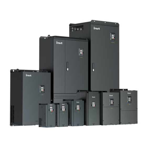
INVT Goodrive300-01A Series Operation Manual

INVT Goodrive300-01A Series Operation Manual

Hide thumbs Also See for Goodrive300-01A Series:
Table of Contents

Advertisement

Quick Links

Advertisement

Table of Contents
loading
Need help?

Need help?

Do you have a question about the Goodrive300-01A Series and is the answer not in the manual?

Questions and answers

Summary of Contents for INVT Goodrive300-01A Series

  • Page 2 Goodrive300-01A series VFD for air compressor Change history Change description Version Release date First release V1.0 November 2020 … … …...
  • Page 3 Preface Goodrive300-01A series variable-frequency drive (VFD) for air compressors (hereinafter referred to as GD300-01A VFD) is designed and developed by INVT based on the requirements of the air compressor industry, which can be applied in the control of synchronous/asynchronous air compressor.
  • Page 4: Table Of Contents

    Goodrive300-01A series VFD for air compressor Contents Contents Preface ..............................i Contents ............................. ii 1 Safety precautions ......................... 1 1.1 What this chapter contains ..................... 1 1.2 Safety definition ........................1 1.3 Warning ..........................1 1.4 Safety guidelines ........................1 1.4.1 Delivery and installation ....................
  • Page 5 Goodrive300-01A series VFD for air compressor Contents P08 group Enhanced functions ................... 61 P09 group PID control ......................66 P11 group Protection parameters ..................69 P13 group Synchronous motor control parameters ............. 71 P14 group Serial communication ..................73 P17 group Status viewing ....................74 P18 group Functions for air compressors ................
  • Page 6 Goodrive300-01A series VFD for air compressor Contents B.3.2 Connection terminals ....................163 B.3.3 Wiring description ....................164 B.3.4 Cable description ..................... 164 B.3.5 Installation dimensions and description ..............165 B.4 Filter ........................... 166 B.5 Reactor ..........................167 Appendix C Current transformer of the fan ................168 C.1 Current transformer model selection ..................
  • Page 7: Safety Precautions

    Goodrive300-01A series VFD for air compressor Safety precautions 1 Safety precautions 1.1 What this chapter contains Read this manual carefully and follow all safety precautions before moving, installing, operating and servicing the product. Otherwise, equipment damage or physical injury or death may be caused.
  • Page 8: Delivery And Installation

    Goodrive300-01A series VFD for air compressor Safety precautions  Do not perform wiring, inspection or component replacement when power supply is applied. Ensure that all the input power supplies are disconnected before wiring and inspection, and always wait for at least the time designated on the VFD or until the DC bus voltage is less than 36V.
  • Page 9: Commissioning And Running

    Goodrive300-01A series VFD for air compressor Safety precautions  Prevent the screws, cables and other conductive objects from falling into the VFD.  The leakage current of the VFD may be above 3.5mA during operation. Ground with proper techniques and ensure the grounding resistor is less than 10Ω. The conductivity of PE grounding conductor is the same as that of the phase conductor (with the same cross sectional area).
  • Page 10: Scrap Treatment

    Goodrive300-01A series VFD for air compressor Safety precautions maintenance and component replacement.  Do not carry out any insulation voltage-endurance test on the VFD or measure the control circuit of the VFD by megameter.  Take anti-static measures on the VFD and internal parts during maintenance and component replacement.
  • Page 11: Product Overview

    Goodrive300-01A series VFD for air compressor Product overview 2 Product overview 2.1 Product specification Category Function Specification 3PH 220V (-15%)–240V (+10%); Rated voltage: 220V Input voltage of 3PH 380V (-15%)–440V (+10%); Rated voltage: 380V the VFD (V) 3PH 520V (-15%)–690V (+10%); Rated voltage: 660V...
  • Page 12 Goodrive300-01A series VFD for air compressor Product overview Category Function Specification 1 input (standard): PTA1/PTB1 1 input (optional): PTA2/PTB2 Analog Resolution: 1℃ temperature input Range: -20℃~150℃ Accuracy error: 3℃ 1 output (standard): AO1/GND Analog output 0–10V/0–20mA 3 inputs (standard): S1, S2, S3...
  • Page 13: Product Nameplate

    Goodrive300-01A series VFD for air compressor Product overview 2.2 Product nameplate IP20 Model: GD300-01A-022G-4-E Power(Output): 22kW Input: AC 3PH 380V(-15%)-440V(+10%) 44A 47Hz-63Hz Output: AC 3PH 0V-Uinput 45A 0Hz-400Hz S/N: Made in China Shenzhen INVT Electric Co.,Ltd. Figure 2-1 Product nameplate Note: This is a nameplate example of a standard model.
  • Page 14: Rated Specifications

    Goodrive300-01A series VFD for air compressor Product overview 2.4 Rated specifications Rated values of AC 3PH 220V(-15%)–240V(+10%) VFDs Output Output Input Structural installation Product model power current current (A) dimensions (kW) Same with GD300-01A-7R5G-2-E GD300-01A-015G-4-E Same with GD300-01A-011G-2-E GD300-01A-022G-4-E Same with...
  • Page 15 Goodrive300-01A series VFD for air compressor Product overview Rated values of AC 3PH 380V(-15%)–240V(+10%) VFDs Output power Input current Output current Model (kW) GD300-01A-7R5G-4-E 18.5 GD300-01A-011G-4-E GD300-01A-015G-4-E GD300-01A-018G-4-E 18.5 GD300-01A-022G-4-E GD300-01A-030G-4-E GD300-01A-037G-4-E GD300-01A-045G-4-E GD300-01A-055G-4-E GD300-01A-075G-4-E GD300-01A-090G-4-E GD300-01A-110G-4-E GD300-01A-132G-4-E GD300-01A-160G-4-E GD300-01A-185G-4-E...
  • Page 16 Goodrive300-01A series VFD for air compressor Product overview Rated values of AC 3PH 520V(-15%)–690V(+10%) VFDs Output power Input current Output current Model (kW) GD300-01A-022G-6-E GD300-01A-030G-6-E GD300-01A-037G-6-E GD300-01A-045G-6-E GD300-01A-055G-6-E GD300-01A-075G-6-E GD300-01A-090G-6-E GD300-01A-110G-6-E GD300-01A-132G-6-E GD300-01A-160G-6-E GD300-01A-185G-6-E GD300-01A-200G-6-E GD300-01A-220G-6-E GD300-01A-250G-6-E GD300-01A-280G-6-E GD300-01A-315G-6-E GD300-01A-350G-6-E...
  • Page 17: Wiring Instruction

    Goodrive300-01A series VFD for air compressor Wiring instruction 3 Wiring instruction 3.1 Main circuit wiring and terminal description 3.1.1 Main circuit wiring diagram For VFDs of AC 3PH 380V (-15%)–440V (+10%) Figure 3-1 Main circuit wiring diagram for 7.5kW VFD models Note: DC reactors are optional parts for 7.5kW VFD models and can be built into the models.
  • Page 18 Goodrive300-01A series VFD for air compressor Wiring instruction Figure 3-3 Main circuit wiring diagram for 18.5–110kW VFD models Note: DC reactors have been built into 18.5–110kW VFD models as standard configuration. Figure 3-4 Main circuit wiring diagram for 132–500kW VFD models Note: DC reactors are optional parts for 132–500kW VFD models and can be externally connected.
  • Page 19: Main Circuit Terminal Diagram

    Goodrive300-01A series VFD for air compressor Wiring instruction copper bar between P1 and (+). DC reactors are optional parts. 3.1.2 Main circuit terminal diagram Figure 3-6 Main circuit terminal diagram for 380V 7.5kW VFD models Figure 3-7 Main circuit terminal diagram for 380V 11–15kW VFD models Figure 3-8 Main circuit terminal diagram for 380V 18.5–22kW VFD models...
  • Page 20 Goodrive300-01A series VFD for air compressor Wiring instruction Figure 3-9 Main circuit terminal diagram for 380V 30–37kW VFD models Figure 3-10 Main circuit terminal diagram for 380V 45–55kW VFD models Figure 3-11 Main circuit terminal diagram for 380V 75kW VFD models...
  • Page 21 Goodrive300-01A series VFD for air compressor Wiring instruction Figure 3-12 Main circuit terminal diagram for 380V 90–110kW VFD models Figure 3-13 Main circuit terminal diagram for 380V 132–200kW VFD models -15-...
  • Page 22 Goodrive300-01A series VFD for air compressor Wiring instruction A1 A2 POWER MOTOR Figure 3-14 Main circuit terminal diagram for 380V 220–350kW VFD models Figure 3-15 Main circuit terminal diagram for 380V 400–500kW VFD models Table 3-1 Screw specification and torque of main circuit terminals...
  • Page 23 Goodrive300-01A series VFD for air compressor Wiring instruction Terminal screw Torque of torque driver Power range (kW) · specification 220–350 400–500 Table 3-2 Main circuit terminal description Terminal name Terminal Terminal function 7.5kW and 18.5– sign 11–15kW 132kW and higher...
  • Page 24 Goodrive300-01A series VFD for air compressor Wiring instruction Figure 3-16 Main circuit terminal diagram for 660V 22–45kW VFD models Figure 3-17 Main circuit terminal diagram for 660V 55–132kW VFD models Figure 3-18 Main circuit terminal diagram for 660V 160–220kW VFD models...
  • Page 25 Goodrive300-01A series VFD for air compressor Wiring instruction A1 A2 POWER MOTOR Figure 3-19 Main circuit terminal diagram for 660V 250–350kW VFD models Figure 3-20 Main circuit terminal diagram for 660V 400–630kW VFD models Table 3-3 Screw specification and torque of main circuit terminals...
  • Page 26 Goodrive300-01A series VFD for air compressor Wiring instruction Terminal screw Torque of torque driver Power range (kW) · specification 400–630 Table 3-4 Main circuit terminal description Terminal name Terminal Terminal function sign 22–132kW 160kW and higher input terminals, R, S, T...
  • Page 27: Control Circuit Wiring And Terminal Description

    Goodrive300-01A series VFD for air compressor Wiring instruction 3.2 Control circuit wiring and terminal description GD300-01A series Emergency stop to touch screen or controller User-defined Shielded cable Motor Twisted pair overtemperature protection Pressure transmitter Relay 1 output Analog output Relay 2 output...
  • Page 28 Goodrive300-01A series VFD for air compressor Wiring instruction Category Sign Name Terminal function screen. You can select 24V output or 24V and 1.1Ω resistor series connection output through the jumper J11. By default, 24V output is selected in factory. 24V reference...
  • Page 29 Goodrive300-01A series VFD for air compressor Wiring instruction Category Sign Name Terminal function You can slect the matching terminal resistor through the jumper J4. By default, the matching resistor is not connected. Communication You can choose to connect the communication cable...
  • Page 30 Goodrive300-01A series VFD for air compressor Wiring instruction Category Sign Name Terminal function PE to 0V short connect the jumper J7 between 0V and PE depending on the situation. CGND is short connected by default. When PE/CGND interferences occur to communication, you can short...
  • Page 31: Commissioning Instruction

    Main motor Figure 4-1 Wiring diagram for dual-VFD air compressor system 4.1.2 Commissioning steps for the dual-VFD air compressor It is recommended to use touch screen special for INVT air compressor to display and commission. Note:  If you use a controller from another manufacturer, contact INVT technical support.
  • Page 32 Goodrive300-01A series VFD for air compressor Commissioning instruction Figure 4-2 Login interface 3. Click Enter IN to enter the working environment interface, as shown in Figure 4-3. Figure 4-3 Working interface -26-...
  • Page 33 Goodrive300-01A series VFD for air compressor Commissioning instruction 4. Click Menu on the top right corner of the user interface, and the interface is displayed, as shown in Figure 4-4. Figure 4-4 Menu interface 5. Click System config on the touch screen to enter the system configuration interface, as shown in Figure 4-5.
  • Page 34 Goodrive300-01A series VFD for air compressor Commissioning instruction rated power, rated voltage, rated current, pole pairs, and carrier frequency.  If you select AM (asynchronous motor), you need to set the max frequency, rated frequency, rated power, rated voltage, rated current, rated rotational speed, and carrier frequency.
  • Page 35 Goodrive300-01A series VFD for air compressor Commissioning instruction Figure 4-7 Fan motor parameter setting interface Step 2 On the system configuration interface, click Set up Parameters. The system completes the related parameter configuration automatically. Step 3 Click Next to enter Parameters Configuration or click Back to return to system configuration.
  • Page 36 Goodrive300-01A series VFD for air compressor Commissioning instruction Step 4 On the system configuration interface, click Debug Mode, and the interface is displayed, as shown in Figure 4-9. Figure 4-9 Debug mode interface Click Jog for the main motor to determine the motor rotation direction; click Load or Unload to test the action of solenoid valve.
  • Page 37 Goodrive300-01A series VFD for air compressor Commissioning instruction 7. Choose Maintenance parameter in the menu, and the interface is displayed, as shown in Figure 4-11. Figure 4-11 Maintenance parameter interface 8. Choose Protect parameter in the menu, and the interface is displayed, as shown in Figure 4-12.
  • Page 38 Goodrive300-01A series VFD for air compressor Commissioning instruction Figure 4-13 Running information interface 10. After adjusting user parameters, factory parameters and maintenance parameters according to the manual, return to Workspace interface and click Start to run. -32-...
  • Page 39: Commissioning Guidance For Single-Vfd Air Compressor

    Goodrive300-01A series VFD for air compressor Commissioning instruction 4.2 Commissioning guidance for single-VFD air compressor 4.2.1 Wiring diagram for single-VFD air compressor system Power-frequency transformer Solenoid coil 220V 110V RO1A Contactor coil RO1C RO2C RO2A Emergency stop Multi-function expansion card...
  • Page 40 Goodrive300-01A series VFD for air compressor Commissioning instruction 2. Choose Fan Parameters. Set the fan rated current according to the fan nameplate. Figure 4-16 Fan parameter interface 3. After adjusting user parameters, factory parameters and maintenance parameters according to the touch screen manual, return to the Working environment interface, and click Start to run.
  • Page 41: Function Description

    Goodrive300-01A series VFD for air compressor Function description 5 Function description 5.1 Function parameter list "○" indicates that the value of the parameter can be modified when the VFD is in stopped or running state. "◎" indicates that the value of the parameter cannot be modified when the VFD is in running state.
  • Page 42 Goodrive300-01A series VFD for air compressor Function description Function Name Description Default Modify code 0: Keypad 1: Analog P1- Setting channel 2: Reserved ○ P00.06 of A frequency 3: Analog P2- command 4: Reserved 5: Reserved 6: Multi-step speed running...
  • Page 43: P01 Group Start And Stop Control

    Goodrive300-01A series VFD for air compressor Function description Function Name Description Default Modify code 0: No operation 1: Rotary autotuning Motor 2: Static autotuning 1 (comprehensive ◎ P00.15 parameter autotuning) autotuning 3: Static autotuning 2 (partial autotuning, only support asynchronous motor)
  • Page 44 Goodrive300-01A series VFD for air compressor Function description Function Name Description Default Modify code Starting frequency ○ P01.09 of DC braking for 0.00–P00.03 (max. output frequency) 0.00Hz stop Wait time before DC ○ P01.10 0.00–50.00s 0.00s braking for stop DC braking current ○...
  • Page 45: P02 Group Motor 1 Parameters

    Goodrive300-01A series VFD for air compressor Function description Function Name Description Default Modify code Wait time for restart ○ P01.22 0.0–3600.0s (valid when P01.21=1) 1.0s after power-off ○ P01.23 Start delay 0.0–60.0s 0.0s ○ P01.24 Stop speed delay 0.0–100.0 s 0.0s...
  • Page 46 Goodrive300-01A series VFD for air compressor Function description Function Name Description Default Modify code No-load current Model ○ P02.10 0.1–6553.5A of AM 1 depended Magnetic saturation ◎ P02.11 coefficient 1 of 0.0–100.0% 80.0% iron core of AM Magnetic saturation ◎...
  • Page 47 Goodrive300-01A series VFD for air compressor Function description Function Name Description Default Modify code Direct-axis Model ○ P02.21 inductance of 0.01–655.35mH depended SM 1 Quadrature-axis Model ○ P02.22 inductance of 0.01–655.35mH depended SM 1 Counter-emf ○ P02.23 constant of SM 0–10000...
  • Page 48: P03 Group Vector Control

    Goodrive300-01A series VFD for air compressor Function description Function Name Description Default Modify code Power calibration ○ P02.28 0.00–3.00 1.00 coefficient of motor 1 Parameter display 0: Displayed according to the motor type ○ P02.29 selection of 1: All displayed...
  • Page 49 Goodrive300-01A series VFD for air compressor Function description Function Name Description Default Modify code Power generation slip ○ P03.08 compensation 50%–200.0% 100% coefficient of vector control 0–65535 Model ○ P03.09 proportional The default value of P03.09 P03.10 depended coefficient P...
  • Page 50 Goodrive300-01A series VFD for air compressor Function description Function Name Description Default Modify code rotation frequency) upper-limit 2: Reserved frequency in 3: P2- (100% corresponding to the max. torque control frequency) 4–5: Reserved 6: Modbus communication (same as the above) 7–9: Reserved...
  • Page 51 Goodrive300-01A series VFD for air compressor Function description Function Name Description Default Modify code 4: Reserved 5: Modbus communication (same as the above) 6–8: Reserved 0: Keypad (P03.21) 1: P1- (100% corresponding to three times the motor rated current) Setting source...
  • Page 52: P04 Group Svpwm Control

    Goodrive300-01A series VFD for air compressor Function description Function Name Description Default Modify code Speed display 0: Display the actual value ○ P03.27 selection in 1: Display the set value vector control IF starting ○ P03.28 0–100.0% (of the motor rated current) 60.0%...
  • Page 53: P05 Group Input Terminals

    Goodrive300-01A series VFD for air compressor Function description Function Name Description Default Modify code V/F slip ○ P04.09 compensation 0.0–200.0% 100.0% gain of motor 1 Low-frequency oscillation ○ P04.10 0–100 control factor of motor 1 High-frequency oscillation ○ P04.11 0–100...
  • Page 54 Goodrive300-01A series VFD for air compressor Function description Function Name Description Default Modify code function 4: Jog forward 5: Jog reversely selection 6: Coast to stop ◎ P05.04 Function of S4 7: Reset faults ◎ P05.05 Function of S5 8: Pause running ◎...
  • Page 55 Goodrive300-01A series VFD for air compressor Function description Function Name Description Default Modify code Setting range: 0x00 –0xFF Digital input ○ P05.11 0.000–1.000s 0.100s filter time 0: Virtual terminals are invalid Virtual 1: Modbus communication virtual terminals ◎ P05.12 terminal...
  • Page 56 Goodrive300-01A series VFD for air compressor Function description Function Name Description Default Modify code S7 switch-on ○ P05.26 0.000–50.000s 0.000s delay S7 switch-off ○ P05.27 0.000–50.000s 0.000s delay S8 switch-on ○ P05.28 0.000–50.000s 0.000s delay S8 switch-off ○ P05.29 0.000–50.000s 0.000s...
  • Page 57: P06 Group Output Terminals

    Goodrive300-01A series VFD for air compressor Function description Function Name Description Default Modify code P2 input filter ○ P05.46 0.000s–10.000s 0.200s time ○ P05.47 PT2 lower limit 0.00V–P05.49 0.00V Corresponding ○ P05.48 setting of PT2 -100.0%–100.0% 6.3% lower limit PT2 upper ○...
  • Page 58 Goodrive300-01A series VFD for air compressor Function description Function Name Description Default Modify code 3: Running reversely 4: Jogging ○ P06.01 RO5 output 5: VFD in fault 6: FDT1 7: Reserved ○ P06.02 RO3 output 8: Frequency reached 9: Running in zero speed...
  • Page 59 Goodrive300-01A series VFD for air compressor Function description Function Name Description Default Modify code BIT7 BIT6 BIT5 BIT4 BIT3 BIT2 BIT1 BIT0 Setting range: 0–0x3F ○ P06.06 switch-on 0.000–50.000s 0.000s delay ○ P06.07 switch-off 0.000–50.000s 0.000s delay ○ P06.08 switch-on 0.000–50.000s...
  • Page 60 Goodrive300-01A series VFD for air compressor Function description Function Name Description Default Modify code rated current of the motor) 6: Output voltage (relative to 1.5 times the rated voltage of the VFD) 7: Output power (relative to two times the...
  • Page 61: P07 Group Hmi

    Goodrive300-01A series VFD for air compressor Function description Function Name Description Default Modify code ○ P06.23 switch-off 0.000–50.000s 0.000s delay ○ P06.27 switch-on 0.000–50.000s 0.000s delay ○ P06.28 switch-off 0.000–50.000s 0.000s delay 0: Voltage 1: Current Note: When switching the AO1 analog output...
  • Page 62 Goodrive300-01A series VFD for air compressor Function description Function Name Description Default Modify code 0: No function 1: Jogging 2: Switch display status through the shifting 3: Forward/reverse running switching Function of ◎ P07.02 4: Clear the setting of UP/DOWN...
  • Page 63 Goodrive300-01A series VFD for air compressor Function description Function Name Description Default Modify code 0x0000–0xFFFF BIT0: Analog P1- value (V on) BIT1–BIT3: Reserved Selection 2 of BIT4: Motor overload percentage (% on) parameters BIT5: VFD overload percentage (% on) ○...
  • Page 64 Goodrive300-01A series VFD for air compressor Function description Function Name Description Default Modify code Software version ● P07.13 1.00–655.35 of control board Accumulated ● P07.14 0–65535h running time High bit of power ● P07.15 consumption of 0–65535 kWh(*1000) the VFD Low bit of power ●...
  • Page 65 Goodrive300-01A series VFD for air compressor Function description Function Name Description Default Modify code 4: Overcurrent at acceleration (OC1) ● P07.29 2nd-last fault type 5: Overcurrent at deceleration (OC2) 6: Overcurrent at constant speed (OC3) 7: Overvoltage at acceleration (OV1) ●...
  • Page 66 Goodrive300-01A series VFD for air compressor Function description Function Name Description Default Modify code Running ● P07.33 frequency at 0.00 present fault Ramp reference ● P07.34 frequency at 0.00 present fault Output voltage at ● P07.35 present fault Output current at ●...
  • Page 67: P08 Group Enhanced Functions

    Goodrive300-01A series VFD for air compressor Function description Function Name Description Default Modify code Output terminal ● P07.48 status at last fault Running ● P07.49 frequency at last fault Ramp reference ● P07.50 frequency at 0.00 2nd-last fault Output voltage at ●...
  • Page 68 Goodrive300-01A series VFD for air compressor Function description Function Name Description Default Modify code Low-voltage ○ P08.16 protection 0.0V–2000.0V 300.0V threshold Overvoltage ○ P08.17 pre-protection 0.0V–2000.0V 780.0V threshold Automatic ○ P08.18 0.0–6000.0s 60.0s restart delay Low-voltage ○ P08.19 frequency limit 0.0–6000.0s...
  • Page 69 Goodrive300-01A series VFD for air compressor Function description Function Name Description Default Modify code (Direct-axis inductance of SM 1) and P02.22 (Quadrature-axis inductance of SM 1) are used in the calculation. 1: Disable Applicable embedded/surface-mounted synchronous motors. The actual value of P02.21 (Direct-axis inductance of SM 1) is...
  • Page 70 Goodrive300-01A series VFD for air compressor Function description Function Name Description Default Modify code modulation 1: PWM mode 2, 3PH modulation LED tens: PWM low-speed carrier limit 0: Low-speed carrier limit mode 1 1: Low-speed carrier limit mode 2 2: No limit LED hundreds: Reserved 0x00–0x11...
  • Page 71 Goodrive300-01A series VFD for air compressor Function description Function Name Description Default Modify code Integral time of ○ P08.43 digital 0.01–10.00s 0.10s potentiometer 0x00–0x221 LED ones: Frequency enabling selection 0: UP/DOWN terminal setup is valid 1: UP/DOWN terminal setup is invalid LED tens: Frequency control selection 0: Valid only when P00.06=0...
  • Page 72: P09 Group Pid Control

    Goodrive300-01A series VFD for air compressor Function description Function Name Description Default Modify code 0: Save the setting at power-off. 1: Clear the setting at power-off. High bit of initial ○ P08.48 value of power 0–59999° ( k) 0kWh consumption Low bit of initial ○...
  • Page 73 Goodrive300-01A series VFD for air compressor Function description Function Name Description Default Modify code 0: PID output characteristic is positive: the feedback signal is larger than PID reference, which requires the VFD output frequency to decrease to balance PID, e.g. tension PID PID output control of winding.
  • Page 74 Goodrive300-01A series VFD for air compressor Function description Function Name Description Default Modify code changes by 100% during the time set by P09.06, the regulation quantity of differential regulator (ignoring proportional and integral actions) the max. output frequency (P00.03). The longer the differential time, the stronger the regulation intensity.
  • Page 75: P11 Group Protection Parameters

    Goodrive300-01A series VFD for air compressor Function description Function Name Description Default Modify code 1: Stop integral regulation when the frequency reaches upper/lower limit LED hundreds: 0: The same with the set direction 1: Contrary to the set direction Differential ○...
  • Page 76 Goodrive300-01A series VFD for air compressor Function description Function Name Description Default Modify code Overvoltage stall ○ 120–150% (standard bus voltage) (380V) P11.04 140% protection voltage 0x00–0x11 Ones: Current-limit action selection 0: Current-limit action is invalid 1: Current-limit action is always valid...
  • Page 77: P13 Group Synchronous Motor Control Parameters

    Goodrive300-01A series VFD for air compressor Function description Function Name Description Default Modify code Overload ○ P11.10 pre-alarm 0.1–3600.00s 1.0s detection time Underload ○ P11.11 pre-alarm 0%–P11.09 detection level Underload ○ P11.12 pre-alarm 0.1–3600.0s 1.0s detection time 0x00–0x11 LED ones:...
  • Page 78 Goodrive300-01A series VFD for air compressor Function description Function Name Description Default Modify code Switching ○ P13.04 frequency of 0.00Hz–P00.03 (max. output frequency) 30.00Hz pull-in current High-frequency superposing ◎ P13.05 200Hz–1000Hz 500Hz frequency (reserved) High--frequency 0.0–300.0% (of the rated voltage of the ◎...
  • Page 79: P14 Group Serial Communication

    Goodrive300-01A series VFD for air compressor Function description P14 group Serial communication Function Name Description Default Modify code Local ○ P14.00 communication 1–247; 0 indicates a broadcast address address 0: 1200BPS 1: 2400BPS Communication 2: 4800BPS ○ P14.01 baud rate...
  • Page 80: P17 Group Status Viewing

    Goodrive300-01A series VFD for air compressor Function description P17 group Status viewing Function Name Description Default Modify code ● P17.00 Set frequency 0.00Hz–P00.03 0.00Hz Output ● P17.01 0.00Hz–P00.03 0.00Hz frequency Ramp ● P17.02 reference 0.00Hz–P00.03 0.00Hz frequency ● P17.03 Output voltage 0–1200V ●...
  • Page 81 Goodrive300-01A series VFD for air compressor Function description Function Name Description Default Modify code Display analog input voltage value of PT1 channel. Under air-compressor mode, connect PT100 thermal resistor temperature sensor, different temperature generates different resistor value, PT1 input different...
  • Page 82 Goodrive300-01A series VFD for air compressor Function description Function Name Description Default Modify code Setting range: -100.0–100.0% Motor power ● P17.25 -1.00–1.00 factor Current ● P17.26 0–65535m running time ASR controller ● P17.28 -300.0%–300.0% (of the motor rated current) 0.0%...
  • Page 83: P18 Group Functions For Air Compressors

    Goodrive300-01A series VFD for air compressor Function description Function Name Description Default Modify code while the keypad TRIP indicator flashes. The warning code only acts as a warning prompt, and does not lead to failure shutdown. Status of 0: No card ●...
  • Page 84 Goodrive300-01A series VFD for air compressor Function description Function Name Description Default Modify code compressor loads/unloads automatically after starting. 0: Machine head temperature PT 1, auxiliary temperature PT2 Temperature 1: Machine head temperature PT 2, auxiliary ◎ P18.03 sensor channel...
  • Page 85 Goodrive300-01A series VFD for air compressor Function description Function Name Description Default Modify code compressor runs stably, the fan speed is controlled by thermostatic PID (P18.42=0), Setting PID calculation is carried out via P18.10 ○ P18.10 75℃ temperature the machine head temperature to realize thermostatic control.
  • Page 86 Goodrive300-01A series VFD for air compressor Function description Function Name Description Default Modify code Setting range: 0–3600s Pre-alarm When current discharge pressure is higher ○ P18.17 0.90Mpa pressure than P18.17, the system indicates pressure pre-alarm by setting BIT8 of P19.13 to 1.
  • Page 87 Goodrive300-01A series VFD for air compressor Function description Function Name Description Default Modify code It determines the converging speed of temperature PID regulator, the larger the value of K, the stronger the converging Convergence ○ P18.25 intensity, however, if is too large, 0.12...
  • Page 88 Goodrive300-01A series VFD for air compressor Function description Function Name Description Default Modify code It is used to calibrate temperature detection circuit before shipment. PT2 calibration ○ P18.32 3.41V Connect to the resistor whose resistance is voltage 1 (20℃) the same with that of PT100 at 20° C, read the voltage value of P17.22...
  • Page 89 Goodrive300-01A series VFD for air compressor Function description Function Name Description Default Modify code 2: Both of pressure P1 and P2 are displayed (valid only when P18.00=0) 0.00–20.00 Mpa It is related to the actual range of pressure Upper limit of sensor, the corresponding voltage of P18.04...
  • Page 90: P19 Group Air Compressor Status Viewing

    Goodrive300-01A series VFD for air compressor Function description Function Name Description Default Modify code to ensure the running current of the master is below the automatic frequency reduction threshold. 0–8000h When it is set to “0”, maintenance timeout function will be invalid. When it is set to a...
  • Page 91 Goodrive300-01A series VFD for air compressor Function description Function Name Description Default Modify code The set time ● P19.04 maintenance on part 5 Running time ● P19.05 of part 1 Running time ● P19.06 of part 2 Running time ●...
  • Page 92 Goodrive300-01A series VFD for air compressor Function description Function Name Description Default Modify code Present temperature P18.03=0 P19.12 P18.28 P18.29 P17.20 PT1 input voltage Present temperature P18.03=1 P19.12 P18.33 P18.32 P17.22 PT2 input voltage Range: -20–150℃ 0000–0xFFFF BIT0: Air filter blockage signal 1: Fault;...
  • Page 93 Goodrive300-01A series VFD for air compressor Function description Function Name Description Default Modify code BIT12: Pressure signal 1: Pressure signal fault; 0: Normal BIT13: Temperature signal 1: Temperature signal fault; 0: Normal BIT14: Low-temperature protection 1: Low-temperature alarm; 0: Normal BIT15: Master state 1: Run;...
  • Page 94 Goodrive300-01A series VFD for air compressor Function description Function Name Description Default Modify code BIT15: Emergency stop signal 1: Emergency stop signal alarm, 0: Normal 0: Standby 1: Run 2: Fault 3: Emergency stop ● P19.15 Device state 4: Undervoltage...
  • Page 95 Goodrive300-01A series VFD for air compressor Function description Function Name Description Default Modify code Present auxiliary pressure Mpa P18.37=0 P18.38 P19.20 P05.42 P17.21 P05.44 P2 input voltage Present auxiliary pressure Mpa P18.37=1 P18.04 P19.20 P05.32 P17.19 P05.34 P1 input voltage Range: 0.00–655.35Mpa...
  • Page 96: P20 Group Function For Water Lubrication

    Goodrive300-01A series VFD for air compressor Function description Function Name Description Default Modify code 1: Negative sequence 2: Phase loss Input power ● P19.23 0–2000V voltage P20 group Function for water lubrication Function Name Description Default Modify code 0–4 Water...
  • Page 97: P21 Group Power-Frequency Fan Protection

    Goodrive300-01A series VFD for air compressor Function description Function Name Description Default Modify code BIT8: Changing and discharging water to medium water level BIT9: Changing and replenishing water to medium water level BIT10: Changing and replenishing water to high water level...
  • Page 98 Goodrive300-01A series VFD for air compressor Function description Function Name Description Default Modify code 1.00–3.00 Current Among the current of three phases of the fan, ○ P21.03 imbalance if the ratio between max. current and min. 1.60 coefficient current is larger than P21.03, the VFD displays fan current imbalance fault.
  • Page 99: P25 Group Fault Policy

    Goodrive300-01A series VFD for air compressor Function description Function Name Description Default Modify code Display current of B ● P21.14 0.0–40.0A 0.0A phase of the Display current of C ● P21.15 0.0–40.0A 0.0A phase of the Sampling value of A ●...
  • Page 100 Goodrive300-01A series VFD for air compressor Function description Function Name Description Default Modify code 0–0x6666 Ones: Overcurrent at deceleration (OC2) User-defined Tens: Overcurrent at constant speed (OC3) ○ P25.01 fault action 0x0000 Hundreds: Overvoltage at acceleration (OV1) selection 2 Thousands:...
  • Page 101 Goodrive300-01A series VFD for air compressor Function description Function Name Description Default Modify code 0–0x6666 User-defined Ones: To-ground short circuit fault 2 (ETH2) ○ P25.08 fault action Tens: Speed deviation fault (dEu) 0x5200 selection 9 Hundreds: Mal-adjustment fault (STo) Thousands: Underload fault (LL) 0–0x6666...
  • Page 102: Control Logic Of The Air Compressor

    Goodrive300-01A series VFD for air compressor Function description 5.2 Control logic of the air compressor (1) The following figure shows the control logic of the air compressor. Standby Start command Restart delay P18.16 reached No-load running Stop delay Stop command P18.14 reached...
  • Page 103 Goodrive300-01A series VFD for air compressor Function description (2) The following figure shows the pressure and running frequency control during the running of the air compressor. Current pressure p P18.05 P18.07 P18.06 时间 Current running frequency P00.04 P18.11 P18.12 P01.15 时间...
  • Page 104: Fault Policy Function Description

    Goodrive300-01A series VFD for air compressor Function description speed is controlled by pressure PID. P18.07 is used to set the air supply pressure when the air compressor runs stably. The VFD keeps the discharge pressure constant by regulating the master speed.
  • Page 105 Goodrive300-01A series VFD for air compressor Function description Fault policy Meaning function selection for more than 10 minutes, the VFD will automatically clear the cumulative number of automatic resets times (P17.18).  If you press the RST key during auto fault reset, auto fault reset is stopped forcibly, and the number of automatic fault reset times (P17.18) is cleared.
  • Page 106 Goodrive300-01A series VFD for air compressor Function description Factory default fault policy functions Item Fault Overcurrent at deceleration ✔ (OC2) Overcurrent at constant ✔ speed (OC3) Overvoltage at acceleration ✔ (OV1) Overvoltage at deceleration ✔ (OV2) Overvoltage at constant ✔...
  • Page 107 Goodrive300-01A series VFD for air compressor Function description Factory default fault policy functions Item Fault ✔ Input overvoltage (IOV) ✔ Input undervoltage (IUV) To-ground short-circuit fault ✔ 1 (ETH1) To-ground short-circuit fault ✔ 2 (ETH2) ✔ Speed deviation fault (dEu) ✔...
  • Page 108: Fault Information And Fault Handling

    Goodrive300-01A series VFD for air compressor Fault information and fault handling 6 Fault information and fault handling 6.1 VFD faults and solutions Fault contents and solutions for GD300-01A VFD are shown below. Fault Fault type Possible cause Solution code • Acceleration is too fast.
  • Page 109 Goodrive300-01A series VFD for air compressor Fault information and fault handling Fault Fault type Possible cause Solution code • Increase acceleration time. • Acceleration is too fast. • Restart the motor after stop. • The motor is restarted • Check grid voltage.
  • Page 110 Goodrive300-01A series VFD for air compressor Fault information and fault handling Fault Fault type Possible cause Solution code • Motor parameters are set nameplate parameters improperly. correctly. • The deviation between the • Empty the motor load and parameters obtained from identify again.
  • Page 111 Goodrive300-01A series VFD for air compressor Fault information and fault handling Fault Fault type Possible cause Solution code • Replace the hall. faulty. • Actual motor power setup • Replace main control To-ground ETH2 differs sharply from the board/drive board.
  • Page 112: Fault Contents And Solutions Of Air Compressor Equipment

    Goodrive300-01A series VFD for air compressor Fault information and fault handling Fault Fault type Possible cause Solution code the current transformation ratio (P21.01) is the same with current transformer nameplate. • Actually detected fan current is too large, it is recommended to increase the power.
  • Page 113 Goodrive300-01A series VFD for air compressor Fault information and fault handling P19.13 State type Possible cause Solution • Check whether fan control parameters are set correctly. Actual temperature detected • Whether the fan operates Temperature by PT1 is higher than the BIT9=1 normally.
  • Page 114 Goodrive300-01A series VFD for air compressor Fault information and fault handling P19.13 State type Possible cause Solution protection threshold set by circuit is abnormal. • Actual temperature is too P18.21. low, and low -temperature pre-alarm reported accordingly, and therefore the air compressor cannot start.
  • Page 115 Goodrive300-01A series VFD for air compressor Fault information and fault handling P19.14 State type Possible cause Solution • Pressure detection sensor The actual voltage detected is abnormal. • The pressure is set to a too Auxiliary pressure by P2 is larger than the...
  • Page 116 Goodrive300-01A series VFD for air compressor Fault information and fault handling P19.14 State type Possible cause Solution enter overtime maintenance stage, and hereafter, if the running time exceeds the time set by P18.45 again, maintenance timeout alarm will be reported.
  • Page 117: Appendix A Product Dimensions

    Goodrive300-01A series VFD for air compressor Product dimensions Appendix A Product dimensions A.1 Keypad diagram Function indicator Digital Unit indicator display area Increase/ decrease Confirmation Program/exit Short-cut multi- Right shift key function key Stop/fault Run key reset key A.2 External keypad installation dimensions 88.0...
  • Page 118: Wall Installation Dimensions Of 380V-440V Vfds

    Goodrive300-01A series VFD for air compressor Product dimensions A.3 Wall installation dimensions of 380V–440V VFDs For VFDs of AC 3PH 380V (-15%)–440V (+10%) Figure A-1 Wall installation diagram for 380V 7.5kW–37kW VFD models Figure A-2 Wall installation diagram for 380V 45kW–55kW VFD models...
  • Page 119 Goodrive300-01A series VFD for air compressor Product dimensions Figure A-3 Wall installation diagram for 380V 75kW VFD models Figure A-4 Wall installation diagram for 380V 90kW–110kW VFD models Figure A-5 Wall installation diagram for 380V 132kW–200kW VFD models -113-...
  • Page 120 Goodrive300-01A series VFD for air compressor Product dimensions Figure A-6 Wall installation diagram for 380V 220kW–350kW VFD models Table A-1 Wall installation dimension of 7.5kW–315kW single VFDs (unit: mm) Diameter Screw Power mounting specification hole — 7.5kW 303.5 196.5 —...
  • Page 121: Flange Installation Dimensions Of 380V-440V Vfds

    Goodrive300-01A series VFD for air compressor Product dimensions 400kW–500kW 1700 1678 560 240 22\12 A.4 Flange installation dimensions of 380V–440V VFDs For VFDs of AC 3PH 380V (-15%)–440V (+10%) Ø5.0 H1H2 4-R2 Figure A-9 Flange installation diagram for 380V 7.5kW–55kW VFD models Figure A-10 Flange installation diagram for 380V 7.5kW VFD models...
  • Page 122 Goodrive300-01A series VFD for air compressor Product dimensions 4-R2 Figure A-12 Flange installation diagram for 380V 132kW–200kW VFD models Table A-3 Flange installation dimension of 380V 7.5kW–200kW VFD models (unit: mm) Diameter Screw Power W1 W2 W3 W4 H1 H2...
  • Page 123: Wall Installation Dimensions Of 520V-690V Vfds

    Goodrive300-01A series VFD for air compressor Product dimensions A.5 Wall installation dimensions of 520V–690V VFDs For VFDs of AC 3PH 520V (-15%)–690V (+10%) Figure A-13 Wall installation diagram for 660V 22kW–132kW VFD models Figure A-14 Wall installation diagram for 660V 160kW–220kW VFD models Figure A-15 Wall installation diagram for 660V 250kW–350kW VFD models...
  • Page 124: Flange Installation Dimensions Of 520V-690V Vfds

    Goodrive300-01A series VFD for air compressor Product dimensions Table A-4 Wall installation dimension of 660V 22kW–350kW single VFDs (unit: mm) Diameter Screw Power mounting specification hole — 22 kW -45kW — — 55kW–132kW — — 160kW–220kW — — 250kW–350kW A.6 Flange installation dimensions of 520V–690V VFDs For VFDs of AC 3PH 520V (-15%)–690V (+10%)
  • Page 125: Floor Installation Dimensions Of 520V-690V Vfds

    Goodrive300-01A series VFD for air compressor Product dimensions Figure A-17 Flange installation diagram for 660V 160kW–220kW VFD models Table A-5 Flange installation dimension of 660V 22kW–220kW VFD models (unit: mm) Diameter Screw Power W1 W2 H2 H3 H4 D1 mounting...
  • Page 126: Product Weight And Package Dimensions Of 380V-440V Vfds

    Goodrive300-01A series VFD for air compressor Product dimensions Figure A-19 Floor installation diagram for 660V 400kW–630kW VFD models Table A-6 Wall installation dimension of 660V 250kW–630kW single VFDs (unit: mm) Diameter of Screw Power mounting specification hole 250kW–350kW 750 1410 1390 13\12 400kW–630kW 620...
  • Page 127: Product Weight And Package Dimensions Of 520V-660V Vfds

    Goodrive300-01A series VFD for air compressor Product dimensions Package dimension Product model N/W (kg) G/W (kg) (mm) GD300-01A-132G-4-E 76.0 97.0 971x631x565 GD300-01A-160G-4-E 76.0 97.0 971x631x565 GD300-01A-185G-4-E 76.0 97.0 971x631x565 GD300-01A-200G-4-E 76.0 97.0 971x631x565 GD300-01A-220G-4-E 1086x826x595 GD300-01A-250G-4-E 1086x826x595 GD300-01A-280G-4-E 1086x826x595 GD300-01A-315G-4-E...
  • Page 128: Appendix B External Optional Accessories

    Goodrive300-01A series VFD for air compressor External optional accessories Appendix B External optional accessories B.1 Multi-function expansion card EC-IO304 B.1.1 Brief introduction Table B-1 Ordering description Name Model Order No. Remarks Multi-function Includes three M4*L8.5 hexagonal studs and 11023– expansion...
  • Page 129 Goodrive300-01A series VFD for air compressor External optional accessories Control board interface Serial port downlo ading Simul ation interfa +24V RO3A RO4A RO5A RO6A PTA2 PTB2 Figure B-4 Terminal layout diagram of the multi-function expansion card Table B-2 User terminal description of the multi-function expansion card...
  • Page 130: Assembly Instruction

    Goodrive300-01A series VFD for air compressor External optional accessories Category Terminal Name Description relay 4 NO contact of RO5A relay 5 NO contact of RO6A relay 6 Common contact of relay 3–6 P1- analog signal I corresponds to current signal, V corresponds to selection terminal voltage signal, and the default is current input signal.
  • Page 131 Goodrive300-01A series VFD for air compressor External optional accessories Keypad Upper cover screw Upper cover Lower cover screw Lower cover 2. Remove one fastening screw (and grounding wires) on the control board. Control board screws Grounding wires 3. Install three hexagonal studs to support the multi-functional expansion card. The installation torque is 12±...
  • Page 132 Goodrive300-01A series VFD for air compressor External optional accessories M4XL8.5 hexagonal studs 4. Install the multi-functional expansion card (and grounding wires), and use three M4*8 combination screws with spring and flat washers. The installation torque is 10± 10%kgf.cm. Multifunction expansion card...
  • Page 133: Rs485 Communication Lcd Keypad

    Goodrive300-01A series VFD for air compressor External optional accessories Multifunction expansion card Control board B.2 RS485 communication LCD keypad B.2.1 LCD keypad introduction GD300-01A series VFD supports the use of the optional LCD keypad that uses RS485 communication. The LCD keypad can be used to control the start and stop of the VFD, read and write the status data, and set the parameters.
  • Page 134 Goodrive300-01A series VFD for air compressor External optional accessories clock can work properly even after power failure. Table B-3 Ordering description for the RS485 communication LCD keypad Item Description Order No. Remarks Includes a 2.5-meter RS485 keypad RS485 cable, a 2.5-meter emergency stop...
  • Page 135 Goodrive300-01A series VFD for air compressor External optional accessories Name Description indicator ③, logic: steady off) 5: Coast to stop (linked with indicator ③, logic: steady off) 6: Switch running-command giving modes in order (linked with indicator ③, logic: steady off)
  • Page 136: Lcd Keypad Structure

    Goodrive300-01A series VFD for air compressor External optional accessories Name Description To replace or mount the clock battery, remove Battery Clock battery ⑭ this cover, and then close the cover after the cover cover battery is mounted. The mini USB terminal is used to connect to the ⑮...
  • Page 137: Setting Parameters On The Lcd Keypad

    Goodrive300-01A series VFD for air compressor External optional accessories B.2.3.2 Cable description Emergency stop signal Emergency stop signal Figure B-8 Emergency stop cable diagram Note: The emergency stop cable is used for emergency stop control when a device fault occurs and it is often connected to the S1 terminal and COM terminal.
  • Page 138 Goodrive300-01A series VFD for air compressor External optional accessories 03.17 16:02:35 PMSM air compressor system Software ver:V1.00 ConfigTB ver:V1.00 Enter Figure B-10 Initial interface B.2.4.2 Working environment interface The working environment interface displays certain parameters about the running. Device Status 03.17 16:02:35...
  • Page 139 Goodrive300-01A series VFD for air compressor External optional accessories Parameter Description Undervoltage: indicates that the master VFD bus voltage is too low. In this case, you need to check the input power supply. Alarm: The alarm type is displayed in the pre-alarm area.
  • Page 140 Goodrive300-01A series VFD for air compressor External optional accessories B.2.4.3 Setting interface In the main interface, you can press Set to enter the following interface: 03.17 16:02:35 Reset Load Unload Start Stop Return Home Confirm Figure B-12 Setting interface In this interface, you can press the Up or Down key to select different operation functions. Then press OK for control;...
  • Page 141 Goodrive300-01A series VFD for air compressor External optional accessories 03.17 16:02:35 Real-time alarm 000. 03-17 16:00:05 xxx fault 001. 03-17 15:49:30 xxx fault 002. 03-17 15:08:20 xxx fault Return Home Figure B-13 Real-time alarm interface B.2.4.5 Main menu interface In the main interface, you can press...
  • Page 142 Goodrive300-01A series VFD for air compressor External optional accessories B.2.4.6 User parameter interface 1. Enter the user parameter interface through the main menu. 03.17 16:02:35 User param Set pressure xxx.xx Mpa Unloading pressure xxx.xx Mpa Loading pressure xxx.xx Mpa Setting Temp...
  • Page 143 Goodrive300-01A series VFD for air compressor External optional accessories User parameter Initial value Function temperature fan is started. After the startup, the air compressor runs with load with this Loading delay specified delay. If the manual mode is used, both load and unload need to be manually performed after the air compressor is started.
  • Page 144 Goodrive300-01A series VFD for air compressor External optional accessories User parameter Initial value Function Startup action: Disable/enable (Timed startup is valid only in Enabled state. Otherwise, the device is not automatically started even though the scheduled startup time has been set.)
  • Page 145 Goodrive300-01A series VFD for air compressor External optional accessories 03.17 16:02:35 Loading Pressure Set value xx.x Max. 020.00 MPa Min. 000.00 MPa Return Home Confirm Figure B-18 Loading pressure setting interface 03.17 16:02:35 Sleep Function Disable Enable Return Home Confirm Figure B-19 Sleep function selection interface 03.17 16:02:35...
  • Page 146 Goodrive300-01A series VFD for air compressor External optional accessories 03.17 16:02:35 Timing switch setting Mon. Tues. Wed. Thurs. Fri. Sat. Return Home Select Figure B-21 Date selection interface 03.17 16:02:35 Mon. Boot time ShutTime Boot Shutdown 0 0:0 0 0 0:0 0...
  • Page 147 Goodrive300-01A series VFD for air compressor External optional accessories 03.17 16:02:35 Maintain param Air filter set time xxxxxx h Oil filter set time xxxxxx h Splitter set time xxxxxx h Lubricat Oil set time xxxxxx h Grease set time xxxxxx h...
  • Page 148 Goodrive300-01A series VFD for air compressor External optional accessories Maintenance Initial Function parameter value Oil filter run time It is cleared when a new oil filter is used. Splitter run time It is cleared when a new splitter is used.
  • Page 149 Goodrive300-01A series VFD for air compressor External optional accessories 03.17 16:02:35 Oil filter run time Current value xxxxx Return Home Clear Figure B-27 Accumulative oil filter use time B.2.4.8 Protection parameter interface 1. Enter the protection parameter interface through the main menu.
  • Page 150 Goodrive300-01A series VFD for air compressor External optional accessories Protection Initial Function parameter value When the actual air supply pressure is higher than this pressure, Prealarm pressure 0.90Mpa a pre-alarm is reported. When the actual air supply pressure is higher than this pressure, Alarm pressure 1.00Mpa...
  • Page 151 Goodrive300-01A series VFD for air compressor External optional accessories 03.17 16:02:35 Please enter current password: Return Home Confirm Figure B-29 Administrator password input interface 03.17 16:02:35 Alarm Pressure Set value xx.x Max. 020.00 MPa Min. 000.00 MPa Return Home Confirm Figure B-30 Alarm pressure parameter setting interface 03.17 16:02:35...
  • Page 152 Goodrive300-01A series VFD for air compressor External optional accessories 03.17 16:02:35 Run information Master Return Home Select Figure B-32 Running information interface 03.17 16:02:35 Master running info Output Current xxxx.x A Output Voltage xxxxxx V Motor Speed xxxxxx rpm Output Freq xxx.xx Hz...
  • Page 153 Goodrive300-01A series VFD for air compressor External optional accessories 03.17 16:02:35 Master Param Max Ouput Freq xxx.xx Hz Run Freq Up limit xxx.xx Hz Run Freq Down limit xxx.xx Hz Load Run Low Limit Freq xxx.xx Hz No-load Run Freq xxx.xx Hz...
  • Page 154 Goodrive300-01A series VFD for air compressor External optional accessories Master parameter Initial value Function Upper limit of It indicates the upper limit of the output frequency of 50.00Hz running frequency the VFD. Lower limit of It indicates the lower limit of the output frequency of 00.00Hz...
  • Page 155 Goodrive300-01A series VFD for air compressor External optional accessories 03.17 16:02:35 Differential time Set value xx.x Max. 010.00 s Min. 000.00 s Return Home Confirm Figure B-38 Figure B-38 Differential time setting interface B.2.4.11 Fan parameter interface 1. Enter the fan parameter interface through the main menu.
  • Page 156 Goodrive300-01A series VFD for air compressor External optional accessories Fan parameter Initial value Function Phase B current Setting range: 0.0–150.0% calibration coefficient Note: When parameters are restored to the factory settings, this value is remained. Phase C current calibration coefficient 2.
  • Page 157: Fault Records

    Goodrive300-01A series VFD for air compressor External optional accessories B.2.5 Fault records The fault record interface is used to display the fault and alarm information about current device running. If an alarm is reported, alarm information is displayed. Fault records include VFD faults, air compressor faults, real-time alarms, and historic alarms.
  • Page 158 Goodrive300-01A series VFD for air compressor External optional accessories B.2.5.2 Air compressor fault interface This interface displays air compressor exception information, including the air filter, oil filter, and separator blockage, maintenance need, and auxiliary pressure or temperature pre-alarm or alarm.
  • Page 159: Vfd Information

    Goodrive300-01A series VFD for air compressor External optional accessories 03.17 16:02:35 Please enter current password: Return Home Confirm 03.17 16:02:35 Confirm to clear the realtime alarm info? Return Home Confirm Figure B-47 Alarm record clearing interface Note: The real-time alarm interface can keep a maximum of 50 fault records due to the restriction of memory.
  • Page 160: System Configuration

    Goodrive300-01A series VFD for air compressor External optional accessories 03.17 16:02:35 VFD information Master Return Home Select Figure B-48 VFD information interface 03.17 16:02:35 Master VFD info Ctrl Board Software Ver xxx.xx Present Temperature xxxx.x Digital Input Terminal State xxxxxx...
  • Page 161 Goodrive300-01A series VFD for air compressor External optional accessories 03.17 16:02:35 Systerm config Factory debug guide Password setting Time setting Backlight setting Function code search VFD model Return Home Select Param copy function Return Home Select Figure B-50 System configuration interface B.2.7.1 Factory commissioning wizard...
  • Page 162 Goodrive300-01A series VFD for air compressor External optional accessories 03.17 16:02:35 Master param setting Motor type Max frequency 050.00 Mpa Rated power 0090.0 kW Rated frequency 050.00 Hz Rated voltage 000380 V Rated current 0176.0 A Return Home Edit 03.17 16:02:35 Master param setting 00.030 Ω...
  • Page 163 Goodrive300-01A series VFD for air compressor External optional accessories Step 3 Press the Set up Parameters key to automatically set parameters. Step 4 Enter the commissioning mode. Run the master and fan in jogging mode to check the motor rotation direction.
  • Page 164 Goodrive300-01A series VFD for air compressor External optional accessories 03.17 16:02:35 03.17 16:02:35 Modify password Modify password Please enter current password: Please enter new password: Note:The setting rage of password is 0-9999 Return Home Confirm Return Home Confirm 03.17 16:02:35 03.17 16:02:35...
  • Page 165 Goodrive300-01A series VFD for air compressor External optional accessories 03.17 16:02:35 Backlight setting 03.17 16:02:35 Brightness setting Brightness setting Set value: Time setting Note: When it is set to 0,the brightness setting function is invalid Return Home Select Return Home...
  • Page 166 Goodrive300-01A series VFD for air compressor External optional accessories Figure B-59 lists the supported VFD series. In future, more VFD series may be supported. 03.17 16:02:35 VFD model GD300-01A GD300-21(Master) GD300-21(Fan) GD300-01A-RT GD300-01A-E Return Home Select Figure B-59 VFD model selection interface B.2.7.8 Parameter copying...
  • Page 167: Hmi Touch Screen

    Goodrive300-01A series VFD for air compressor External optional accessories 03.17 16:02:35 Function copy function Param upload Param download 1(All param) Param download 2(Non-Motor param) Param download 3(Only-Motor param) Return Home Confirm Figure B-61 Parameter copying function 2 B.2.7.9 Language setting The 485 LCD keypad supports switching between Chinese and English.
  • Page 168 Goodrive300-01A series VFD for air compressor External optional accessories Category Function Specifications Ethernet None USB port 1 USB Slave 2.0 port; 1 USB Host 2.0 port Program download USB Slave/U disk method COM1:RS232/RS485/RS422 Serial COM2: RS485 communication port COM3: RS232...
  • Page 169: Connection Terminals

    Goodrive300-01A series VFD for air compressor External optional accessories Table B-7 Ordering description for the touch screen Item Description Order No. Includes 3-meter RS485 HMI touch screen communication cable 11026–00011 3-meter 24V power supply cable. B.3.2 Connection terminals USB Host...
  • Page 170: Wiring Description

    Goodrive300-01A series VFD for air compressor External optional accessories Used to connect external peripherals such as USB Type A the USB disk and barcode scanning device USB Slave MicroUSB Used for program download and debugging B.3.3 Wiring description In order to drive and manage the air compressor better, use the provided RS485 communication cable, of which one end is connected to the touch screen power supply port and DB9 serial port and the other is connected to GD300-01A VFD control board terminal.
  • Page 171: Installation Dimensions And Description

    Goodrive300-01A series VFD for air compressor External optional accessories B.3.5 Installation dimensions and description B.3.5.1 Touch screen installation dimensions Figure B-64 Touch screen installation dimensions (unit: mm) B.3.5.2 Cut-out installation description When you want to build the touch screen into the operation panel of the control cabinet, use the cross screwdriver and metal installation snap-fit.
  • Page 172: Filter

    Goodrive300-01A series VFD for air compressor External optional accessories Back Front Bottom B.4 Filter Filter model selections for GD300-01A are shown below. Model Input filter Output filter GD300-01A-7R5G-4-E FLT-P04032L-B FLT-L04032L-B GD300-01A-011G-4-E GD300-01A-015G-4-E FLT-P04045L-B FLT-L04045L-B GD300-01A-018G-4-E GD300-01A-022G-4-E FLT-P04065L-B FLT-L04065L-B GD300-01A-030G-4-E GD300-01A-037G-4-E...
  • Page 173: Reactor

    Goodrive300-01A series VFD for air compressor External optional accessories B.5 Reactor When the distance between the VFD and motor is longer than 50 meters, the parasitic capacitance between the long cable and ground may cause large leakage current, and overcurrent protection of the VFD may be frequently triggered.
  • Page 174: Appendix C Current Transformer Of The Fan

    Goodrive300-01A series VFD for air compressor Current transformer of the fan Appendix C Current transformer of the fan C.1 Current transformer model selection Power of the cooling Rated current of cooling Recommended transformation ratio fan (kW) fan (A) of the transformer 0.75...
  • Page 175: Parameter Setup Of Current Transformer Of The Fan

    Goodrive300-01A series VFD for air compressor Current transformer of the fan to GD300-01A terminal expansion board S1 S2 S1 S2 R/A phase S/B phase Cables on fan side Cables on fan side R/A phase current S/B phase current Dotted terminal of...
  • Page 176: Appendix D Communication Protocol

    Goodrive300-01A series VFD for air compressor Communication protocol Appendix D Communication protocol D.1 Application mode The Modbus protocol of this VFD is RTU mode and the network line is RS485. The interface of RS485 works on semiduplex and its data signal adopts differential transmission mode which is also called balance transmission, too.
  • Page 177 Goodrive300-01A series VFD for air compressor Communication protocol Sub-function code Description 0000 Return to inquire information data Definition of data address The address definition of communication data is used to control VFD operations, obtain VFD state information and set function parameters.
  • Page 178 Goodrive300-01A series VFD for air compressor Communication protocol Function Address Data meaning description definition characteristics forward rotating (0–Fmax (unit: 0.01Hz)) The set value of upper limit frequency of 2006H reverse rotating (0–Fmax (unit: 0.01Hz)) Upper limit torque of electromotion torque 2007H (0–3000, 1000 corresponds to 100.0% of...
  • Page 179 Goodrive300-01A series VFD for air compressor Communication protocol Function Address Data meaning description definition characteristics BIT3: =1 running time of part 4 cleared to zero =0: invalid BIT4: =1 running time of part 5 cleared to zero =0: invalid BIT5: =1 device running time cleared to...
  • Page 180 Goodrive300-01A series VFD for air compressor Communication protocol Function Address Data meaning description definition characteristics Bit4: =0: Non-overload pre-alarm =1: Overload pre-alarm Bit5– Bit6: =00: Keypad control =01: Terminal control =10: communication control VFD fault code 2102H See fault type...
  • Page 181 Goodrive300-01A series VFD for air compressor Communication protocol Function Address Data meaning description definition characteristics Read current step number of 3012H multi-step speed External length 3013H value External 3014H counting value The set torque 3015H value identification 3016H code Fault code...
  • Page 182 Goodrive300-01A series VFD for air compressor Communication protocol Code Name Meaning error different from the lower computer. It only happen in write command, the reason maybe: Written 1. The written data exceeds the parameter range. 2. The parameter should not be modified now.
  • Page 183: Appendix E Common Emc Problems And Troubleshooting

    Goodrive300-01A series VFD for air compressor Common EMC problems and troubleshooting Appendix E Common EMC problems and troubleshooting E.1 Interference problems of meter switches and sensors Interference phenomena: The sensor signal (pressure, temperature, displacement, etc.) is collected and displayed via HMI...
  • Page 184: Unstoppable Or Shimmering Indicator Caused By Coupling Of Motor Cable

    Goodrive300-01A series VFD for air compressor Common EMC problems and troubleshooting If it is confirmed that the abnormality is caused by interference, rule out the problem cause by below means. Troubleshooting:  The communication cable cannot be routed with motor cable in the same cable tray.
  • Page 185: Leakage Current And Residual Current Device (Rcd)

    Goodrive300-01A series VFD for air compressor Common EMC problems and troubleshooting Solutions:  Check and confirm the abnormal signal cable is routed with motor cable motor cable at a distance of at least 20cm.  Connect in parallel the digital input terminal (S) used for start/stop control with other idle digital input terminals.
  • Page 186: Problem Of Charged Device Shell

    Goodrive300-01A series VFD for air compressor Common EMC problems and troubleshooting Check and confirm if secondary grounding occurred to the null line. Check and confirm if power cable terminal is in the air switch or the contactor is poorly contacted (loose screws).
  • Page 187 6 6 0 0 1 - 0 0 7 6 1...

Table of Contents