
Related Manuals for YASKAWA VIPA System SLIO


Summary of Contents for YASKAWA VIPA System SLIO
- Page 1 VIPA System SLIO CPU | 013-CCF0R00 | Manual HB300 | CPU | 013-CCF0R00 | en | 19-30 SPEED7 CPU 013C www.vipa.com/en/service-support/manuals...
- Page 2 VIPA GmbH Ohmstr. 4 91074 Herzogenaurach Telephone: 09132-744-0 Fax: 09132-744-1864 Email: info@vipa.com Internet: www.vipa.com 013-CCF0R0_000_CPU 013C,7,EN - © 2019...
-
Page 3: Table Of Contents
VIPA System SLIO Table of contents Table of contents General........................9 1.1 Copyright © VIPA GmbH ................. 9 1.2 About this manual................... 10 1.3 Safety information................... 11 Basics and mounting................... 12 2.1 Safety information for users................12 2.2 System conception..................13 2.2.1 Overview...................... - Page 4 VIPA System SLIO Table of contents 4.8 Setting standard CPU parameters..............78 4.8.1 Parameterization via Siemens CPU............78 4.8.2 Parameter CPU................... 78 4.8.3 Parameter for MPI/DP ................81 4.9 Setting VIPA specific CPU parameters............82 4.9.1 Free Module Mapping.................. 85 4.9.2 Access settings....................
- Page 5 VIPA System SLIO Table of contents 5.6.5 Counter operating modes................135 5.6.6 Counter - Additional functions..............142 5.6.7 Diagnostics and interrupt................148 5.7 Frequency measurement................148 5.7.1 Properties....................148 5.7.2 Wiring......................149 5.7.3 Proceeding....................150 5.7.4 Parametrization..................150 5.7.5 Status indication..................152 5.8 Pulse width modulation - PWM..............
- Page 6 VIPA System SLIO Table of contents 7.6 Usage in Siemens TIA Portal............... 195 7.6.1 Installation OPC UA Configurator.............. 196 7.6.2 Steps of the OPC UA configuration............198 7.7 Usage OPC UA Configurator................ 199 7.7.1 OPC UA Configurator................199 7.7.2 Project tree ....................
- Page 7 VIPA System SLIO Table of contents 10.9 PROFINET diagnostics................249 10.9.1 Overview....................249 10.9.2 Diagnostics with the configuration and engineering tool......249 10.9.3 Diagnostics during runtime in the user program........250 10.9.4 Diagnostics via OB start information............251 10.9.5 Diagnostics status indication via SSLs............ 251 10.10 PROFINET system limits................
- Page 8 VIPA System SLIO Table of contents 13.6 TIA Portal - Deployment PG/OP communication - PROFINET....305 13.6.1 Deployment as PROFINET IO controller..........305 13.6.2 Deployment as PROFINET I-Device............310 13.7 TIA Portal - Option: Deployment PROFIBUS communication....316 13.7.1 Fast introduction..................316 13.7.2 Activating bus functionality by means of a VSC........
-
Page 9: General
VIPA System SLIO General Copyright © VIPA GmbH General 1.1 Copyright © VIPA GmbH All Rights Reserved This document contains proprietary information of VIPA and is not to be disclosed or used except in accordance with applicable agreements. This material is protected by the copyright laws. It may not be reproduced, distributed, or... -
Page 10: About This Manual
VIPA System SLIO General About this manual Information product sup- Contact your local VIPA Customer Service Organization representative if you wish to port report errors or questions regarding the contents of this document. If you are unable to locate a customer service centre, contact VIPA as follows: VIPA GmbH, Ohmstraße 4, 91074 Herzogenaurach, Germany... -
Page 11: Safety Information
VIPA System SLIO General Safety information CAUTION! Damages to property is likely if these warnings are not heeded. Supplementary information and useful tips. 1.3 Safety information Applications conforming The system is constructed and produced for: with specifications communication and process control... -
Page 12: Basics And Mounting
VIPA System SLIO Basics and mounting Safety information for users Basics and mounting 2.1 Safety information for users Handling of electrostatic VIPA modules make use of highly integrated components in MOS-Technology. These sensitive modules components are extremely sensitive to over-voltages that can occur during electrostatic discharges. -
Page 13: System Conception
VIPA System SLIO Basics and mounting System conception > Overview 2.2 System conception 2.2.1 Overview System SLIO is a modular automation system for assembly on a 35mm mounting rail. By means of the peripheral modules with 2, 4 or 8 channels this system may properly be adapted matching to your automation tasks. -
Page 14: Components
VIPA System SLIO Basics and mounting System conception > Components 2.2.2 Components CPU (head module) Bus coupler (head module) Line extension Periphery modules Accessories CAUTION! Only modules of VIPA may be combined. A mixed operation with third- party modules is not allowed! - Page 15 VIPA System SLIO Basics and mounting System conception > Components Line extension In the System SLIO there is the possibility to place up to 64 modules in on line. By means of the line extension you can divide this line into several lines. Here you have to place a line extension master at each end of a line and the subsequent line has to start with a line extension slave.
-
Page 16: Accessories
VIPA System SLIO Basics and mounting System conception > Accessories 2.2.3 Accessories Shield bus carrier The shield bus carrier (order no.: 000-0AB00) serves to carry the shield bus (10mm x 3mm) to connect cable shields. Shield bus carriers, shield bus and shield fixings are not in the scope of delivery. -
Page 17: Hardware Revision
VIPA System SLIO Basics and mounting Dimensions 2.2.4 Hardware revision Hardware revision on the The hardware revision version is printed on every System SLIO module. front Since a System SLIO module consists of a terminal and electronics module, you will find a hardware revision on each of them. - Page 18 VIPA System SLIO Basics and mounting Dimensions Dimensions CPU 01x Dimensions bus coupler and line extension slave Dimensions line extension master HB300 | CPU | 013-CCF0R00 | en | 19-30...
- Page 19 VIPA System SLIO Basics and mounting Dimensions Dimension periphery module Dimensions electronic module Dimensions in mm HB300 | CPU | 013-CCF0R00 | en | 19-30...
-
Page 20: Mounting
VIPA System SLIO Basics and mounting Mounting > Mounting CPU 01xC 2.4 Mounting Requirements for UL compliance use – Use for power supply exclusively SELV/PELV power supplies. – The System SLIO must be installed and operated in a housing according to IEC 61010-1 9.3.2 c). - Page 21 VIPA System SLIO Basics and mounting Mounting > Mounting CPU 01xC Turn the locking lever upwards, place the CPU at the mounting rail and turn the lever downward. ð If you want to use the CPU without periphery modules, the mounting is now complete.
-
Page 22: Wiring
VIPA System SLIO Basics and mounting Wiring > Wiring CPU 01xC After mounting the whole system, to protect the backplane bus connectors at the last module you have to mount the bus cover, now. If the last module is a clamp module, for adaptation the upper part of the bus cover is to be removed. - Page 23 VIPA System SLIO Basics and mounting Wiring > Wiring CPU 01xC Wiring procedure Labeling on the casing Pin no. at the connector Release button Connection hole for wire Insert wire The wiring happens without a tool. Determine according to the casing labelling the connection position and insert through the round connection hole of the according contact your prepared wire until it stops, so that it is fixed.
- Page 24 VIPA System SLIO Basics and mounting Wiring > Wiring CPU 01xC Standard wiring (1) DC 24V for electronic section supply of the CPU, the internal I/Os and SLIO bus (2) DC 24V for power section supply integrated I/Os (3) DC 24V for power section supply SLIO bus The electronic power section supply is internally protected against higher voltage by fuse.
-
Page 25: Wiring Periphery Modules
VIPA System SLIO Basics and mounting Wiring > Wiring periphery modules To attach the shield the mounting of shield bus carriers are necessary. The shield bus carrier (available as accessory) serves to carry the shield bus to connect cable shields. - Page 26 VIPA System SLIO Basics and mounting Wiring > Wiring periphery modules Wiring procedure Pin number at the connector Opening for screwdriver Connection hole for wire Insert a suited screwdriver at an angel into the square opening as shown. Press and hold the screwdriver in the opposite direction to open the contact spring.
-
Page 27: Wiring Power Modules
VIPA System SLIO Basics and mounting Wiring > Wiring power modules 2.5.3 Wiring power modules Terminal module terminals Power modules are either integrated to the head module or may be installed between the periphery modules. With power modules, terminals with spring clamp technology are used for wiring. - Page 28 VIPA System SLIO Basics and mounting Wiring > Wiring power modules Standard wiring (1) DC 24V for power section supply I/O area (max. 10A) (2) DC 24V for electronic power supply bus coupler and I/O area PM - Power module For wires with a core cross-section of 0.08mm...
- Page 29 VIPA System SLIO Basics and mounting Wiring > Wiring power modules Fusing The power section supply is to be externally protected with a fuse, which corresponds to the maximum current. This means max. 10A is to be protected with a 10A fuse...
- Page 30 VIPA System SLIO Basics and mounting Wiring > Wiring power modules Power module 007-1AB10 (1) DC 24V for power section supply I/O area (max. 10A) (2) DC 24V for electronic power supply bus coupler and I/O area (3) DC 24V for power section supply I/O area (max. 4A)
- Page 31 VIPA System SLIO Basics and mounting Wiring > Wiring power modules Attach the cables with the accordingly stripped cable screen and fix it by the shield clamp with the shield bus. HB300 | CPU | 013-CCF0R00 | en | 19-30...
-
Page 32: Demounting
VIPA System SLIO Basics and mounting Demounting > Demounting CPU 01xC 2.6 Demounting 2.6.1 Demounting CPU 01xC Proceeding Remove connector By means of a screwdriver there is the possibility to remove the connectors e.g. for module exchange with a fix wiring. For this each connector has a release lever centrally on its top side. -
Page 33: Demounting Periphery Modules
VIPA System SLIO Basics and mounting Demounting > Demounting periphery modules To mount the CPU put it to the periphery module and push it, guided by the stripes, to the mounting rail. Turn all the locking lever downward, again. Plug again the electronic module, which you have removed before. For installation plug the electronic module guided by the strips at the lower side until this engages to the terminal module. - Page 34 VIPA System SLIO Basics and mounting Demounting > Demounting periphery modules For demounting and exchange of a (head) module or a group of modules, due to mounting reasons you always have to remove the electronic module right beside. After mounting it may be plugged again.
- Page 35 VIPA System SLIO Basics and mounting Demounting > Demounting periphery modules Exchange of a module Power-off your system. group Remove if exists the wiring of the module group. For demounting and exchange of a (head) module or a group of modules, due to mounting reasons you always have to remove the electronic module right beside.
- Page 36 VIPA System SLIO Basics and mounting Demounting > Demounting periphery modules 2.6.2.1 Easy Maintenance Overview Easy Maintenance means the support for adding and removing modules during operation without having to restart the system. There are the following behaviors: Electronic module is removed –...
-
Page 37: Trouble Shooting - Leds
VIPA System SLIO Basics and mounting Trouble shooting - LEDs 2.7 Trouble shooting - LEDs General Each module has the LEDs RUN and MF on its front side. Errors or incorrect modules may be located by means of these LEDs. -
Page 38: Installation Guidelines
VIPA System SLIO Basics and mounting Installation guidelines 2.8 Installation guidelines General The installation guidelines contain information about the interference free deployment of a PLC system. There is the description of the ways, interference may occur in your PLC, how you can make sure the electromagnetic compatibility (EMC), and how you manage the isolation. - Page 39 VIPA System SLIO Basics and mounting Installation guidelines Proof the correct fixing of the lead isolation. – Data lines must be laid isolated. – Analog lines must be laid isolated. When transmitting signals with small ampli- tudes the one sided laying of the isolation may be favourable.
-
Page 40: General Data
VIPA System SLIO Basics and mounting General data 2.9 General data Conformity and approval Conformity 2014/35/EU Low-voltage directive 2014/30/EU EMC directive Approval Refer to Technical data others RoHS 2011/65/EU Restriction of the use of certain hazardous substances in electrical and electronic equipment... - Page 41 VIPA System SLIO Basics and mounting General data Mounting conditions Mounting place In the control cabinet Mounting position Horizontal and vertical Standard Comment Emitted interference EN 61000-6-4 Class A (Industrial area) Noise immunity EN 61000-6-2 Industrial area zone B EN 61000-4-2...
-
Page 42: Hardware Description
VIPA System SLIO Hardware description Properties Hardware description 3.1 Properties CPU 013-CCF0R00 SPEED7 technology integrated Programmable via VIPA SPEED7 Studio, Siemens SIMATIC Manager or TIA Portal Integrated work memory 64kbyte (32kbyte code, 32kbyte data) Work memory expandable up to 128kbyte (64kbyte code, 64kbyte data) -
Page 43: Structure
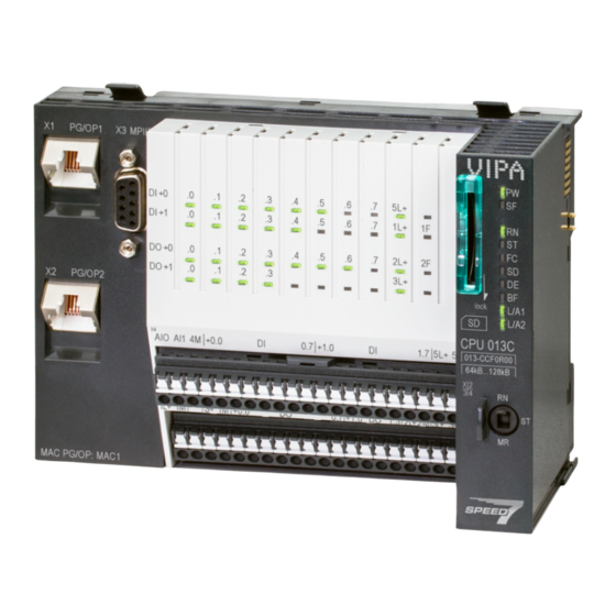
VIPA System SLIO Hardware description Structure > Interfaces 3.2 Structure 3.2.1 Compact CPU CPU 013C Locking lever X1: Ethernet PG/OP channel 1 X3: MPI(PtP) interface X2: Ethernet PG/OP channel 2 X4, X5: Connector IO part DI +x: LEDs integrated DI... - Page 44 VIPA System SLIO Hardware description Structure > Interfaces X1/X2: Ethernet PG/OP 8pin RJ45 jack: channel The RJ45 jack serves as interface to the Ethernet PG/OP channel. This interface allows you to program respectively remote control your CPU and to access the internal web server.
- Page 45 VIPA System SLIO Hardware description Structure > Interfaces X4: Connector Function Type Description AI 0 AI0: Analog input AI 0 AI 1 AI1: Analog input AI 1 Analog 0V 4M: GND for analog inputs DI 0 +0.0: Digital input DI 0 / Counter 0 (A) * DI 1 +0.1: Digital input DI 1 / Counter 0 (B) / Frequency 0 *...
- Page 46 VIPA System SLIO Hardware description Structure > Interfaces X5: Connector Function Type Description Sys DC 24V 1L+: DC 24V for electronic section supply Sys 0V 1M: GND for electronic section supply reserved DC 24V S+: DC 24V for sensor 1M: GND for sensor DO 0 +0.0: Digital output DO 0 / PWM 0 / Output channel counter 0...
-
Page 47: Memory Management
VIPA System SLIO Hardware description Structure > Buffering mechanisms X5: Electronic power supply The CPU has an integrated power supply. The power supply has to be provided with DC 24V. Via the power supply not only the internal electronic of the CPU is provided with voltage, but also the electronic from the integrated IO modules and the sensor output. -
Page 48: Operating Mode Switch
VIPA System SLIO Hardware description Structure > Operating mode switch CAUTION! Please connect the CPU for approximately 1 hour to the power supply, so that the internal buffering mechanism is loaded accordingly. In case of failure of the buffer mechanism Date and Time 01.09.2009 00:00:00 set. -
Page 49: Leds
VIPA System SLIO Hardware description Structure > LEDs 3.2.7 LEDs LEDs CPU part DI +x: LEDs integrated DI (DI +0.0 ... DI +1.7) DO +x: LEDs integrated DO (DO +0.0 ... DO +1.3) xL+: LEDs power supply xF: LEDs error... - Page 50 VIPA System SLIO Hardware description Structure > LEDs Power supply Description green DC 24V electronic section supply OK DC 24V electronic section supply not available DC 24V power section supply outputs OK DC 24V power section supply outputs not available...
- Page 51 VIPA System SLIO Hardware description Structure > LEDs LEDs CPU Description green yellow yellow yellow Boot-up after PowerON - as soon as the CPU is supplied with 5V, the green PW-LED (Power) is on. Firmware is loaded, here the SF-LED flickers.
- Page 52 VIPA System SLIO Hardware description Structure > LEDs LEDs Ethernet PG/OP channel L/A1 Description L/A2 green The corresponding Ethernet PG/OP channel is physically connected to the Ethernet. The corresponding Ethernet PG/OP channel is not physically connected to the Ethernet. The corresponding Ethernet PG/OP channel indicates Ethernet activity, here the LED flickers.
-
Page 53: Technical Data
VIPA System SLIO Hardware description Technical data 3.3 Technical data Order no. 013-CCF0R00 Type CPU 013C Module ID Technical data power supply Power supply (rated value) DC 24 V Power supply (permitted range) DC 20.4...28.8 V Reverse polarity protection ü... - Page 54 VIPA System SLIO Hardware description Technical data Order no. 013-CCF0R00 Input characteristic curve IEC 61131-2, type 1 Initial data size 16 Bit Technical data digital outputs Number of outputs Cable length, shielded 1000 m Cable length, unshielded 600 m Rated load voltage...
- Page 55 VIPA System SLIO Hardware description Technical data Order no. 013-CCF0R00 Number of inputs Cable length, shielded 200 m Rated load voltage Reverse polarity protection of rated load voltage Current consumption from load voltage L+ (without load) Voltage inputs ü Min. input resistance (voltage range) 100 kΩ...
- Page 56 VIPA System SLIO Hardware description Technical data Order no. 013-CCF0R00 Destruction limit resistance thermometer inputs Thermocouple inputs Thermocouple ranges Operational limit of thermocouple ranges Operational limit of thermocouple ranges with SFU Basic error limit thermoelement ranges Basic error limit thermoelement ranges with SFU...
- Page 57 VIPA System SLIO Hardware description Technical data Order no. 013-CCF0R00 Output current ranges Operational limit of current ranges Radical error limit current ranges with SFU Destruction limit against external applied voltage Settling time for ohmic load Settling time for capacitive load...
- Page 58 VIPA System SLIO Hardware description Technical data Order no. 013-CCF0R00 Number of DP master via CP Operable function modules Operable communication modules PtP Operable communication modules LAN Status information, alarms, diagnostics Status display Interrupts Process alarm Diagnostic interrupt Diagnostic functions...
- Page 59 VIPA System SLIO Hardware description Technical data Order no. 013-CCF0R00 Number of S7 times S7 times remanence adjustable 0 up to 256 S7 times remanence adjustable not retentive Data range and retentive characteristic Number of flags 8192 Byte Bit memories retentive characteristic adjustable...
- Page 60 VIPA System SLIO Hardware description Technical data Order no. 013-CCF0R00 Analog outputs 1015 Analog inputs, central Analog outputs, central Integrated analog inputs Integrated analog outputs Technical data encoder supply Number of outputs Output voltage (typ) L+ (-1.5 V) Output voltage (rated value)
- Page 61 VIPA System SLIO Hardware description Technical data Order no. 013-CCF0R00 DP master optional DP slave optional Point-to-point interface ü 5V DC Power supply max. 90mA, isolated 24V DC Power supply max. 100mA, non-isolated Type Type of interface Connector Electrically isolated MP²I (MPI/RS232)
- Page 62 VIPA System SLIO Hardware description Technical data Order no. 013-CCF0R00 Activation/deactivation of DP slaves ü Direct data exchange (slave-to-slave communication) DPV1 ü Transmission speed, min. 9.6 kbit/s Transmission speed, max. 12 Mbit/s Number of DP slaves, max. Address range inputs, max.
- Page 63 VIPA System SLIO Hardware description Technical data Order no. 013-CCF0R00 Type Type of interface Connector Electrically isolated PG/OP channel Number of connections, max. Productive connections Fieldbus Point-to-point communication PtP communication ü Interface isolated ü RS232 interface RS422 interface RS485 interface ü...
- Page 64 VIPA System SLIO Hardware description Technical data Order no. 013-CCF0R00 Address range inputs, max. 2 KB Address range outputs, max. 2 KB Transmitting clock 1 ms Update time 1 ms .. 512 ms Isochronous mode Parallel operation as controller and I-Device ü...
- Page 65 VIPA System SLIO Hardware description Technical data Order no. 013-CCF0R00 User data per UDP connection, max. 1472 Byte WebVisu via PG/OP WebVisu is supported ü Max. number of connections WebVisu WebVisu supports HTTP ü WebVisu supports HTTPS ü OPC UA server via PG/OP OPC UA server is supported ü...
-
Page 66: Deployment Cpu 013-Ccf0R00
VIPA System SLIO Deployment CPU 013-CCF0R00 Start-up behavior Deployment CPU 013-CCF0R00 4.1 Please note! The following descriptions always refer to the usage in the Siemens SIMATIC Manager. Information on usage in the VIPA SPEED7 Studio or Siemens TIA Portal can be found here: Ä... -
Page 67: Addressing
VIPA System SLIO Deployment CPU 013-CCF0R00 Addressing > Default address assignment of the I/O part 4.4 Addressing 4.4.1 Overview To provide specific addressing of the installed peripheral modules, certain addresses must be allocated in the CPU. This address mapping is in the CPU as hardware configu- ration. -
Page 68: Addressing Periphery Modules
VIPA System SLIO Deployment CPU 013-CCF0R00 Addressing > Addressing periphery modules 4.4.3 Addressing periphery modules The CPU 013-CCF0R00 provides an periphery area (address 0 ... 2047) and a process image of the in- and outputs (each address default 0 ... 127). The size of the process Ä... -
Page 69: Hardware Configuration - Cpu
VIPA System SLIO Deployment CPU 013-CCF0R00 Hardware configuration - CPU 4.5 Hardware configuration - CPU Precondition The configuration of the CPU takes place at the ‘hardware configurator’ of the Sie- mens SIMATIC Manager V 5.5 SP2 and up. The configuration of the System SLIO CPU happens by means of a virtual PROFINET IO device ‘VIPA SLIO System’... - Page 70 VIPA System SLIO Deployment CPU 013-CCF0R00 Hardware configuration - CPU Use [New] to create a new subnet and assign valid IP address data for your PROFINET system. With firmware version V2.4.0 and up, you can access the Ethernet PG/OP channel via this IP address data. The configuration via an additional CP is no longer required, but still possible.
-
Page 71: Hardware Configuration - System Slio Modules
VIPA System SLIO Deployment CPU 013-CCF0R00 Hardware configuration - System SLIO modules 4.6 Hardware configuration - System SLIO modules System SLIO backplane To connect System SLIO modules, the CPU has a backplane bus, which must addition- ally to be supplied. Here up to 64 System SLIO modules can be connected. -
Page 72: Hardware Configuration - Ethernet Pg/Op Channel
VIPA System SLIO Deployment CPU 013-CCF0R00 Hardware configuration - Ethernet PG/OP channel 4.7 Hardware configuration - Ethernet PG/OP channel Overview Please note! – At the first commissioning respectively after a reset to factory setting the Ethernet interface has no IP address. -
Page 73: Take Ip Address Parameters In Project
VIPA System SLIO Deployment CPU 013-CCF0R00 Hardware configuration - Ethernet PG/OP channel > Take IP address parameters in project "Initialization" via PLC The initialization via PLC functions takes place with the following proceeding: functions Determine the current Ethernet (MAC) address of your Ethernet PG/OP channel. - Page 74 VIPA System SLIO Deployment CPU 013-CCF0R00 Hardware configuration - Ethernet PG/OP channel > Take IP address parameters in project 4.7.1.1 Configuration via integrated CPU interface Proceeding From firmware version V2.4.0 this variant for configuration is recommended. The fol- lowing advantages result:...
- Page 75 VIPA System SLIO Deployment CPU 013-CCF0R00 Hardware configuration - Ethernet PG/OP channel > Take IP address parameters in project 4.7.1.1.1 Time-of-day synchronization NTP method In the NTP mode (Network Time Protocol) the module sends as client time-of-day queries at regular intervals to all configured NTP servers within the sub net. You can define up to 4 NTP server.
- Page 76 VIPA System SLIO Deployment CPU 013-CCF0R00 Hardware configuration - Ethernet PG/OP channel > Take IP address parameters in project The configuration happens according to the following procedure: Open the Siemens hardware configurator and, if not already done, configure the Siemens CPU 314C-2 PN/DP (314-6EH04-0AB0 V3.3).
- Page 77 VIPA System SLIO Deployment CPU 013-CCF0R00 Hardware configuration - Ethernet PG/OP channel > Take IP address parameters in project 4.7.1.2.1 Time-of-day synchronization NTP method In the NTP mode (Network Time Protocol) the module sends as client time-of-day queries at regular intervals to all configured NTP servers within the sub net. You can define up to 4 NTP server.
-
Page 78: Setting Standard Cpu Parameters
VIPA System SLIO Deployment CPU 013-CCF0R00 Setting standard CPU parameters > Parameter CPU 4.8 Setting standard CPU parameters 4.8.1 Parameterization via Siemens CPU Parameterization via Since the CPU from VIPA is to be configured as Siemens CPU 314C-2 PN/DP Siemens (314-6EH04-0AB0 V3.3) in the Siemens hardware configurator, the standard parameters... - Page 79 VIPA System SLIO Deployment CPU 013-CCF0R00 Setting standard CPU parameters > Parameter CPU Startup Startup when expected/actual configuration differs – If the checkbox for ‘Startup when expected/actual configuration differ’ is dese- lected and at least one module is not located at its configured slot or if another type of module is inserted there instead, then the CPU does not switch to RUN mode and remains in STOP mode.
- Page 80 VIPA System SLIO Deployment CPU 013-CCF0R00 Setting standard CPU parameters > Parameter CPU The selected memory byte cannot be used for temporary data storage. Retentive Memory Number of Memory bytes from MB0 – Enter the number of retentive memory bytes from memory byte 0 onwards.
-
Page 81: Parameter For Mpi/Dp
VIPA System SLIO Deployment CPU 013-CCF0R00 Setting standard CPU parameters > Parameter for MPI/DP Diagnostics/Clock Report cause of STOP – Activate this parameter, if the CPU should report the cause of STOP to PG respectively OP on transition to STOP. -
Page 82: Setting Vipa Specific Cpu Parameters
VIPA System SLIO Deployment CPU 013-CCF0R00 Setting VIPA specific CPU parameters Properties – With this button the properties of the interface may be pre-set. Comment – You can enter the purpose of the interface. Address Diagnostics – A diagnostics address for the interface is to be pre-set here. In the case of an error the CPU is informed via this address. - Page 83 VIPA System SLIO Deployment CPU 013-CCF0R00 Setting VIPA specific CPU parameters Miscellaneous – Direct DX transition – PN MultipleWrite Ä 85 – Free Module Mapping – Reduced PDU size Ä 90 Access settings – Activation of interfaces and ports –...
- Page 84 VIPA System SLIO Deployment CPU 013-CCF0R00 Setting VIPA specific CPU parameters Miscellaneous Direct DX transition - if this parameter is activated, the integrated PROFIBUS DP master, if activated by VSC, shows the following behavior: – As long as a DP slave is in Data Exchange, i.e. in the DP slave standard diag- nostic data byte 0, bit 1 and byte 1, bit 0 have the status 0, this DP slave is directly taken from the DP master in Data Exchange.
-
Page 85: Free Module Mapping
VIPA System SLIO Deployment CPU 013-CCF0R00 Setting VIPA specific CPU parameters > Free Module Mapping 4.9.1 Free Module Mapping 4.9.1.1 Overview Free module mapping - With FMM you can use your CPU in different hardware variants without adapting your user program. You only have to adapt the FMM configuration in the CPU when config- uring the hardware variants. - Page 86 VIPA System SLIO Deployment CPU 013-CCF0R00 Setting VIPA specific CPU parameters > Free Module Mapping 4.9.1.2 FMM configuration Configuration The mapping of the modules is defined as configuration by the 64byte record set 0x7F. The data record is retentively stored in the CPU.
- Page 87 VIPA System SLIO Deployment CPU 013-CCF0R00 Setting VIPA specific CPU parameters > Free Module Mapping 4.9.1.3 Examples (1): Target configuration Slot target Slot - The mapping always refers to the slot of the target configuration. target Based on the target configuration, the following examples show how to determine the mapping values for the hardware variants.
- Page 88 VIPA System SLIO Deployment CPU 013-CCF0R00 Setting VIPA specific CPU parameters > Free Module Mapping Variant 2: Reversed slots and modules are missing (1): Target configuration Slot Slot Record set 0x7F target actual (2): Actual configuration Byte Mapping 0x01 0xFF...
- Page 89 VIPA System SLIO Deployment CPU 013-CCF0R00 Setting VIPA specific CPU parameters > Free Module Mapping Variant 3: Modules are ignored (1): Target configuration Slot Slot Record set 0x7F target actual (2): Actual configuration Byte Mapping empty 0x00 empty 0x00 0x03...
-
Page 90: Access Settings
VIPA System SLIO Deployment CPU 013-CCF0R00 Project transfer 4.9.2 Access settings Overview The ‘Access setting’ allows you to disable access to ports or protocols. The CPU has an integrated Device web page that shows information about the access ways via ‘Access Ä... -
Page 91: Transfer Via Mpi / Optional Profibus
VIPA System SLIO Deployment CPU 013-CCF0R00 Project transfer > Transfer via MPI / optional PROFIBUS To switch the interface X3 MPI(PtP) to PROFIBUS functionality you have to activate the according bus functionality by means of a VSC storage media from VIPA. By plugging the VSC storage card and then an overall reset the according functionality is activated. -
Page 92: Transfer Via Ethernet
VIPA System SLIO Deployment CPU 013-CCF0R00 Project transfer > Transfer via Ethernet Set in the register MPI the transfer parameters of your MPI net and type a valid address. Switch to the register Local connection. Set the COM port of the PCs and the transfer rate 38400baud for the MPI program- ming cable from VIPA. -
Page 93: Transfer Via Memory Card
VIPA System SLIO Deployment CPU 013-CCF0R00 Accessing the web server Click to ‘PLC è Download’ Download ® the dialog "Select target module" is opened. Select your target module and enter the IP address parameters of the Ethernet PG/OP channel for connection. Provided that no new hardware configura- tion is transferred to the CPU, the entered Ethernet connection is permanently stored in the project as transfer channel. -
Page 94: Device Web
VIPA System SLIO Deployment CPU 013-CCF0R00 Accessing the web server > Device web page CPU 4.11.1 Device web page CPU Overview Dynamic web page, which exclusively outputs information. On the device web page you will find information about your CPU, the connected modules and your WebVisu project. - Page 95 VIPA System SLIO Deployment CPU 013-CCF0R00 Accessing the web server > Device web page CPU Runtime Information Operation Mode Mode Mode Switch RUNP System Time 14.03.19 08:34:14:486 Date, time Time to change the operating mode Up Time 0 days 02 hrs 07 min 08 sec...
- Page 96 VIPA System SLIO Deployment CPU 013-CCF0R00 Accessing the web server > Device web page CPU VSC Information Memory Extension 64 kByte Profibus PB Master Active Feature Set Information Status Media present Information about enabled functions VSC Product Number 955-C000M20 VSC Product S/N...
- Page 97 VIPA System SLIO Deployment CPU 013-CCF0R00 Accessing the web server > Device web page CPU ARM Processor Load Measurement Cycle Time 100 ms Information for the support Last Value Average Of Last 10 Values Minimum Load Maximum Load Tab: ‘IP’...
- Page 98 VIPA System SLIO Deployment CPU 013-CCF0R00 Accessing the web server > Device web page CPU Start Conditions Here the start conditions for the OPC UA server are listed: Conflicting projects – Simultaneous use of an OPC UA and WebVisu project via the same interface is not permitted and results in the message ‘conflicting project on card’...
- Page 99 VIPA System SLIO Deployment CPU 013-CCF0R00 Accessing the web server > Device web page CPU For your CPU can process a WebVisu project, you have to activate the Ä Chap. 8.2 ‘Activate WebVisu functionality’ WebVisu functionality. page 212 General Information Feature –...
- Page 100 VIPA System SLIO Deployment CPU 013-CCF0R00 Accessing the web server > Device web page CPU Status of the WebVisu On the device web page at the tab ‘WebVisu’ via ‘Status’ you get the status of your WebVisu project. Status Meaning...
- Page 101 VIPA System SLIO Deployment CPU 013-CCF0R00 Accessing the web server > Device web page CPU PG/OP1: X1 When enabled the frames of PG/OP2: X2 are mirrored to PG/OP1: X1. PG/OP2: X2 When enabled the frames of PG/OP1: X1 are mirrored to PG/OP2: X2.
-
Page 102: Operating Modes
VIPA System SLIO Deployment CPU 013-CCF0R00 Operating modes > Overview 4.12 Operating modes 4.12.1 Overview The CPU can be in one of 4 operating modes: Operating mode STOP Operating mode START-UP (OB 100 - restart / OB 102 - cold start *) - Page 103 VIPA System SLIO Deployment CPU 013-CCF0R00 Operating modes > Overview Operating mode HOLD The CPU offers up to 3 breakpoints to be defined for program diagnosis. Setting and deletion of breakpoints happens in your programming environment. As soon as a break- point is reached, you may process your program step by step.
-
Page 104: Function Security
VIPA System SLIO Deployment CPU 013-CCF0R00 Operating modes > Function security 4.12.2 Function security The CPUs include security mechanisms like a Watchdog (100ms) and a parameterizable cycle time surveillance (parameterizable min. 1ms) that stop res. execute a RESET at the CPU in case of an error and set it into a defined STOP state. -
Page 105: Overall Reset
VIPA System SLIO Deployment CPU 013-CCF0R00 Overall reset 4.13 Overall reset Overview During the overall reset the entire user memory is erased. Data located in the memory card is not affected. You have 2 options to initiate an overall reset: Overall reset by means of the operating mode switch Overall reset by means of a configuration tool like e.g. -
Page 106: Firmware Update
VIPA System SLIO Deployment CPU 013-CCF0R00 Firmware update 4.14 Firmware update Overview You can find current firmware versions at www.vipa.com in the service area. There are the following possibilities for the firmware update: Ä Chap. 4.14.1 ‘Firmware update online’ Firmware update online - from FW V3.0.0 page 107 –... -
Page 107: Firmware Update Online
VIPA System SLIO Deployment CPU 013-CCF0R00 Firmware update > Firmware update online Current firmware at The latest firmware versions can be found in the service area at www.vipa.com. For www.vipa.com example the following file is necessary for the firmware update of the CPU 013-CCF0R00 and its components with hardware release 01: CPU 013C, Hardware release 01: Pb000265.pkb... -
Page 108: Firmware Update Via Memory Card
VIPA System SLIO Deployment CPU 013-CCF0R00 Firmware update > Firmware update via memory card Perform firmware update Switch the operating mode switch of your CPU in position STOP. Execute an overall reset. Ä Chap. 4.13 ‘Overall reset’ page 105 Open the CPU web page and select the ‘Firmware’ tab. - Page 109 VIPA System SLIO Deployment CPU 013-CCF0R00 Firmware update > Firmware update via memory card Transfer firmware from memory card into CPU Switch the operating mode switch of your CPU in position STOP. Turn off the power supply. Plug the memory card with the firmware file into the CPU. Please take care of the correct plug-in direction of the memory card.
-
Page 110: Reset To Factory Settings
VIPA System SLIO Deployment CPU 013-CCF0R00 Reset to factory settings 4.15 Reset to factory settings Proceeding With the following proceeding the internal RAM of the CPU is completely deleted and the CPU is reset to delivery state. Please regard that the MPI address is also reset to default 2 and the IP address of the Ethernet PG/OP channel is reset to 0.0.0.0! -
Page 111: Deployment Storage Media - Vsd, Vsc
VIPA System SLIO Deployment CPU 013-CCF0R00 Deployment storage media - VSD, VSC 4.16 Deployment storage media - VSD, VSC Overview At the front of the CPU there is a slot for storage media. Here the following storage media can be plugged: VSD - VIPA SD-Card –... - Page 112 VIPA System SLIO Deployment CPU 013-CCF0R00 Deployment storage media - VSD, VSC CAUTION! Please regard that the VSC must remain plugged when you’ve enabled optional functions at your CPU. Otherwise the SF LED is on and the CPU switches to STOP after 72 hours. As soon as an activated VSC is not plugged, the SF LED is on and the "TrialTime"...
-
Page 113: Extended Know-How Protection
VIPA System SLIO Deployment CPU 013-CCF0R00 Extended know-how protection 4.17 Extended know-how protection Overview Please note that this functionality is not supported by the Siemens TIA Portal! Besides the "standard" Know-how protection the CPUs from VIPA provide an "extended" know-how protection that serves a secure block protection for accesses of 3. persons. -
Page 114: Cmd - Auto Commands
VIPA System SLIO Deployment CPU 013-CCF0R00 CMD - auto commands 4.18 CMD - auto commands Overview A Command file at a memory card is automatically executed under the following condi- tions: CPU is in STOP and memory card is plugged... - Page 115 VIPA System SLIO Deployment CPU 013-CCF0R00 CMD - auto commands Command Description Diagnostics entry OPCUA_PGOP_ENABLE Enable OPC UA project via Ethernet PG/OP channel 0xE830 OPCUA_PGOP_DISABLE Disable OPC UA project via Ethernet PG/OP channel 0xE831 *) After a power cycle or loading a hardware configuration, the settings are retained. With reset to the factory settings or over all reset, the WebVisu project is set to the default value "enabled".
-
Page 116: Control And Monitoring Of Variables With Test Functions
VIPA System SLIO Deployment CPU 013-CCF0R00 Control and monitoring of variables with test functions 4.19 Control and monitoring of variables with test functions Overview For troubleshooting purposes and to display the status of certain variables you can access certain test functions via the menu item Debug of the Siemens SIMATIC Man- ager. -
Page 117: Diagnostic Entries
VIPA System SLIO Deployment CPU 013-CCF0R00 Diagnostic entries ‘PLC This test function returns the condition of a selected operand (inputs, outputs, flags, data è Monitor/Modify word, counters or timers) at the end of program execution. This information is obtained Variables’... -
Page 118: Deployment I/O Periphery
VIPA System SLIO Deployment I/O periphery Overview Deployment I/O periphery 5.1 Overview Project engineering and On this CPU the connectors for digital respectively analog signal and Technological parametrization functions are combined in a one casing. The project engineering happens in the Siemens SIMATIC Manager as Siemens CPU 314C-2 PN/DP (314-6EH04-0AB0 V3.3). -
Page 119: Address Assignment
VIPA System SLIO Deployment I/O periphery Address assignment 5.2 Address assignment Sub module Input Access Description address AI5/AO2 WORD Analog input channel 0 (X4) WORD Analog input channel 1 (X4) Sub module Input Access Description address DI24/DO16 BYTE Digital input I+0.0 ... I+0.7 (X4) BYTE Digital input I+1.0 ... -
Page 120: Analog Input
VIPA System SLIO Deployment I/O periphery Analog input > Analog value representation 5.3 Analog input 5.3.1 Properties 2xUx12Bit (0 ... 10V) fixed. The analog channels of the module are not isolated to the electronic power supply. The analog part has no status indication. -
Page 121: Wiring
VIPA System SLIO Deployment I/O periphery Analog input > Wiring Voltage measurement 0 ... 10V Measuring range Voltage Decimal Range Formulas 0 ... 10V > 11.759V 32767 7FFFh overflow 11.759V 32511 7EFFh overdrive range 27648 6C00h nominal range 13824 3600h... -
Page 122: Parametrization
VIPA System SLIO Deployment I/O periphery Analog input > Parametrization 5.3.4 Parametrization 5.3.4.1 Adress assignment Sub module Input Access Description address AI5/AO2 WORD Analog input channel 0 (X4) WORD Analog input channel 1 (X4) 5.3.4.2 Filter Parameter hardware con- The analog input part has a filter integrated. The parametrization of the filter happens in figuration the Siemens SIMATIC Manager via the parameter ‘Integration time’... -
Page 123: Digital Input
VIPA System SLIO Deployment I/O periphery Digital input > Wiring 5.4 Digital input 5.4.1 Properties 16xDC 24V Maximum input frequency – 10 inputs: 100kHz – 6 inputs: 1kHz Interrupt functions parameterizable Status indication via LEDs 5.4.2 Wiring X4: Connector Function... -
Page 124: Parametrization
VIPA System SLIO Deployment I/O periphery Digital input > Parametrization 5.4.3 Parametrization 5.4.3.1 Adress assignment Sub module Input Access Description address DI24/DO16 BYTE Digital input I+0.0 ... I+0.7 (X4) BYTE Digital input I+1.0 ... I+1.7 (X4) 5.4.3.2 Hardware interrupt Parameter hardware con- With the parameter ‘Hardware interrupt at ...’... -
Page 125: Status Indication
VIPA System SLIO Deployment I/O periphery Digital input > Status indication 5.4.4 Status indication Digital input Description green DI +0.0 DI +0.7 Digital I+0.0 ... 0.7 has "1" signal Digital I+0.0 ... 0.7 has "0" signal DI +1.0 ... DI +1.7 Digital I+1.0 ... -
Page 126: Digital Output
VIPA System SLIO Deployment I/O periphery Digital output > Wiring 5.5 Digital output 5.5.1 Properties 12xDC 24V, 0.5A Status indication via LEDs 5.5.2 Wiring X5: Connector Function Type Description Sys DC 24V 1L+: DC 24V for electronic section supply Sys 0V... -
Page 127: Parametrization
VIPA System SLIO Deployment I/O periphery Digital output > Status indication 5.5.3 Parametrization 5.5.3.1 Address assignment Sub module Output Access Description address DI24/DO16 BYTE Digital output Q+0.0 ... Q+0.7 (X5) BYTE Digital output Q+1.0 ... Q+1.3 (X5) 5.5.4 Status indication... -
Page 128: Counting
VIPA System SLIO Deployment I/O periphery Counting > Wiring 5.6 Counting 5.6.1 Properties 4 channels Various counting modes – once – continuously – periodically Control by the user program via blocks 5.6.2 Wiring 5.6.2.1 Counter inputs X4: Connector Function Type... - Page 129 VIPA System SLIO Deployment I/O periphery Counting > Wiring For not all inputs are available at the same time, for every counter you may define the input assignment via the parameterization for the following input signals: Counter – Pulse input for counter signal respectively track A of an encoder for 1-, 2- or 4-fold evaluation.
-
Page 130: Proceeding
VIPA System SLIO Deployment I/O periphery Counting > Parametrization 5.6.3 Proceeding Hardware configuration In the Siemens SIMATIC Manager the following steps should be executed: Perform a hardware configuration for the CPU. Ä Chap. 4.5 ‘Hardware configura- tion - CPU’ page 69 Double-click the counter sub module of the CPU CPU 314C-2 PN/DP (314-6EH04-0AB0 V3.3). - Page 131 VIPA System SLIO Deployment I/O periphery Counting > Parametrization Sub module Output Access Description address Counter DWORD reserved DWORD reserved DWORD reserved DWORD reserved 5.6.4.2 Interrupt selection Via ‘Basic parameters’ you can reach ‘Select interrupt’ . Here you can define the inter- rupts the CPU will trigger.
- Page 132 VIPA System SLIO Deployment I/O periphery Counting > Parametrization Parameter overview Operating parameters Description Assignment Main count direction None No restriction of the counting range None Up: Restricts the up-counting range. The counter starts from 0 or load value, counts in positive direction up to the declaration end value -1 and then jumps back to load value at the next positive transducer pulse.
- Page 133 VIPA System SLIO Deployment I/O periphery Counting > Parametrization Input Description Assignment Signal evaluation Specify the signal of the connected encoder: Pulse/direction Pulse/direction At the input count and direction signal are connected At the input there is an encoder connected with the fol- lowing evaluation: –...
- Page 134 VIPA System SLIO Deployment I/O periphery Counting > Parametrization Hardware interrupt Description Assignment Hardware gate opening Hardware interrupt by edge 0-1 exclusively at HW gate disabled channel 3 enabled: Process interrupt by edge 0-1 exclusively at HW gate channel 3 with open SW gate...
-
Page 135: Counter Operating Modes
VIPA System SLIO Deployment I/O periphery Counting > Counter operating modes 5.6.5 Counter operating modes 5.6.5.1 Count continuously In this operating mode the counter counts starting with the load value. When the counter counts forward and reaches the upper count limit and another counting pulse in positive direction arrives, it jumps to the lower count limit and counts from there on. - Page 136 VIPA System SLIO Deployment I/O periphery Counting > Counter operating modes 5.6.5.2 Count once 5.6.5.2.1 No main counting direction The counter counts once starting with load value. It is counted forward or backward. The counter limits are fix set to maximum range.
- Page 137 VIPA System SLIO Deployment I/O periphery Counting > Counter operating modes 5.6.5.2.2 Main counting direction forward The counter counts forward starting with the load value. When the counter reaches the End value -1 in positive direction, it jumps to the load value at the next count pulse and the gate is automatically closed.
- Page 138 VIPA System SLIO Deployment I/O periphery Counting > Counter operating modes 5.6.5.2.3 Main counting direction backward The counter counts backward starting with the load value. When the counter reaches the End value +1 in positive direction, it jumps to the load value at the next count pulse and the gate is automatically closed.
- Page 139 VIPA System SLIO Deployment I/O periphery Counting > Counter operating modes 5.6.5.3 Count periodically 5.6.5.3.1 No main counting direction The counter counts forward or backwards starting with the load value. At over- or underrun at the count limits, the counter jumps to the load value and con- tinues counting.
- Page 140 VIPA System SLIO Deployment I/O periphery Counting > Counter operating modes 5.6.5.3.2 Main counting direction forward The counter counts forward starting with the load value. When the counter reaches the end value -1 in positive direction, it jumps to the load value at the next positive count pulse and continues counting.
- Page 141 VIPA System SLIO Deployment I/O periphery Counting > Counter operating modes 5.6.5.3.3 Main counting direction backward Main counting direction backward The counter counts backward starting with the load value. When the counter reaches the end value +1 in positive direction, it jumps to the load value at the next negative count pulse and continues counting.
-
Page 142: Counter - Additional Functions
VIPA System SLIO Deployment I/O periphery Counting > Counter - Additional functions 5.6.6 Counter - Additional functions 5.6.6.1 Overview Schematic structure The illustration shows how the additional functions influence the counting behavior. The following pages describe these additional functions in detail: 5.6.6.2... - Page 143 VIPA System SLIO Deployment I/O periphery Counting > Counter - Additional functions At interrupt function, the counter starts counting with the last recent counter value after gate restart. Counter 0 ... 2 SW gate Gate function Reaction counter 0 ... 2...
- Page 144 VIPA System SLIO Deployment I/O periphery Counting > Counter - Additional functions 5.6.6.4 Additional functions counter 3 Exclusively counter 3 has the following additional functions: HW gate via Gate 3 Latch function 5.6.6.4.1 HW gate via Gate 3 Starting, stopping and interrupting a count function of counter 3 happens via the internal gate (I gate).
- Page 145 VIPA System SLIO Deployment I/O periphery Counting > Counter - Additional functions 5.6.6.5 Counter output channel Characteristics of the Each counter has an output channel. You pre-define the behavior of the counter output output via the parametrization: no comparison: –...
- Page 146 VIPA System SLIO Deployment I/O periphery Counting > Counter - Additional functions ³ Effect at counter value comparison value Counter value ³ comparison value ® output is set and hysteresis activated Leave hysteresis range ® output is reset Counter value ³ comparison value ® output is set and hysteresis activated Leave hysteresis range, output remains set for counter value ³...
- Page 147 VIPA System SLIO Deployment I/O periphery Counting > Counter - Additional functions Counter value = comparison value ® output is set and hysteresis activated Output is reset for leaving hysteresis range and counter value > comparison value Counter value = comparison value ® output is set and hysteresis activated Counter value = comparison value and hysteresis active ®...
-
Page 148: Diagnostics And Interrupt
VIPA System SLIO Deployment I/O periphery Frequency measurement > Properties 5.6.7 Diagnostics and interrupt Overview GSDML Edge at an digital interrupt input Via the hardware configuration you can define the following trigger for a hardware inter- rupt that can trigger a diagnostics interrupt:... -
Page 149: Wiring
VIPA System SLIO Deployment I/O periphery Frequency measurement > Wiring Integration time Counting pulse SW gate Evaluated frequency The counting function is disabled during the pulse width modulation on the same channel. 5.7.2 Wiring 5.7.2.1 Frequency measurement inputs For frequency measurement, connect the signal to be measured to the B input of the cor- responding counter. -
Page 150: Proceeding
VIPA System SLIO Deployment I/O periphery Frequency measurement > Parametrization 5.7.3 Proceeding Hardware configuration In the Siemens SIMATIC Manager the following steps should be executed: Perform a hardware configuration for the CPU. Ä Chap. 4.5 ‘Hardware configura- tion - CPU’ page 69 Double-click the counter sub module of the CPU 314C-2 PN/DP. - Page 151 VIPA System SLIO Deployment I/O periphery Frequency measurement > Parametrization 5.7.4.2 Interrupt selection Via ‘Basic parameters’ you can reach ‘Select interrupt’ . Here you can define the inter- rupts the CPU will trigger. The following parameters are supported: None: The interrupt function is de-activated.
-
Page 152: Status Indication
VIPA System SLIO Deployment I/O periphery Frequency measurement > Status indication 5.7.5 Status indication Digital input Description green DI +0.0 ... DI +0.7 Digital input I+0.0 ... 0.7 has "1" signal Digital input I+0.0 ... 0.7 has "0" signal DI +1.0 ... DI +1.7 Digital input I+1.0 ... -
Page 153: Pulse Width Modulation - Pwm
VIPA System SLIO Deployment I/O periphery Pulse width modulation - PWM > Wiring 5.8 Pulse width modulation - PWM 5.8.1 Properties By presetting of time parameters, the CPU evaluates a pulse sequence with according pulse/pause ratio and outputs it via the according output channel. -
Page 154: Proceeding
VIPA System SLIO Deployment I/O periphery Pulse width modulation - PWM > Parametrization Function Type Description 2M: GND for PWM DC 24V 3L+: DC 24V SLIO bus power section supply 3M: GND SLIO bus power section supply 5.8.3 Proceeding Hardware configuration PWM and pulse train output use the same hardware configuration. - Page 155 VIPA System SLIO Deployment I/O periphery Pulse width modulation - PWM > Parametrization Sub module Output Access Description address Counter DWORD reserved DWORD reserved DWORD reserved DWORD reserved 5.8.4.2 Pulse width modulation Parameter hardware con- Default values and structure of this dialog box depend on the selected ‘Operating mode’ .
-
Page 156: Status Indication
VIPA System SLIO Deployment I/O periphery Pulse width modulation - PWM > Status indication Operating parameters Description Assignment Period With the period you define the length of the output sequence, which consists of pulse duration and pulse pause. Range of values: Time base 1ms: 1 ... -
Page 157: Pulse Train
VIPA System SLIO Deployment I/O periphery Pulse train > Properties Error Description Error power supply sensor no error Error at overload respectively short circuit at the outputs no error 5.9 Pulse train 5.9.1 Properties By presetting of time parameters, the CPU evaluates a pulse sequence with according pulse/pause ratio and outputs it via the according output channel. -
Page 158: Wiring
VIPA System SLIO Deployment I/O periphery Pulse train > Proceeding 5.9.2 Wiring 5.9.2.1 Pulse train outputs X5: Connector Function Type Description Sys DC 24V 1L+ DC 24V for electronic section supply Sys 0V 1M: GND for electronic section supply DO 0.0 Pulse train 0 DO 0.1... -
Page 159: Parametrization
VIPA System SLIO Deployment I/O periphery Pulse train > Parametrization User program The SFB 49 should cyclically be called (e.g. OB 1) for controlling the pulse train output. – The SFB 49 is used for PWM and pulse train output. -
Page 160: Status Indication
VIPA System SLIO Deployment I/O periphery Pulse train > Status indication Parameter overview Operating parameters Description Assignment Output format Here specify the range of values for the output. The CPU Per mil hereby determines the pulse duration: Per mil –... -
Page 161: Diagnostic And Interrupt
VIPA System SLIO Deployment I/O periphery Diagnostic and interrupt > Process interrupt Power supply Description green DC 24V electronic section supply OK DC 24V electronic section supply not available DC 24V power section supply outputs OK DC 24V power section supply outputs not available... - Page 162 VIPA System SLIO Deployment I/O periphery Diagnostic and interrupt > Process interrupt Local double word 8 of OB 40 at Alarm Inputs Local byte Bit 7...0 Bit 0: Edge at I+0.0 Bit 1: Edge at I+0.1 Bit 2: Edge at I+0.2 Bit 3: Edge at I+0.3...
-
Page 163: Diagnostic Interrupt
VIPA System SLIO Deployment I/O periphery Diagnostic and interrupt > Diagnostic interrupt Local double word 8 of OB 40 at frequency measurement Local byte Bit 7...0 Bit 0: End of measurement channel 0 (end of the integration time) Bit 7 ... 1: 0 (fix) Bit 0: End of measurement channel 1 (end of the integration time) Bit 7 ... - Page 164 VIPA System SLIO Deployment I/O periphery Diagnostic and interrupt > Diagnostic interrupt Example: Diagnostic interrupt pro- Every OB 82 call causes an entry in the diagnostic buffer of the CPU containing error cessing cause and module address. By using the SFC 59 you may read the diagnostic bytes. At de-activated diagnostic interrupt you have access to the last recent diagnostic event.
- Page 165 VIPA System SLIO Deployment I/O periphery Diagnostic and interrupt > Diagnostic interrupt Record set 0 Byte Bit 7...0 Diagnostic incoming Bit 0: set at module failure – Counter/Frequency measurement: Process interrupt lost – Digital input: Process interrupt lost – Missing power supply DI or DO –...
- Page 166 VIPA System SLIO Deployment I/O periphery Diagnostic and interrupt > Diagnostic interrupt Record set 0 After the removing error a diagnostic message takes place if the diagnostic interrupt outgoing Diagnostic release is still active. outgoing Byte Bit 7...0 Bit 0: set at module failure –...
- Page 167 VIPA System SLIO Deployment I/O periphery Diagnostic and interrupt > Diagnostic interrupt Diagnostic record set 1 at The record set 1 contains the 4byte of the record set 0 and additionally 12byte module Alarm Inputs specific diagnostic data. The diagnostic bytes have the following assignment: Byte Bit 7...0...
- Page 168 VIPA System SLIO Deployment I/O periphery Diagnostic and interrupt > Diagnostic interrupt Byte Bit 7...0 Diagnostic interrupt due to "process interrupt lost" at... Bit 0: ... input I+1.4 Bit 1: 0 (fix) Bit 2: ... input I+1.5 Bit 3: 0 (fix) Bit 4: ...
- Page 169 VIPA System SLIO Deployment I/O periphery Diagnostic and interrupt > Diagnostic interrupt Byte Bit 7...0 Diagnostic interrupt due to "process interrupt lost" at... Bit 0: Gate counter 3 open (activated) Bit 1: Gate counter 3 closed Bit 2: Over-/underflow/end value counter 3...
-
Page 170: Deployment Ptp Communication
VIPA System SLIO Deployment PtP communication Fast introduction Deployment PtP communication 6.1 Fast introduction General The CPU has the interface X3 MPI(PtP) with a fix pinout. After an overall reset the inter- face has MPI functionality. By appropriate configuration the PtP function (point to point) -
Page 171: Principle Of The Data Transfer
VIPA System SLIO Deployment PtP communication Principle of the data transfer 6.2 Principle of the data transfer RS485 PtP communication The data transfer is handled during runtime by using FC/SFCs. The principle of data transfer is the same for all protocols and is shortly illustrated in the following. -
Page 172: Enable Ptp Functionality
VIPA System SLIO Deployment PtP communication Enable PtP functionality 6.3 Enable PtP functionality Ä Chap. 4.5 ‘Hardware configuration - CPU’ page 69 of the CPU you can set Proceeding After the the parameters of the CPU in the virtual IO device ‘VIPA SLIO CPU’ . -
Page 173: Deployment Of Rs485 Interface For Ptp
VIPA System SLIO Deployment PtP communication Deployment of RS485 interface for PtP 6.4 Deployment of RS485 interface for PtP Properties RS485 Logical states represented by voltage differences between the two cores of a twisted pair cable Serial bus connection in two-wire technology using half duplex mode Data communications up to a max. -
Page 174: Parametrization
VIPA System SLIO Deployment PtP communication Communication > FC/SFC 217 - SER_SND - Send to PtP Connection RS485 interface Periphery *) For traffic-free data transfer use a terminating resistor of approximately 6.5 Parametrization 6.5.1 FC/SFC 216 - SER_CFG - Parametrization PtP The parametrization happens during runtime deploying the FC/SFC 216 (SER_CFG). -
Page 175: Fc/Sfc 218 - Ser_Rcv - Receive From Ptp
VIPA System SLIO Deployment PtP communication Protocols and procedures 6.6.2 FC/SFC 218 - SER_RCV - Receive from PtP This block receives data via the serial interface. Using the FC/SFC 218 SER_RCV after SER_SND with the protocols USS and Modbus the acknowledgement telegram can be read. - Page 176 VIPA System SLIO Deployment PtP communication Protocols and procedures 3964 The 3964R procedure controls the data transfer of a point-to-point link between the CPU and a communication partner. The procedure adds control characters to the message data during data transfer. These control characters may be used by the communication partner to verify the complete and error free receipt.
- Page 177 VIPA System SLIO Deployment PtP communication Protocols and procedures It is essential: You may connect 1 master and max. 31 slaves at the bus The single slaves are addressed by the master via an address sign in the telegram. The communication happens exclusively in half-duplex operation.
- Page 178 VIPA System SLIO Deployment PtP communication Protocols and procedures After a send command, the acknowledgement telegram must be read by a call of the FC/SFC 218 SER_RCV. The request telegrams send by the master and the respond telegrams of a slave have...
-
Page 179: Modbus - Function Codes
VIPA System SLIO Deployment PtP communication Modbus - Function codes 6.8 Modbus - Function codes Naming convention Modbus has some naming conventions: Modbus differentiates between bit and word access; bits = "Coils" and words = "Reg- ister". Bit inputs are referred to as "Input-Status" and bit outputs as "Coil-Status". - Page 180 VIPA System SLIO Deployment PtP communication Modbus - Function codes Code Command Description Read n words Read n words of master output area 4x Read n words Read n words master input area 3x Write 1 bit Write 1 bit to master output area 0x...
- Page 181 VIPA System SLIO Deployment PtP communication Modbus - Function codes Command telegram Slave address Function code Address 1. bit Number of bits Check sum CRC/LRC 1byte 1byte 1word 1word 1word Respond telegram Slave address Function code Number of Data 1. byte Data 2.
- Page 182 VIPA System SLIO Deployment PtP communication Modbus - Function codes Write 1 word 06h Code 06h: Write 1 word to master output area 4x Command telegram Slave address Function code Address word Value word Check sum CRC/LRC 1byte 1byte 1word...
-
Page 183: Deployment Opc Ua
VIPA System SLIO Deployment OPC UA General Deployment OPC UA Please note that the simultaneous use of OPC UA and WebVisu on the same interface is not supported! When attempting to activate them, both servers are stopped and the diagnostic message 0xE989 or 0xE9AB is output. -
Page 184: Basics Opc Ua
VIPA System SLIO Deployment OPC UA Basics OPC UA > OPC UA Precondition VIPA SPEED7 Studio from Version V1.8.6 – The functionality for the OPC UA configuration is integrated in the SPEED7 Studio. Siemens SIMATIC Manager from version V5.5 and VIPA SPEED7 Studio from ver- sion V1.8.6... -
Page 185: Information Modeling
VIPA System SLIO Deployment OPC UA Basics OPC UA > Information modeling OPC requires a complex DCOM configuration. OPC requires separate complex firewall settings. OPC UA - Open Platform Scalable and platform-independent communication standard specified in IEC 62541. Communications Unified Standardization of classic OPC specifications with integrated security concept. - Page 186 VIPA System SLIO Deployment OPC UA Basics OPC UA > Information modeling In an information model, the content of the address space of the OPC UA server is described. The Information models are structured in layers. Each higher-order type is based on certain basic rules.
-
Page 187: Opc Ua Data Types And Their Conversion
VIPA System SLIO Deployment OPC UA Basics OPC UA > OPC UA data types and their conversion MonitoredItem Service Set – Services for the client to create and manage monitored items. – Monitored items are used to log in for data and event notifications. - Page 188 VIPA System SLIO Deployment OPC UA Basics OPC UA > OPC UA data types and their conversion Data type mapping Siemens S7 data type SPEED7 PLC OPC UA data type OPC UA built-in data type BOOL BOOL Boolean BYTE BYTE...
-
Page 189: Integrated Security Concept
VIPA System SLIO Deployment OPC UA Basics OPC UA > Integrated security concept 7.2.4 Integrated security concept Generals to data security The topic of data security and access protection have become increasingly important in the industrial environment. The increased networking of entire industrial systems to the network levels within the company together with the functions of remote maintenance have all served to increase vulnerability. - Page 190 VIPA System SLIO Deployment OPC UA Basics OPC UA > Integrated security concept OPC UA uses three types of X.509 certificates when establishing a client-to-server con- nection: OPC UA application certificates OPC UA software certificates OPC UA user certificates Check when establishing a connection –...
- Page 191 VIPA System SLIO Deployment OPC UA Basics OPC UA > Integrated security concept Secure Channel OPC UA uses private and public keys to establish secure channels between client and server Once a secure connection is established, the client and server generate a shared pri- vate key for signing and encrypting messages.
-
Page 192: Activate Opc Ua Functionality
VIPA System SLIO Deployment OPC UA Usage in Siemens SIMATIC Manager 7.3 Activate OPC UA functionality Proceeding For your CPU can process a OPC UA project, you have to activate the OPC UA function- ality. Insert a memory card from VIPA (VSD, VSC) into your CPU. Please note that you must always use a VSC card suitable for your CPU. -
Page 193: Installation Opc Ua Configurator
VIPA System SLIO Deployment OPC UA Usage in Siemens SIMATIC Manager > Installation OPC UA Configurator Please note that only the objects of the LD, FBD and IL languages can be transferred to the OPC UA Configurator. 7.5.1 Installation OPC UA Configurator... - Page 194 VIPA System SLIO Deployment OPC UA Usage in Siemens SIMATIC Manager > Installation OPC UA Configurator Registration of SPEED7 SPEED7 Tools Integration is automatically listed in the Windows Start menu during the Studio in the Siemens installation of the SPEED7 Studio.
-
Page 195: Steps Of The Opc Ua Configuration
VIPA System SLIO Deployment OPC UA Usage in Siemens TIA Portal 7.5.2 Steps of the OPC UA configuration Steps of configuration When using the Siemens SIMATIC Manager, the OPC UA configuration happens by the following steps: Create your project in the Siemens SIMATIC Manager with the corresponding hard- Ä... -
Page 196: Installation Opc Ua Configurator
VIPA System SLIO Deployment OPC UA Usage in Siemens TIA Portal > Installation OPC UA Configurator Please note that only the objects of the LD, FBD and IL languages can be transferred to the OPC UA Configurator. 7.6.1 Installation OPC UA Configurator... - Page 197 VIPA System SLIO Deployment OPC UA Usage in Siemens TIA Portal > Installation OPC UA Configurator Registration of SPEED7 SPEED7 Tools Integration is automatically listed in the Windows Start menu during the Studio in the Siemens TIA installation of the SPEED7 Studio.
-
Page 198: Steps Of The Opc Ua Configuration
VIPA System SLIO Deployment OPC UA Usage in Siemens TIA Portal > Steps of the OPC UA configuration 7.6.2 Steps of the OPC UA configuration Steps of configuration When using the Siemens TIA Portal, the OPC UA configuration happens by the following... -
Page 199: Usage Opc Ua Configurator
VIPA System SLIO Deployment OPC UA Usage OPC UA Configurator > OPC UA Configurator In the OPC UA Configurator switch to the online dialog and transfer the OPC UA configuration. For communication the IP address data are taken from the TIA Portal project. -
Page 200: Project Tree
VIPA System SLIO Deployment OPC UA Usage OPC UA Configurator > Project tree Transfer OPC UA configuration into the control Project tree The Project tree gives you access to the ‘Device properties’ and to the following areas of the ‘OPC UA configuration’ :... -
Page 201: Device Properties
VIPA System SLIO Deployment OPC UA Usage OPC UA Configurator > Device properties Show slave objects / open folder Edit configurations and OPC UA configuration Device properties Ä Chap. 7.7.3.2 ‘General device Device properties Edit device name and comment properties’ page 201 Ä... - Page 202 VIPA System SLIO Deployment OPC UA Usage OPC UA Configurator > Device properties Click on the input field and enter any comment, e.g. an annotation or explanation. With the [Enter] key, you can add a new line to the input field.
-
Page 203: Server Settings - Connection
VIPA System SLIO Deployment OPC UA Usage OPC UA Configurator > Server settings - Connection In order to check whether a connection between the programming device and the control can be established with the selected communication settings, click on ‘Verify connection’... - Page 204 VIPA System SLIO Deployment OPC UA Usage OPC UA Configurator > Server settings - Connection General You can set for the OPC UA server how a user of an OPC UA client must prove their identity for access to the server. Select at least one of the following login methods. You can also combine the two login methods with each other.
-
Page 205: Server Settings - Certificate
VIPA System SLIO Deployment OPC UA Usage OPC UA Configurator > Server settings - Certificate 7.7.5 Server settings - Certificate A secure connection between the OPC UA client and the server can only be established if the server classifies and accepts the client's digital certificate as trusted. Currently, the server accepts every valid client certificate. -
Page 206: Data Access
VIPA System SLIO Deployment OPC UA Usage OPC UA Configurator > Data access The maximum key strength must not exceed 2048bit. The certificate must contain a valid Private key. Click at ð The dialog window ‘Open certificate’ opens. Select the desired certificate (pfx file format). -
Page 207: User Management
VIPA System SLIO Deployment OPC UA Usage OPC UA Configurator > User management Click on to open the group. Click on to close the group. You can repeat steps 1 to 2 in order to structure the group into further sub-groups. -
Page 208: Role Management
VIPA System SLIO Deployment OPC UA Usage OPC UA Configurator > Output 7.7.8 Role management Here you establish the roles and access rights that you can assign to the users. When Ä Chap. 7.7.4 ‘Server settings - you activate the authentication via User/password login Connection ’... -
Page 209: Deployment Webvisu - Web Visualization
VIPA System SLIO Deployment WebVisu - Web visualization WebVisu editor Deployment WebVisu - Web visualization Please note that the simultaneous use of OPC UA and WebVisu on the same interface is not supported! When attempting to activate them, both servers are stopped and the diagnostic message 0xE989 or 0xE9AB is output. -
Page 210: Working Environment
VIPA System SLIO Deployment WebVisu - Web visualization WebVisu editor > Creating a WebVisu project 8.1.1 Working environment (1) Toolbar (2) Editor surface (3) Status bar (4) Catalog (5) Properties window (1) Toolbar The toolbar provides important commands for working with the WebVisu editor. - Page 211 VIPA System SLIO Deployment WebVisu - Web visualization WebVisu editor > Creating a WebVisu project Here click at ‘WebVisu configuration’ ð In this settings window, you can create a WebVisu project for your CPU. To create a WebVisu project, click at [ Add WebVisu ].
-
Page 212: Activate Webvisu Functionality
VIPA System SLIO Deployment WebVisu - Web visualization Start-up of the WebVisu project Edit WebVisu In the ‘Project tree’ , navigate to ‘WebVisu Project > Images’ and click at ‘Main’ . Select ‘Context menu è Open image’ ð The WebVisu editor opens. Here, you can configure your web visualization by dragging and dropping elements from the ‘Catalog’... -
Page 213: Access To The Webvisu
VIPA System SLIO Deployment WebVisu - Web visualization Access to the WebVisu > Status of the WebVisu You can use the CMD auto commands WEBVISU_PGOP_ENABLE and WEBVISU_PGOP_DISABLE to enable or disable the WebVisu. After a power cycle or loading a hardware configuration, the settings are retained. -
Page 214: Deployment Pg/Op Communication - Productive
VIPA System SLIO Deployment PG/OP communication - productive Basics - Industrial Ethernet in automation Deployment PG/OP communication - productive 9.1 Basics - Industrial Ethernet in automation Overview The flow of information in a company presents a vast spectrum of requirements that must be met by the communication systems. -
Page 215: Basics - Iso/Osi Reference Model
VIPA System SLIO Deployment PG/OP communication - productive Basics - ISO/OSI reference model 9.2 Basics - ISO/OSI reference model Overview The ISO/OSI reference model is based on a proposal that was developed by the Interna- tional Standards Organization (ISO). This represents the first step towards an interna- tional standard for the different protocols. - Page 216 VIPA System SLIO Deployment PG/OP communication - productive Basics - ISO/OSI reference model Layer 5 - Session layer The session layer is also called the communication control layer. It relieves the communi- cation between service deliverer and the requestor by establishing and holding the con- nection if the transport system has a short time fail out.
-
Page 217: Basics - Terms
VIPA System SLIO Deployment PG/OP communication - productive Basics - Terms 9.3 Basics - Terms Network (LAN) A network res. LAN (Local Area Network) provides a link between different stations that enables them to communicate with each other. Network stations consist of PCs, IPCs, TCP/IP adapters, etc. -
Page 218: Basics - Protocols
VIPA System SLIO Deployment PG/OP communication - productive Basics - Protocols 9.4 Basics - Protocols Overview Protocols define a set of instructions or standards that enable computer to establish com- munication connections and exchange information as error free as possible. A commonly... -
Page 219: Basics - Ip Address And Subnet
VIPA System SLIO Deployment PG/OP communication - productive Basics - IP address and subnet Open communication In the ‘open communication’ the communication takes place via the user program by means of handling blocks. These blocks are also part of the Siemens SIMATIC Manager. - Page 220 VIPA System SLIO Deployment PG/OP communication - productive Basics - IP address and subnet Subnet mask binary all "1" binary all "0" IPv4 address Net-ID Host-ID Subnet mask and IPv4 address Net-ID Subnet-ID new Host-ID Address at first start-up At the first start-up of the CPU, the Ethernet PG/OP channel does not have an IP address.
-
Page 221: Fast Introduction
VIPA System SLIO Deployment PG/OP communication - productive Configure Siemens S7 connections 9.6 Fast introduction Overview At the first commissioning respectively after an overall reset with PowerON again of the CPU, the Ethernet PG/OP channel has no IP address. This can only be reached by its MAC address. - Page 222 VIPA System SLIO Deployment PG/OP communication - productive Configure Siemens S7 connections Both participant have equal rights, i.e. every participant may initialize the send res. receive process event controlled. Except of the UDP connection, at a communication connection the address of the communication partner is set via the project engineering.
- Page 223 VIPA System SLIO Deployment PG/OP communication - productive Configure Siemens S7 connections Graphic net view: All stations and networks are displayed in a graphic view. By clicking on the according component you may access and alter the concerning prop- erties.
- Page 224 VIPA System SLIO Deployment PG/OP communication - productive Configure Siemens S7 connections Projecting connections For the project engineering of connections, open the connection list by selecting the according CPU. Choose Insert new connection in the context menu: Connection partner (partner station) A dialog window opens where you may choose the connection partner and the connection type.
- Page 225 VIPA System SLIO Deployment PG/OP communication - productive Configure Siemens S7 connections The following parameters define a connection end point: Station A Station B remote TSAP à Siemens à local TSAP S7 connection local TSAP ß ß remote TSAP ID A...
- Page 226 VIPA System SLIO Deployment PG/OP communication - productive Configure Siemens S7 connections In the following every relevant parameter of a Siemens S7 connection is described: Local connection end point: Here you may define how the connection is to be established. Since the Siemens SIMATIC Manager can identify the communication options by means of the end points, some options are already preset and may not be changed.
-
Page 227: Configure Open Communication
VIPA System SLIO Deployment PG/OP communication - productive Configure Open Communication Function blocks FB/SFB Label Description FB/SFB 12 BSEND Sending data in blocks: FB/SFB 12 BSEND sends data to a remote partner FB/SFB of the type BRCV (FB/SFB 13). The data area to be transmitted is segmented. Each segment is sent individually to the partner. - Page 228 VIPA System SLIO Deployment PG/OP communication - productive Configure Open Communication UDTs Designation Connection-oriented protocols: Connectionless protocol: UDP TCP native as per RFC 793, ISO according to RFC 768 on TCP as per RFC 1006 UDT 65* TCON_PAR Data structure for assigning connec-...
- Page 229 VIPA System SLIO Deployment PG/OP communication - productive Configure Open Communication The following connection-oriented protocols are supported with FBs for open communica- tion via Industrial Ethernet: TCP/IP native according to RFC 793 (connection types 01h and 11h): – During data transmission, no information about the length or about the start and end of a message is transmitted.
-
Page 230: Deployment Pg/Op Communication - Profinet
VIPA System SLIO Deployment PG/OP communication - PROFINET Basics PROFINET Deployment PG/OP communication - PROFINET – With firmware version V2.4.0, there is a PROFINET IO controller available via the Ethernet PG/OP channel. – As soon as you use the PROFINET functionality via the Ethernet... - Page 231 VIPA System SLIO Deployment PG/OP communication - PROFINET Basics PROFINET IRT Communication IRT means Isochronous Real-Time. With the IRT communication the bus cycle begins clock-exactly i.e. with a maximum permissible tolerance and is again synchronized. Thereby the time-controlled and synchronous transfer of data is guaranteed.
-
Page 232: Profinet Installation Guidelines
VIPA System SLIO Deployment PG/OP communication - PROFINET PROFINET installation guidelines More information about installing the GSDML file may be found at the manual of the according engineering tool. Structure and content of the GSDML file are defined by IEC 61158. -
Page 233: Deployment As Profinet Io Controller
VIPA System SLIO Deployment PG/OP communication - PROFINET Deployment as PROFINET IO controller > Steps of configuration Topology Linear – With the linear structure all the communication devices are connected via a linear bus topology. – Here the linear bus topology is realized with switches that are already integrated into the PROFINET device. -
Page 234: Commissioning And Initialization
VIPA System SLIO Deployment PG/OP communication - PROFINET Deployment as PROFINET IO controller > Commissioning and initialization 10.3.2 Commissioning and initialization Assembly and commis- Install your System SLIO with your CPU. sioning Wire the system by connecting cables for voltage supply and signals Connect your PROFINET IO controller with Ethernet. -
Page 235: Configuration Profinet Io Controller
VIPA System SLIO Deployment PG/OP communication - PROFINET Deployment as PROFINET IO controller > Configuration PROFINET IO controller 10.3.3 Configuration PROFINET IO controller 10.3.3.1 Precondition To parametrize the PROFINET IO controller of the CPU, the following conditions must be fulfilled: The PROFINET IO controller is online reachable, this means an initialization was established. - Page 236 VIPA System SLIO Deployment PG/OP communication - PROFINET Deployment as PROFINET IO controller > Configuration PROFINET IO controller Tab: ‘PROFINET’ With the operation field "OB82 / I/O fault task..." you can cause the CPU to call the OB 82 at an error event of the PROFINET interface. An entry to the diagnostics buffer is always done.
-
Page 237: Configuration Profinet Io Device
VIPA System SLIO Deployment PG/OP communication - PROFINET Deployment as PROFINET IO controller > Configuration PROFINET IO device 10.3.4 Configuration PROFINET IO device Precondition The modules, which may be configured here are listed in the hardware catalog. For the deployment of the PROFINET IO devices from VIPA you have to include the modules into the hardware catalog by means of the GSDML file from VIPA. -
Page 238: Deployment As Profinet I-Device
VIPA System SLIO Deployment PG/OP communication - PROFINET Deployment as PROFINET I-Device > Steps of configuration 10.4 Deployment as PROFINET I-Device 10.4.1 Steps of configuration Functionality – With firmware version V2.4.0, there is a PROFINET IO controller available via the Ethernet PG/OP channel. -
Page 239: Installing The Gsdml File
VIPA System SLIO Deployment PG/OP communication - PROFINET Deployment as PROFINET I-Device > Configuration as I-Device 10.4.2 Installing the GSDML file The following GSDML files are required for configuring the integrated PROFINET IO con- troller of the VIPA CPU as I-Device in the Siemens SIMATIC Manager:... - Page 240 VIPA System SLIO Deployment PG/OP communication - PROFINET Deployment as PROFINET I-Device > Configuration as I-Device Open the properties dialog of the PROFINET IO controller of the CPU by a double- click at ‘PN-IO’ and assign the name for the I-Device.
-
Page 241: Configuration In The Higher-Level Io Controller
VIPA System SLIO Deployment PG/OP communication - PROFINET Deployment as PROFINET I-Device > Configuration in the higher-level IO controller 10.4.4 Configuration in the higher-level IO controller It is assumed that a CPU is configured with IP address with the higher-level IO controller. -
Page 242: Error Behavior And Interrupts
VIPA System SLIO Deployment PG/OP communication - PROFINET Deployment as PROFINET I-Device > Error behavior and interrupts 10.4.5 Error behavior and interrupts Error behavior The system shows the following error behavior ..at gaps in the ‘slot’ configuration: –... - Page 243 VIPA System SLIO Deployment PG/OP communication - PROFINET Deployment as PROFINET I-Device > Error behavior and interrupts Starting position IO controller in RUN, I-Device in RUN Event Station failure I-Device, e.g. by bus interruption Condition I-Device must remain operational without a bus connection, i.e. the power supply must further exist.
- Page 244 VIPA System SLIO Deployment PG/OP communication - PROFINET Deployment as PROFINET I-Device > Error behavior and interrupts Starting position IO controller is in STOP, I-Device in RUN Event IO controller starts Reaction The OB 83 (Return-of-Submodule) for input sub modules of the transfer areas to the higher-level IO controller is called in the I-Device.
-
Page 245: Mrp
VIPA System SLIO Deployment PG/OP communication - PROFINET 10.5 Overview To increase the network availability of an industrial Ethernet network, you can connect a line topology together to a ring topology. To set up a ring topology with media redun- dancy, you have to bring together the two free ends of a linear bus topology in one device. -
Page 246: Topology
VIPA System SLIO Deployment PG/OP communication - PROFINET Topology 10.6 Topology Overview By configuring the topology you specify for the PROFINET IO controller the physical con- nections between the stations in your PROFINET IO system These "neighbourhood rela- tions" are used among others at "Device replacement without exchangeable medium". -
Page 247: Device Replacement Without Exchangeable Medium/Pg
VIPA System SLIO Deployment PG/OP communication - PROFINET Device replacement without exchangeable medium/PG 10.7 Device replacement without exchangeable medium/PG Overview IO devices, which support the PROFINET function Device replacement without exchangeable medium/PG get their device name from the controller with the exchange. -
Page 248: Commissioning And Start-Up Behavior
VIPA System SLIO Deployment PG/OP communication - PROFINET Commissioning and start-up behavior 10.8 Commissioning and start-up behavior Start-up on delivery state In the delivery state the CPU is overall reset. After power ON the PROFINET part has no configuration the PROFINET has no configuration and the LEDs of the PROFINET part are off. -
Page 249: Profinet Diagnostics
VIPA System SLIO Deployment PG/OP communication - PROFINET PROFINET diagnostics > Diagnostics with the configuration and engineering tool 10.9 PROFINET diagnostics 10.9.1 Overview There are the following possibilities to get diagnostics information from your system: Diagnostics with the configuration and engineering tool... -
Page 250: Diagnostics During Runtime In The User Program
VIPA System SLIO Deployment PG/OP communication - PROFINET PROFINET diagnostics > Diagnostics during runtime in the user program 10.9.3 Diagnostics during runtime in the user program With SFB 52 RDREC (read record) you can access diagnostics data from your user pro- gram e.g. -
Page 251: Diagnostics Via Ob Start Information
VIPA System SLIO Deployment PG/OP communication - PROFINET PROFINET diagnostics > Diagnostics status indication via SSLs More information about the diagnostics data may be found in the System SLIO manual HB300_FM_050-1BA00. 10.9.4 Diagnostics via OB start information On an error the faulty system generates a diagnostics message for the CPU. Then the CPU calls the according diagnostics OB. - Page 252 VIPA System SLIO Deployment PG/OP communication - PROFINET PROFINET diagnostics > Diagnostics status indication via SSLs Meaning (bus error) (Bus status) (Maintenance) Ethernet interface parameter are not valid. I-Device is configured and Link mode does not correspond to ‘100 Mbps full duplex’...
-
Page 253: Profinet System Limits
VIPA System SLIO Deployment PG/OP communication - PROFINET PROFINET system limits 10.10 PROFINET system limits Maximum number devices Based on the devices, which have to communicate with the IO controller per ms, you can and configurable connec- determine the maximum number of devices. This also results in the maximum number of tions configurable connections. -
Page 254: Option: Deployment Profibus Communication
VIPA System SLIO Option: Deployment PROFIBUS communication Fast introduction Option: Deployment PROFIBUS communication 11.1 Fast introduction Overview The PROFIBUS DP slave is to be configured in the hardware configurator from Siemens. Here the configuration happens by the sub module X1 (MPI/DP) of the Siemens CPU. -
Page 255: Profibus Communication
VIPA System SLIO Option: Deployment PROFIBUS communication PROFIBUS communication 11.2 PROFIBUS communication To switch the interface X3 MPI(PtP) to PROFIBUS functionality you have to activate the according bus functionality by means of a VSC storage media from VIPA. By plugging the VSC storage card and then an overall Ä... -
Page 256: Enable Bus Functionality Via Vsc
VIPA System SLIO Option: Deployment PROFIBUS communication Hardware configuration - CPU When disabled, the PROFIBUS interface operates as passive DP slave with the following characteristics: The PROFIBUS interface gets an "passive" PROFIBUS node, this means it is not involved in the token rotation. -
Page 257: Deployment As Profibus Dp Master
VIPA System SLIO Option: Deployment PROFIBUS communication Deployment as PROFIBUS DP master 11.5 Deployment as PROFIBUS DP master Precondition The hardware configuration described before was established. Proceeding Open the properties dialog of the DP interface of the CPU by means of a double- click at ‘MPI/DP’... -
Page 258: Deployment As Profibus Dp Slave
VIPA System SLIO Option: Deployment PROFIBUS communication Deployment as PROFIBUS DP slave 11.6 Deployment as PROFIBUS DP slave Fast introduction In the following the deployment of the PROFIBUS section as "intelligent" DP slave on master system is described, which exclusively may be configured in the Siemens SIMATIC Manager. - Page 259 VIPA System SLIO Option: Deployment PROFIBUS communication Deployment as PROFIBUS DP slave Connect your slave system to this master system by dragging the "CPU 31x" from the hardware catalog at Configured stations onto the master system and select your slave system to be coupled.
-
Page 260: Diagnostic Functions
VIPA System SLIO Option: Deployment PROFIBUS communication Deployment as PROFIBUS DP slave > Diagnostic functions 11.6.1 Diagnostic functions Overview PROFIBUS DP provides an extensive set of diagnostic functions for quick error localiza- tion. Diagnostic messages are transferred via the bus and collected by the master. In the operating mode DP slave the CPU sends diagnostic data when requested by the master or in case of an error. - Page 261 VIPA System SLIO Option: Deployment PROFIBUS communication Deployment as PROFIBUS DP slave > Diagnostic functions Standard diagnostic data More detailed information to the structure of the slave standard diagnostic data can be found in the standard papers of the PROFIBUS User Organization. The slave diagnostic...
- Page 262 VIPA System SLIO Option: Deployment PROFIBUS communication Deployment as PROFIBUS DP slave > Diagnostic functions Device specific diagnostic The device related diagnostic data provide detailed information on the slave and the data peripheral modules. The length of the device related diagnostic data is fixed at 10byte Byte Bit 7 ...
-
Page 263: Profibus Installation Guidelines
VIPA System SLIO Option: Deployment PROFIBUS communication PROFIBUS installation guidelines 11.7 PROFIBUS installation guidelines PROFIBUS in general A PROFIBUS DP network may only be built up in linear structure. PROFIBUS DP consists of minimum one segment with at least one master and one slave. - Page 264 VIPA System SLIO Option: Deployment PROFIBUS communication PROFIBUS installation guidelines The PROFIBUS line has to be terminated with its ripple resistor. Please make sure to terminate the last participants on the bus at both ends by activating the terminating resistor.
-
Page 265: Commissioning And Start-Up Behavior
VIPA System SLIO Option: Deployment PROFIBUS communication Commissioning and Start-up behavior Wiring [1] 1./last bus participant [2] further participants CAUTION! The terminating resistor is only effective, if the connector is installed at a bus participant and the bus participant is connected to a power supply. - Page 266 VIPA System SLIO Option: Deployment PROFIBUS communication Commissioning and Start-up behavior Online with bus parameter The DP master can be served with bus parameters by means of a hardware configura- without slave project tion. As soon as these are transferred the DP master goes online with his bus parameter.
-
Page 267: Configuration With Vipa Speed7 Studio
VIPA System SLIO Configuration with VIPA SPEED7 Studio SPEED7 Studio - Overview Configuration with VIPA SPEED7 Studio 12.1 SPEED7 Studio - Overview SPEED7 Studio - Working In this part the project engineering of the VIPA CPU in the VIPA SPEED7 Studio is environment shown. -
Page 268: Speed7 Studio - Work Environment
VIPA System SLIO Configuration with VIPA SPEED7 Studio SPEED7 Studio - Work environment End SPEED7 Studio Select one of the following options if you want to end the program: Main window: Click on the Close button of the SPEED7 Studio program window. - Page 269 VIPA System SLIO Configuration with VIPA SPEED7 Studio SPEED7 Studio - Work environment (1) Menu bar Most of the commands you need for working with SPEED7 Studio are provided in the menu bar. Further commands can be accessed via the context menus using the right mouse button, e.g.
-
Page 270: Project Tree
VIPA System SLIO Configuration with VIPA SPEED7 Studio SPEED7 Studio - Work environment > Project tree 12.2.1 Project tree (1) Title and author (2) Project (3) Documentation (4) PLC (5) Motion Control (6) PLC program (7) Local components (8) Field periphery (9) HMI In the project tree, you can access commands in order to add or delete objects, e.g. -
Page 271: Catalog
VIPA System SLIO Configuration with VIPA SPEED7 Studio SPEED7 Studio - Work environment > Catalog 12.2.2 Catalog (1) Switching to another view (2) Register (3) Show/hide objects (4) Search (5) Filter (6) Objects (7) Catalog information Devices and components which you want to add to the project can be selected in the cat- alog. - Page 272 VIPA System SLIO Configuration with VIPA SPEED7 Studio SPEED7 Studio - Work environment > Catalog (4) Search You can search for certain objects in the catalog. Enter a search text in the input field. ð Only those objects are displayed in the catalog which contain the search text.
-
Page 273: Speed7 Studio - Hardware Configuration - Cpu
VIPA System SLIO Configuration with VIPA SPEED7 Studio SPEED7 Studio - Hardware configuration - CPU 12.3 SPEED7 Studio - Hardware configuration - CPU Precondition For project engineering a thorough knowledge of the SPEED7 Studio is required! Proceeding Start the SPEED7 Studio. -
Page 274: Speed7 Studio - Hardware Configuration - Ethernet Pg/Op Channel
VIPA System SLIO Configuration with VIPA SPEED7 Studio SPEED7 Studio - Hardware configuration - Ethernet PG/OP channel 12.4 SPEED7 Studio - Hardware configuration - Ethernet PG/OP channel Overview Please note! – At the first commissioning respectively after a reset to factory setting the Ethernet interface has no IP address. - Page 275 VIPA System SLIO Configuration with VIPA SPEED7 Studio SPEED7 Studio - Hardware configuration - Ethernet PG/OP channel "Initialization" The assignment of IP address data takes place via the MAC address. The IP address of your Ethernet PG/OP channel for the interfaces X1 and X2 can be found on the front of your CPU with the name "MAC PG/OP: ...".
- Page 276 VIPA System SLIO Configuration with VIPA SPEED7 Studio SPEED7 Studio - Hardware configuration - Ethernet PG/OP channel Devices... IP... MAC... Device... 172.20. .. 00:20: ... VIPA ... Click in the list at the module with the known MAC address. This can be found at the front of the CPU labelled as "MAC PG/OP: ...".
-
Page 277: Speed7 Studio - Hardware Configuration - I/O Modules
VIPA System SLIO Configuration with VIPA SPEED7 Studio Deployment I/O periphery > Overview 12.5 SPEED7 Studio - Hardware configuration - I/O modules Hardware configuration of Click in the ‘Project tree’ at ‘PLC... > Device configuration’ . the modules Starting with slot 1 place in the ‘Device configuration’ your System SLIO modules in the plugged sequence. -
Page 278: Analog Input
VIPA System SLIO Configuration with VIPA SPEED7 Studio Deployment I/O periphery > Digital input 12.6.2 Analog input 12.6.2.1 Overview 2xUx12Bit (0 ... 10V) Sub module ‘AI2’ Ä Chap. 5.3 ‘Analog input’ page 120 12.6.2.2 Parametrization in SPEED7 Studio 12.6.2.2.1 ‘I/O addresses’... -
Page 279: Digital Output
VIPA System SLIO Configuration with VIPA SPEED7 Studio Deployment I/O periphery > Counter Here is valid: Rising edge: Edge 0-1 Falling edge: Edge 1-0 Input delay The input delay can be configured per channel in groups of 4. An input delay of 0.1ms is only possible with "fast" inputs, which have a max. input frequency of 100kHz Ä... - Page 280 VIPA System SLIO Configuration with VIPA SPEED7 Studio Deployment I/O periphery > Counter 12.6.5.2.2 Basic parameters Select interrupt Via ‘Basic parameters’ you can reach ‘Select interrupt’ . Here you can define the inter- rupts the CPU will trigger. The following parameters are supported: None: The interrupt function is disabled.
- Page 281 VIPA System SLIO Configuration with VIPA SPEED7 Studio Deployment I/O periphery > Counter Operating parameters Description Assignment Start value Start value with counting direction backward. 2147483647 (2 End value End value with main counting direction forward. Range of values: 2...2147483647 (2 Comparison value The count value is compared with the comparison value.
- Page 282 VIPA System SLIO Configuration with VIPA SPEED7 Studio Deployment I/O periphery > Counter Output Description Assignment Characteristics of the output The output and the "Comparator" (STS_CMP) status bit No comparison are set, dependent on this parameter. No comparison: The output is used as normal output and STS_CMP remains reset.
-
Page 283: Frequency Measurement
VIPA System SLIO Configuration with VIPA SPEED7 Studio Deployment I/O periphery > Frequency measurement Hardware interrupt Description Assignment Hardware gate opening Hardware interrupt by edge 0-1 exclusively at HW gate disabled channel 3 enabled: Process interrupt by edge 0-1 exclusively at... - Page 284 VIPA System SLIO Configuration with VIPA SPEED7 Studio Deployment I/O periphery > Frequency measurement Sub module Output address Access Assignment Count DWORD reserved DWORD reserved DWORD reserved DWORD reserved 12.6.6.2.2 Basic parameters Select interrupt Via ‘Basic parameters’ you can reach ‘Select interrupt’ . Here you can define the inter- rupts the CPU will trigger.
-
Page 285: Pulse Width Modulation - Pwm
VIPA System SLIO Configuration with VIPA SPEED7 Studio Deployment I/O periphery > Pulse width modulation - PWM Operating parameters Description Assignment 10kHz 40µs 30kHz 13µs 60kHz 6.7µs 100kHz 4µs Hardware interrupt Description Assignment End of measurement Hardware interrupt at end of measurement de-activated 12.6.7... - Page 286 VIPA System SLIO Configuration with VIPA SPEED7 Studio Deployment I/O periphery > Pulse width modulation - PWM Period On-delay Pulse duration Pulse pause Parameter overview Operating parameters Description Assignment Output format Here specify the range of values for the output. The CPU...
-
Page 287: Pulse Train
VIPA System SLIO Configuration with VIPA SPEED7 Studio Deployment I/O periphery > Pulse Train Operating parameters Description Assignment Period With the period you define the length of the output 20000 sequence, which consists of pulse duration and pulse pause. Range of values: Time base 1ms: 1 ... - Page 288 VIPA System SLIO Configuration with VIPA SPEED7 Studio Deployment I/O periphery > Pulse Train 12.6.8.2.2 ‘Channel x’ Operating mode PWM and pulse train output use the same hardware configuration. Switching between these modes is done within the SFB 49. Select via ‘Channel x’ the channel and select for pulse train via ‘Operating mode’...
-
Page 289: Deployment Opc Ua
VIPA System SLIO Configuration with VIPA SPEED7 Studio SPEED7 Studio - Project transfer > Transfer via MPI Operating parameters Description Assignment Period With the period you define the length of the output sequence, which consists of pulse duration and pulse pause. - Page 290 VIPA System SLIO Configuration with VIPA SPEED7 Studio SPEED7 Studio - Project transfer > Transfer via MPI MPI programming cable The MPI programming cables are available at VIPA in different variants. The cables pro- vide a RS232 res. USB plug for the PC and a bus enabled RS485 plug for the CPU. Due to the RS485 connection you may plug the MPI programming cables directly to an already plugged plug on the RS485 jack.
-
Page 291: Transfer Via Ethernet
VIPA System SLIO Configuration with VIPA SPEED7 Studio SPEED7 Studio - Project transfer > Transfer via Ethernet To transfer the user program and hardware configuration click in the Project tree at your CPU and select ‘Context menu è Transfer all’. -
Page 292: Transfer Via Memory Card
VIPA System SLIO Configuration with VIPA SPEED7 Studio SPEED7 Studio - Project transfer > Transfer via memory card To transfer the user program and hardware configuration click in the Project tree at your CPU and select ‘Context menu è Transfer all’. - Page 293 VIPA System SLIO Configuration with VIPA SPEED7 Studio SPEED7 Studio - Project transfer > Transfer via memory card Copy the wld file at a suited memory card. Plug this into your CPU and start it again. ð The transfer of the application program from the memory card into the CPU takes place depending on the file name after an overall reset or PowerON.
-
Page 294: Configuration With Tia Portal
VIPA System SLIO Configuration with TIA Portal TIA Portal - Work environment > General Configuration with TIA Portal 13.1 TIA Portal - Work environment 13.1.1 General General In this chapter the project engineering of the VIPA CPU in the Siemens TIA Portal is shown. -
Page 295: Work Environment Of The Tia Portal
VIPA System SLIO Configuration with TIA Portal TIA Portal - Work environment > Work environment of the TIA Portal 13.1.2 Work environment of the TIA Portal Basically, the TIA Portal has the following 2 views. With the button on the left below you... -
Page 296: Tia Portal - Functional Limitations
VIPA System SLIO Configuration with TIA Portal TIA Portal - Hardware configuration - CPU 13.2 TIA Portal - Functional limitations Limitation of performance Please note that the performance data of the CPU from VIPA is limited to the perform- data ance data of the Siemens CPU used for the configuration. - Page 297 VIPA System SLIO Configuration with TIA Portal TIA Portal - Hardware configuration - CPU Thus, the VIPA components can be displayed, you have to deactivate the "Filter" of the hardware catalog. Configuration Siemens With the Siemens TIA Portal, the CPU from VIPA is to be configured as CPU 314C-2 PN/DP (314-6EH04-0AB0 V3.3) from Siemens.
- Page 298 VIPA System SLIO Configuration with TIA Portal TIA Portal - Hardware configuration - CPU – For parametrization of the digital I/O periphery and the technological functions the corresponding sub modules of the CPU 314C-2 PN/DP (314-6EH04-0AB0 V3.3) is to be used.
-
Page 299: Tia Portal - Hardware Configuration - Ethernet Pg/Op Channel
VIPA System SLIO Configuration with TIA Portal TIA Portal - Hardware configuration - Ethernet PG/OP channel Setting VIPA specific CPU For parametrization click at the CPU at slot 0 in the Device overview of the PROFINET IO parameters device ‘VIPA SLIO System’ . Then the parameters of the CPU part are shown in the Prop- Ä... - Page 300 VIPA System SLIO Configuration with TIA Portal TIA Portal - Hardware configuration - Ethernet PG/OP channel "Initialization" The assignment of IP address data takes place via the MAC address. The IP address of your Ethernet PG/OP channel for the interfaces X1 and X2 can be found on the front of your CPU with the name "MAC PG/OP: ...".
-
Page 301: Take Ip Address Parameters In Project
VIPA System SLIO Configuration with TIA Portal TIA Portal - Hardware configuration - Ethernet PG/OP channel > Take IP address parameters in project Due to the system you may get a message that the IP address could not be assigned. This message can be ignored. - Page 302 VIPA System SLIO Configuration with TIA Portal TIA Portal - Hardware configuration - Ethernet PG/OP channel > Take IP address parameters in project Save and transfer your project to the CPU. ð After transmission, the NTP time is requested by each configured time server and the best response for the time synchronization is used.
- Page 303 VIPA System SLIO Configuration with TIA Portal TIA Portal - Hardware configuration - Ethernet PG/OP channel > Take IP address parameters in project Ethernet PG/OP channel Device overview Module Slot Type PLC ... CPU 314C-2 PN/DP MPI/DP interface 2 X1...
-
Page 304: Tia Portal - Hardware Configuration - I/O Modules
VIPA System SLIO Configuration with TIA Portal TIA Portal - Hardware configuration - I/O modules Save and transfer your project to the CPU. ð After transmission, the NTP time is requested by each configured time server and the best response for the time synchronization is used. -
Page 305: Tia Portal - Deployment Pg/Op Communication - Profinet
VIPA System SLIO Configuration with TIA Portal TIA Portal - Deployment PG/OP communication - PROFINET > Deployment as PROFINET IO controller 13.6 TIA Portal - Deployment PG/OP communication - PROFINET – With firmware version V2.4.0, there is a PROFINET IO controller available via the Ethernet PG/OP channel. - Page 306 VIPA System SLIO Configuration with TIA Portal TIA Portal - Deployment PG/OP communication - PROFINET > Deployment as PROFINET IO controller Assign IP address param- This function is supported only if the PROFINET IO controller is not yet configured. You eters get valid IP address parameters from your system administrator.
- Page 307 VIPA System SLIO Configuration with TIA Portal TIA Portal - Deployment PG/OP communication - PROFINET > Deployment as PROFINET IO controller Open the properties dialog of the PROFINET IO controller by a double-click at PN- The PROFINET interface of the PROFINET IO controller is parametrized with ‘PROFINET interface_...’...
- Page 308 VIPA System SLIO Configuration with TIA Portal TIA Portal - Deployment PG/OP communication - PROFINET > Deployment as PROFINET IO controller Ethernet address Interface networked with – Here you can connect the PROFINET interface to the desired subnet. IP protocol –...
- Page 309 VIPA System SLIO Configuration with TIA Portal TIA Portal - Deployment PG/OP communication - PROFINET > Deployment as PROFINET IO controller Diagnostic addresses Start address – The CPU reports errors of the IO controller via the ‘Start address’ , as soon as e.g.
-
Page 310: Deployment As Profinet I-Device
VIPA System SLIO Configuration with TIA Portal TIA Portal - Deployment PG/OP communication - PROFINET > Deployment as PROFINET I-Device Configure IO devices Now the project engineering of the PROFINET IO controller is finished. Please link up now your IO devices with periphery to your IO controller. - Page 311 VIPA System SLIO Configuration with TIA Portal TIA Portal - Deployment PG/OP communication - PROFINET > Deployment as PROFINET I-Device The I-Device (Intelligent IO device) functionality of a CPU allows data to be exchanged with an IO controller, which are preprocessed by the CPU. In this case, the I-Device is connected as an IO device to a higher-level IO controller.
- Page 312 VIPA System SLIO Configuration with TIA Portal TIA Portal - Deployment PG/OP communication - PROFINET > Deployment as PROFINET I-Device Navigate to your working directory and install the according GSDML file. ð After the installation the hardware catalog is refreshed and the Siemens TIA Portal is closed.
- Page 313 VIPA System SLIO Configuration with TIA Portal TIA Portal - Deployment PG/OP communication - PROFINET > Deployment as PROFINET I-Device At ‘Properties è PROFINET interface... è General’ create with ‘Add ne subnet’ a new sub net and assign valid IP address data.
- Page 314 VIPA System SLIO Configuration with TIA Portal TIA Portal - Deployment PG/OP communication - PROFINET > Deployment as PROFINET I-Device Create the transfer areas by dragging them to the ‘Slots’ as I/O areas from the hardware catalog to the Device view. There must be no gaps in the slots. To create...
- Page 315 VIPA System SLIO Configuration with TIA Portal TIA Portal - Deployment PG/OP communication - PROFINET > Deployment as PROFINET I-Device For the project engineering of the VIPA I-Device in the high-level IO controller you have to search the device ‘PN I-Device config for higher-level CPU’ in the hardware catalog at PROFINET-IO drag it to Network view and connect it via PROFINET to the CPU.
-
Page 316: Tia Portal - Option: Deployment Profibus Communication
VIPA System SLIO Configuration with TIA Portal TIA Portal - Option: Deployment PROFIBUS communication > Deployment as PROFIBUS DP master I-Device with S7 routing S7 routing is not possible with the procedure above. S7 routing is only possible if the I-Device and the higher-level I/O controller are configured in the same network. - Page 317 VIPA System SLIO Configuration with TIA Portal TIA Portal - Option: Deployment PROFIBUS communication > Deployment as PROFIBUS DP master Proceeding Switch to the ‘Device view’ . Select the PROFIBUS interface of your CPU 314C-2 PN/DP (314-6EH04-0AB0 V3.3) and select ‘Context menu è Properties’.
-
Page 318: Deployment As Profibus Dp Slave
VIPA System SLIO Configuration with TIA Portal TIA Portal - Option: Deployment PROFIBUS communication > Deployment as PROFIBUS DP slave Save, compile and transfer your project. 13.7.5 Deployment as PROFIBUS DP slave Fast introduction The following section describes how to use the PROFIBUS part as an "intelligent" DP slave on master systems. -
Page 319: Deployment Opc Ua
VIPA System SLIO Configuration with TIA Portal Deployment OPC UA Configuration of the slave Configure a Siemens CPU 314C-2 PN/DP (314-6EH04-0AB0 V3.3) as another CPU part Ä Chap. 13.3 ‘TIA Portal - Hardware configuration - CPU’ page 296 Designate the station as "... DP slave". -
Page 320: Tia Portal - Vipa-Include Library
VIPA System SLIO Configuration with TIA Portal TIA Portal - Project transfer 13.9 TIA Portal - VIPA-Include library Overview The VIPA specific blocks can be found in the "Service" area of www.vipa.com as library download file at Downloads > VIPA LIB. -
Page 321: Transfer Via Mpi
VIPA System SLIO Configuration with TIA Portal TIA Portal - Project transfer > Transfer via Ethernet 13.10.1 Transfer via MPI Transfer via MPI Currently the VIPA programming cables for transfer via MPI are not supported. This is only possible with the programming cable from Siemens. -
Page 322: Transfer Via Memory Card
VIPA System SLIO Configuration with TIA Portal TIA Portal - Project transfer > Transfer via memory card 13.10.3 Transfer via memory card Proceeding The memory card serves as external storage medium. There may be stored several proj- ects and sub-directories on a memory card. Please regard that your current project is stored in the root directory and has one of the following file names: S7PROG.WLD... -
Page 323: Appendix
VIPA System SLIO Appendix Appendix HB300 | CPU | 013-CCF0R00 | en | 19-30... - Page 324 VIPA System SLIO Appendix Content System specific event IDs................325 Integrated blocks.................... 377 SSL partial list....................380 HB300 | CPU | 013-CCF0R00 | en | 19-30...
-
Page 325: A System Specific Event Ids
VIPA System SLIO System specific event IDs System specific event IDs Ä Chap. 4.20 ‘Diagnostic entries’ page 117 Event IDs Event ID Description 0x115C Manufacture interrupt (OB 57) for EtherCAT OB: OB number ZINFO1: Input / Output address ZINFO2: Interrupt type... - Page 326 VIPA System SLIO System specific event IDs Event ID Description ZINFO3 - Position 0: Station number ZINFO3 - Position 11: IO system ID ZINFO3 - Bit 15: System ID DP/PN 0x38D1 Bus recovery, but expected configuration does not match actual configuration...
- Page 327 VIPA System SLIO System specific event IDs Event ID Description 64: Synchronous cycle interrupt (OB 64) 65: Synchronous technology interrupt (OB 65) 80: Time error OB (OB 80) 81: Power supply error OB (OB 81) 82: Diagnostic interrupt OB (OB 82)
- Page 328 VIPA System SLIO System specific event IDs Event ID Description ZINFO2: Slot ZINFO3: Type identifier 0xE011 Master project engineering at slave CPU not possible or wrong slave configuration 0xE012 Error at configuration standard backplane bus 0xE013 Error at shift register access to standard backplane bus digital modules...
- Page 329 VIPA System SLIO System specific event IDs Event ID Description 0xE0CC Communication error ZINFO1: Error code 1: Wrong priority 2: Buffer overrun 3: Telegram format error 4: Wrong SSL request (SSL-ID invalid) 5: Wrong SSL request (SSL-Sub-ID invalid) 6: Wrong SSL request (SSL-Index invalid)
- Page 330 VIPA System SLIO System specific event IDs Event ID Description ZINFO1 - Position 0: Not user relevant 0xE21D Memory card reading: Error on reload (after memory reset), error in the block header ZINFO1: Block type 56: OB 65: DB 66: SDB...
- Page 331 VIPA System SLIO System specific event IDs Event ID Description 102: VSFB 111: VOB ZINFO3: Block number 0xE300 Internal flash writing completed (copy Ram2Rom) 0xE310 Internal flash reading completed (recharging after battery failure) 0xE400 FSC card was plugged OB: FSC activated from this slot (PK)
- Page 332 VIPA System SLIO System specific event IDs Event ID Description 37833: 955-C000M40 38050: FSC-C00MC10 41460: 955-C000M50 41526: 955-C0PE040 42655: FSC-C00MC00 47852: 955-C00MC00 48709: FSC-C0PE040 50574: 955-C000M70 52366: 955-C000030 53501: FSC-C000030 58048: FSC-C000020 63411: 955-C000M60 65203: 955-C000020 ZINFO2: FSC serial number (high word)
- Page 333 VIPA System SLIO System specific event IDs Event ID Description 15618: 955-C000S20 16199: 955-C000M20 17675: FSC-C000S00 18254: FSC-C000M00 20046: FSC-C000040 21053: 955-C000040 22904: 955-C000S00 23357: 955-C000M00 24576: 955-C000050 35025: 955-C00MC10 36351: FSC-C000S40 36794: FSC-C000M40 37260: 955-C000S40 37833: 955-C000M40 38050: FSC-C00MC10...
- Page 334 VIPA System SLIO System specific event IDs Event ID Description 1: Card ZINFO1: FSC(CRC) 1146: 955-C000070 1736: 955-C0NE040 2568: FSC-C0ME040 3450: 955-C000M30 3903: 955-C000S30 4361: FSC-C000M30 4940: FSC-C000S30 5755: 955-C0ME040 6843: FSC-C0NE040 8561: FSC-C000S20 9012: FSC-C000M20 13895: 955-C000060 15618: 955-C000S20...
- Page 335 VIPA System SLIO System specific event IDs Event ID Description 63411: 955-C000M60 65203: 955-C000020 ZINFO2: FSC serial number (high word) ZINFO3: FSC serial number (low word) 0xE404 Feature set deleted due to CRC error 0xE405 The trial time of a feature set/memory card has expired...
- Page 336 VIPA System SLIO System specific event IDs Event ID Description 36351: FSC-C000S40 36794: FSC-C000M40 37260: 955-C000S40 37833: 955-C000M40 38050: FSC-C00MC10 41460: 955-C000M50 41526: 955-C0PE040 42655: FSC-C00MC00 47852: 955-C00MC00 48709: FSC-C0PE040 50574: 955-C000M70 52366: 955-C000030 53501: FSC-C000030 58048: FSC-C000020 63411: 955-C000M60...
- Page 337 VIPA System SLIO System specific event IDs Event ID Description 9012: FSC-C000M20 13895: 955-C000060 15618: 955-C000S20 16199: 955-C000M20 17675: FSC-C000S00 18254: FSC-C000M00 20046: FSC-C000040 21053: 955-C000040 22904: 955-C000S00 23357: 955-C000M00 24576: 955-C000050 35025: 955-C00MC10 36351: FSC-C000S40 36794: FSC-C000M40 37260: 955-C000S40...
- Page 338 VIPA System SLIO System specific event IDs Event ID Description 70: SFB 97: VDB 98: VSDB 99: VFC 100: VSFC 101: VFB 102: VSFB 111: VOB ZINFO3: Block number 0xE501 Parser error ZINFO1: Error code 1: Parser error: SDB structure...
- Page 339 VIPA System SLIO System specific event IDs Event ID Description ZINFO3: Block address (low word) 0xE505 Internal error - Please contact the hotline! ZINFO1: Cause for MemDump 0: Unknown 1: Manual request 2: Invalid OP value 3: CRC code error...
- Page 340 VIPA System SLIO System specific event IDs Event ID Description ZINFO3: Number of admissible slaves 0xE70A PROFIBUS configured, but access way disabled ZINFO1: Logical base address of the DP master ZINFO2 - Position 8: DP master system ID 0xE710 On-board PROFIBUS/MPI: Bus error occurred...
- Page 341 VIPA System SLIO System specific event IDs Event ID Description 1: Parameter error 2: Configuration error ZINFO2: Master system ID DatID: Not user relevant 0xE780 Error in configuration of a process image ZINFO1: Not user relevant ZINFO2: Logical address ZINFO3: IO Flag...
- Page 342 VIPA System SLIO System specific event IDs Event ID Description 65153: File create error 65185: File writing error 65186: Odd address for reading 0xE80C Internal message ZINFO3: Status 0: OK 65153: File create error 65185: File writing error 65186: Odd address for reading...
- Page 343 VIPA System SLIO System specific event IDs Event ID Description ZINFO3: Error code 0xE82C CMD - auto command: WEBVISU_PGOP_ENABLE recognized and executed 0xE82D CMD - auto command: WEBVISU_PGOP_DISABLE recognized and executed 0xE82E CMD - auto command: WEBVISU_CP_ENABLE recognized and executed...
- Page 344 VIPA System SLIO System specific event IDs Event ID Description ZINFO2: Slot ZINFO3: Data width 0xE920 Configuration error PROFINET ZINFO1 - Position 0: Error code 1: Double IP/PROFINET configuration in slot 2 and 4 2: PROFINET IO system configured in slot 4...
- Page 345 VIPA System SLIO System specific event IDs Event ID Description 0xE9A2 OPC UA: TAR file invalid ZINFO1: Platform ZINFO3: Error code 0xE9A3 OPC UA: Internal error of the OPC UA server ZINFO1: Platform ZINFO3: Error code 0xE9A4 OPC UA: Hardware configuration of the control is not loaded, Server is not started...
- Page 346 VIPA System SLIO System specific event IDs Event ID Description 1: STOP (update) 2: STOP (memory reset) 3: STOP (auto initialization) 4: STOP (internal) 5: STARTUP (cold start) 6: STARTUP (restart/warm start) 7: STARTUP (hot restart) 9: RUN 10: HALT...
- Page 347 VIPA System SLIO System specific event IDs Event ID Description ZINFO2: Slot ZINFO3: Input data width of the connected component 0xEA09 SBUS: Configured output data width not the same as the connected output data width ZINFO1: Configured output data width...
- Page 348 VIPA System SLIO System specific event IDs Event ID Description ZINFO2: HW slot ZINFO3: Interface type DatID: Not user relevant 0xEA1A SBUS: Error in access to SBUS FPGA address table PK: Not user relevant ZINFO2: HW slot ZINFO3: Table 0: Read...
- Page 349 VIPA System SLIO System specific event IDs Event ID Description 0xEA50 PROFINET IO controller: Error in the configuration OB: Not user relevant PK: Not user relevant ZINFO1: Rack/slot of the controller ZINFO2: Device number ZINFO3: Slot at the device DatID: Not user relevant...
- Page 350 VIPA System SLIO System specific event IDs Event ID Description ZINFO2: Device number ZINFO3: Number of configured subslots or too high sub slot number 0xEA57 PROFINET IO controller: The port configuration in the virtual device has no effect. 0xEA61 Internal error - Please contact the hotline!
- Page 351 VIPA System SLIO System specific event IDs Event ID Description ZINFO1 - Bit 15: Assume IP address in another way. Is not supported for the IP address of the controller. ZINFO2 - Bit 0: Incompatible configuration (SDB version not supported) ZINFO2 - Bit 1: EtherCAT: EoE configured but not supported (Possible cause is a too short cycle time of the EtherCAT master system.
- Page 352 VIPA System SLIO System specific event IDs Event ID Description DatID: Device 0xEA68 PROFINET IO controller: Error writing dataset OB: Rack/slot of the controller PK: Error type 0: Dataset error local 1: Dataset error stack 2: Dataset error station ZINFO1: Dataset number...
- Page 353 VIPA System SLIO System specific event IDs Event ID Description 253: Process image release in STOP 254: Watchdog 255: Not set PK: Rack/slot ZINFO1: Device ID ZINFO2: Not user relevant ZINFO3: Not user relevant DatID: Not user relevant 0xEA6C PROFINET IO controller: Incorrect Device-ID...
- Page 354 VIPA System SLIO System specific event IDs Event ID Description 6: STARTUP (restart/warm start) 7: STARTUP (hot restart) 9: RUN 10: HALT 11: COUPLING 12: UPDATING 13: DEFECTIVE 14: Error search mode 15: De-energised 253: Process image release in STOP...
- Page 355 VIPA System SLIO System specific event IDs Event ID Description ZINFO1: Device ID ZINFO2: Not user relevant ZINFO3: Not user relevant DatID: Not user relevant 0xEA6F PROFINET IO controller: PROFINET module deviation OB: Operating mode 0: Configuration in operating condition RUN...
- Page 356 VIPA System SLIO System specific event IDs Event ID Description ZINFO2: Not user relevant 0xEA72 Internal error - Please contact the hotline! OB: Connection number PK: Slot of the controller ZINFO1: Error cause 129: PNIO 207: RTA error 218: AlarmAck...
- Page 357 VIPA System SLIO System specific event IDs Event ID Description ZINFO3: Line DatID: SvnRevision 0xEA91 Internal error - Please contact the hotline! OB: Current OB number PK: Core status 0: INIT 1: STOP 2: READY 3: PAUSE 4: RUN ZINFO1: Filenamehash[0-3]...
- Page 358 VIPA System SLIO System specific event IDs Event ID Description 0xEA97 Internal error - Please contact the hotline! ZINFO3: Slot 0xEA98 Error in file reading via SBUS PK: Not user relevant ZINFO3: Slot DatID: Not user relevant 0xEA99 Parameter assignment job could not be executed...
- Page 359 VIPA System SLIO System specific event IDs Event ID Description 1: STOP (update) 2: STOP (memory reset) 3: STOP (auto initialization) 4: STOP (internal) 5: STARTUP (cold start) 6: STARTUP (restart/warm start) 7: STARTUP (hot restart) 9: RUN 10: HALT...
- Page 360 VIPA System SLIO System specific event IDs Event ID Description ZINFO1: Bit mask slots 1-16 ZINFO2: Bit mask slots 17-32 ZINFO3: Bit mask slots 33-48 DatID: Bit mask slots 49-64 0xEB03 System error: IO mapping PK: Not user relevant ZINFO1: Error type...
- Page 361 VIPA System SLIO System specific event IDs Event ID Description ZINFO2: Not user relevant ZINFO3: Not user relevant DatID: Not user relevant 0xEC02 EtherCAT: Configuration warning ZINFO1: Error code 1: Number of slave stations is not supported 2: Master system ID invalid...
- Page 362 ZINFO1: Periphery address ZINFO2: Slot DatID: Input DatID: Output 0xEC05 EtherCAT: Check the set DC mode of the YASKAWA Sigma 5/7 drive OB: Operating mode 0: Configuration in operating condition RUN 1: STOP (update) 2: STOP (memory reset) 3: STOP (auto initialization)
- Page 363 VIPA System SLIO System specific event IDs Event ID Description 6: Error when sending the SDO request (for further information, the (subsequent) event with the ID 0xED60 is to be analysed on the CP) 7: Drive returns error in the SDO response (for further information, the (subsequent) event with the ID...
- Page 364 VIPA System SLIO System specific event IDs Event ID Description 2: PreOp 3: Bootstrap 4: SafeOp 8: Op ZINFO2: Diagnostic address of the master ZINFO3: Number of stations which are not in the same state as the master DatID: Station not available...
- Page 365 VIPA System SLIO System specific event IDs Event ID Description 1: STOP (update) 2: STOP (memory reset) 3: STOP (auto initialization) 4: STOP (internal) 5: STARTUP (cold start) 6: STARTUP (restart/warm start) 7: STARTUP (hot restart) 9: RUN 10: HALT...
- Page 366 VIPA System SLIO System specific event IDs Event ID Description 3: Bootstrap 4: SafeOp 8: Op ZINFO2: Diagnostic address of the master ZINFO3: Number of stations which are not in the same state as the master DatID: Station available DatID: Station not available...
- Page 367 VIPA System SLIO System specific event IDs Event ID Description 28: Invalid sync manager types 29: Invalid output configuration 30: Invalid input configuration 31: Invalid watchdog configuration 32: Slave station needs cold start 33: Slave station needs to be in INIT state...
- Page 368 VIPA System SLIO System specific event IDs Event ID Description 8: Op ZINFO2: Diagnostic address of the master ZINFO3: Number of stations which are not in the same state as the master DatID: Station not available DatID: Station available DatID: Input address...
- Page 369 VIPA System SLIO System specific event IDs Event ID Description 3: Bootstrap 4: SafeOp 8: Op ZINFO1 - Position 8: Previous status 0: Undefined/Unkown 1: Init 2: PreOp 3: Bootstrap 4: SafeOp 8: Op ZINFO2: Diagnostic address of the station...
- Page 370 VIPA System SLIO System specific event IDs Event ID Description 52: Invalid DC time out error 66: Error in acyclic data exchange Ethernet Over EtherCAT 67: Error in acyclic data exchange CAN Over EtherCAT 68: Error in acyclic data exchange Fileaccess Over EtherCAT...
- Page 371 VIPA System SLIO System specific event IDs Event ID Description 0: There is no EC configuration 1: There is an EC configuration ZINFO3: DC in sync 0: Not in sync 1: In sync 0xED30 EtherCAT: Topology deviation ZINFO2: Diagnostic address of the master...
- Page 372 VIPA System SLIO System specific event IDs Event ID Description 1: STOP (update) 2: STOP (memory reset) 3: STOP (auto initialization) 4: STOP (internal) 5: STARTUP (cold start) 6: STARTUP (restart/warm start) 7: STARTUP (hot restart) 9: RUN 10: HALT...
- Page 373 VIPA System SLIO System specific event IDs Event ID Description 28: Invalid sync manager types 29: Invalid output configuration 30: Invalid input configuration 31: Invalid watchdog configuration 32: Slave station needs cold start 33: Slave station needs to be in INIT state...
- Page 374 VIPA System SLIO System specific event IDs Event ID Description PK: EtherCAT station address (low byte) ZINFO1: Index ZINFO2: SDO error code (high word) ZINFO3: SDO error code (low word) DatID: Sub index 0xED63 EtherCAT: Diagnostic buffer CP: Error in the response to an INIT command...
- Page 375 VIPA System SLIO System specific event IDs Event ID Description ZINFO3 - Position 11: IO system ID ZINFO3 - Bit 15: System ID DP/PN 0xEE00 Additional information at UNDEF_OPCODE OB: Not user relevant ZINFO1: Not user relevant ZINFO2: Not user relevant...
- Page 376 VIPA System SLIO System specific event IDs Event ID Description 21: MGT: Take-over of component data basis causes the hot restart of the component 23: Stopping the sub-system after having loaded the already existing consistency-secured SDBs xxxx by the rack component 25: The SIMATIC procedure has been selected for the time synchronisation of the component.
-
Page 377: B Integrated Blocks
VIPA System SLIO Integrated blocks Integrated blocks More information about this may be found in the manual "SPEED7 Oper- ation List" from VIPA. Name Description OB 1 CYCL_EXC Program Cycle OB 10 TOD_INT0 Time-of-day Interrupt OB 20 DEL_INT0 Time delay interrupt... - Page 378 VIPA System SLIO Integrated blocks Name Description SFB 15 Remote CPU write SFB 32 DRUM Realize a step-by-step switch SFB 47 COUNT Control counter SFB 48 FREQUENC Frequency measurement SFB 49 PULSE Pulse width modulation SFB 52 RDREC Read record set...
- Page 379 VIPA System SLIO Integrated blocks Name Description SFC 36 MSK_FLT Mask synchronous errors SFC 37 MSK_FLT Unmask synchronous errors SFC 38 READ_ERR Read error register SFC 39 DIS_IRT Disabling interrupts SFC 40 EN_IRT Enabling interrupts SFC 41 DIS_AIRT Delaying interrupts...
-
Page 380: Cssl Partial List
VIPA System SLIO SSL partial list SSL partial list More information about this may be found in the manual "SPEED7 Oper- ation List" from VIPA. SSL-ID SSL partial list xy11h Module identification xy12h CPU characteristics xy13h User memory areas xy14h...
Need help?
Do you have a question about the VIPA System SLIO and is the answer not in the manual?
Questions and answers