Table of Contents
Advertisement
Quick Links
Advertisement
Table of Contents

Related Manuals for YASKAWA VIPA System 200V


Summary of Contents for YASKAWA VIPA System 200V
- Page 1 VIPA System 200V CPU | Manual HB97E_CPU | RE_21x-2BS03 | Rev. 15/16 April 2015...
- Page 2 Copyright © VIPA GmbH. All Rights Reserved. This document contains proprietary information of VIPA and is not to be disclosed or used except in accordance with applicable agreements. This material is protected by the copyright laws. It may not be reproduced, distributed, or altered in any fashion by any entity (either internal or external to VIPA), except in accordance with applicable agreements, contracts or licensing, without the express written consent of VIPA and the business management owner of the material.
-
Page 3: Table Of Contents
Manual VIPA System 200V Contents Contents About this manual ..................1 Safety information ..................2 Chapter 1 Basics and Assembly ............. 1-1 Safety Information for Users ..............1-2 System conception ................1-3 Dimensions ..................1-5 Installation .................... 1-7 Demounting and module exchange ............ 1-11 Wiring.................... - Page 4 Contents Manual VIPA System 200V HB97E - CPU - RE_21x-2BS03 - Rev. 15/16...
-
Page 5: About This Manual
Overview Chapter 1: Basics and Assembly The focus of this chapter is on the introduction of the VIPA System 200V. Here you will find the information required to assemble and wire a controller system consisting of System 200V components. Besides the dimensions the general technical data of System 200V will be found. - Page 6 About this manual Manual VIPA System 200V Objective and This manual describes the System 200V CPU 21x-2BS03 from VIPA. contents It contains a description of the construction, project implementation and usage. This manual is part of the documentation package with order number...
-
Page 7: Safety Information
Safety information Safety information Applications The CPU 21x is constructed and produced for: conforming with • all VIPA System 200V components specifications • communication and process control • general control and automation applications • industrial applications • operation within the environmental conditions specified in the technical data •... - Page 8 Safety information Manual VIPA System 200V HB97E - CPU - RE_21x-2BS03 - Rev. 15/16...
-
Page 9: Chapter 1 Basics And Assembly
Chapter 1 Basics and Assembly Overview The focus of this chapter is on the introduction of the VIPA System 200V. Here you will find the information required to assemble and wire a controller system consisting of System 200V components. Besides the dimensions the general technical data of System 200V will be found. -
Page 10: Safety Information For Users
Chapter 1 Basics and Assembly Manual VIPA System 200V Safety Information for Users Handling of VIPA modules make use of highly integrated components in MOS- electrostatic Technology. These components are extremely sensitive to over-voltages sensitive modules that can occur during electrostatic discharges. -
Page 11: System Conception
Manual VIPA System 200V Chapter 1 Basics and Assembly System conception Overview The System 200V is a modular automation system for assembly on a 35mm profile rail. By means of the peripheral modules with 4, 8 and 16 channels this system may properly be adapted matching to your automation tasks. - Page 12 Chapter 1 Basics and Assembly Manual VIPA System 200V Power supplies With the System 200V the DC 24V power supply can take place either externally or via a particularly for this developed power PS 207/2 supply. The power supply may be mounted on the...
-
Page 13: Dimensions
Manual VIPA System 200V Chapter 1 Basics and Assembly Dimensions Dimensions 1tier width (HxWxD) in mm: 76 x 25.4 x 74 Basic enclosure 2tier width (HxWxD) in mm: 76 x 50.8 x 74 Installation dimensions Installed and wired dimensions In- / Output... - Page 14 Chapter 1 Basics and Assembly Manual VIPA System 200V Function modules/ 89 mm 88 mm Extension modules 85 mm 84,46 mm 11 mm 4,66 mm CPUs (here with 91 mm 89 mm EasyConn from 85 mm VIPA) 11 mm 5 mm...
-
Page 15: Installation
Manual VIPA System 200V Chapter 1 Basics and Assembly Installation General The modules are each installed on a 35mm profile rail and connected via a bus connector. Before installing the module the bus connector is to be placed on the profile rail before. - Page 16 Chapter 1 Basics and Assembly Manual VIPA System 200V Installation on a The following figure shows the installation of a 4tier width bus connector in profile rail a profile rail and the slots for the modules. The different slots are defined by guide rails.
- Page 17 Manual VIPA System 200V Chapter 1 Basics and Assembly Assembly possibilities hoizontal assembly vertical Please regard the allowed environmental temperatures: assembly • horizontal assembly: from 0 to 60°C • vertical assembly: from 0 to 40°C • lying assembly: from 0 to 40°C...
- Page 18 Chapter 1 Basics and Assembly Manual VIPA System 200V Assembly procedure • Install the profile rail. Make sure that a clearance of at least 60mm exists above and 80mm below the middle of the profile rail. • Press the bus connector into the profile rail until it clips securely into place and the bus-connectors look out from the profile rail.
-
Page 19: Demounting And Module Exchange
Manual VIPA System 200V Chapter 1 Basics and Assembly Demounting and module exchange • Remove if exists the wiring to the module, by pressing both locking lever on the connector and pulling the connector. • The casing of the module has a spring loaded clip at the bottom by which the module can be removed. -
Page 20: Wiring
Chapter 1 Basics and Assembly Manual VIPA System 200V Wiring Overview Most peripheral modules are equipped with a 10pole or a 18pole connector. This connector provides the electrical interface for the signaling and supply lines of the modules. The modules carry spring-clip connectors for interconnections and wiring. - Page 21 Manual VIPA System 200V Chapter 1 Basics and Assembly Wiring procedure • Install the connector on the module until it locks with an audible click. For this purpose you press the two clips together as shown. The connector is now in a permanent position and can easily be wired.
-
Page 22: Installation Guidelines
Chapter 1 Basics and Assembly Manual VIPA System 200V Installation guidelines General The installation guidelines contain information about the interference free deployment of System 200V systems. There is the description of the ways, interference may occur in your control, how you can make sure the electromagnetic digestibility (EMC), and how you manage the isolation. - Page 23 Manual VIPA System 200V Chapter 1 Basics and Assembly Basic rules for In the most times it is enough to take care of some elementary rules to guarantee the EMC. Please regard the following basic rules when installing your PLC.
- Page 24 Chapter 1 Basics and Assembly Manual VIPA System 200V Isolation of Electrical, magnetically and electromagnetic interference fields are conductors weakened by means of an isolation, one talks of absorption. Via the isolation rail, that is connected conductive with the rack, interference currents are shunt via cable isolation to the ground.
-
Page 25: General Data
Manual VIPA System 200V Chapter 1 Basics and Assembly General data • Profile rail 35mm Structure/ • Peripheral modules with recessed labelling dimensions • Dimensions of the basic enclosure: 1tier width: (HxWxD) in mm: 76x25.4x74 in inches: 3x1x3 2tier width: (HxWxD) in mm: 76x50.8x74 in inches: 3x2x3 •... - Page 26 Chapter 1 Basics and Assembly Manual VIPA System 200V General data Conformity and approval Conformity 2006/95/EC Low-voltage directive 2004/108/EC EMC directive Approval UL 508 Approval for USA and Canada others RoHS 2011/65/EU Product is lead-free; Restriction of the use of...
-
Page 27: Chapter 2 Hardware Description
Manual VIPA System 200V Chapter 2 Hardware description Chapter 2 Hardware description Overview Here the hardware components of the CPU are described. The technical data are at the end of the chapter. Contents Topic Page Chapter 2 Hardware description............2-1 Properties..................... -
Page 28: Properties
Chapter 2 Hardware description Manual VIPA System 200V Properties • Instruction set compatible with Siemens STEP CPU 21x-2BS03 • Configuration by means of the Siemens SIMATIC manager • Integrated V-Bus controller for controlling System 200V peripherals • Integrated 24V power supply •... -
Page 29: Structure
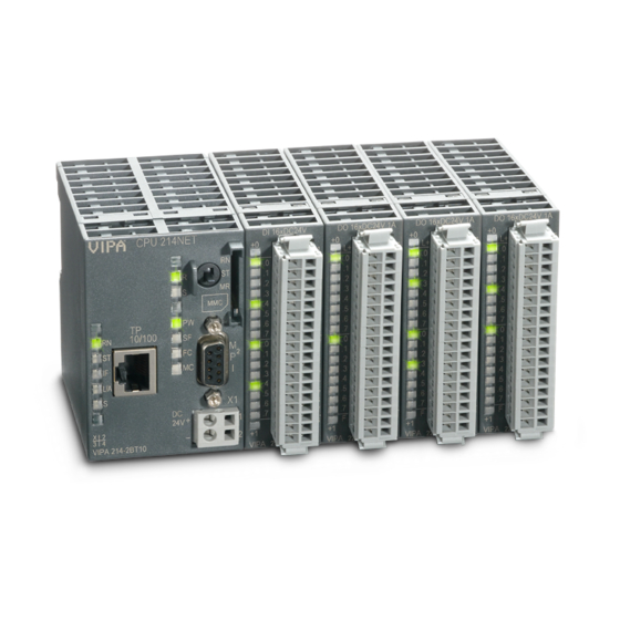
Manual VIPA System 200V Chapter 2 Hardware description Structure Operating mode switch Front view CPU 21xSER LEDs of the CPU 21xSER Slot for MMC memory card I interface Slot for DC 24V power supply LED of the RS232 interfaces RS232 interface COM1... - Page 30 Chapter 2 Hardware description Manual VIPA System 200V Power supply The CPU has an internal power supply. This is connected to an external supply voltage via two terminals located on the front of the unit. The power supply requires DC 24V (20.4 ... 28.8V). In addition to the electronic circuitry of the CPU this supply voltage is used for the modules connected to the backplane bus.
- Page 31 Manual VIPA System 200V Chapter 2 Hardware description The CPUs have an integrated work and a load memory. The memories are Memory battery-buffered. management Order number Work memory Load memory VIPA 214-2BS03 96kByte 144kByte VIPA 215-2BS03 128kByte 192kByte In the load memory there are program code and blocks stored together with the header information.
- Page 32 Chapter 2 Hardware description Manual VIPA System 200V The CPU has got LEDs on its front side. In the following the usage and the LEDs CPU according colors of the LEDs is described. Name Color Description green Indicates CPU power on.
-
Page 33: Technical Data
Manual VIPA System 200V Chapter 2 Hardware description Technical data 214-2BS03 Order no. 214-2BS03 Type CPU 214SER Technical data power supply Power supply (rated value) DC 24 V Power supply (permitted range) DC 20.4...28.8 V Reverse polarity protection Current consumption (no-load operation) - Page 34 Chapter 2 Hardware description Manual VIPA System 200V Order no. 214-2BS03 Number of FCs 1024 Maximum FC size 16 KB Number range FCs 0 ... 1023 Maximum nesting depth per priority class Maximum nesting depth additional within an error OB...
- Page 35 Manual VIPA System 200V Chapter 2 Hardware description Order no. 214-2BS03 Connector Sub-D, 9-pin, male Electrically isolated MP²I (MPI/RS232) Point-to-point interface Type COM2 Type of interface RS232 Connector Sub-D, 9-pin, male Electrically isolated MP²I (MPI/RS232) Point-to-point interface Functionality MPI Number of connections, max.
- Page 36 Chapter 2 Hardware description Manual VIPA System 200V 215-2BS03 Order no. 215-2BS03 Type CPU 215SER Technical data power supply Power supply (rated value) DC 24 V Power supply (permitted range) DC 20.4...28.8 V Reverse polarity protection Current consumption (no-load operation)
- Page 37 Manual VIPA System 200V Chapter 2 Hardware description Order no. 215-2BS03 Time Real-time clock buffered Clock buffered period (min.) 30 d Type of buffering Vanadium Rechargeable Lithium Batterie Load time for 50% buffering period 20 h Load time for 100% buffering period 48 h Accuracy (max.
- Page 38 Chapter 2 Hardware description Manual VIPA System 200V Order no. 215-2BS03 Type COM2 Type of interface RS232 Connector Sub-D, 9-pin, male Electrically isolated MP²I (MPI/RS232) Point-to-point interface Functionality MPI Number of connections, max. PG/OP channel Routing Global data communication S7 basic communication...
-
Page 39: Chapter 3 Deployment Cpu 21X-2Bs03
Manual VIPA System 200V Chapter 3 Deployment CPU 21x-2BS03 Chapter 3 Deployment CPU 21x-2BS03 Overview This chapter describes the deployment of the CPU in the System 200V. The description refers directly to the CPU and to the deployment in connection with peripheral modules, mounted on a profile rail together with the CPU at the backplane bus. -
Page 40: Assembly
Chapter 3 Deployment CPU 21x-2BS03 Manual VIPA System 200V Assembly Note! Information about assembly and cabling may be found at chapter "Basics and Assembly". Start-up behavior Turn on power When the CPU is delivered it has been reset. After the power supply has... -
Page 41: Addressing
Manual VIPA System 200V Chapter 3 Deployment CPU 21x-2BS03 Addressing Automatic To provide specific addressing of the installed peripheral modules, certain addressing addresses must be allocated in the CPU. The CPU contains a peripheral area (addresses 0 ... 1023) and a process image of the inputs and the outputs (for both each address 0 ... - Page 42 Chapter 3 Deployment CPU 21x-2BS03 Manual VIPA System 200V Example for auto- The following figure illustrates the automatic allocation of addresses: matic address allocation Slot: Peripheral area Peripheral area rel. Addr rel. Addr. Input byte 0 Output byte 0 Input byte 1...
-
Page 43: Hints For The Deployment Of The Mpi Interface
Manual VIPA System 200V Chapter 3 Deployment CPU 21x-2BS03 Hints for the deployment of the MPI interface What is MP The MP I jack combines 2 interfaces in 1: • MP interface • RS232 interface Please regard that the RS232 functionality is only available by using the Green Cable from VIPA. -
Page 44: Hardware Configuration - Cpu
• Go to Options > Install new GSD file • Navigate to the directory CPU21x and choose the corresponding file vipa_21x.gsd (German) or vipa_21x.gse (English) Now the modules of the VIPA System 200V are integrated in the hardware catalog PROFIBUS-DP... - Page 45 Manual VIPA System 200V Chapter 3 Deployment CPU 21x-2BS03 Proceeding To be compatible with the Siemens SIMATIC manager the following steps should be executed: • Start the hardware configurator from Siemens with a new project. Slot Module PROFIBUS (1): DP master system (1) •...
-
Page 46: Hardware Configuration - I/O Modules
Chapter 3 Deployment CPU 21x-2BS03 Manual VIPA System 200V Hardware configuration - I/O modules Hardware After the hardware configuration of the CPU place the System 200V configuration of modules in the plugged sequence. the modules In order to address the installed peripheral modules individually, specific addresses in the CPU have to be assigned to them. -
Page 47: Setting Cpu Parameters
Manual VIPA System 200V Chapter 3 Deployment CPU 21x-2BS03 Setting CPU parameters Parameterization Since the CPU from VIPA is to be configured as Siemens CPU 315-2DP via Siemens (315-2AF03 0AB00 V1.2) in the Siemens hardware configurator, the CPU 315-2AF03 parameters of the VIPA CPU may be set with "Object properties" of the CPU 315-2DP during hardware configuration. - Page 48 Chapter 3 Deployment CPU 21x-2BS03 Manual VIPA System 200V Monitoring time for This operation specifies the maximum time for the ready message of every ready message by configured module after PowerON. Here connected PROFIBUS DP slaves modules [100ms] are also considered until they are parameterized. If the modules do not...
- Page 49 Manual VIPA System 200V Chapter 3 Deployment CPU 21x-2BS03 Retentive Memory Number of Memory Enter the number of retentive memory bytes from memory byte 0 onwards. Bytes from MB0 Number of S7 Enter the number of retentive S7 timers from T0 onwards. Each S7 timer Timers from T0 occupies 2bytes.
- Page 50 Chapter 3 Deployment CPU 21x-2BS03 Manual VIPA System 200V Execution Enter the time intervals in ms, in which the watchdog interrupt OBs should be processed. The start time for the clock is when the operating mode switch is moved from STOP to RUN.
-
Page 51: Project Transfer
Manual VIPA System 200V Chapter 3 Deployment CPU 21x-2BS03 Project transfer Overview There are the following possibilities for project transfer into the CPU: • Transfer via MPI • Transfer via MMC when using a MMC programmer The structure of a MPI net is electrically identical with the structure of a Transfer via MPI PROFIBUS net. - Page 52 Chapter 3 Deployment CPU 21x-2BS03 Manual VIPA System 200V Configure MPI Hints for configuring a MPI interface are to find in the documentation of your programming software. The "Green Cable" has the order number VIPA 950-0KB00. Attention! Please regard, that you may use the "Green Cable" exclusively at VIPA...
- Page 53 Manual VIPA System 200V Chapter 3 Deployment CPU 21x-2BS03 Hints for the The Green Cable is a green connection cable, manufactured exclusively for Green Cable the deployment at VIPA System components. The Green Cable is a programming and download cable for VIPA CPUs I jack and VIPA field bus masters.
- Page 54 Chapter 3 Deployment CPU 21x-2BS03 Manual VIPA System 200V The MMC (Memory Card) serves as external transfer and storage medium. Transfer via There may be stored several projects and sub-directories on a MMC storage module. Please regard that your current project is stored in the root directory and has one of the following file names: •...
-
Page 55: Operating Modes
Manual VIPA System 200V Chapter 3 Deployment CPU 21x-2BS03 Operating modes Overview The CPU can be in one of 3 operating modes: • Operating mode STOP • Operating mode START-UP • Operating mode RUN Certain conditions in the operating modes START-UP and RUN require a specific reaction from the system program. - Page 56 Chapter 3 Deployment CPU 21x-2BS03 Manual VIPA System 200V Function security The CPUs include security mechanisms like a watchdog (100ms) and a parameterizable cycle time surveillance (parameterizable min. 1ms) that stop res. execute a RESET at the CPU in case of an error and set it into a defined STOP state.
-
Page 57: Overall Reset
Manual VIPA System 200V Chapter 3 Deployment CPU 21x-2BS03 Overall reset Overview During the overall reset the entire user memory is erased. Data located in the memory card is not affected. You have 2 options to initiate an overall reset: •... - Page 58 Chapter 3 Deployment CPU 21x-2BS03 Manual VIPA System 200V Automatic reload If there is a project S7PROG.WLD on the MMC, the CPU attempts to reload this project from MMC → the MC LED is on. When the reload has been completed the LED is extinguished. The operating mode of the CPU will be STOP or RUN, depending on the position of the function selector.
-
Page 59: Firmware Update
Manual VIPA System 200V Chapter 3 Deployment CPU 21x-2BS03 Firmware update Overview There is the opportunity to execute a firmware update for the CPU and its components via . For this an accordingly prepared MMC must be in the CPU during the startup. - Page 60 Chapter 3 Deployment CPU 21x-2BS03 Manual VIPA System 200V Attention! When installing a new firmware you have to be extremely careful. Under certain circumstances you may destroy the CPU, for example if the voltage supply is interrupted during transfer or if the firmware file is defective.
-
Page 61: Factory Reset
Manual VIPA System 200V Chapter 3 Deployment CPU 21x-2BS03 Factory reset Proceeding With the following proceeding the internal RAM of the CPU is completely deleted and the CPU is reset to delivery state. Please note that here also the MPI address is reset to the address 2! 1. -
Page 62: Vipa Specific Diagnostic Entries
Chapter 3 Deployment CPU 21x-2BS03 Manual VIPA System 200V VIPA specific diagnostic entries Entries in the You may read the diagnostic buffer of the CPU via the Siemens SIMATIC diagnostic buffer manager. Besides of the standard entries in the diagnostic buffer, the VIPA CPUs support some additional specific entries in form of event-IDs. - Page 63 Manual VIPA System 200V Chapter 3 Deployment CPU 21x-2BS03 Overview of the Event-IDs Event-ID Description 0xE003 Error at access to I/O devices Zinfo1: I/O address Zinfo2: Slot 0xE004 Multiple parameterization of a I/O address Zinfo1: I/O address Zinfo2: Slot 0xE005 Internal error –...
-
Page 64: Using Test Functions For Control And Monitoring Of Variables
Chapter 3 Deployment CPU 21x-2BS03 Manual VIPA System 200V Using test functions for control and monitoring of variables Overview For troubleshooting purposes and to display the status of certain variables you can access certain test functions via the menu item Debug of the Siemens SIMATIC manager. - Page 65 Manual VIPA System 200V Chapter 3 Deployment CPU 21x-2BS03 PLC > This test function returns the condition of a selected operand (inputs, Monitor/Modify outputs, flags, data word, counters or timers) at the end of program- Variables execution. This information is obtained from the process image of the selected operands.
- Page 66 Chapter 3 Deployment CPU 21x-2BS03 Manual VIPA System 200V 3-28 HB97E - CPU - RE_21x-2BS03 - Rev. 15/16...
-
Page 67: Serial Communication
Manual VIPA System 200V Chapter 4 Serial communication Chapter 4 Serial communication Overview Content of this chapter is the usage of the serial RS232 interface of the CPU. Here you’ll find all information about the deployment of the serial interfaces of the CPU. -
Page 68: Fast Introduction
Chapter 4 Serial communication Manual VIPA System 200V Fast introduction General The CPU 21x-2BS03 provide serial interfacing facilities between the processes of different source and destination systems. The CPU has got 2 serial RS232 interfaces. The communication happens via handling blocks that are stored in the CPU as library. - Page 69 Manual VIPA System 200V Chapter 4 Serial communication Depending to the protocol the following handling blocks are used: ASCII STX/ETX RK512 Name 3964(R) SFC 230 SEND SFC 231 RECEIVE SFC 232 FETCH SFC 233 CONTROL SFC 234 RESET SFC 235...
-
Page 70: Protocols And Procedures
Chapter 4 Serial communication Manual VIPA System 200V Protocols and Procedures Overview The CPU supports the following protocols and Procedures: • ASCII communication • STX/ETX • 3964(R) with RK512 ASCII data communication is one of the simple forms of data exchange. - Page 71 Manual VIPA System 200V Chapter 4 Serial communication The 3964(R) procedure controls the data transfer of a point-to-point link 3964(R) between the CPU 21x-2BS03 and a communication partner. The procedure adds control characters to the message data during data transfer. These control characters may be used by the communication partner to verify the complete and error free receipt.
- Page 72 Chapter 4 Serial communication Manual VIPA System 200V 3964(R) with The RK512 is an extended form of the 3964(R) procedure. The difference RK512 is that a message header is sent ahead of the message data. The header contains data about the size, type and length of the message data.
- Page 73 Manual VIPA System 200V Chapter 4 Serial communication Timeout times The following time-outs apply : Acknowledgement delay time: (QVZ) = 2000 ms Character delay time: (ZVZ) = 220 ms The QVZ is monitored between STX and DLE and between BCC and DLE.
-
Page 74: Rs232 Interface
Chapter 4 Serial communication Manual VIPA System 200V RS232 interface • Interface compatible to the COM interface of a PC Properties • Protocols supported: ASCII, STX/ETX, 3964(R) and RK512 • Receive buffer of 1024Byte and send buffer with 1024Byte • The maximum telegram length is 1024Byte •... -
Page 75: Communication
Manual VIPA System 200V Chapter 4 Serial communication Communication Data communication is controlled by means of the handler blocks. Overview The CPU decides the type of data transfer depending on the parameterization. The standard modes use the SEND/RECEIVE blocks for order initialization and the "ALL"... - Page 76 Chapter 4 Serial communication Manual VIPA System 200V Programming The following text shows the approach of programming in easy steps: Start-up OB100: • Call SYNCHRON with SFC 235 and enter the wanted block size (Page frame basic address=0, Block size, PAFE) •...
-
Page 77: Initialize Interfaces
Manual VIPA System 200V Chapter 4 Serial communication Initialize interfaces The initialization of the interfaces happens in OB 100 and should be Overview executed with the following approach: • Call SYNCHRON with SFC 235 and enter the wanted block size (page frame basic address=0, block size, PAFE) •... - Page 78 Chapter 4 Serial communication Manual VIPA System 200V You may transfer parameters to the CP via SEND (SFC 230), ANR=201 SFC 230 - SEND and DB. with ANR=201 and Parameter-DB Please regard that a send command is only executed when the following conditions are met: •...
-
Page 79: Interface Parameters
Manual VIPA System 200V Chapter 4 Serial communication Interface parameters Parameter-DB The parameter transfer to the communication processor happens during structure runtime by using the SFC 230 with order no. 201. The parameters for the protocols have to be stored in a DB. - Page 80 Chapter 4 Serial communication Manual VIPA System 200V Additional Depending on the selected protocol the following parameters must also be parameters specified in the DB: depending on the protocol if PROTOCOL_ASCII: Data byte Type Designator Values Default Transmit channel 8, 9...
- Page 81 Manual VIPA System 200V Chapter 4 Serial communication if PROTOCOL_3964(R): Data byte Type Designator Values Default Transmit-/ receive channel 8, 9 WORD BufAnz 1 ... n 10, 11 WORD BufSize 16 ... 1024 128 12, 13 WORD ZNA, time delay after job 0 ...
-
Page 82: Interface Communication
Chapter 4 Serial communication Manual VIPA System 200V Interface communication The communication happens via the following handling blocks in the OB1: Overview Designator SFC 230 SEND Initialize a send order SFC 236 SEND-ALL Send user data SFC 231 RECEIVE Initialize a receive order... - Page 83 Manual VIPA System 200V Chapter 4 Serial communication SFC 236 - If the CP is able to take over the data directly, the SEND block transfers the SEND_ALL requested data in one session. If the CP requests only the order parameters or the amount of the depending data is too large, the CP only gets the sending parameters res.
- Page 84 Chapter 4 Serial communication Manual VIPA System 200V The FETCH block initializes a FETCH order in the partner station. SFC 232 - FETCH The FETCH order defines data source and destination and the data source is transmitted to the partner station.
Need help?
Do you have a question about the VIPA System 200V and is the answer not in the manual?
Questions and answers