
Subscribe to Our Youtube Channel
Related Manuals for YASKAWA IM 053PN


Summary of Contents for YASKAWA IM 053PN
- Page 1 VIPA System SLIO IM | 053-1PN00 | Manual HB300 | IM | 053-1PN00 | en | 19-08 Interface module PROFINET - IM 053PN www.vipa.com/en/service-support/manuals...
- Page 2 VIPA GmbH Ohmstr. 4 91074 Herzogenaurach Telephone: +49 9132 744-0 Fax: +49 9132 744-1864 Email: info@vipa.com Internet: www.vipa.com 053-1PN00_000_IM 053PN,3,EN - © 2019...
-
Page 3: Table Of Contents
VIPA System SLIO Table of contents Table of contents General........................5 1.1 Copyright © VIPA GmbH ................. 5 1.2 About this manual..................... 6 1.3 Safety information..................... 7 Basics and mounting..................... 8 2.1 Safety information for users................8 2.2 System conception................... 9 2.2.1 Overview...................... - Page 4 VIPA System SLIO Table of contents 4.7.2 Diagnostic interrupt..................64 4.8 I&M data......................71 4.9 Index overview....................73 HB300 | IM | 053-1PN00 | en | 19-08...
-
Page 5: General
VIPA System SLIO General Copyright © VIPA GmbH General 1.1 Copyright © VIPA GmbH All Rights Reserved This document contains proprietary information of VIPA and is not to be disclosed or used except in accordance with applicable agreements. This material is protected by the copyright laws. It may not be reproduced, distributed, or altered in any fashion by any entity (either internal or external to VIPA), except in accord- ance with applicable agreements, contracts or licensing, without the express written con- sent of VIPA and the business management owner of the material. -
Page 6: About This Manual
This manual describes the IM 053-1PN00 of the System SLIO from VIPA. It contains a description of the structure, project engineering and deployment. Product Order number as of state: IM 053PN 053-1PN00 V1.5.7 Target audience The manual is targeted at users who have a background in automation technology. -
Page 7: Safety Information
VIPA System SLIO General Safety information CAUTION! Damages to property is likely if these warnings are not heeded. Supplementary information and useful tips. 1.3 Safety information Applications conforming The system is constructed and produced for: with specifications communication and process control general control and automation tasks industrial applications operation within the environmental conditions specified in the technical data... -
Page 8: Basics And Mounting
VIPA System SLIO Basics and mounting Safety information for users Basics and mounting 2.1 Safety information for users Handling of electrostatic VIPA modules make use of highly integrated components in MOS-Technology. These sensitive modules components are extremely sensitive to over-voltages that can occur during electrostatic discharges. -
Page 9: System Conception
VIPA System SLIO Basics and mounting System conception > Overview 2.2 System conception 2.2.1 Overview System SLIO is a modular automation system for assembly on a 35mm mounting rail. By means of the peripheral modules with 2, 4 or 8 channels this system may properly be adapted matching to your automation tasks. -
Page 10: Components
VIPA System SLIO Basics and mounting System conception > Components 2.2.2 Components CPU (head module) Bus coupler (head module) Line extension Periphery modules Accessories CAUTION! Only modules of VIPA may be combined. A mixed operation with third- party modules is not allowed! CPU 01xC With this CPU 01xC, the CPU electronic, input/output components and power supply are integrated to one casing. - Page 11 VIPA System SLIO Basics and mounting System conception > Components Line extension In the System SLIO there is the possibility to place up to 64 modules in on line. By means of the line extension you can divide this line into several lines. Here you have to place a line extension master at each end of a line and the subsequent line has to start with a line extension slave.
-
Page 12: Accessories
VIPA System SLIO Basics and mounting System conception > Accessories 2.2.3 Accessories Shield bus carrier The shield bus carrier (order no.: 000-0AB00) serves to carry the shield bus (10mm x 3mm) to connect cable shields. Shield bus carriers, shield bus and shield fixings are not in the scope of delivery. -
Page 13: Hardware Revision
VIPA System SLIO Basics and mounting Dimensions 2.2.4 Hardware revision Hardware revision on the The hardware revision version is printed on every System SLIO module. front Since a System SLIO module consists of a terminal and electronics module, you will find a hardware revision on each of them. - Page 14 VIPA System SLIO Basics and mounting Dimensions Dimensions CPU 01x Dimensions bus coupler and line extension slave Dimensions line extension master HB300 | IM | 053-1PN00 | en | 19-08...
-
Page 15: Mounting Bus Coupler
VIPA System SLIO Basics and mounting Mounting bus coupler Dimension periphery module Dimensions electronic module Dimensions in mm 2.4 Mounting bus coupler Requirements for UL compliance use – Use for power supply exclusively SELV/PELV power supplies. – The System SLIO must be installed and operated in a housing according to IEC 61010-1 9.3.2 c). - Page 16 VIPA System SLIO Basics and mounting Mounting bus coupler Proceeding Mount the mounting rail! Please consider that a clearance from the middle of the mounting rail of at least 80mm above and 60mm below, respectively 80mm by deployment of shield bus carriers, exist. Turn the locking lever upwards, place the bus coupler at the mounting rail and turn the lever downward.
- Page 17 VIPA System SLIO Basics and mounting Mounting bus coupler Mounting periphery modules Before mounting the periphery modules you have to remove the bus cover at the right side of the bus coupler by pulling it forward. Keep the cover for later mounting. Mount the periphery modules you want.
-
Page 18: Wiring
VIPA System SLIO Basics and mounting Wiring > Wiring bus coupler 2.5 Wiring CAUTION! Consider temperature for external cables! Cables may experience temperature increase due to system heat dissi- pation. Thus the cabling specification must be chosen 5°C above ambient temperature! CAUTION! Separate insulation areas! - Page 19 VIPA System SLIO Basics and mounting Wiring > Wiring bus coupler Wiring procedure Pin number at the connector Opening for screwdriver Connection hole for wire Insert a suited screwdriver at an angel into the square opening as shown. Press and hold the screwdriver in the opposite direction to open the contact spring. Insert the stripped end of wire into the round opening.
- Page 20 VIPA System SLIO Basics and mounting Wiring > Wiring bus coupler PM - Power module For wires with a core cross-section of 0.08mm up to 1.5mm Pos. Function Type Description not connected DC 24V DC 24V for power section supply GND for power section supply Sys DC 24V DC 24V for electronic section supply...
-
Page 21: Wiring Periphery Modules
VIPA System SLIO Basics and mounting Wiring > Wiring periphery modules Shield attachment Shield bus carrier Shield bus (10mm x 3mm) Shield clamp Cable shield To attach the shield the mounting of shield bus carriers are necessary. The shield bus carrier (available as accessory) serves to carry the shield bus to connect cable shields. - Page 22 VIPA System SLIO Basics and mounting Wiring > Wiring periphery modules Data 240V AC / 30V DC Cross section 0.08 ... 1.5mm (AWG 28 ... 16) Stripping length 10mm Wiring procedure Pin number at the connector Opening for screwdriver Connection hole for wire Insert a suited screwdriver at an angel into the square opening as shown.
-
Page 23: Wiring Power Modules
VIPA System SLIO Basics and mounting Wiring > Wiring power modules Attach the cables with the accordingly stripped cable screen and fix it by the shield clamp with the shield bus. 2.5.3 Wiring power modules Terminal module terminals Power modules are either integrated to the head module or may be installed between the periphery modules. - Page 24 VIPA System SLIO Basics and mounting Wiring > Wiring power modules Wiring procedure Pin number at the connector Opening for screwdriver Connection hole for wire Insert a suited screwdriver at an angel into the square opening as shown. Press and hold the screwdriver in the opposite direction to open the contact spring. Insert the stripped end of wire into the round opening.
- Page 25 VIPA System SLIO Basics and mounting Wiring > Wiring power modules PM - Power module For wires with a core cross-section of 0.08mm up to 1.5mm Pos. Function Type Description not connected DC 24V DC 24V for power section supply GND for power section supply Sys DC 24V DC 24V for electronic section supply...
- Page 26 VIPA System SLIO Basics and mounting Wiring > Wiring power modules Deployment of the power If the 10A for the power section supply is no longer sufficient, you may use the power modules module from VIPA with the order number 007-1AB00. So you have also the possibility to define isolated groups.
-
Page 27: Demounting
VIPA System SLIO Basics and mounting Demounting > Demounting bus coupler Shield attachment Shield bus carrier Shield bus (10mm x 3mm) Shield clamp Cable shield To attach the shield the mounting of shield bus carriers are necessary. The shield bus carrier (available as accessory) serves to carry the shield bus to connect cable shields. - Page 28 VIPA System SLIO Basics and mounting Demounting > Demounting bus coupler For demounting and exchange of a (head) module or a group of modules, due to mounting reasons you always have to remove the electronic module right beside. After mounting it may be plugged again.
-
Page 29: Demounting Periphery Modules
VIPA System SLIO Basics and mounting Demounting > Demounting periphery modules Plug again the electronic module, which you have removed before. Wire your bus coupler. ð Now you can bring your system back into operation. 2.6.2 Demounting periphery modules Proceeding Exchange of an electronic Power-off your system. - Page 30 VIPA System SLIO Basics and mounting Demounting > Demounting periphery modules Turn the locking lever of the module to be exchanged upwards. Pull the module. For mounting turn the locking lever of the module to be mounted upwards. To mount the module put it to the gap between the both modules and push it, guided by the stripes at both sides, to the mounting rail.
- Page 31 VIPA System SLIO Basics and mounting Demounting > Demounting periphery modules Turn all the locking lever of the module group to be exchanged upwards. Pull the module group forward. For mounting turn all the locking lever of the module group to be mounted upwards. To mount the module group put it to the gap between the both modules and push it, guided by the stripes at both sides, to the mounting rail.
-
Page 32: Trouble Shooting - Leds
VIPA System SLIO Basics and mounting Trouble shooting - LEDs 2.7 Trouble shooting - LEDs General Each module has the LEDs RUN and MF on its front side. Errors or incorrect modules may be located by means of these LEDs. In the following illustrations flashing LEDs are marked by ☼. -
Page 33: Installation Guidelines
VIPA System SLIO Basics and mounting Installation guidelines 2.8 Installation guidelines General The installation guidelines contain information about the interference free deployment of a PLC system. There is the description of the ways, interference may occur in your PLC, how you can make sure the electromagnetic compatibility (EMC), and how you manage the isolation. - Page 34 VIPA System SLIO Basics and mounting Installation guidelines Proof the correct fixing of the lead isolation. – Data lines must be laid isolated. – Analog lines must be laid isolated. When transmitting signals with small ampli- tudes the one sided laying of the isolation may be favourable. –...
-
Page 35: General Data
VIPA System SLIO Basics and mounting General data 2.9 General data Conformity and approval Conformity 2014/35/EU Low-voltage directive 2014/30/EU EMC directive Approval Refer to Technical data others RoHS 2011/65/EU Restriction of the use of certain hazardous substances in electrical and electronic equipment Protection of persons and device protection Type of protection IP20... - Page 36 VIPA System SLIO Basics and mounting General data Mounting conditions Mounting place In the control cabinet Mounting position Horizontal and vertical Standard Comment Emitted interference EN 61000-6-4 Class A (Industrial area) Noise immunity EN 61000-6-2 Industrial area zone B EN 61000-4-2 8kV at air discharge (degree of severity 3), 4kV at contact discharge (degree of severity 2) EN 61000-4-3...
-
Page 37: Hardware Description
Supports FMM (Free Module Mapping) Supports multiple and single write (acyclic communication) Integrated Web server Integrated DHCP client Ordering data Type Order number Description IM 053PN 053-1PN00 PROFINET IO device for System SLIO HB300 | IM | 053-1PN00 | en | 19-08... -
Page 38: Structure
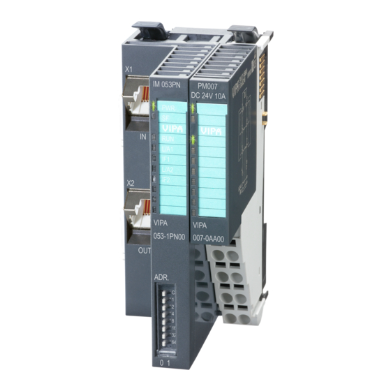
VIPA System SLIO Hardware description Structure > Interfaces 3.2 Structure 053-1PN00 Locking lever terminal module Labeling strip bus interface LED status indication bus interface Labeling strip power module LED status indication power module Backplane bus DC 24V power section supply Power module X1: PROFINET RJ45 bus interface "P1"... -
Page 39: Leds
VIPA System SLIO Hardware description Structure > LEDs PM - Power module For wires with a core cross-section of 0.08mm up to 1.5mm Pos. Function Type Description not connected DC 24V DC 24V for power section supply GND for power section supply Sys DC 24V DC 24V for electronic section supply not connected... - Page 40 VIPA System SLIO Hardware description Structure > LEDs LNK1 ACT1 LNK2 ACT2 Description green yellow green green green green The PROFINET IO device is power sup- plied. No connection can be established to the PROFINET IO controller, but there is a connection to the switch (no AR is 0.5Hz active).
-
Page 41: Address Switch
VIPA System SLIO Hardware description Structure > Address switch 3.2.3 Address switch Address switch – A PROFINET name may only once exist on the bus! Changes of the address switch were only recognized after PowerON or a Reset! – The PROFINET name preset at the address switch must always be identical to the device name in your project! The address switch serves for the following settings: Selection of the address usage... - Page 42 VIPA System SLIO Hardware description Structure > Address switch Position State Behavior at start-up 2 ... 8 PROFINET compliant (IEC 61158-6-10, IEC 61784-2) PROFINET name (device name) respectively IP address parameter come from flash memory. Here the device name may be free selected. Please regard that you have to assign the device name respectively the IP address to the PROFINET device by means of an initialization.
-
Page 43: Technical Data
VIPA System SLIO Hardware description Technical data 3.3 Technical data Order no. 053-1PN00 Type IM 053PN Module ID Technical data power supply Power supply (rated value) DC 24 V Power supply (permitted range) DC 20.4...28.8 V Reverse polarity protection ü... - Page 44 VIPA System SLIO Hardware description Technical data Order no. 053-1PN00 Number of participants, max. Node addresses Transmission speed, min. 100 Mbit/s Transmission speed, max. 100 Mbit/s Address range inputs, max. 512 Byte Address range outputs, max. 512 Byte Number of TxPDOs, max. Number of RxPDOs, max.
-
Page 45: Deployment
VIPA System SLIO Deployment Basics PROFINET Deployment 4.1 Basics PROFINET General PROFINET is an open Industrial Ethernet Standard from PROFIBUS & PROFINET International (PI) for automation. PROFINET is standardized in the IEC 61158. PROFINET uses TCP/IP and IT standards and supplements the PROFIBUS tech- nology for applications, where fast data communication with industrial IT functions is demanded. - Page 46 VIPA System SLIO Deployment Basics PROFINET Properties of PROFINET PROFINET of IEC 61158 has the following properties: Full-duplex transfer with 100MBit/s via copper respectively fibre optics. Switched Ethernet Auto negotiation (negotiates the transfer parameters) Auto crossover (transmission and receipt lines are crossed automatically if neces- sary) Wireless communication via WLAN UDP/IP is used as overlaid protocol.
-
Page 47: Profinet Installation Guidelines
VIPA System SLIO Deployment PROFINET installation guidelines GSDML file To configure a device I/O connection in your own configuration tool, you’ve got all the information about your PROFINET components in form of a GSDML file. This file may be found for System SLIO in the download area of www.vipa.com at ‘Config files è... - Page 48 VIPA System SLIO Deployment PROFINET installation guidelines Industrial Ethernet Due to the open standard of PROFINET standard Ethernet components may be used. For industrial environment and due to the high transfer rate of 100MBit/s you PROFINET system should consist of Industrial Ethernet components. All the devices interconnected by switches are located in one and the same network.
-
Page 49: Accessing The System Slio
VIPA System SLIO Deployment Accessing the System SLIO > Overview 4.3 Accessing the System SLIO 4.3.1 Overview Information concerning the allocation of these areas may be found in the description of the corresponding System SLIO module. In the following you will find the description of accessing the following System SLIO areas via PROFINET: I/O area Parameter data... -
Page 50: Accessing The I/O Area
VIPA System SLIO Deployment Accessing the System SLIO > Accessing the parameter data 4.3.2 Accessing the I/O area At PROFINET the input respectively output area is automatically embedded to the corresponding address area of the master system. By means of the handling block SFB 52 - RDREC the I/O area can be acyclically accessed via the following index numbers: –... -
Page 51: Accessing Diagnostics Data
VIPA System SLIO Deployment Project engineering 4.3.4 Accessing diagnostics data Hardware interrupt data – Hardware interrupt data of System SLIO modules with interrupt capability were automatically sent by a diagnostics message if the interrupt is activated by para- metrization at the corresponding module respectively at the System SLIO PROFINET IO device. - Page 52 VIPA System SLIO Deployment Project engineering Name of the device So that the PROFINET controller can identify a PROFINET device, you have to assign an appropriate device name to the PROFINET device, before. This name must be always identical to the device name in your project! To assign a device name there is an address switch on the PROFINET device.
- Page 53 VIPA System SLIO Deployment Project engineering Position State Behavior at start-up 2 ... 8 PROFINET compliant (IEC 61158-6-10, IEC 61784-2) PROFINET name (device name) respectively IP address parameter come from flash memory. Here the device name may be free selected. Please regard that you have to assign the device name respectively the IP address to the PROFINET device by means of an initialization.
-
Page 54: Parameter Data
VIPA System SLIO Deployment Project engineering > Parameter data For parametrization of the PROFINET device the VIPA specific properties dialog may be opened in the slot overview . Insert the peripheral modules from the hardware catalog and parametrize them if necessary. - Page 55 VIPA System SLIO Deployment Project engineering > Parameter data Diagnostic interrupt type Here the structure of the diagnostic interrupt data may be defined, which were sent on error via diagnostic telegram respectively which may be requested by the standard PROFINET Index numbers. –...
-
Page 56: Web Server
VIPA System SLIO Deployment Web server 4.5 Web server Please consider the System SLIO power and clamp modules do not have any module ID. These may not be recognized by the PROFINET IO device and so are not listed respectively considered during slot allocation. Access via IP address On delivery the PROFINET IO device has no IP address. - Page 57 VIPA System SLIO Deployment Web server Web server with selected PROFINET IO device Info – Here order number, serial number and the version of firmware and hardware of the PROFINET IO device are listed. Data – The PROFINET IO device hast no data. Parameter –...
-
Page 58: Free Module Mapping (Fmm)
VIPA System SLIO Deployment Free Module Mapping (FMM) > Overview 4.6 Free Module Mapping (FMM) 4.6.1 Overview With FMM you can use PROFINET IO devices with different hardware variants without adapting your user program. You only have to adapt the FMM configuration in the PROFINET IO device when configuring the hardware variants. -
Page 59: Fmm Configuration
VIPA System SLIO Deployment Free Module Mapping (FMM) > FMM configuration 4.6.2 FMM configuration Configuration The mapping of the modules is defined as configuration by the 64byte record set 0x7F. The record set is remanent stored in the PROFINET IO device, but not sent from the PROFINET controller to the IO device during the connection setup. -
Page 60: Examples
VIPA System SLIO Deployment Free Module Mapping (FMM) > Examples For commissioning, you have to activate the parameter ‘Startup when expected/ actual configuration differs’ because during the commissioning without FMM, the IO device responds to the CPU with a 1:1 mapping. Create in your machine application for the configuration record set a memory area, which can be accordingly manipulated by the user program and transferred to your IO device. - Page 61 VIPA System SLIO Deployment Free Module Mapping (FMM) > Examples 4.6.3.2 Examples of hardware variants Based on the target configuration, the following examples show how to determine the FMM values for the hardware variants. Variant 1: Same type and number of modules but reversed slots (1): Target configuration Slot Module...
- Page 62 VIPA System SLIO Deployment Free Module Mapping (FMM) > Examples Variant 2: Reversed slots and modules are missing (1): Target configuration Slot Module Slot Module target target actual actual (2): Actual configuration Determination of FMM Slot 1: The module of Slot = 1 is in the actual configuration at Slot = 1 àFMM = 1 target...
- Page 63 VIPA System SLIO Deployment Free Module Mapping (FMM) > Examples Variant 3: Modules are ignored (1): Target configuration Slot Module Slot Module target target actual actual (2): Actual configuration empty empty Determination of FMM Slot 1: The module of Slot = 1 is ignored in the actual configuration à...
-
Page 64: Hardware And Diagnostic Interrupt
VIPA System SLIO Deployment Hardware and diagnostic interrupt > Diagnostic interrupt 4.7 Hardware and diagnostic interrupt 4.7.1 Hardware interrupt Hardware interrupt data of System SLIO modules with interrupt capability were auto- matically sent by a diagnostics message if the interrupt is activated by parametriza- tion at the corresponding module respectively at the System SLIO PROFINET IO device. - Page 65 VIPA System SLIO Deployment Hardware and diagnostic interrupt > Diagnostic interrupt UserSpecified Diagnostics (vendor specific) Byte Description Example Content 0..1 AlarmNotification 0001h PROFINET interrupt data (header) 1: High 2: Low 2..3 BlockLength 0030h 4..5 Version High/Low 0100h 6..7 AlarmType 0001h 1: Diagnostics 2: Process 3: Pull...
- Page 66 VIPA System SLIO Deployment Hardware and diagnostic interrupt > Diagnostic interrupt Byte Description Example Content 6..7 AlarmType Example 1: Diagnostics 2: Process 3: Pull 8..11 0000h, 0000h 12..13 Slot 0001h 14..15 Subslot 0001h 16..19 ModuleIdentNumber 0403h, 1543h 20..23 SubmoduleIdentNumber 0000h, 0001h 24..25 DiagnosticsState A807h...
- Page 67 VIPA System SLIO Deployment Hardware and diagnostic interrupt > Diagnostic interrupt Code Description 0010h Parametrization error 0011h Sensor or load voltage missing 0012h Fuse defect 0013h Communication errors 0014h Ground fault 0015h Reference channel error 0016h Hardware interrupt lost 0017h Threshold interrupt 0018h The outputs are disabled...
- Page 68 VIPA System SLIO Deployment Hardware and diagnostic interrupt > Diagnostic interrupt Structure Byte Bit 7 ... Bit 0 Diagnostic byte 1 Bit 0: Error on System SLIO bus Bit 1: Parameter could not be written into the IO device. Bit 2: General parameter error IO device. Bit 3: Version error at the System SLIO bus (at least one module is not supported at the System SLIO bus).
- Page 69 VIPA System SLIO Deployment Hardware and diagnostic interrupt > Diagnostic interrupt Name Bytes Function CHxERR Channel-specific error channel x DIAG_US µs ticker ERR_A Diagnostic Byte Bit 7 ... 0 Bit 0: set at module failure Bit 1: reserved Bit 2: set at external error Bit 3: set at channel error Bit 4: set at external auxiliary supply missing Bit 6 ...
- Page 70 VIPA System SLIO Deployment Hardware and diagnostic interrupt > Diagnostic interrupt NUMCH Channels Byte Bit 7 ... 0 Number of channels of a module. CHERR Channel error Byte Bit 7 ... 0 Bit 0: set at error in channel 0 Bit 1: set at error in channel 1 Bit 2: set at error in channel 2 Bit 3: set at error in channel 3...
-
Page 71: I&M Data
VIPA System SLIO Deployment I&M data 4.8 I&M data Overview I&M data are Identification and Maintenance data. These data are stored in the module which support you at: – Check of the system configuration – Discover of hardware changes of a plant –... - Page 72 VIPA System SLIO Deployment I&M data I&M data for PROFINET-IO Identification data Access Preset Explanation Identification data 0: (Index AFF0h) VendorIDHigh read (1byte) Name of the manufacturer (555 = VIPA GmbH) VendorIDLow read (1byte) Order_ID read (20byte) Order number IM_SERIAL_NUMBER read (16byte) Serial number IM_HARDWARE_REVISION...
-
Page 73: Index Overview
VIPA System SLIO Deployment Index overview 4.9 Index overview General Within a module the I/O, parameter and diagnostics data may be accessed by Index numbers. In PROFINET the Index numbers are grouped to the following areas: – 0000h ... 7FFFh: Vendor-specific Index numbers –... - Page 74 VIPA System SLIO Deployment Index overview Index Description Ä Chap. 4.6 ‘Free Module Map- 007Fh* write FMM configuration ping (FMM)’ page 58 007Fh** write DS 01h of the parameter data 0080h … 0090h ** write DS 80h ... DS 90h of the parameter data AFF1h * write I&M 1 (identification and location) AFF2h *...
Need help?
Do you have a question about the IM 053PN and is the answer not in the manual?
Questions and answers