
Related Manuals for YASKAWA VIPA System MICRO


Summary of Contents for YASKAWA VIPA System MICRO
- Page 1 VIPA System MICRO CPU | M13-CCF0000 | Manual HB400 | CPU | M13-CCF0000 | en | 18-50 SPEED7 CPU M13C www.vipa.com/en/service-support/manuals...
- Page 2 VIPA GmbH Ohmstr. 4 91074 Herzogenaurach Telephone: 09132-744-0 Fax: 09132-744-1864 Email: info@vipa.com Internet: www.vipa.com M13-CCF0000_000_CPU M13C,5,EN - © 2018...
-
Page 3: Table Of Contents
VIPA System MICRO Table of contents Table of contents General........................8 1.1 Copyright © VIPA GmbH ................. 8 1.2 About this manual..................... 9 1.3 Safety information................... 10 Basics and mounting................... 11 2.1 Safety information for users................11 2.2 System conception..................12 2.3 Dimensions..................... - Page 4 VIPA System MICRO Table of contents 4.7.1 Parameterization via Siemens CPU............76 4.7.2 Parameter CPU................... 77 4.8 Setting VIPA specific CPU parameters............80 4.9 Project transfer....................81 4.9.1 Transfer via Ethernet................... 81 4.9.2 Transfer via memory card................82 4.9.3 Option: Transfer via MPI................82 4.10 Accessing the web server................
- Page 5 VIPA System MICRO Table of contents 5.6.7 Diagnostics and interrupt................139 5.7 Frequency measurement................140 5.7.1 Properties....................140 5.7.2 Wiring......................141 5.7.3 Proceeding....................142 5.7.4 Parametrization..................142 5.7.5 Status indication..................144 5.8 Pulse width modulation - PWM..............146 5.8.1 Properties....................146 5.8.2 Wiring......................
- Page 6 VIPA System MICRO Table of contents 7.7 Device replacement without exchangeable medium/PG......195 7.8 Commissioning and start-up behavior............196 7.9 PROFINET diagnostics................197 7.9.1 Overview....................197 7.9.2 Diagnostics with the configuration and engineering tool......197 7.9.3 Diagnostics during runtime in the user program........197 7.9.4 Diagnostics via OB start information............
- Page 7 VIPA System MICRO Table of contents 10.8 SPEED7 Studio - Project transfer............... 254 10.8.1 Transfer via MPI..................254 10.8.2 Transfer via Ethernet................256 10.8.3 Transfer via memory card................ 257 Configuration with TIA Portal................258 11.1 TIA Portal - Work environment ..............258 11.1.1 General....................
-
Page 8: General
VIPA System MICRO General Copyright © VIPA GmbH General 1.1 Copyright © VIPA GmbH All Rights Reserved This document contains proprietary information of VIPA and is not to be disclosed or used except in accordance with applicable agreements. This material is protected by the copyright laws. It may not be reproduced, distributed, or... -
Page 9: About This Manual
VIPA System MICRO General About this manual Information product sup- Contact your local VIPA Customer Service Organization representative if you wish to port report errors or questions regarding the contents of this document. If you are unable to locate a customer service centre, contact VIPA as follows: VIPA GmbH, Ohmstraße 4, 91074 Herzogenaurach, Germany... -
Page 10: Safety Information
VIPA System MICRO General Safety information CAUTION! Damages to property is likely if these warnings are not heeded. Supplementary information and useful tips. 1.3 Safety information Applications conforming The system is constructed and produced for: with specifications communication and process control... -
Page 11: Basics And Mounting
VIPA System MICRO Basics and mounting Safety information for users Basics and mounting 2.1 Safety information for users Handling of electrostatic VIPA modules make use of highly integrated components in MOS-Technology. These sensitive modules components are extremely sensitive to over-voltages that can occur during electrostatic discharges. -
Page 12: System Conception
VIPA System MICRO Basics and mounting System conception 2.2 System conception Overview The System MICRO is a modular automation system for assembly on a 35mm mounting rail. By means of periphery modules this system may be adapted matching to your auto- mation tasks. -
Page 13: Dimensions
VIPA System MICRO Basics and mounting Dimensions Periphery module By means of up to 8 periphery modules, you can extend the internal I/O areas. The attachment to the CPU is made by plugging them on the right side of the CPU. -
Page 14: Mounting
VIPA System MICRO Basics and mounting Mounting > Mounting CPU Dimensions periphery module Dimensions in mm 2.4 Mounting 2.4.1 Mounting CPU 2.4.1.1 Mounting CPU without mounting rail CAUTION! Mounting without mounting rail is only permitted, if you only want to use the CPU without extension and periphery modules. - Page 15 VIPA System MICRO Basics and mounting Mounting > Mounting CPU Proceeding You can screw the CPU to the back wall by means of screws via the locking levers. This happens with the following proceeding: Dimensions in mm The CPU has a locking lever on the upper and lower side. Pull these levers out- wards as shown in the figure, until these engage 2x audible.
- Page 16 VIPA System MICRO Basics and mounting Mounting > Mounting CPU The CPU has a locking lever on the upper and lower side. Pull these levers out- wards as shown in the figure, until these engage audible. CAUTION! It is not allowed to mount the module sideways on the mounting rail, as otherwise the module may be damaged.
-
Page 17: Mounting The Extension Module
VIPA System MICRO Basics and mounting Mounting > Mounting the extension module 2.4.2 Mounting the extension module Proceeding You have the possibility to extend the interfaces of the CPU by plugging an extension module. For this the extension module is plugged at the left side of the CPU. The mount- ings happens with the following proceeding: Remove the bus cover with a screwdriver on the left side of the CPU. -
Page 18: Mounting Periphery Module
VIPA System MICRO Basics and mounting Mounting > Mounting periphery module 2.4.3 Mounting periphery module Proceeding You have the possibility to extend the periphery area of the CPU by plugging up to 8 periphery modules. For this the periphery modules are plugged at the right side of the CPU. -
Page 19: Wiring
VIPA System MICRO Basics and mounting Wiring > Wiring CPU 2.5 Wiring CAUTION! Consider temperature for external cables! Cables may experience temperature increase due to system heat dissi- pation. Thus the cabling specification must be chosen 5°C above ambient temperature! - Page 20 VIPA System MICRO Basics and mounting Wiring > Wiring CPU Remove wire The wire is to be removed by means of a screwdriver with 2.5mm blade width. Press with your screwdriver vertically at the release button. ð The contact spring releases the wire.
- Page 21 VIPA System MICRO Basics and mounting Wiring > Wiring CPU (1) X2: 4L+: DC 24V power section supply for integrated outputs X1: 3L+: DC 24V power section supply for integrated inputs (2) X6: 1L+ DC 24V for electronic power supply The electronic power section supply is internally protected against higher voltage by fuse.
- Page 22 VIPA System MICRO Basics and mounting Wiring > Wiring CPU Push the screwdriver backwards: ð The connector is unlocked and can be removed. CAUTION! Via wrong operation such as pressing the screwdriver down- ward, the release lever may be damaged.
-
Page 23: Wiring Periphery Module
VIPA System MICRO Basics and mounting Wiring > Wiring periphery module 2.5.2 Wiring periphery module Periphery module con- For wiring the periphery module has removable connectors. With the wiring of the con- nector nectors a "push-in" spring-clip technique is used. This allows a quick and easy connection of your signal and supply lines. - Page 24 VIPA System MICRO Basics and mounting Wiring > Wiring periphery module Remove connector By means of a screwdriver there is the possibility to remove the connectors e.g. for module exchange with a fix wiring. For this each connector has indentations for unlocking at the top.
-
Page 25: Demounting
VIPA System MICRO Basics and mounting Demounting > Demounting CPU 2.6 Demounting 2.6.1 Demounting CPU Remove connector By means of a screwdriver there is the possibility to remove the connectors e.g. for module exchange with a fix wiring. For this each connector has indentations for unlocking at the top. - Page 26 VIPA System MICRO Basics and mounting Demounting > Demounting CPU Pull the locking levers of the CPU outwards until these engage audible. CAUTION! It is not allowed to mount the module sideways on the mounting rail, as otherwise the module may be damaged! Plug the CPU from the top onto the mounting rail and turn the CPU downward until it rests on the mounting rail.
- Page 27 VIPA System MICRO Basics and mounting Demounting > Demounting CPU Plug again the wired connectors. ð Now you can bring your system back into operation. Option: CPU replacement In the following the replacement of a CPU in a system is shown:...
- Page 28 VIPA System MICRO Basics and mounting Demounting > Demounting CPU Rebind your modules by moving the CPU along with the extension module on the mounting rail. To fix the CPU at the mounting rail, move the locking levers back to the initial posi- tion.
-
Page 29: Demounting The Extension Module
VIPA System MICRO Basics and mounting Demounting > Demounting the extension module 2.6.2 Demounting the extension module Proceeding Power-off your system. Remove the corresponding bus connectors. Use a screwdriver to pull the locking levers of the extension module outwards until these engage audible. -
Page 30: Demounting Periphery Module
VIPA System MICRO Basics and mounting Demounting > Demounting periphery module 2.6.3 Demounting periphery module Remove connector By means of a screwdriver there is the possibility to remove the connectors e.g. for module exchange with a fix wiring. For this each connector has indentations for unlocking at the top. - Page 31 VIPA System MICRO Basics and mounting Demounting > Demounting periphery module Remove the periphery module with a rotation upwards from the mounting rail. Pull the locking levers outwards until these engage audible. CAUTION! It is not allowed to mount the module sideways on the mounting rail,...
- Page 32 VIPA System MICRO Basics and mounting Demounting > Demounting periphery module Plug again the wired connectors. ð Now you can bring your system back into operation. HB400 | CPU | M13-CCF0000 | en | 18-50...
-
Page 33: Installation Guidelines
VIPA System MICRO Basics and mounting Installation guidelines 2.7 Installation guidelines General The installation guidelines contain information about the interference free deployment of a PLC system. There is the description of the ways, interference may occur in your PLC, how you can make sure the electromagnetic compatibility (EMC), and how you manage the isolation. - Page 34 VIPA System MICRO Basics and mounting Installation guidelines Proof the correct fixing of the lead isolation. – Data lines must be laid isolated. – Analog lines must be laid isolated. When transmitting signals with small ampli- tudes the one sided laying of the isolation may be favourable.
-
Page 35: General Data
VIPA System MICRO Basics and mounting General data 2.8 General data Conformity and approval Conformity 2014/35/EU Low-voltage directive 2014/30/EU EMC directive Approval Refer to Technical data others RoHS 2011/65/EU Restriction of the use of certain hazardous substances in electrical and electronic equipment... - Page 36 VIPA System MICRO Basics and mounting General data Mounting conditions Mounting place In the control cabinet Mounting position Horizontal and vertical Standard Comment Emitted interference EN 61000-6-4 Class A (Industrial area) Noise immunity EN 61000-6-2 Industrial area zone B EN 61000-4-2...
-
Page 37: Hardware Description
VIPA System MICRO Hardware description Properties Hardware description 3.1 Properties M13-CCF0000 SPEED7 technology integrated Programmable via VIPA SPEED7 Studio, Siemens SIMATIC Manager or Siemens TIA Portal 64kbyte work memory integrated (32kbyte code, 32kbyte data) Work memory expandable up to max. 128kbyte (64kbyte code, 64kbyte data) -
Page 38: Structure
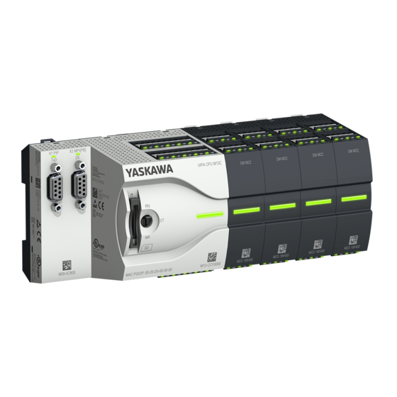
VIPA System MICRO Hardware description Structure > System MICRO CPU M13C 3.2 Structure 3.2.1 System MICRO CPU M13C CPU M13-CCF0000 Slot for external storage media (lockable) Operating mode switch CPU X3: Ethernet PG/OP channel X4: Ethernet PG/OP channel X2: Connector DO +0.0 ... DO +0.7 X1: Connector DI +0.0 ... -
Page 39: Interfaces
VIPA System MICRO Hardware description Structure > Interfaces 3.2.2 Interfaces HB400 | CPU | M13-CCF0000 | en | 18-50... - Page 40 VIPA System MICRO Hardware description Structure > Interfaces X1: DI byte 0 Function Type Description green DI 0.7 Digital input DI 7 / Counter 2 (B) / Frequency 2 * DI 0.6 Digital input DI 6 / Counter 2 (A) * DI 0.5...
- Page 41 VIPA System MICRO Hardware description Structure > Interfaces Function Type Description green DO 0.7 Digital output DO 7 DO 0.6 Digital output DO 6 DO 0.5 Digital output DO 5 DO 0.4 Digital output DO 4 DO 0.3 Digital output DO 3 / Output channel counter 3 DO 0.2...
- Page 42 VIPA System MICRO Hardware description Structure > Interfaces Function Type Description green reserved reserved DI 1.0 Digital input DI 8 DI 1.1 Digital input DI 9 / Counter 3 (A) * DI 1.2 Digital input DI 10 / Counter 3 (B) / Frequency 3 * DI 1.3...
-
Page 43: Leds
VIPA System MICRO Hardware description Structure > LEDs X6: Electronic power supply The CPU has an integrated power supply. The power supply has to be provided with DC 24V. Via the power supply not only the internal electronic of the CPU is provided with voltage, but also the electronic from the integrated IO components. - Page 44 VIPA System MICRO Hardware description Structure > LEDs X1 DI +0.x Digital input Description green DI +0.0 ... DI +0.7 Digital input I+0.0 ... 0.7 has "1" signal Digital input I+0.0 ... 0.7 has "0" signal X1 3L+ Power supply...
- Page 45 VIPA System MICRO Hardware description Structure > LEDs X6 DO +1.x Digital output Description green DO +1.0 ... DO +1.3 Digital output Q+1.0 ... 1.3 has "1" signal Digital output Q+1.0 ... 1.3 has "0" signal X6 1L+ Power supply...
- Page 46 VIPA System MICRO Hardware description Structure > LEDs 3.2.3.1 Status bar CPU Description Start-up LED yellow blinks with 1Hz: State of the CPU after PowerON LEDs green are blinking with 2Hz: During the start-up (OB 100) the status bar blinks for at least 3s.
-
Page 47: Memory Management
VIPA System MICRO Hardware description Structure > Slot for storage media 3.2.3.2 LEDs Ethernet PG/OP channel X3/X4: LEDs Description Link/Activity Speed green yellow The Ethernet PG/OP channel is physically connected to the Ethernet interface. There is no physical connection. Blinking: Shows Ethernet activity. -
Page 48: Buffering Mechanisms
VIPA System MICRO Hardware description Structure > Operating mode switch 3.2.6 Buffering mechanisms The CPU has a capacitor-based mechanism to buffer the internal clock in case of power failure for max. 30 days. With PowerOFF the content of the RAM is automatically stored in the Flash (NVRAM). -
Page 49: Option: Extension Module Em M09 2X Serial Interface
VIPA System MICRO Hardware description Option: Extension module EM M09 2x serial interface 3.3 Option: Extension module EM M09 2x serial interface EM M09 Please note that the interface X2 MPI(PB) does not provide DC 24V, which is necessary for some programming adapters! -
Page 50: Hb400 | Cpu | M13-Ccf0000 | En
VIPA System MICRO Hardware description Option: Extension module EM M09 2x serial interface X2 MPI(PB) 9pin SubD jack (isolated): The interface supports the following functions, which are switch able: MPI (default / after overall reset) The MPI interface serves for the connection between programming unit and CPU. By means of this the project engineering and programming happens. -
Page 51: Technical Data
VIPA System MICRO Hardware description Technical data > Technical data CPU 3.4 Technical data 3.4.1 Technical data CPU Order no. M13-CCF0000 Type CPU M13C Module ID Technical data power supply Power supply (rated value) DC 24 V Power supply (permitted range) DC 20.4...28.8 V... - Page 52 VIPA System MICRO Hardware description Technical data > Technical data CPU Order no. M13-CCF0000 Number of simultaneously utilizable inputs vertical configu- ration Input characteristic curve IEC 61131-2, type 1 Initial data size 16 Bit Technical data digital outputs Number of outputs...
- Page 53 VIPA System MICRO Hardware description Technical data > Technical data CPU Order no. M13-CCF0000 Output data size 12 Bit Technical data analog inputs Number of inputs Cable length, shielded 200 m Rated load voltage Reverse polarity protection of rated load voltage...
- Page 54 VIPA System MICRO Hardware description Technical data > Technical data CPU Order no. M13-CCF0000 Basic error limit thermoresistor ranges Basic error limit thermoresistor ranges with SFU Destruction limit resistance thermometer inputs Thermocouple inputs Thermocouple ranges Operational limit of thermocouple ranges...
- Page 55 VIPA System MICRO Hardware description Technical data > Technical data CPU Order no. M13-CCF0000 Max. inductive load (current range) Typ. open circuit voltage current output Output current ranges Operational limit of current ranges Radical error limit current ranges with SFU...
- Page 56 VIPA System MICRO Hardware description Technical data > Technical data CPU Order no. M13-CCF0000 Modules per rack, max. Number of integrated DP master Number of DP master via CP Operable function modules Operable communication modules PtP Operable communication modules LAN...
- Page 57 VIPA System MICRO Hardware description Technical data > Technical data CPU Order no. M13-CCF0000 S7 counter remanence adjustable 0 up to 256 S7 counter remanence adjustable C0 .. C7 Number of S7 times S7 times remanence adjustable 0 up to 256...
- Page 58 VIPA System MICRO Hardware description Technical data > Technical data CPU Order no. M13-CCF0000 Integrated digital outputs Analog inputs Analog outputs Analog inputs, central Analog outputs, central Integrated analog inputs Integrated analog outputs Communication functions PG/OP channel ü Global data communication ü...
- Page 59 VIPA System MICRO Hardware description Technical data > Technical data CPU Order no. M13-CCF0000 24V DC Power supply Type Type of interface RS485 isolated Connector Sub-D, 9-pin, female Electrically isolated ü ü MP²I (MPI/RS232) DP master DP slave optional Point-to-point interface 5V DC Power supply max.
- Page 60 VIPA System MICRO Hardware description Technical data > Technical data CPU Order no. M13-CCF0000 Transfer memory inputs, max. 244 Byte Transfer memory outputs, max. 244 Byte Address areas, max. User data per address area, max. 32 Byte Functionality RJ45 interfaces...
- Page 61 VIPA System MICRO Hardware description Technical data > Technical data CPU Order no. M13-CCF0000 RK512 protocol USS master protocol ü Modbus master protocol ü Modbus slave protocol ü Special protocols Properties PROFINET I/O-Controller via PG/OP Realtime Class Conformance Class PROFINET IO...
- Page 62 VIPA System MICRO Hardware description Technical data > Technical data CPU Order no. M13-CCF0000 Management & diagnosis via PG/OP Protocols ICMP LLDP / SNMP Web based diagnosis ü NCM diagnosis Ethernet communication via PG/OP Number of productive connections via PG/OP, max.
- Page 63 VIPA System MICRO Hardware description Technical data > Technical data CPU Order no. M13-CCF0000 Dimensions (WxHxD) 72 mm x 88 mm x 71 mm Net weight 230 g Weight including accessories 230 g Gross weight 250 g Environmental conditions Operating temperature 0 °C to 60 °C...
-
Page 64: Technical Data Em M09
VIPA System MICRO Hardware description Technical data > Technical data EM M09 3.4.2 Technical data EM M09 Order no. M09-0CB00 Type Micro Extension 2xRS485 Module ID Status information, alarms, diagnostics Status display green LED Interrupts Process alarm Diagnostic interrupt Diagnostic functions... -
Page 65: Deployment Cpu M13-Ccf0000
VIPA System MICRO Deployment CPU M13-CCF0000 Start-up behavior Deployment CPU M13-CCF0000 4.1 Assembly Ä Chap. 2 ‘Basics and Information about assembly and cabling mounting’ page 11. 4.2 Start-up behavior Turn on power supply The CPU checks whether a project AUTOLOAD.WLD exists on the memory card. If so, an overall reset is executed and the project is automatically loaded from the memory card. -
Page 66: Addressing
VIPA System MICRO Deployment CPU M13-CCF0000 Addressing > Default address assignment of the I/O part 4.3 Addressing 4.3.1 Overview To provide specific addressing of the installed peripheral modules, certain addresses must be allocated in the CPU. This address mapping is in the CPU as hardware configu- ration. -
Page 67: Option: Addressing Periphery Modules
VIPA System MICRO Deployment CPU M13-CCF0000 Addressing > Option: Addressing periphery modules 4.3.3 Option: Addressing periphery modules The CPU M13-CCF0000 provides an I/O area (address 0 ... 2047) and a process image of the in- and outputs (each address default 0 ... 127). The size of the process image can Ä... -
Page 68: Hardware Configuration - Cpu
VIPA System MICRO Deployment CPU M13-CCF0000 Hardware configuration - CPU 4.4 Hardware configuration - CPU Precondition The configuration of the CPU takes place at the ‘hardware configurator’ of the Sie- mens SIMATIC Manager V 5.5 SP2 and up. The configuration of the System MICRO CPU happens by means of a virtual PROFINET IO device ‘VIPA MICRO PLC’... - Page 69 VIPA System MICRO Deployment CPU M13-CCF0000 Hardware configuration - CPU Use [New] to create a new subnet and assign valid IP address data for your PROFINET system. With firmware version V. 2.4 and up, you can access the Ethernet PG/OP channel via this IP address data. The configuration via an additional CP is no longer required, but still possible.
-
Page 70: Hardware Configuration - System Micro Modules
VIPA System MICRO Deployment CPU M13-CCF0000 Hardware configuration - System MICRO modules 4.5 Hardware configuration - System MICRO modules System MICRO backplane To connect System MICRO modules, the CPU has a backplane bus, which is supplied by the CPU. Here up to 8 System MICRO modules can be connected. -
Page 71: Hardware Configuration - Ethernet Pg/Op Channel
VIPA System MICRO Deployment CPU M13-CCF0000 Hardware configuration - Ethernet PG/OP channel 4.6 Hardware configuration - Ethernet PG/OP channel Overview The CPU has an integrated Ethernet PG/OP channel. This channel allows you to pro- gram and remote control your CPU. -
Page 72: Take Ip Address Parameters In Project
VIPA System MICRO Deployment CPU M13-CCF0000 Hardware configuration - Ethernet PG/OP channel > Take IP address parameters in project Assign IP address param- You get valid IP address parameters from your system administrator. The assignment of eters the IP address data happens online in the Siemens SIMATIC Manager starting with ver- sion V 5.5 &... - Page 73 VIPA System MICRO Deployment CPU M13-CCF0000 Hardware configuration - Ethernet PG/OP channel > Take IP address parameters in project Transfer your project. Ethernet PG/OP channel HB400 | CPU | M13-CCF0000 | en | 18-50...
- Page 74 VIPA System MICRO Deployment CPU M13-CCF0000 Hardware configuration - Ethernet PG/OP channel > Take IP address parameters in project 4.6.1.1.1 Time-of-day synchronization NTP method In the NTP mode (Network Time Protocol) the module sends as client time-of-day queries at regular intervals to all configured NTP servers within the sub net. You can define up to 4 NTP server.
- Page 75 VIPA System MICRO Deployment CPU M13-CCF0000 Hardware configuration - Ethernet PG/OP channel > Take IP address parameters in project The configuration happens according to the following procedure: Open the Siemens hardware configurator and, if not already done, configure the Siemens CPU 314C-2 PN/DP (314-6EH04-0AB0 V3.3).
-
Page 76: Setting Standard Cpu Parameters
VIPA System MICRO Deployment CPU M13-CCF0000 Setting standard CPU parameters > Parameterization via Siemens CPU 4.6.1.2.1 Time-of-day synchronization NTP method In the NTP mode (Network Time Protocol) the module sends as client time-of-day queries at regular intervals to all configured NTP servers within the sub net. You can define up to 4 NTP server. -
Page 77: Parameter Cpu
VIPA System MICRO Deployment CPU M13-CCF0000 Setting standard CPU parameters > Parameter CPU 4.7.2 Parameter CPU Supported parameters The CPU does not evaluate each parameter, which may be set at the hardware configu- ration. The parameters of the following registers are not supported: Synchronous cycle interrupts, communication and web. - Page 78 VIPA System MICRO Deployment CPU M13-CCF0000 Setting standard CPU parameters > Parameter CPU Cycle / Clock memory Update OB1 process image cyclically – This parameter is not relevant. Scan cycle monitoring time – Here the scan cycle monitoring time in milliseconds may be set.
- Page 79 VIPA System MICRO Deployment CPU M13-CCF0000 Setting standard CPU parameters > Parameter CPU Execution – Select how often the interrupts are to be triggered. – Intervals ranging from every minute to yearly are available. The intervals apply to the settings made for start date and time.
-
Page 80: Setting Vipa Specific Cpu Parameters
VIPA System MICRO Deployment CPU M13-CCF0000 Setting VIPA specific CPU parameters Protection Level of protection – Here 1 of 3 protection levels may be set to protect the CPU from unauthorized access. – Protection level 1 (default setting): No password adjustable, no restrictions –... -
Page 81: Project Transfer
VIPA System MICRO Deployment CPU M13-CCF0000 Project transfer > Transfer via Ethernet VIPA specific parameters The following parameters may be accessed by means of the properties dialog of the VIPA CPU. Additional retentive memory – Here enter the number of retentive memory bytes. With 0 the value ‘Retentive memory è... -
Page 82: Transfer Via Memory Card
VIPA System MICRO Deployment CPU M13-CCF0000 Project transfer > Option: Transfer via MPI Set via ‘Options è Set PG/PC Interface’ the access path to "TCP/IP ® Network card ..". Click to ‘PLC è Download’ Download ® the dialog "Select target module" is opened. - Page 83 VIPA System MICRO Deployment CPU M13-CCF0000 Project transfer > Option: Transfer via MPI MPI programming cable The MPI programming cables are available at VIPA in different variants. The cables pro- vide a RS232 res. USB plug for the PC and a bus enabled RS485 plug for the CPU. Due to the RS485 connection you may plug the MPI programming cables directly to an already plugged plug on the RS485 jack.
- Page 84 VIPA System MICRO Deployment CPU M13-CCF0000 Project transfer > Option: Transfer via MPI Set the COM port of the PCs and the transfer rate 38400baud for the MPI program- ming cable. Transfer your project via ‘PLC è Load to module’ via MPI to the CPU and save it with ‘PLC è...
-
Page 85: Accessing The Web Server
VIPA System MICRO Deployment CPU M13-CCF0000 Accessing the web server > Device web page 4.10 Accessing the web server Overview The CPU has a web server integrated. This provides access to: Device web page WebVisu project 4.10.1 Device web page Overview Dynamic web page, which exclusively outputs information. - Page 86 VIPA System MICRO Deployment CPU M13-CCF0000 Accessing the web server > Device web page [Expert View] takes you to the advanced "Expert View". Runtime Information Operation Mode STOP_INTERNAL Mode Mode Switch STOP System Time 29.03.17 08:34:14:486 Date, time Time to change the operating mode...
- Page 87 VIPA System MICRO Deployment CPU M13-CCF0000 Accessing the web server > Device web page PG/OP Network Information Ethernet PG/OP channel Device Name Onboard PG/OP Name IP Address 172.20.139.76 Address information Subnet Mask 255.255.255.0 Gateway Address 172.20.139.76 MAC Address 00:20:D5:02:6C:27 Link Mode X3...
- Page 88 VIPA System MICRO Deployment CPU M13-CCF0000 Accessing the web server > Device web page 4.10.1.1.1 Tab: ‘WebVisu’ Information about the web visualization ( ‘WebVisu’ ) are shown here. The creation of a ‘WebVisu’ project is only possible with the SPEED7 Studio V. 1.7 and up.
-
Page 89: Webvisu Project
VIPA System MICRO Deployment CPU M13-CCF0000 Accessing the web server > WebVisu project Subscribed strings: Number of strings or character chains. – free: Here nothing is shown. – used: Number of strings used. – max.: Here nothing is shown. WebVisu Project: Information on the memory allocation for the WebVisu project. - Page 90 VIPA System MICRO Deployment CPU M13-CCF0000 Accessing the web server > WebVisu project Access happens by the IP address of the Ethernet PG/OP channel and the corre- spondingly configured port or via the device web page You can access your web visualization via a web browser. Web browsers based on Windows CE are currently not supported.
-
Page 91: Operating Modes
VIPA System MICRO Deployment CPU M13-CCF0000 Operating modes > Overview 4.11 Operating modes 4.11.1 Overview The CPU has 4 operating modes: Operating mode STOP Operating mode START-UP (OB 100 - restart / OB 102 - cold start *) Operating mode RUN... - Page 92 VIPA System MICRO Deployment CPU M13-CCF0000 Operating modes > Overview Operating mode HOLD The CPU offers up to 3 breakpoints to be defined for program diagnosis. Setting and deletion of breakpoints happens in your programming environment. As soon as a break- point is reached, you may process your program step by step.
-
Page 93: Function Security
VIPA System MICRO Deployment CPU M13-CCF0000 Operating modes > Function security 4.11.2 Function security The CPUs include security mechanisms like a Watchdog (100ms) and a parameterizable cycle time surveillance (parameterizable min. 1ms) that stop res. execute a RESET at the CPU in case of an error and set it into a defined STOP state. -
Page 94: Overall Reset
VIPA System MICRO Deployment CPU M13-CCF0000 Overall reset > Actions after the overall reset 4.12 Overall reset Overview During the overall reset the entire user memory is erased. Data located in the memory card is not affected. You have 2 options to initiate an overall reset:... - Page 95 VIPA System MICRO Deployment CPU M13-CCF0000 Overall reset > Actions after the overall reset Automatic reload If there is a project S7PROG.WLD on the memory card, after an overall reset the CPU attempts to reload this project from the memory card. Here the yellow LED of the status line flickers .
-
Page 96: Firmware Update
"pb" and differs in a number with 6 digits. In the VIPA System MICRO CPU, you can access the pkb file name from the web page. After PowerON and operating mode switch of the CPU in STOP, the CPU checks if there is a *.pkb file at the memory card. -
Page 97: Reset To Factory Settings
VIPA System MICRO Deployment CPU M13-CCF0000 Reset to factory settings Transfer firmware from memory card into CPU Switch the operating mode switch of your CPU in position STOP. Turn off the power supply. Plug the memory card with the firmware file into the CPU. Please take care of the correct plug-in direction of the memory card. -
Page 98: Deployment Storage Media - Vsd, Vsc
VIPA System MICRO Deployment CPU M13-CCF0000 Deployment storage media - VSD, VSC After the 6. static light release the operating mode switch and tip it downwards to ð To confirm the reset process the yellow LED of the status bar blinks (2Hz) . - Page 99 VIPA System MICRO Deployment CPU M13-CCF0000 Deployment storage media - VSD, VSC VSDs are external storage media based on SD memory cards. VSDs are pre-formatted with the PC format FAT 16 (max. 2GB) and can be accessed via a card reader. After PowerON respectively an overall reset the CPU checks, if there is a VSD with data valid for the CPU.
- Page 100 VIPA System MICRO Deployment CPU M13-CCF0000 Deployment storage media - VSD, VSC Accessing the storage To the following times an access takes place on a storage medium: medium After overall reset The CPU checks if a VSC is inserted. If so, the corresponding optional functions are enabled.
-
Page 101: Extended Know-How Protection
VIPA System MICRO Deployment CPU M13-CCF0000 Extended know-how protection 4.16 Extended know-how protection Overview Please note that this functionality is not supported by the Siemens TIA Portal! Besides the "standard" Know-how protection the CPUs from VIPA provide an "extended" know-how protection that serves a secure block protection for accesses of 3. persons. -
Page 102: Cmd - Auto Commands
VIPA System MICRO Deployment CPU M13-CCF0000 CMD - auto commands 4.17 CMD - auto commands Overview A Command file at a memory card is automatically executed under the following condi- tions: CPU is in STOP and memory card is plugged... - Page 103 VIPA System MICRO Deployment CPU M13-CCF0000 CMD - auto commands Command Description Diagnostics entry WEBVISU_PGOP_DISABLE* Disable WebVisu project via Ethernet PG/OP channel 0xE82D *) After a power cycle or loading a hardware configuration, the settings are retained. With reset to the factory settings or over all reset, the WebVisu project is set to the default value "enabled".
-
Page 104: Control And Monitoring Of Variables With Test Functions
VIPA System MICRO Deployment CPU M13-CCF0000 Control and monitoring of variables with test functions 4.18 Control and monitoring of variables with test functions Overview For troubleshooting purposes and to display the status of certain variables you can access certain test functions via the menu item Debug of the Siemens SIMATIC Man- ager. -
Page 105: Diagnostic Entries
VIPA System MICRO Deployment CPU M13-CCF0000 Diagnostic entries ‘PLC This test function returns the condition of a selected operand (inputs, outputs, flags, data è Monitor/Modify word, counters or timers) at the end of program execution. This information is obtained Variables’... -
Page 106: Deployment I/O Periphery
VIPA System MICRO Deployment I/O periphery Overview Deployment I/O periphery 5.1 Overview Project engineering and On this CPU the connectors for digital respectively analog signal and Technological parametrization functions are combined in a one casing. The project engineering happens in the Siemens SIMATIC Manager as Siemens CPU 314C-2 PN/DP (314-6EH04-0AB0 V3.3). -
Page 107: Address Assignment
VIPA System MICRO Deployment I/O periphery Address assignment 5.2 Address assignment Sub module Input Access Assignment address AI5/AO2 WORD Analog input channel 0 (X6) WORD Analog input channel 1 (X6) Sub module Input Access Description address DI24/DO16 BYTE Digital input I+0.0 ... I+0.7 (X1) BYTE Digital input I+1.0 ... -
Page 108: Analog Input
VIPA System MICRO Deployment I/O periphery Analog input > Analog value representation 5.3 Analog input 5.3.1 Properties 2xUx12Bit (0 ... 10V) fixed. The analog channels of the module are not isolated to the electronic power supply. The analog part has no status indication. -
Page 109: Wiring
VIPA System MICRO Deployment I/O periphery Analog input > Wiring Voltage measurement 0 ... 10V Measuring range Voltage Decimal Range Formulas 0 ... 10V > 11.759V 32767 7FFFh overflow 11.759V 32511 7EFFh overdrive range 27648 6C00h nominal range 13824 3600h... -
Page 110: Parametrization
VIPA System MICRO Deployment I/O periphery Analog input > Parametrization Temporarily not used analog inputs must be connected to the concerning ground. 5.3.4 Parametrization 5.3.4.1 Address assignment Sub module Input Access Assignment address AI5/AO2 WORD Analog input channel 0 (X6) -
Page 111: Digital Input
VIPA System MICRO Deployment I/O periphery Digital input > Wiring 5.4 Digital input 5.4.1 Properties 16xDC 24V Maximum input frequency – 10 inputs: 100kHz – 6 inputs: 1kHz Interrupt functions parameterizable Status indication via LEDs 5.4.2 Wiring X1: DI byte 0... -
Page 112: Parametrization
VIPA System MICRO Deployment I/O periphery Digital input > Parametrization X5: DI byte 1 Function Type Description green reserved reserved DI 1.0 Digital input DI 8 DI 1.1 Digital input DI 9 / Counter 3 (A) * DI 1.2 Digital input DI 10 / Counter 3 (B) / Frequency 3 * DI 1.3... -
Page 113: Status Indication
VIPA System MICRO Deployment I/O periphery Digital input > Status indication 5.4.3.3 Input delay Parameter hardware con- The input delay can be configured per channel in groups of 4. figuration An input delay of 0.1ms is only possible with "fast" inputs, which have a max. input Ä... - Page 114 VIPA System MICRO Deployment I/O periphery Digital input > Status indication DI +x Digital input Description green DI +0.0 DI +0.7 Digital I+0.0 ... 0.7 has "1" signal Digital I+0.0 ... 0.7 has "0" signal DI +1.0 ... DI +1.7 Digital input I+1.0 ...
-
Page 115: Digital Output
VIPA System MICRO Deployment I/O periphery Digital output > Wiring 5.5 Digital output 5.5.1 Properties 12xDC 24V, 0.5A Status indication via LEDs 5.5.2 Wiring X2: DO byte 0 Function Type Description green DO 0.7 Digital output DO 7 DO 0.6 Digital output DO 6 DO 0.5... -
Page 116: Parametrization
VIPA System MICRO Deployment I/O periphery Digital output > Status indication 5.5.3 Parametrization 5.5.3.1 Address assignment Sub module Output Access Description address DI24/DO16 BYTE Digital output Q+0.0 ... Q+0.7 (X2) BYTE Digital output Q+1.0 ... Q+1.3 (X6) 5.5.4 Status indication... - Page 117 VIPA System MICRO Deployment I/O periphery Digital output > Status indication Power supply Description green DC 24V electronic section supply DC 24V electronic section supply not available DC 24V power section supply inputs OK DC 24V power section supply inputs not available...
-
Page 118: Counting
VIPA System MICRO Deployment I/O periphery Counting > Wiring 5.6 Counting 5.6.1 Properties 4 channels Various counting modes – once – continuously – periodically Control by the user program via blocks 5.6.2 Wiring 5.6.2.1 Counter inputs X1: DI byte 0... - Page 119 VIPA System MICRO Deployment I/O periphery Counting > Wiring X5: DI byte 1 Function Type Description green DI 1.1 Counter 3 (A) * DI 1.2 Counter 3 (B) * DI 1.3 Gate 3 * DI 1.7 Latch 3 * *) Max. input frequency 100kHz otherwise 1kHz.
-
Page 120: Proceeding
VIPA System MICRO Deployment I/O periphery Counting > Proceeding 5.6.2.2 Counter outputs X2: DO byte 0 Function Type Description green / DO 0.3 Output channel counter 3 DO 0.2 Output channel counter 2 DO 0.1 Output channel counter 1 DO 0.0... -
Page 121: Parametrization
VIPA System MICRO Deployment I/O periphery Counting > Parametrization Among others the SFB 47 contains a request interface. Hereby you get read and write access to the registers of the appropriate counter. So that a new job may be executed, the previous job must have be finished with JOB_DONE = TRUE. - Page 122 VIPA System MICRO Deployment I/O periphery Counting > Parametrization 5.6.4.2 Interrupt selection Via ‘Basic parameters’ you can reach ‘Select interrupt’ . Here you can define the inter- rupts the CPU will trigger. The following parameters are supported: None: The interrupt function is disabled.
- Page 123 VIPA System MICRO Deployment I/O periphery Counting > Parametrization Operating parameters Description Assignment Comparison value The count value is compared with the comparison value. See also the parameter "Characteristics of the output": No main counting direction – Range of values: -2)
- Page 124 VIPA System MICRO Deployment I/O periphery Counting > Parametrization Output Description Assignment Characteristics of the output The output and the "Comparator" (STS_CMP) status bit No comparison are set, dependent on this parameter. No comparison: The output is used as normal output and STS_CMP remains reset.
- Page 125 VIPA System MICRO Deployment I/O periphery Counting > Parametrization Hardware interrupt Description Assignment Overflow Hardware interrupt overflow disabled enabled: Hardware interrupt on overflow the upper counter limit disabled: no hardware interrupt Underflow Hardware interrupt on underrun disabled enabled: Hardware interrupt on underflow the lower...
-
Page 126: Counter Operating Modes
VIPA System MICRO Deployment I/O periphery Counting > Counter operating modes 5.6.5 Counter operating modes 5.6.5.1 Count continuously In this operating mode the counter counts starting with the load value. When the counter counts forward and reaches the upper count limit and another counting pulse in positive direction arrives, it jumps to the lower count limit and counts from there on. - Page 127 VIPA System MICRO Deployment I/O periphery Counting > Counter operating modes 5.6.5.2 Count once 5.6.5.2.1 No main counting direction The counter counts once starting with load value. It is counted forward or backward. The counter limits are fix set to maximum range.
- Page 128 VIPA System MICRO Deployment I/O periphery Counting > Counter operating modes 5.6.5.2.2 Main counting direction forward The counter counts forward starting with the load value. When the counter reaches the End value -1 in positive direction, it jumps to the load value at the next count pulse and the gate is automatically closed.
- Page 129 VIPA System MICRO Deployment I/O periphery Counting > Counter operating modes 5.6.5.2.3 Main counting direction backward The counter counts backward starting with the load value. When the counter reaches the End value +1 in positive direction, it jumps to the load value at the next count pulse and the gate is automatically closed.
- Page 130 VIPA System MICRO Deployment I/O periphery Counting > Counter operating modes 5.6.5.3 Count periodically 5.6.5.3.1 No main counting direction The counter counts forward or backwards starting with the load value. At over- or underrun at the count limits, the counter jumps to the load value and con- tinues counting.
- Page 131 VIPA System MICRO Deployment I/O periphery Counting > Counter operating modes 5.6.5.3.2 Main counting direction forward The counter counts forward starting with the load value. When the counter reaches the end value -1 in positive direction, it jumps to the load value at the next positive count pulse and continues counting.
- Page 132 VIPA System MICRO Deployment I/O periphery Counting > Counter operating modes 5.6.5.3.3 Main counting direction backward Main counting direction backward The counter counts backward starting with the load value. When the counter reaches the end value +1 in positive direction, it jumps to the load value at the next negative count pulse and continues counting.
-
Page 133: Counter - Additional Functions
VIPA System MICRO Deployment I/O periphery Counting > Counter - Additional functions 5.6.6 Counter - Additional functions 5.6.6.1 Overview Schematic structure The illustration shows how the additional functions influence the counting behavior. The following pages describe these additional functions in detail: 5.6.6.2... - Page 134 VIPA System MICRO Deployment I/O periphery Counting > Counter - Additional functions At interrupt function, the counter starts counting with the last recent counter value after gate restart. Counter 0 ... 2 SW gate Gate function Reaction counter 0 ... 2...
- Page 135 VIPA System MICRO Deployment I/O periphery Counting > Counter - Additional functions 5.6.6.4 Additional functions counter 3 Exclusively counter 3 has the following additional functions: HW gate via Gate 3 Latch function 5.6.6.4.1 HW gate via Gate 3 Starting, stopping and interrupting a count function of counter 3 happens via the internal gate (I gate).
- Page 136 VIPA System MICRO Deployment I/O periphery Counting > Counter - Additional functions 5.6.6.5 Counter output channel Characteristics of the Each counter has an output channel. You pre-define the behavior of the counter output output via the parametrization: no comparison: –...
- Page 137 VIPA System MICRO Deployment I/O periphery Counting > Counter - Additional functions ³ Effect at counter value comparison value Counter value ³ comparison value ® output is set and hysteresis activated Leave hysteresis range ® output is reset Counter value ³ comparison value ® output is set and hysteresis activated Leave hysteresis range, output remains set for counter value ³...
- Page 138 VIPA System MICRO Deployment I/O periphery Counting > Counter - Additional functions Counter value = comparison value ® output is set and hysteresis activated Output is reset for leaving hysteresis range and counter value > comparison value Counter value = comparison value ® output is set and hysteresis activated Counter value = comparison value and hysteresis active ®...
-
Page 139: Diagnostics And Interrupt
VIPA System MICRO Deployment I/O periphery Counting > Diagnostics and interrupt 5.6.7 Diagnostics and interrupt Overview GSDML Edge at an digital interrupt input Via the hardware configuration you can define the following trigger for a hardware inter- rupt that can trigger a diagnostics interrupt:... -
Page 140: Frequency Measurement
VIPA System MICRO Deployment I/O periphery Frequency measurement > Properties 5.7 Frequency measurement 5.7.1 Properties In this operating mode the CPU counts the incoming pulses during a specified inte- gration time and outputs them as frequency value. Integration time 10ms ... 10000ms in steps of 1ms configurable... -
Page 141: Wiring
VIPA System MICRO Deployment I/O periphery Frequency measurement > Wiring 5.7.2 Wiring 5.7.2.1 Frequency measurement inputs Connect the signal to be measured at input B of the corresponding counter. X1: DI byte 0 Function Type Description green DI 0.7 Frequency measurement 2 * DI 0.4... -
Page 142: Proceeding
VIPA System MICRO Deployment I/O periphery Frequency measurement > Parametrization 5.7.3 Proceeding Hardware configuration In the Siemens SIMATIC Manager the following steps should be executed: Perform a hardware configuration for the CPU. Ä Chap. 4.4 ‘Hardware configura- tion - CPU’ page 68 Double-click the counter sub module of the CPU 314C-2 PN/DP (314-6EH04-0AB0 V3.3). - Page 143 VIPA System MICRO Deployment I/O periphery Frequency measurement > Parametrization 5.7.4.2 Interrupt selection Via ‘Basic parameters’ you can reach ‘Select interrupt’ . Here you can define the inter- rupts the CPU will trigger. The following parameters are supported: None: The interrupt function is de-activated.
-
Page 144: Status Indication
VIPA System MICRO Deployment I/O periphery Frequency measurement > Status indication 5.7.5 Status indication Function Type Description green DI 0.7 Digital input DI 7 / Counter 2 (B) / Frequency 2 * DI 0.6 Digital input DI 6 / Counter 2 (A) * DI 0.5... - Page 145 VIPA System MICRO Deployment I/O periphery Frequency measurement > Status indication Power supply Description green DC 24V electronic section supply DC 24V electronic section supply not available DC 24V power section supply inputs OK DC 24V power section supply inputs not available...
-
Page 146: Pulse Width Modulation - Pwm
VIPA System MICRO Deployment I/O periphery Pulse width modulation - PWM > Wiring 5.8 Pulse width modulation - PWM 5.8.1 Properties By presetting of time parameters, the CPU evaluates a pulse sequence with according pulse/pause ratio and outputs it via the according output channel. -
Page 147: Proceeding
VIPA System MICRO Deployment I/O periphery Pulse width modulation - PWM > Parametrization Function Type Description green DO 0.1 PWM 1 DO 0.0 PWM 0 4M: GND for PWM LED (red) is on at short circuit respectively overload DC 24V 4L+: DC 24V power section supply for PWM 5.8.3 Proceeding... - Page 148 VIPA System MICRO Deployment I/O periphery Pulse width modulation - PWM > Parametrization Sub module Output Access Description address Counter DWORD reserved DWORD reserved DWORD reserved DWORD reserved 5.8.4.2 Pulse width modulation Parameter hardware con- Default values and structure of this dialog box depend on the selected ‘Operating mode’ .
-
Page 149: Status Indication
VIPA System MICRO Deployment I/O periphery Pulse width modulation - PWM > Status indication Operating parameters Description Assignment Period With the period you define the length of the output sequence, which consists of pulse duration and pulse pause. Range of values: Time base 1ms: 1 ... - Page 150 VIPA System MICRO Deployment I/O periphery Pulse width modulation - PWM > Status indication Power supply Description green DC 24V electronic section supply DC 24V electronic section supply not available DC 24V power section supply inputs OK DC 24V power section supply inputs not available...
-
Page 151: Pulse Train
VIPA System MICRO Deployment I/O periphery Pulse train > Properties 5.9 Pulse train 5.9.1 Properties By presetting of time parameters, the CPU evaluates a pulse sequence with according pulse/pause ratio and outputs it via the according output channel. The output is as a pulse-direction command (P/D). -
Page 152: Wiring
VIPA System MICRO Deployment I/O periphery Pulse train > Proceeding 5.9.2 Wiring 5.9.2.1 Pulse train outputs X2: DO byte 0 Function Type Description green DO 0.1 Pulse train 1 DO 0.0 Pulse train 0 4M: GND for pulse train LED (red) is on at short circuit respectively overload... -
Page 153: Parametrization
VIPA System MICRO Deployment I/O periphery Pulse train > Parametrization User program The SFB 49 should cyclically be called (e.g. OB 1) for controlling the pulse train output. – The SFB 49 is used for PWM and pulse train output. -
Page 154: Status Indication
VIPA System MICRO Deployment I/O periphery Pulse train > Status indication Parameter overview Operating parameters Description Assignment Output format Here specify the range of values for the output. The CPU Per mil hereby determines the pulse duration: Per mil –... -
Page 155: Diagnostic And Interrupt
VIPA System MICRO Deployment I/O periphery Diagnostic and interrupt > Process interrupt Power supply Description green DC 24V electronic section supply DC 24V electronic section supply not available DC 24V power section supply inputs OK DC 24V power section supply inputs not available... - Page 156 VIPA System MICRO Deployment I/O periphery Diagnostic and interrupt > Process interrupt A process interrupt causes a call of the OB 40. Within the OB 40 you may find the logical basic address of the module that initialized the process interrupt by using the Local word 6.
-
Page 157: Diagnostic Interrupt
VIPA System MICRO Deployment I/O periphery Diagnostic and interrupt > Diagnostic interrupt Local double word 8 of OB 40 at frequency measurement Local byte Bit 7...0 Bit 0: End of measurement channel 0 (end of the integration time) Bit 7 ... 1: 0 (fix) Bit 0: End of measurement channel 1 (end of the integration time) Bit 7 ... - Page 158 VIPA System MICRO Deployment I/O periphery Diagnostic and interrupt > Diagnostic interrupt Example: Diagnostic interrupt pro- Every OB 82 call causes an entry in the diagnostic buffer of the CPU containing error cessing cause and module address. By using the SFC 59 you may read the diagnostic bytes. At de-activated diagnostic interrupt you have access to the last recent diagnostic event.
- Page 159 VIPA System MICRO Deployment I/O periphery Diagnostic and interrupt > Diagnostic interrupt Byte Bit 7...0 Bit 3 ... 0: 0 (fix) Bit 4: set at missing internal power supply – Missing power supply DI or DO Bit 7 ... 5: 0 (fix) Bit 5 ...
- Page 160 VIPA System MICRO Deployment I/O periphery Diagnostic and interrupt > Diagnostic interrupt Diagnostic record set 1 at The record set 1 contains the 4byte of the record set 0 and additionally 12byte module Alarm Inputs specific diagnostic data. The diagnostic bytes have the following assignment: Byte Bit 7...0...
- Page 161 VIPA System MICRO Deployment I/O periphery Diagnostic and interrupt > Diagnostic interrupt Byte Bit 7...0 Diagnostic interrupt due to "process interrupt lost" at... Bit 0: ... input I+1.4 Bit 1: 0 (fix) Bit 2: ... input I+1.5 Bit 3: 0 (fix) Bit 4: ...
- Page 162 VIPA System MICRO Deployment I/O periphery Diagnostic and interrupt > Diagnostic interrupt Byte Bit 7...0 Diagnostic interrupt due to "process interrupt lost" at... Bit 0: Gate counter 3 open (activated) Bit 1: Gate counter 3 closed Bit 2: Over-/underflow/end value counter 3...
-
Page 163: Deployment Pg/Op Communication - Productive
VIPA System MICRO Deployment PG/OP communication - productive Basics - Industrial Ethernet in automation Deployment PG/OP communication - productive 6.1 Basics - Industrial Ethernet in automation Overview The flow of information in a company presents a vast spectrum of requirements that must be met by the communication systems. -
Page 164: Basics - Iso/Osi Reference Model
VIPA System MICRO Deployment PG/OP communication - productive Basics - ISO/OSI reference model 6.2 Basics - ISO/OSI reference model Overview The ISO/OSI reference model is based on a proposal that was developed by the Interna- tional Standards Organization (ISO). This represents the first step towards an interna- tional standard for the different protocols. - Page 165 VIPA System MICRO Deployment PG/OP communication - productive Basics - ISO/OSI reference model Layer 5 - Session layer The session layer is also called the communication control layer. It relieves the communi- cation between service deliverer and the requestor by establishing and holding the con- nection if the transport system has a short time fail out.
-
Page 166: Basics - Terms
VIPA System MICRO Deployment PG/OP communication - productive Basics - Terms 6.3 Basics - Terms Network (LAN) A network res. LAN (Local Area Network) provides a link between different stations that enables them to communicate with each other. Network stations consist of PCs, IPCs, TCP/IP adapters, etc. -
Page 167: Basics - Protocols
VIPA System MICRO Deployment PG/OP communication - productive Basics - Protocols 6.4 Basics - Protocols Overview Protocols define a set of instructions or standards that enable computer to establish com- munication connections and exchange information as error free as possible. A commonly... -
Page 168: Basics - Ip Address And Subnet
VIPA System MICRO Deployment PG/OP communication - productive Basics - IP address and subnet Open communication In the ‘open communication’ the communication takes place via the user program by means of handling blocks. These blocks are also part of the Siemens SIMATIC Manager. - Page 169 VIPA System MICRO Deployment PG/OP communication - productive Basics - IP address and subnet Subnet mask binary all "1" binary all "0" IPv4 address Net-ID Host-ID Subnet mask and IPv4 address Net-ID Subnet-ID new Host-ID Address at first start-up At the first start-up of the CPU, the Ethernet PG/OP channel does not have an IP address.
-
Page 170: Fast Introduction
VIPA System MICRO Deployment PG/OP communication - productive Hardware configuration 6.6 Fast introduction Overview At the first commissioning respectively after an overall reset with PowerON again of the CPU, the Ethernet PG/OP channel has no IP address. This can only be reached by its MAC address. -
Page 171: Configure Siemens S7 Connections
VIPA System MICRO Deployment PG/OP communication - productive Configure Siemens S7 connections 6.8 Configure Siemens S7 connections Overview The project engineering of connections i.e. the "link-up" between stations happens in NetPro from Siemens. NetPro is a graphical user interface for the link-up of stations. A communication connection enables the program controlled communication between two participants at the Industrial Ethernet. - Page 172 VIPA System MICRO Deployment PG/OP communication - productive Configure Siemens S7 connections Work environment of For the project engineering of connections, a thorough knowledge with NetPro from Sie- NetPro mens is required! The following passage only describes the basic usage of NetPro. More detailed information about NetPro is to be found in the according online manual res.
- Page 173 VIPA System MICRO Deployment PG/OP communication - productive Configure Siemens S7 connections Projecting connections For the project engineering of connections, open the connection list by selecting the according CPU. Choose Insert new connection in the context menu: Connection partner (partner station) A dialog window opens where you may choose the connection partner and the connection type.
- Page 174 VIPA System MICRO Deployment PG/OP communication - productive Configure Siemens S7 connections Connection types With this CPU exclusively Siemens S7 connection may be configured with Siemens NetPro. Siemens S7 connection For data transfer with Siemens S7 connections the FB/SFB VIPA handling blocks are necessary;...
- Page 175 VIPA System MICRO Deployment PG/OP communication - productive Configure Siemens S7 connections In the following every relevant parameter of a Siemens S7 connection is described: Local connection end point: Here you may define how the connection is to be established. Since the Siemens SIMATIC Manager can identify the communication options by means of the end points, some options are already preset and may not be changed.
-
Page 176: Configure Open Communication
VIPA System MICRO Deployment PG/OP communication - productive Configure Open Communication Function blocks FB/SFB Label Description FB/SFB 12 BSEND Sending data in blocks: FB/SFB 12 BSEND sends data to a remote partner FB/SFB of the type BRCV (FB/SFB 13). The data area to be transmitted is segmented. Each segment is sent individually to the partner. - Page 177 VIPA System MICRO Deployment PG/OP communication - productive Configure Open Communication The following connection-oriented protocols are supported with FBs for open communica- tion via Industrial Ethernet: TCP/IP native according to RFC 793 (connection types 01h and 11h): – During data transmission, no information about the length or about the start and end of a message is transmitted.
- Page 178 VIPA System MICRO Deployment PG/OP communication - productive Configure Open Communication Hardware configuration: Ä Chap. 4.4 ‘Hardware configuration - CPU’ page 68 Ethernet PG/OP channel Ä Chap. 4.6 ‘Hardware configuration - Ethernet PG/OP channel’ page 71 To specify the Ethernet PG/OP channel, the following values are defined in the UDT 65: local_device_id –...
-
Page 179: Deployment Pg/Op Communication - Profinet
VIPA System MICRO Deployment PG/OP communication - PROFINET Basics PROFINET Deployment PG/OP communication - PROFINET – With firmware version V2.4, there is a PROFINET IO controller avail- able via the Ethernet PG/OP channel. – As soon as you use the PROFINET functionality via the Ethernet... - Page 180 VIPA System MICRO Deployment PG/OP communication - PROFINET Basics PROFINET IRT Communication IRT means Isochronous Real-Time. With the IRT communication the bus cycle begins clock-exactly i.e. with a maximum permissible tolerance and is again synchronized. Thereby the time-controlled and synchronous transfer of data is guaranteed.
-
Page 181: Profinet Installation Guidelines
VIPA System MICRO Deployment PG/OP communication - PROFINET PROFINET installation guidelines More information about installing the GSDML file may be found at the manual of the according engineering tool. Structure and content of the GSDML file are defined by IEC 61158. -
Page 182: Deployment As Profinet Io Controller
VIPA System MICRO Deployment PG/OP communication - PROFINET Deployment as PROFINET IO controller > Steps of configuration Topology Linear – With the linear structure all the communication devices are connected via a linear bus topology. – Here the linear bus topology is realized with switches that are already integrated into the PROFINET device. -
Page 183: Commissioning And Initialization
VIPA System MICRO Deployment PG/OP communication - PROFINET Deployment as PROFINET IO controller > Configuration PROFINET IO controller With the Siemens SIMATIC Manager, the CPU M13-CCF0000 from VIPA is to be configured as CPU 314C-2 PN/DP (314-6EH04-0AB0 V3.3) 7.3.2 Commissioning and initialization Assembly and commis- Install your System MICRO with your CPU. - Page 184 VIPA System MICRO Deployment PG/OP communication - PROFINET Deployment as PROFINET IO controller > Configuration PROFINET IO controller Proceeding Open the properties dialog of the PROFINET IO controller by a double-click at PN- The PROFINET interface of the PROFINET IO controller is parameterized with PN-IO, the port with Port 1.
-
Page 185: Configuration Profinet Io Device
VIPA System MICRO Deployment PG/OP communication - PROFINET Deployment as PROFINET IO controller > Configuration PROFINET IO device Tab: ‘Time-of-day In this area you can configure time-of-day master for time-of-day synchronization in the synchronization’ network. Ä Chap. 4.6.1.1.1 ‘Time-of-day synchronization’ page 74 Tab: ‘Options’... -
Page 186: Deployment As Profinet I-Device
VIPA System MICRO Deployment PG/OP communication - PROFINET Deployment as PROFINET I-Device > Steps of configuration Configure IO devices Now the project engineering of the PROFINET IO controller is finished. Please link up now your IO devices with periphery to your IO controller. -
Page 187: Installing The Gsdml File
VIPA System MICRO Deployment PG/OP communication - PROFINET Deployment as PROFINET I-Device > Installing the GSDML file Range of functions Please regard that the PROFINET IO controller supports only the PROFINET functions, which are described in this manual, even if the Sie-... -
Page 188: Configuration As I-Device
VIPA System MICRO Deployment PG/OP communication - PROFINET Deployment as PROFINET I-Device > Configuration as I-Device Proceeding You can find the GSDML files in the download area of www.vipa.com. Load the file and unzip it on your PC. Start the Siemens SIMATIC Manager and install via ‘Options è... -
Page 189: Configuration In The Higher-Level Io Controller
VIPA System MICRO Deployment PG/OP communication - PROFINET Deployment as PROFINET I-Device > Configuration in the higher-level IO controller Create the transfer areas by dragging them to the ‘slots’ as I/O areas from the hardware catalog. There must be no gaps in the slots. To create the transfer areas,... -
Page 190: Error Behavior And Interrupts
VIPA System MICRO Deployment PG/OP communication - PROFINET Deployment as PROFINET I-Device > Error behavior and interrupts Open the properties dialog by double-clicking ‘PN-I-Device’ and enter at ‘device name’ the previously noted name of the VIPA I-Device. The configured name must match the name of the PROFINET IO controller ‘PN-IO’... - Page 191 VIPA System MICRO Deployment PG/OP communication - PROFINET Deployment as PROFINET I-Device > Error behavior and interrupts ... if the number of configured modules in the IO controller is greater than the number of configured modules in the I-Device: –...
- Page 192 VIPA System MICRO Deployment PG/OP communication - PROFINET Deployment as PROFINET I-Device > Error behavior and interrupts Starting position IO controller in RUN, I-Device in RUN Event Station recovery Reaction An OB 86 (recovery) is called in the IO controller.
-
Page 193: Mrp
VIPA System MICRO Deployment PG/OP communication - PROFINET 7.5 MRP Overview To increase the network availability of an industrial Ethernet network, you can connect a line topology together to a ring topology. To set up a ring topology with media redun- dancy, you have to bring together the two free ends of a linear bus topology in one device. -
Page 194: Topology
VIPA System MICRO Deployment PG/OP communication - PROFINET Topology 7.6 Topology Overview By configuring the topology you specify for the PROFINET IO controller the physical con- nections between the stations in your PROFINET IO system These "neighbourhood rela- tions" are used among others at "Device replacement without exchangeable medium". -
Page 195: Device Replacement Without Exchangeable Medium/Pg
VIPA System MICRO Deployment PG/OP communication - PROFINET Device replacement without exchangeable medium/PG 7.7 Device replacement without exchangeable medium/PG Overview IO devices, which support the PROFINET function Device replacement without exchangeable medium/PG get their device name from the controller with the exchange. -
Page 196: Commissioning And Start-Up Behavior
VIPA System MICRO Deployment PG/OP communication - PROFINET Commissioning and start-up behavior 7.8 Commissioning and start-up behavior Start-up on delivery state In the delivery state the CPU is overall reset. After power ON the PROFINET part has no configuration the PROFINET has no configuration. The PROFINET part is passive and can be found by the device search. -
Page 197: Profinet Diagnostics
VIPA System MICRO Deployment PG/OP communication - PROFINET PROFINET diagnostics > Diagnostics during runtime in the user program 7.9 PROFINET diagnostics 7.9.1 Overview There are the following possibilities to get diagnostics information from your system: Diagnostics with the configuration and engineering tool... - Page 198 VIPA System MICRO Deployment PG/OP communication - PROFINET PROFINET diagnostics > Diagnostics during runtime in the user program More information about the usage of this block may be found in the manual "SPEED7 Operation List" from VIPA. Example OB 1...
-
Page 199: Diagnostics Via Ob Start Information
VIPA System MICRO Deployment PG/OP communication - PROFINET PROFINET diagnostics > Diagnostics status indication via SSLs More information about the diagnostics data may be found in the System SLIO manual HB300_FM_050-1BA00. 7.9.4 Diagnostics via OB start information On an error the faulty system generates a diagnostics message for the CPU. Then the CPU calls the according diagnostics OB. - Page 200 VIPA System MICRO Deployment PG/OP communication - PROFINET PROFINET diagnostics > Diagnostics status indication via SSLs Meaning (bus error) (Bus status) (Maintenance) Ethernet interface parameter are not valid. I-Device is configured and Link mode does not correspond to ‘100 Mbps full duplex’...
-
Page 201: Profinet System Limits
VIPA System MICRO Deployment PG/OP communication - PROFINET PROFINET system limits 7.10 PROFINET system limits Maximum number devices Based on the devices, which have to communicate with the IO controller per ms, you can and configurable connec- determine the maximum number of devices. This also results in the maximum number of tions configurable connections. -
Page 202: Option: Ptp Communication
VIPA System MICRO Option: PtP communication Fast introduction Option: PtP communication 8.1 Fast introduction General For the PtP communication the use of the optionally available extension module EM M09 is required. The extension module provides interface X1: PtP (RS422/485) with fixed pin Ä... -
Page 203: Principle Of The Data Transfer
VIPA System MICRO Option: PtP communication Principle of the data transfer 8.2 Principle of the data transfer RS485 PtP communication The data transfer is handled during runtime by using FC/SFCs. The principle of data transfer is the same for all protocols and is shortly illustrated in the following. -
Page 204: Ptp Communication Via Extension Module Em M09
VIPA System MICRO Option: PtP communication PtP communication via extension module EM M09 8.3 PtP communication via extension module EM M09 X1 PtP (RS422/485) 9pin SubD jack: (isolated) Using the PtP functionality the RS485 interface is allowed to connect via serial point-to- point connection to different source res. - Page 205 VIPA System MICRO Option: PtP communication PtP communication via extension module EM M09 RS485 cabling with PROFIBUS cable X1 PtP interface Periphery – *) For traffic-free data transfer use a terminating resistor of approxi- mately 120 – Never connect the cable shield and the M5V (pin 5) together, due to...
- Page 206 VIPA System MICRO Option: PtP communication PtP communication via extension module EM M09 RS485 cabling with For isolated interfaces you have 5V (P5V) isolated at pin 6 and the corresponding ground defined static voltage (M5V) at pin 5. With this isolated voltage, you can assign defined static voltage levels to levels the signal lines and so ensure a low reflection level.
-
Page 207: Parametrization
VIPA System MICRO Option: PtP communication Parametrization > FC/SFC 216 - SER_CFG - Parametrization PtP RS422 cabling with For isolated interfaces you have 5V (P5V) isolated at pin 6 and the corresponding ground defined static voltage (M5V) at pin 5. With this isolated voltage, you can assign defined static voltage levels to levels the signal lines and so ensure a low reflection level. -
Page 208: Communication
VIPA System MICRO Option: PtP communication Protocols and procedures 8.5 Communication 8.5.1 FC/SFC 217 - SER_SND - Send to PtP This block sends data via the serial interface. The repeated call of the FC/SFC 217 SER_SND delivers a return value for 3964R, USS and Modbus via RETVAL that con- tains, among other things, recent information about the acknowledgement of the partner station. - Page 209 VIPA System MICRO Option: PtP communication Protocols and procedures When data is send from the CPU to a peripheral device, any user data is handed to the FC/SFC 217 (SER_SND) and is transferred with added Start- and End-ID to the communication partner.
- Page 210 VIPA System MICRO Option: PtP communication Protocols and procedures The USS protocol (Universelle serielle Schnittstelle = universal serial interface) is a serial transfer protocol defined by Siemens for the drive and system components. This allows to build-up a serial bus connection between a superordinated master and several slave sys- tems.
- Page 211 VIPA System MICRO Option: PtP communication Protocols and procedures Broadcast with set bit 5 in ADR byte A request can be directed to a certain slave ore be send to all slaves as broadcast mes- sage. For the identification of a broadcast message you have to set bit 5 to 1 in the ADR byte.
-
Page 212: Modbus - Function Codes
VIPA System MICRO Option: PtP communication Modbus - Function codes 8.7 Modbus - Function codes Naming convention Modbus has some naming conventions: Modbus differentiates between bit and word access; bits = "Coils" and words = "Reg- ister". Bit inputs are referred to as "Input-Status" and bit outputs as "Coil-Status". - Page 213 VIPA System MICRO Option: PtP communication Modbus - Function codes Code Command Description Read n bits Read n bits of master output area 0x Read n bits Read n bits of master input area 1x Read n words Read n words of master output area 4x...
- Page 214 VIPA System MICRO Option: PtP communication Modbus - Function codes Command telegram Slave address Function code Address 1. bit Number of bits Check sum CRC/LRC 1byte 1byte 1word 1word 1word Respond telegram Slave address Function code Number of Data 1. byte Data 2.
- Page 215 VIPA System MICRO Option: PtP communication Modbus - Function codes Write 1 word 06h Code 06h: Write 1 word to master output area 4x Command telegram Slave address Function code Address word Value word Check sum CRC/LRC 1byte 1byte 1word...
-
Page 216: Option: Deployment Profibus Communication
VIPA System MICRO Option: Deployment PROFIBUS communication Fast introduction Option: Deployment PROFIBUS communication 9.1 Fast introduction Overview For the PROFIBUS communication the use of the optionally available extension module EM M09 is required. The extension module provides interface X2: MPI(PB) with fixed pin Ä... -
Page 217: Profibus Communication
VIPA System MICRO Option: Deployment PROFIBUS communication PROFIBUS communication 9.2 PROFIBUS communication PROFIBUS DP PROFIBUS is an international standard applicable to an open and serial field bus for building, manufacturing and process automation that can be used to create a low (sensor-/actuator level) or medium (process level) performance network of program- mable logic controllers. -
Page 218: Profibus Communication Via Extension Module Em M09
VIPA System MICRO Option: Deployment PROFIBUS communication PROFIBUS communication via extension module EM M09 9.3 PROFIBUS communication via extension module EM M09 X2 MPI(PB) 9pin SubD jack: (isolated) The interface supports the following functionalities, which are switch able by an hardware... - Page 219 VIPA System MICRO Option: Deployment PROFIBUS communication PROFIBUS communication via extension module EM M09 RS485 interface Periphery Never connect the cable shield and the M5V (pin 5) together, since the interfaces could be destroyed! Status indication X2 MPI(PB) Description Slave is in DE (data exchange).
-
Page 220: Deployment As Profibus Dp Slave
VIPA System MICRO Option: Deployment PROFIBUS communication Deployment as PROFIBUS DP slave 9.4 Deployment as PROFIBUS DP slave Fast introduction In the following the deployment of the PROFIBUS section as "intelligent" DP slave on master system is described, which exclusively may be configured in the Siemens SIMATIC Manager. - Page 221 VIPA System MICRO Option: Deployment PROFIBUS communication Deployment as PROFIBUS DP slave Open the properties dialog of the DP interface of the CPU by means of a double- click at ‘MPI/DP’ . Set Interface: type to "PROFIBUS". Connect to PROFIBUS and preset an address (e.g. 2) and confirm with [OK].
-
Page 222: Profibus Installation Guidelines
VIPA System MICRO Option: Deployment PROFIBUS communication PROFIBUS installation guidelines 9.5 PROFIBUS installation guidelines PROFIBUS in general A PROFIBUS DP network may only be built up in linear structure. PROFIBUS DP consists of minimum one segment with at least one master and one slave. - Page 223 VIPA System MICRO Option: Deployment PROFIBUS communication PROFIBUS installation guidelines The PROFIBUS line has to be terminated with its ripple resistor. Please make sure to terminate the last participants on the bus at both ends by activating the terminating resistor.
- Page 224 VIPA System MICRO Option: Deployment PROFIBUS communication PROFIBUS installation guidelines Wiring [1] 1./last bus participant [2] further participants CAUTION! The terminating resistor is only effective, if the connector is installed at a bus participant and the bus participant is connected to a power supply.
-
Page 225: Configuration With Vipa Speed7 Studio
VIPA System MICRO Configuration with VIPA SPEED7 Studio SPEED7 Studio - Overview Configuration with VIPA SPEED7 Studio 10.1 SPEED7 Studio - Overview SPEED7 Studio - Working In this part the project engineering of the VIPA CPU in the VIPA SPEED7 Studio is environment shown. -
Page 226: Speed7 Studio - Work Environment
VIPA System MICRO Configuration with VIPA SPEED7 Studio SPEED7 Studio - Work environment End SPEED7 Studio Select one of the following options if you want to end the program: Main window: Click on the Close button of the SPEED7 Studio program window. - Page 227 VIPA System MICRO Configuration with VIPA SPEED7 Studio SPEED7 Studio - Work environment (1) Menu bar Most of the commands you need for working with SPEED7 Studio are provided in the menu bar. Further commands can be accessed via the context menus using the right mouse button, e.g.
-
Page 228: Project Tree
VIPA System MICRO Configuration with VIPA SPEED7 Studio SPEED7 Studio - Work environment > Project tree 10.2.1 Project tree (1) Title and author (2) Project (3) Documentation (4) PLC (5) Motion Control (6) PLC program (7) Local components (8) Field periphery (9) HMI In the project tree, you can access commands in order to add or delete objects, e.g. -
Page 229: Catalog
VIPA System MICRO Configuration with VIPA SPEED7 Studio SPEED7 Studio - Work environment > Catalog 10.2.2 Catalog (1) Switching to another view (2) Register (3) Show/hide objects (4) Search (5) Filter (6) Objects (7) Catalog information Devices and components which you want to add to the project can be selected in the cat- alog. - Page 230 VIPA System MICRO Configuration with VIPA SPEED7 Studio SPEED7 Studio - Work environment > Catalog (4) Search You can search for certain objects in the catalog. Enter a search text in the input field. ð Only those objects are displayed in the catalog which contain the search text.
-
Page 231: Speed7 Studio - Hardware Configuration - Cpu
VIPA System MICRO Configuration with VIPA SPEED7 Studio SPEED7 Studio - Hardware configuration - CPU 10.3 SPEED7 Studio - Hardware configuration - CPU Precondition For project engineering a thorough knowledge of the SPEED7 Studio is required! Proceeding Start the SPEED7 Studio. -
Page 232: Speed7 Studio - Hardware Configuration - Ethernet Pg/Op Channel
VIPA System MICRO Configuration with VIPA SPEED7 Studio SPEED7 Studio - Hardware configuration - Ethernet PG/OP channel 10.4 SPEED7 Studio - Hardware configuration - Ethernet PG/OP channel Overview The CPU has an integrated Ethernet PG/OP channel. This channel allows you to pro- gram and remote control your CPU. - Page 233 VIPA System MICRO Configuration with VIPA SPEED7 Studio SPEED7 Studio - Hardware configuration - Ethernet PG/OP channel Click in the Project tree at ‘Devices and networking’ . ð You will get a graphical object view of your CPU. Click at the network ‘PG_OP_Ethernet’ .
-
Page 234: Speed7 Studio - Hardware Configuration - I/O Modules
VIPA System MICRO Configuration with VIPA SPEED7 Studio SPEED7 Studio - Hardware configuration - I/O modules Take IP address parame- If you are not online, you can assign IP address data to your Ethernet PG/OP channel ters in project with following proceeding: Start the SPEED7 Studio with your project. -
Page 235: Deployment I/O Periphery
VIPA System MICRO Configuration with VIPA SPEED7 Studio Deployment I/O periphery > Analog input Parametrization For parametrization double-click in the ‘Device configuration’ on the module you want to parametrize. Then the parameters of the module are shown in a dialog. Here you can make your parameter settings. - Page 236 VIPA System MICRO Configuration with VIPA SPEED7 Studio Deployment I/O periphery > Analog input 10.6.2.2 Parametrization in SPEED7 Studio 10.6.2.2.1 ‘I/O addresses’ Sub module Input address Access Assignment WORD Analog input channel 0 (X4) WORD Analog input channel 1 (X4) 10.6.2.2.2...
-
Page 237: Digital Input
VIPA System MICRO Configuration with VIPA SPEED7 Studio Deployment I/O periphery > Digital output 10.6.3 Digital input 10.6.3.1 Overview 16xDC 24V Sub module ‘DI16/DO12’ Ä Chap. 5.4 ‘Digital input’ page 111 10.6.3.2 Parametrization in SPEED7 Studio 10.6.3.2.1 ‘I/O addresses’ Sub module... -
Page 238: Counter
VIPA System MICRO Configuration with VIPA SPEED7 Studio Deployment I/O periphery > Counter 10.6.5 Counter 10.6.5.1 Overview 4 channels Sub module: ‘Count’ Ä Chap. 5.6 ‘Counting’ page 118 10.6.5.2 Parametrization in SPEED7 Studio 10.6.5.2.1 ‘I/O addresses’ Sub module Input address... - Page 239 VIPA System MICRO Configuration with VIPA SPEED7 Studio Deployment I/O periphery > Counter Parameter overview Operating parameters Description Assignment Main count direction None No restriction of the counting range None Up: Restricts the up-counting range. The counter starts from 0 or load value, counts in positive direction up to the declaration end value -1 and then jumps back to load value at the next positive transducer pulse.
- Page 240 VIPA System MICRO Configuration with VIPA SPEED7 Studio Deployment I/O periphery > Counter Input Description Assignment Signal evaluation Specify the signal of the connected encoder: Pulse/direction Pulse/direction At the input count and direction signal are connected At the input there is an encoder connected with the fol- lowing evaluation: –...
- Page 241 VIPA System MICRO Configuration with VIPA SPEED7 Studio Deployment I/O periphery > Counter Frequency Description Assignment Max. counting fre- Specify the max. frequency for track A/pulse, track B/direction, Latch 60kHz quency and HW gate Frequency shortest permissible count pulse 1kHz 400µs...
-
Page 242: Frequency Measurement
VIPA System MICRO Configuration with VIPA SPEED7 Studio Deployment I/O periphery > Frequency measurement 10.6.6 Frequency measurement 10.6.6.1 Overview 4 channels Sub module ‘Counter’ Ä Chap. 5.7 ‘Frequency measurement’ page 140 10.6.6.2 Parametrization in SPEED7 Studio 10.6.6.2.1 ‘I/O addresses’ Sub module... - Page 243 VIPA System MICRO Configuration with VIPA SPEED7 Studio Deployment I/O periphery > Frequency measurement Integration time Counting pulse SW gate Evaluated frequency Parameter overview Operating parameters Description Assignment Integration time Specify the integration time 100ms Range of values: 10ms ... 10000ms in steps of 1ms max.
-
Page 244: Pulse Width Modulation - Pwm
VIPA System MICRO Configuration with VIPA SPEED7 Studio Deployment I/O periphery > Pulse width modulation - PWM 10.6.7 Pulse width modulation - PWM 10.6.7.1 Overview Channel 0 and 1 are supported Sub module ‘Count’ Control by the user program via SFB 49 Ä... - Page 245 VIPA System MICRO Configuration with VIPA SPEED7 Studio Deployment I/O periphery > Pulse width modulation - PWM Parameter overview Operating parameters Description Assignment Output format Here specify the range of values for the output. The CPU Per mil hereby determines the pulse duration: Per mil –...
-
Page 246: Pulse Train
VIPA System MICRO Configuration with VIPA SPEED7 Studio Deployment I/O periphery > Pulse train 10.6.8 Pulse train 10.6.8.1 Overview 2 channels Sub module ‘Count’ Control by the user program via SFB 49 Ä Chap. 5.9 ‘Pulse train’ page 151 10.6.8.2 Parametrization in SPEED7 Studio 10.6.8.2.1... - Page 247 VIPA System MICRO Configuration with VIPA SPEED7 Studio Deployment I/O periphery > Pulse train Number of pulses Period duration Pulse duration Pulse pause Parameter overview Operating parameters Description Assignment Output format Here specify the range of values for the output. The CPU...
-
Page 248: Deployment Web Visualization
VIPA System MICRO Configuration with VIPA SPEED7 Studio Deployment Web visualization Operating parameters Description Assignment Period With the period you define the length of the output sequence, which consists of pulse duration and pulse pause. Range of values: Time base 1ms: 1 ... 87ms Time base 0.1ms: 0.4 ... -
Page 249: Activate Webvisu Functionality
VIPA System MICRO Configuration with VIPA SPEED7 Studio Deployment Web visualization > WebVisu editor 10.7.1 Activate WebVisu functionality Proceeding For your CPU can process a WebVisu project, you have to activate the WebVisu function- ality. Ä Chap. 4.15 ‘Deploy- Insert a memory card from VIPA (VSD, VSC) into your CPU. - Page 250 VIPA System MICRO Configuration with VIPA SPEED7 Studio Deployment Web visualization > WebVisu editor 10.7.2.1 Working environment (1) Toolbar (2) Editor surface (3) Status bar (4) Catalog (5) Properties window (1) Toolbar The toolbar provides important commands for working with the WebVisu editor.
- Page 251 VIPA System MICRO Configuration with VIPA SPEED7 Studio Deployment Web visualization > WebVisu editor Here click at ‘WebVisu configuration’ ð In this settings window, you can create a WebVisu project for your CPU. To create a WebVisu project, click at [ Add WebVisu ].
-
Page 252: Start-Up Of The Webvisu Project
VIPA System MICRO Configuration with VIPA SPEED7 Studio Deployment Web visualization > Start-up of the WebVisu project Edit WebVisu In the ‘Project tree’ , navigate to ‘WebVisu Project > Images’ and click at ‘Main’ . Select ‘Context menu è Open image’... -
Page 253: Access To The Webvisu
VIPA System MICRO Configuration with VIPA SPEED7 Studio Deployment Web visualization > Status of the WebVisu 10.7.4 Access to the WebVisu Via the web server of the CPU, you have access to the device web page and the Web- Visu, controlled via ports. Access to the WebVisu can be password-protected and encrypted by means of SSL certificates. -
Page 254: Speed7 Studio - Project Transfer
VIPA System MICRO Configuration with VIPA SPEED7 Studio SPEED7 Studio - Project transfer > Transfer via MPI Status Meaning loading webvisu project file Error loading WebVisu project, project file may be damaged deleting webvisu project Failed to delete the WebVisu project... - Page 255 VIPA System MICRO Configuration with VIPA SPEED7 Studio SPEED7 Studio - Project transfer > Transfer via MPI MPI programming cable Activate the terminating resistor via switch MPI network Proceeding transfer via Connect your PC to the MPI jack of your CPU via a MPI programming cable.
-
Page 256: Transfer Via Ethernet
VIPA System MICRO Configuration with VIPA SPEED7 Studio SPEED7 Studio - Project transfer > Transfer via Ethernet Confirm the request that the CPU is to be brought into the state STOP. ð The user program and the hardware configuration are transferred via MPI to the CPU. -
Page 257: Transfer Via Memory Card
VIPA System MICRO Configuration with VIPA SPEED7 Studio SPEED7 Studio - Project transfer > Transfer via memory card With ‘Context menu è Copy RAM to ROM’ you can save your project on a memory card, if one is plugged. 10.8.3... -
Page 258: Configuration With Tia Portal
VIPA System MICRO Configuration with TIA Portal TIA Portal - Work environment > General Configuration with TIA Portal 11.1 TIA Portal - Work environment 11.1.1 General General In this chapter the project engineering of the VIPA CPU in the Siemens TIA Portal is shown. -
Page 259: Work Environment Of The Tia Portal
VIPA System MICRO Configuration with TIA Portal TIA Portal - Hardware configuration - CPU 11.1.2 Work environment of the TIA Portal Basically, the TIA Portal has the following 2 views. With the button on the left below you can switch between these views: Portal view The ‘Portal view’... - Page 260 VIPA System MICRO Configuration with TIA Portal TIA Portal - Hardware configuration - CPU Installation GSDML CPU The installation of the PROFINET IO devices ‘VIPA MICRO PLC’ happens in the hard- for PROFINET ware catalog with the following approach: Go to the service area of www.vipa.com.
- Page 261 VIPA System MICRO Configuration with TIA Portal TIA Portal - Hardware configuration - CPU Device overview: Module Slot Type PLC ... CPU 314C-2PN/DP MPI interface... 2 X1 MPI/DP interface PROFINET inter- 2 X2 PROFINET interface face DI24/DO16 DI24/DO16 AI5/AO2... AI5/AO2 Counter...
- Page 262 VIPA System MICRO Configuration with TIA Portal TIA Portal - Hardware configuration - CPU Select in the Network view the IO device ‘VIPA MICRO PLC’ and switch to the Device overview. ð In the Device overview of the PROFINET IO device ‘VIPA MICRO PLC’ the CPU is already placed at slot 0.
-
Page 263: Tia Portal - Hardware Configuration - Ethernet Pg/Op Channel
VIPA System MICRO Configuration with TIA Portal TIA Portal - Hardware configuration - Ethernet PG/OP channel 11.3 TIA Portal - Hardware configuration - Ethernet PG/OP channel Overview The CPU has an integrated Ethernet PG/OP channel. This channel allows you to pro- gram and remote control your CPU. -
Page 264: Take Ip Address Parameters In Project
VIPA System MICRO Configuration with TIA Portal TIA Portal - Hardware configuration - Ethernet PG/OP channel > Take IP address parameters in project Assign IP address param- You get valid IP address parameters from your system administrator. The assignment of... - Page 265 VIPA System MICRO Configuration with TIA Portal TIA Portal - Hardware configuration - Ethernet PG/OP channel > Take IP address parameters in project 11.3.1.1 Configuration via integrated CPU interface Proceeding From firmware version V. 2.4. this variant for configuration is recommended. The fol-...
- Page 266 VIPA System MICRO Configuration with TIA Portal TIA Portal - Hardware configuration - Ethernet PG/OP channel > Take IP address parameters in project 11.3.1.2 Configuration via additional CP Proceeding This is the conventional variant for configuration and is supported by all firmware ver- sions.
- Page 267 VIPA System MICRO Configuration with TIA Portal TIA Portal - Hardware configuration - Ethernet PG/OP channel > Take IP address parameters in project CP 343-1 CP 343-1 11.3.1.2.1 Time-of-day synchronization NTP method In the NTP mode (Network Time Protocol) the module sends as client time-of-day queries at regular intervals to all configured NTP servers within the sub net.
-
Page 268: Tia Portal - Vipa-Include Library
VIPA System MICRO Configuration with TIA Portal TIA Portal - VIPA-Include library 11.4 TIA Portal - VIPA-Include library Overview The VIPA specific blocks can be found in the "Service" area of www.vipa.com as library download file at Downloads > VIPA LIB. -
Page 269: Tia Portal - Project Transfer
VIPA System MICRO Configuration with TIA Portal TIA Portal - Project transfer > Transfer via memory card 11.5 TIA Portal - Project transfer Overview There are the following possibilities for project transfer into the CPU: Transfer via Ethernet Transfer via memory card Option: Transfer via MPI 11.5.1... -
Page 270: Option: Transfer Via Mpi
VIPA System MICRO Configuration with TIA Portal TIA Portal - Project transfer > Option: Transfer via MPI Copy the wld file at a suited memory card. Plug this into your CPU and start it again. ð The transfer of the application program from the memory card into the CPU takes place depending on the file name after an overall reset or PowerON. - Page 271 VIPA System MICRO Configuration with TIA Portal TIA Portal - Project transfer > Option: Transfer via MPI Ä Chap. 2.4 ‘Mounting’ page 14 Mount the extension module. Switch on the power supply. ð After a short boot time the interface X2 MPI(PB) is ready for MPI communica- tion with the MPI address 2.
-
Page 272: Appendix
VIPA System MICRO Appendix Appendix HB400 | CPU | M13-CCF0000 | en | 18-50... - Page 273 VIPA System MICRO Appendix Content System specific event IDs................274 Integrated blocks.................... 322 SSL partial list....................325 HB400 | CPU | M13-CCF0000 | en | 18-50...
-
Page 274: A System Specific Event Ids
VIPA System MICRO System specific event IDs System specific event IDs Ä Chap. 4.19 ‘Diagnostic entries’ page 105 Event IDs Event ID Description 0x115C Manufacture interrupt for EtherCAT / PROFINET IO OB: OB number ZINFO1: Logical address of the slave station that triggered the interrupt... - Page 275 VIPA System MICRO System specific event IDs Event ID Description 0xE005 Internal error - Please contact the hotline! ZINFO1: Not user relevant ZINFO2: Not user relevant ZINFO3: Not user relevant 0xE007 Configured input/output bytes do not fit in the periphery area...
- Page 276 VIPA System MICRO System specific event IDs Event ID Description ZINFO1: Error 4: SSL wrong 5: Sub-SSL wrong 6: Index wrong ZINFO2: SZL-ID ZINFO3: Index 0xE0CC Communication error ZINFO1: Error code 1: Wrong priority 2: Buffer overrun 3: Telegram format error...
- Page 277 VIPA System MICRO System specific event IDs Event ID Description 0xE200 Memory card writing finished (Copy Ram2Rom) OB: Not user relevant PK: Not user relevant 0xE210 Memory card reading finished (reload after memory reset) OB: Not user relevant PK: Not user relevant...
- Page 278 VIPA System MICRO System specific event IDs Event ID Description 70: SFB 97: VDB 98: VSDB 99: VFC 100: VSFC 101: VFB 102: VSFB 111: VOB ZINFO3: Block number 0xE300 Internal flash writing completed (copy Ram2Rom) 0xE310 Internal flash reading completed (recharging after battery failure)
- Page 279 VIPA System MICRO System specific event IDs Event ID Description 23357: 955-C000M00 24576: 955-C000050 35025: 955-C00MC10 36351: FSC-C000S40 36794: FSC-C000M40 37260: 955-C000S40 37833: 955-C000M40 38050: FSC-C00MC10 41460: 955-C000M50 41526: 955-C0PE040 42655: FSC-C00MC00 47852: 955-C00MC00 48709: FSC-C0PE040 50574: 955-C000M70 52366: 955-C000030...
- Page 280 VIPA System MICRO System specific event IDs Event ID Description 4940: FSC-C000S30 5755: 955-C0ME040 6843: FSC-C0NE040 8561: FSC-C000S20 9012: FSC-C000M20 13895: 955-C000060 15618: 955-C000S20 16199: 955-C000M20 17675: FSC-C000S00 18254: FSC-C000M00 20046: FSC-C000040 21053: 955-C000040 22904: 955-C000S00 23357: 955-C000M00 24576: 955-C000050...
- Page 281 VIPA System MICRO System specific event IDs Event ID Description ZINFO2: Number of released axes ZINFO3: Number of configured axes 0xE403 FSC can not be activated in this CPU OB: FCS error code PK: FSC source 0: CPU 1: Card...
- Page 282 VIPA System MICRO System specific event IDs Event ID Description 47852: 955-C00MC00 48709: FSC-C0PE040 50574: 955-C000M70 52366: 955-C000030 53501: FSC-C000030 58048: FSC-C000020 63411: 955-C000M60 65203: 955-C000020 ZINFO2: FSC serial number (high word) ZINFO3: FSC serial number (low word) 0xE404 Feature set deleted due to CRC error...
- Page 283 VIPA System MICRO System specific event IDs Event ID Description 20046: FSC-C000040 21053: 955-C000040 22904: 955-C000S00 23357: 955-C000M00 24576: 955-C000050 35025: 955-C00MC10 36351: FSC-C000S40 36794: FSC-C000M40 37260: 955-C000S40 37833: 955-C000M40 38050: FSC-C00MC10 41460: 955-C000M50 41526: 955-C0PE040 42655: FSC-C00MC00 47852: 955-C00MC00...
- Page 284 VIPA System MICRO System specific event IDs Event ID Description 3903: 955-C000S30 4361: FSC-C000M30 4940: FSC-C000S30 5755: 955-C0ME040 6843: FSC-C0NE040 8561: FSC-C000S20 9012: FSC-C000M20 13895: 955-C000060 15618: 955-C000S20 16199: 955-C000M20 17675: FSC-C000S00 18254: FSC-C000M00 20046: FSC-C000040 21053: 955-C000040 22904: 955-C000S00...
- Page 285 VIPA System MICRO System specific event IDs Event ID Description 56: OB 65: DB 66: SDB 67: FC 68: SFC 69: FB 70: SFB 97: VDB 98: VSDB 99: VFC 100: VSFC 101: VFB 102: VSFB 111: VOB ZINFO3: Block number...
- Page 286 VIPA System MICRO System specific event IDs Event ID Description 0xE503 Inconsistency of code sizes and block sizes in the working memory ZINFO1: Code size ZINFO2: Block size (high word) ZINFO3: Block size (low word) 0xE504 Additional information for CRC error in the working memory...
- Page 287 VIPA System MICRO System specific event IDs Event ID Description ZINFO3: Not user relevant DatID: Not user relevant 0xE705 Too many PROFIBUS slaves configured ZINFO1: Diagnostic address of the PROFIBUS master ZINFO2: Number of configured slaves ZINFO3: Number of admissible slaves...
- Page 288 VIPA System MICRO System specific event IDs Event ID Description ZINFO2: Length of the address range ZINFO3: Size of the process image DatID: Address range 0xE801 CMD - auto command: CMD_START recognized and executed 0xE802 CMD - auto command: CMD_End recognized and executed...
- Page 289 VIPA System MICRO System specific event IDs Event ID Description 0xE80E CMD - auto command: SET_NETWORK recognized and executed 0xE80F Internal error - Please contact the hotline! ZINFO3: Status 0: OK 65153: File create error 65185: File writing error 65186: Odd address for reading...
- Page 290 VIPA System MICRO System specific event IDs Event ID Description 0xE901 Checksum error ZINFO1: Not user relevant ZINFO2: Not user relevant DatID: Not user relevant 0xE902 Internal error - Please contact the hotline! ZINFO1: Not user relevant ZINFO2: Not user relevant...
- Page 291 VIPA System MICRO System specific event IDs Event ID Description ZINFO1: Slot DatID: Not user relevant 0xEA02 SBUS: Internal error (internal plugged sub module not recognized) PK: Not user relevant ZINFO1: Slot ZINFO2: Type identifier target ZINFO3: Type identifier DatID: Not user relevant...
- Page 292 VIPA System MICRO System specific event IDs Event ID Description 7: Not Connected 8: Unknown DatID: Not user relevant 0xEA04 SBUS: Multiple configuration of a periphery address ZINFO1: Periphery address ZINFO2: Slot ZINFO3: Data width 0xEA05 Internal error - Please contact the hotline!
- Page 293 VIPA System MICRO System specific event IDs Event ID Description PK: Not user relevant ZINFO2: HW slot ZINFO3: Interface type DatID: Not user relevant 0xEA1A SBUS: Error in access to SBUS FPGA address table PK: Not user relevant ZINFO2: HW slot...
- Page 294 VIPA System MICRO System specific event IDs Event ID Description DatID: Line 0xEA50 PROFINET IO controller: Error in the configuration OB: Not user relevant PK: Not user relevant ZINFO1: Rack/slot of the controller ZINFO2: Device number ZINFO3: Slot at the device...
- Page 295 VIPA System MICRO System specific event IDs Event ID Description OB: File number PK: Slot of the controller ZINFO1: Firmware major version ZINFO2: Firmware minor version DatID: Line 0xEA62 Internal error - Please contact the hotline! OB: File number. PK: Slot of the controller...
- Page 296 VIPA System MICRO System specific event IDs Event ID Description ZINFO2 - Bit 2: DC parameter invalid ZINFO2 - Bit 3: I device configuration invalid (slot gap) ZINFO2 - Bit 4: MRP configuration invalid (client) 0xEA65 Internal error - Please contact the hotline!
- Page 297 VIPA System MICRO System specific event IDs Event ID Description 1: Dataset error stack 2: Dataset error station ZINFO1: Dataset number ZINFO2: Dataset handle (caller) ZINFO3: Internal error code from PN stack DatID: Device 0xEA69 Internal error - Please contact the hotline!
- Page 298 VIPA System MICRO System specific event IDs Event ID Description ZINFO2: Not user relevant ZINFO3: Not user relevant DatID: Not user relevant 0xEA6C PROFINET IO controller: Incorrect Device-ID OB: Operating mode 0: Configuration in operating condition RUN 1: STOP (update)
- Page 299 VIPA System MICRO System specific event IDs Event ID Description 12: UPDATING 13: DEFECTIVE 14: Error search mode 15: De-energised 253: Process image release in STOP 254: Watchdog 255: Not set PK: Rack/slot ZINFO1: Device ID ZINFO2: Not user relevant...
- Page 300 VIPA System MICRO System specific event IDs Event ID Description OB: Operating mode 0: Configuration in operating condition RUN 1: STOP (update) 2: STOP (memory reset) 3: STOP (auto initialization) 4: STOP (internal) 5: STARTUP (cold start) 6: STARTUP (restart/warm start)
- Page 301 VIPA System MICRO System specific event IDs Event ID Description 129: PNIO 207: RTA error 218: AlarmAck 219: IODConnectRes 220: IODReleaseRes 221: IOD/IOXControlRes 222: IODReadRes 223: IODWriteRes ZINFO2: ErrorDecode 128: PNIORW: Service Read Write 129: PNIO: Other Service or internal e.g. RPC errors 130: Vendor specific ZINFO3: Error code (PN spec.
- Page 302 VIPA System MICRO System specific event IDs Event ID Description 0: INIT 1: STOP 2: READY 3: PAUSE 4: RUN ZINFO1: Filenamehash[0-3] ZINFO2: Filenamehash[4-7] ZINFO3: Line DatID: Current job number 0xEA92 Internal error - Please contact the hotline! OB: Current OB number...
- Page 303 VIPA System MICRO System specific event IDs Event ID Description DatID: Not user relevant 0xEA99 Parameter assignment job could not be executed PK: Not user relevant ZINFO1: File version on MMC/SD (if not 0) ZINFO2: File version of the SBUS module (if not 0)
- Page 304 VIPA System MICRO System specific event IDs Event ID Description 6: STARTUP (restart/warm start) 7: STARTUP (hot restart) 9: RUN 10: HALT 11: COUPLING 12: UPDATING 13: DEFECTIVE 14: Error search mode 15: De-energised 253: Process image release in STOP...
- Page 305 VIPA System MICRO System specific event IDs Event ID Description PK: Not user relevant ZINFO1: Error type 1: SDB parser error 2: Configured address already used 3: Mapping error ZINFO2: Slot (0=cannot be determined) DatID: Not user relevant 0xEB04 SLIO-Bus: Multiple configuration of a periphery address...
- Page 306 VIPA System MICRO System specific event IDs Event ID Description 3: Slot invalid 4: Master configuration invalid 5: Master type invalid 6: Slave diagnostic address invalid 7: Slave address invalid 8: Slave module IO configuration invalid 9: Logical address already in use...
- Page 307 VIPA System MICRO System specific event IDs Event ID Description 0xEC05 EtherCAT: Check the set DC mode of the YASKAWA Sigma 5/7 drive OB: Operating mode 0: Configuration in operating condition RUN 1: STOP (update) 2: STOP (memory reset) 3: STOP (auto initialization)
- Page 308 VIPA System MICRO System specific event IDs Event ID Description 0: Undefined/Unkown 1: Init 2: PreOp 3: Bootstrap 4: SafeOp 8: Op ZINFO1 - Position 8: Previous status 0: Undefined/Unkown 1: Init 2: PreOp 3: Bootstrap 4: SafeOp 8: Op...
- Page 309 VIPA System MICRO System specific event IDs Event ID Description DatID: Input address DatID: Output address 0xEC12 EtherCAT: Recurrence slave ZINFO1 - Position 0: New status 0: Undefined/Unkown 1: Init 2: PreOp 3: Bootstrap 4: SafeOp 8: Op ZINFO1 - Position 8: Previous status...
- Page 310 VIPA System MICRO System specific event IDs Event ID Description 10: HALT 11: COUPLING 12: UPDATING 13: DEFECTIVE 14: Error search mode 15: De-energised 253: Process image release in STOP 254: Watchdog 255: Not set ZINFO2: Diagnostic address of the master...
- Page 311 VIPA System MICRO System specific event IDs Event ID Description DatID: Output address 0xED12 EtherCAT: Breakdown slave ZINFO1 - Position 0: New status 0: Undefined/Unkown 1: Init 2: PreOp 3: Bootstrap 4: SafeOp 8: Op ZINFO1 - Position 8: Previous status...
- Page 312 VIPA System MICRO System specific event IDs Event ID Description 35: Slave station needs to be in SafeOp state 45: Invalid output FMMU configuration 46: Invalid input FMMU configuration 48: Invalid DC Sync configuration 49: Invalid DC Latch configuration 50: PLL error...
- Page 313 VIPA System MICRO System specific event IDs Event ID Description 0xED21 EtherCAT: Incorrect bus status change ZINFO1 - Position 0: New status 0: Undefined/Unkown 1: Init 2: PreOp 3: Bootstrap 4: SafeOp 8: Op ZINFO1 - Position 8: Previous status...
- Page 314 VIPA System MICRO System specific event IDs Event ID Description 3: Bootstrap 4: SafeOp 8: Op ZINFO2: Diagnostic address of the station ZINFO3: AlStatusCode 0: No error 1: Unspecified error 17: Invalid requested status change 18: Unknown requested status 19: Bootstrap not supported...
- Page 315 VIPA System MICRO System specific event IDs Event ID Description DatID: Station not available DatID: Station available DatID: Input address DatID: Output address 0xED23 EtherCAT: Time out while changing the master state to OP, after CPU has changed to RUN...
- Page 316 VIPA System MICRO System specific event IDs Event ID Description ZINFO2: Diagnostic address of the master 0xED31 EtherCAT: Overflow of the interrupt queue ZINFO2: Diagnostic address of the master 0xED40 Bus cycle time infringement occurred ZINFO1: Logical address of the IO system...
- Page 317 VIPA System MICRO System specific event IDs Event ID Description 7: STARTUP (hot restart) 9: RUN 10: HALT 11: COUPLING 12: UPDATING 13: DEFECTIVE 14: Error search mode 15: De-energised 253: Process image release in STOP 254: Watchdog 255: Not set...
- Page 318 VIPA System MICRO System specific event IDs Event ID Description 33: Slave station needs to be in INIT state 34: Slave station needs to be in PreOp state 35: Slave station needs to be in SafeOp state 45: Invalid output FMMU configuration...
- Page 319 VIPA System MICRO System specific event IDs Event ID Description 0xED63 EtherCAT: Diagnostic buffer CP: Error in the response to an INIT command OB: EtherCAT station address (high byte) PK: EtherCAT station address (low byte) ZINFO1: Error type 0: Not defined...
- Page 320 VIPA System MICRO System specific event IDs Event ID Description ZINFO2: Not user relevant ZINFO3: Not user relevant DatID: Not user relevant 0xEE01 Internal error - Please contact the hotline! ZINFO3: SFB number 0xEEEE CPU was completely deleted, since after PowerON the start-up could not be finished...
- Page 321 VIPA System MICRO System specific event IDs Event ID Description 29: The component actively disconnected the system connection to the CPU 31: Inconsistency of the component data base by loading SDB xxxx by the rack component (SDB type 0x3100) 32: Periphery enabled by S7-CPU...
-
Page 322: B Integrated Blocks
VIPA System MICRO Integrated blocks Integrated blocks Name Description OB 1 CYCL_EXC Program Cycle OB 10 TOD_INT0 Time-of-day Interrupt OB 20 DEL_INT0 Time delay interrupt OB 21 DEL_INT1 Time delay interrupt OB 32 CYC_INT2 Cyclic interrupt OB 33 CYC_INT3 Cyclic interrupt... - Page 323 VIPA System MICRO Integrated blocks Name Description SFB 49 PULSE Pulse width modulation SFB 52 RDREC Read record set SFB 53 WRREC Write record set SFB 54 RALRM Receiving an interrupt from a periphery module Name Description SFC 0 SET_CLK...
- Page 324 VIPA System MICRO Integrated blocks Name Description SFC 40 EN_IRT Enabling interrupts SFC 41 DIS_AIRT Delaying interrupts SFC 42 EN_AIRT Enabling delayed interrupts SFC 43 RE_TRIGR Re-trigger the watchdog SFC 44 REPL_VAL Replace value to ACCU1 SFC 46 STOP the CPU...
-
Page 325: Cssl Partial List
VIPA System MICRO SSL partial list SSL partial list More information about this may be found in the manual "SPEED7 Oper- ation List" from VIPA. SSL-ID SSL partial list xy11h Module identification xy12h CPU characteristics xy13h User memory areas xy14h...
Need help?
Do you have a question about the VIPA System MICRO and is the answer not in the manual?
Questions and answers