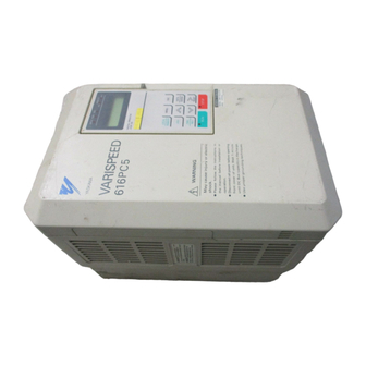
Summary of Contents for YASKAWA VS-616PC5 Series
- Page 1 VS-616PC5/P5 Option Instruction Manual Isolated 4-20mA Output Monitor Card CM-B2/P...
- Page 2 NOTICE Printed November 1996. The information contained within this document is the proprietary property of Yaskawa Electric America, Inc., and may not be copied, reproduced or transmitted to other parties without the expressed written authorization of Yaskawa Electric America, Inc.
-
Page 3: Code Number
INTRODUCTION The Isolated Monitor Card CM-B2/P is mounted on the control board of a VS-616PC5 or P5 inverter, and is used to convert the inverter’s analog monitor signals (0 to 10V) to an isolated configurable sig- nal. This option card can be used on any of the VS-616PC5/P5 Series inverters. When purchasing an option card, please specify the inverter model and code number. -
Page 4: Installation
1. Before attempting to install or use the Isolated Monitor Card CM-B2/P, read these instructions. 2. After unpacking the card, verify that you have received the correct code number and that no dam- age has occurred during shipping. Contact your YASKAWA representative if you should require any assistance. -
Page 5: Front View
Stand Off Posts (4) CM-B2/P 2CN option connector CM-B2/P HDR1 S1 S2 AM AC Connector Refer to Fig. 3 terminal FRONT VIEW SIDE VIEW Fig. 2 Installation of Isolated Monitor Card CM-B2/P JUMPER HDR 1 Configures Output Signal at TB1 HDR1 Note: The three jumpers on the HRD1 are used to configure the... -
Page 6: Interconnection Diagram
INTERCONNECTION DIAGRAM Fig. 4 shows the mounting and interconnection between the inverter and the Isolated Monitor Card CM-B2/P. L1 (R) U (T1) L2 (S) V (T2) L3 (T) W (T3) VS-616/PC5/P5 Current Output 250? E (G) Isolated Monitor Card CM-B2/P Fig. - Page 7 WIRING Refer to the following table for the external function terminals: External Function Terminals TERMINAL BLOCK FUNCTIONS SYMBOL NUMBER Isolated Monitor Output (+) Isolated Monitor Output (-) Wiring Connection Notes: 1. To prevent noise, use shielded wire as specified in Fig. 5. Separate the power circuits (200VAC or greater) and the relay drive circuits from the control wires.
- Page 8 YASKAWA ELECTRIC (SINGAPORE) PTE. LTD. Head Office: CPF Bldg. 79 Robinson Road #13-05, Singapore 0106, SINGAPORE Phone: 221-7530 Telex: (87) 24890 YASKAWA RS Fax: 224-5854 Service Center: 221 Henderson Road, #07-20 Henderson Building Singapore 0315, SINGAPORE Phone: 276-7407 Fax: 276-7406...


Need help?
Do you have a question about the VS-616PC5 Series and is the answer not in the manual?
Questions and answers