YASKAWA iC9200 Series Operating Manual
Hide thumbs
Also See for iC9200 Series:
- Manual (124 pages) ,
- Product manual (138 pages) ,
- Instructions manual (125 pages)

Related Manuals for YASKAWA iC9200 Series


Summary of Contents for YASKAWA iC9200 Series
- Page 1 Series CPU | PMC921xEx | Operating manual HB700 | CPU | PMC921xEx | en | 24-04 IEC 61131 CPU iC921xM-x - Hardware...
- Page 2 YASKAWA Europe GmbH Philipp-Reis-Str. 6 65795 Hattersheim Germany Tel.: +49 6196 569-300 Fax: +49 6196 569-398 Email: info@yaskawa.eu Internet: www.yaskawa.eu.com PMC921xEx_000_CPU iC921xM-x,2,EN - © 2024...
-
Page 3: Table Of Contents
Copyright © YASKAWA Europe GmbH........ - Page 4 General data for iC9200 Series........
- Page 5 Slot for Yaskawa SD card........
- Page 6 Table of contents iC9200 Series 6.3.4 Notifications............... . 179 6.3.5...
-
Page 7: General
Copyright © YASKAWA Europe GmbH All Rights Reserved This document contains proprietary information of Yaskawa and is not to be disclosed or used except in accordance with applicable agreements. This material is protected by copyright laws. It may not be reproduced, distributed, or... -
Page 8: About This Manual
About this manual Technical support Contact your local representative of YASKAWA Europe GmbH if you encounter problems or have questions regarding the product. If such a location is not available, you can reach the YASKAWA customer service via the following contact: YASKAWA Europe GmbH, European Headquarters, Philipp-Reis-Str. - Page 9 General iC9200 Series About this manual Liability Limitation All data and notes in these instructions were prepared with consideration to the statutory standards and regulations, the present state of technology, as well as our many years of knowledge and experience.
-
Page 10: Safety Instructions
Safety instructions Use of this manual This safety manual contains information for the intended use of the iC9200 Series CPUs. Knowledge of regulations and the proper technical implementation of the safety instruc- tions detailed in this manual performed by qualified personnel are prerequisites for safely planning, engineering, programming, installing and starting up the iC9200 Series CPUs as well as for ensuring safety during their operation and maintenance. -
Page 11: Safety Information For Users
If you keep the prescribed environmental conditions the CPU is maintenance-free. ⮫ ‘Approvals, directives, standards’...page 19 Spare parts Please only use original spare parts of Yaskawa. WARNING Incorrect or faulty spare parts can cause damage, malfunction or failure as well as affect security. -
Page 12: Intended Use
General iC9200 Series Responsibility of the user Measurements and altera- When you are conducting measurements on electrostatic sensitive modules you should tions on electrostatic sensi- take the following precautions: tive modules ■ Floating instruments must be discharged before use. ■... -
Page 13: Protective Devices
General iC9200 Series Education of the personnel > Qualification Protective devices Degree of protection The place of installation of the CPU must comply for devices according to IP20. WARNING Serious danger due to improper use Serious dangers for the user and/or damage to property can result from improper or non-intended use and manipulation of the CPU. -
Page 14: Personal Protective Equipment
General iC9200 Series Personal protective equipment Operating personnel The automation system may only be operated by persons, which are trained, instructed and authorized. Troubleshooting, maintenance, cleaning, maintenance and replacement must be performed only by skilled or trained personnel. These persons have to know the instruction manual and have to act accordingly. -
Page 15: Special Hazards
General iC9200 Series Special hazards Wear at special works: Eye to protect eyes from flying parts and liquid splashes. protector 1.10 Special hazards General In the following section the residual risks are listed. Regard the listed safety warnings here and the notes in the whole manual to reduce health hazards and to avoid dangerous situations. -
Page 16: Fire Fighting
General iC9200 Series Electrical safety 1.11 Fire fighting DANGER Risk of death by electric current! Risk of an electrical shock when using a conducting fire fighting medium. Therefore use the following fire fighting medium: ABC powder / CO2 1.12 Electrical safety General The safety CPU is designed according to IEC61131-2 for degree of pollution 2. -
Page 17: Safety Facilities
General iC9200 Series Sign-posting > Signs Direct/indirect contact Ensure protection against direct and indirect contact in accordance with VDE 0100 Part 410 (IEC 60364-4-41) for all components connected to the system. In the event of a fault, parasitic voltages must not occur (single fault security). This also applies to devices and components with dangerous touch voltages that are permanently connected to network and/or diagnostic interfaces of the devices used. -
Page 18: Safety Hints
General iC9200 Series Safety hints Electrical voltage In the such marked work space only qualified personnel may work. Unauthorized may not touch the marked equipment. DANGER Danger of life by electrical power! Time for discharge > 1 Minute Stored electrical charge Therefore: Consider discharge time of capacitor and do not touch live parts before. -
Page 19: Approvals, Directives, Standards
General iC9200 Series Approvals, directives, standards 1.17 Approvals, directives, standards Conformity and approval Conformity 2014/30/EU EMC Directive 2006/42/EC Machinery Directive RoHS (EU) 2011/65/EU Restriction of the use of certain hazardous substances UKCA 2016 No. 1091 Electromagnetic Compatibility Regulations 2008 No. 1597... - Page 20 General iC9200 Series Approvals, directives, standards Standard Comment Emitted interference EN 61000-6-4 Class A (Industrial area) Noise immunity EN 61000-6-2 Industrial area zone B EN 61000-4-2 8kV at air discharge (degree of severity 3), 4kV at contact discharge (degree of severity 2),...
-
Page 21: Use In Difficult Operating Conditions
General iC9200 Series Use in difficult operating conditions Requirements to clearance / creep-age current distances and system power supply DIN EN 61131-2 The definition of clearance and creep-age current distances takes place in accordance to EN 61131-2. For the safe field bus coupler over-voltage cate- gory 2 and degree of pollution 2 are basis. -
Page 22: Basics And Mounting
Basics and mounting iC9200 Series Safety notes for the user Basics and mounting Safety notes for the user DANGER Safety instructions Observe the following safety instructions! Disregarding these safety regula- tions may result in death, serious personal injury or damage to equipment. -
Page 23: Handling And Transport
Basics and mounting iC9200 Series Safety notes for the user > Handling and transport 2.1.1 Handling and transport Handling of electrostatic NOTICE sensitive modules Electrostatic discharge The CPU contains components that can be damaged or destroyed by electro- static discharge. -
Page 24: System Conception
The iC9200 Series is a modular automation system for assembly on a 35mm mounting rail. Due to the compatibility to the System SLIO from Yaskawa you can adapt this system exactly to your automation tasks by using the System SLIO periphery modules in 2-, 4-, 8- and 16-channel versions. - Page 25 Basics and mounting iC9200 Series System conception > Components Power modules When using System SLIO modules, you must always mount the power module 007-1AB00 - DC 24V 10A, because the CPU does not provide a power section supply due to the system.
- Page 26 Basics and mounting iC9200 Series System conception > Components Terminal module The terminal module serves to carry the electronic module, contains the backplane bus with power supply for the electronic, the DC 24V power section supply and the staircase- shaped terminal for wiring. Additionally the terminal module has a locking system for fixing it at a mounting rail.
- Page 27 Basics and mounting iC9200 Series System conception > Components Terminal block The terminal block provides the electrical interface for the signalling and supplies lines of the module. When mounting the terminal block, it is attached to the bottom of the elec- tronic unit and turned towards the electronic unit until it clicks into place.
-
Page 28: Hardware Revision
There is the possibility to fix the assignment of electronic and terminal module. Here coding pins (order number 000-0AC00) from Yaskawa can be used. The coding pin con- sists of a coding jack and a coding plug. By combining electronic and terminal module with coding pin, the coding jack remains in the electronic module and the coding plug in the terminal module. - Page 29 Basics and mounting iC9200 Series Dimensions 8x periphery module 76.5 12.9 electronic module 12.9 HB700 | CPU | PMC921xEx | en | 24-04...
-
Page 30: Mounting
Basics and mounting iC9200 Series Mounting 16x periphery module 76.5 12.9 Mounting WARNING Unintentional machine start-up − Do not mount or dismount when the power is on! − Disconnect the CPU from the power supply before mounting or dis- mounting and secure the power supply against being switched on again! −... -
Page 31: Mounting Cpu
Basics and mounting iC9200 Series Mounting > Mounting CPU 2.4.1 Mounting CPU Functional principle There are locking lever at the top side of the CPU. For mounting and demounting these locking lever are to be turned upwards until these engage. Place the CPU at the mounting rail. -
Page 32: Mounting Periphery Modules
Basics and mounting iC9200 Series Mounting > Mounting periphery modules Turn the locking lever upwards, place the CPU at the mounting rail and turn the lever downward. �� If you want to use the CPU without periphery modules, you can wire it now. - Page 33 Basics and mounting iC9200 Series Mounting > Mounting periphery modules Mounting power module 007-1AB00 Before mounting the periphery modules you have to remove the bus cover at the right side of the CPU by pulling it forward. Keep the cover for later mounting.
-
Page 34: Wiring
Basics and mounting iC9200 Series Wiring > Wiring CPU After mounting the whole system, to protect the backplane bus connectors at the last module you have to mount the bus cover, now. If the last module is a clamp module, for adaptation the upper part of the bus cover is to be removed. -
Page 35: Wiring System Slio Periphery
Basics and mounting iC9200 Series Wiring > Wiring System SLIO periphery Insert through the round connection hole of the according contact your prepared wire until it stops, so that it is fixed. �� By pushing the contact spring opens, thus ensuring the necessary contact pres- sure. - Page 36 Basics and mounting iC9200 Series Wiring > Wiring System SLIO periphery 2.5.2.1 Wiring power module Terminal module terminals With the power module, terminals with spring clamp technology are used for wiring. The spring clamp technology allows quick and easy connection of your supply lines. In contrast to screw terminal connections this type of connection is vibration proof.
- Page 37 Basics and mounting iC9200 Series Wiring > Wiring System SLIO periphery Standard wiring SysDC5V DC 24V DC24V DC24V (1) DC 24V supply CPU: DC 5V electronic section supply I/O area (max. 2A) (2) Power module 007-1AB00: DC 24V power section supply (max. 10A)
- Page 38 Danger of injury from electrical shock and damage to the CPU respectively to the modules! Put the iC9200 Series in a safe, powered down state before starting installa- tion, disassembly or wiring of the iC9200 Series modules! With wiring the terminal modules, terminals with spring clamp technology are used for wiring.
- Page 39 Cable shield mounted with shield clamp Shield attachment Each iC9200 Series 8x periphery module has a carrier hole for the shield bus carrier. Push the shield bus carrier, until they engage into the module. With a flat mounting rail for adaptation to a flat mounting rail you may remove the spacer of the shield bus carrier.
- Page 40 CAUTION Danger of injury from electrical shock and damage to the CPU respectively to the modules! Put the iC9200 Series in a safe, powered down state before starting installa- tion, disassembly or wiring of the iC9200 Series modules! ■ The 16x periphery module has a removable terminal block for wiring.
- Page 41 Basics and mounting iC9200 Series Wiring > Wiring System SLIO periphery Data 30V DC Cross section 0.08 ... 1.5mm (AWG 28 ... 16) Stripping length 10mm Wiring procedure Pin number at the connector Opening for screwdriver Connection hole for wire Insert a suited screwdriver at an angel into the square opening as shown.
- Page 42 Basics and mounting iC9200 Series Wiring > Wiring System SLIO periphery Power module 007-1AB00 SysDC5V DC 24V DC 24V DC24V DC24V DC24V DC24V (1) DC 24V supply CPU: DC 5V electronic section supply I/O area (max. 2A) (2) Power module 007-1AB00: DC 24V power section supply (max.
-
Page 43: Demounting
Basics and mounting iC9200 Series Demounting > Demounting CPU The electronic power section supply is internally protected against higher voltage by fuse. The fuse is within the power module. If the fuse releases, its electronic module must be exchanged! ■... - Page 44 Basics and mounting iC9200 Series Demounting > Demounting CPU Remove the connector of the power supply of the CPU. By pressing the release button as shown, the connector is released and can be removed. For mounting reasons you have to remove the electronic module of the power module located right beside the CPU.
-
Page 45: Demounting 8X Periphery Modules
Basics and mounting iC9200 Series Demounting > Demounting 8x periphery modules Reconnect the connector of the power supply. Now you can bring your system back into operation. 2.6.2 Demounting 8x periphery modules Proceeding Exchange of an electronic Power-off your system. - Page 46 Basics and mounting iC9200 Series Demounting > Demounting 8x periphery modules Pull the module. For mounting turn the locking lever of the module to be mounted upwards. To mount the module put it to the gap between the both modules and push it, guided by the stripes at both sides, to the mounting rail.
-
Page 47: Demounting 16X Periphery Modules
Basics and mounting iC9200 Series Demounting > Demounting 16x periphery modules To mount the module group put it to the gap between the both modules and push it, guided by the stripes at both sides, to the mounting rail. Turn all the locking lever downward, again. - Page 48 Basics and mounting iC9200 Series Demounting > Demounting 16x periphery modules In contrast to 8x periphery modules, you can directly demount and mount 16x periphery modules. Turn the locking lever of the module to be exchanged upwards. Pull the module.
-
Page 49: Device Replacement And Repair
Basics and mounting iC9200 Series Device replacement and repair > Device replacement In contrast to 8x periphery modules, you can directly demount and mount 16x periphery modules. Turn all the locking lever of the module group to be exchanged upwards. -
Page 50: Device Repairs And Defects
■ Always contact your national representative of Yaskawa before returning the product. ■ Return defective devices to the national representative of Yaskawa for repair or to obtain a replacement device. ■ If possible, use the original packaging when returning the product. -
Page 51: Industrial Security And Installation Guidelines
Basics and mounting iC9200 Series Industrial security and installation guidelines > Industrial security in information technology Industrial security and installation guidelines 2.8.1 Industrial security in information technology Latest version This chapter can also be found as a guide ‘Industrial IT Security’ in the ‘Download Center’... - Page 52 Basics and mounting iC9200 Series Industrial security and installation guidelines > Industrial security in information technology 2.8.1.1 Protection of hardware and applications ■ Precautions Do not integrate any components or systems into public networks. – Use VPN "Virtual Private Networks" for use in public networks. This allows you to control and filter the data traffic accordingly.
-
Page 53: Installation Guidelines
Basics and mounting iC9200 Series Industrial security and installation guidelines > Installation guidelines 2.8.1.2 Protection of PC-based software Precautions Since PC-based software is used for programming, configuration and monitoring, it can also be used to manipulate entire systems or individual components. Particular caution is required here! ■... - Page 54 Basics and mounting iC9200 Series Industrial security and installation guidelines > Installation guidelines Possible interference Electromagnetic interferences may interfere your control via different ways: causes ■ Electromagnetic fields (RF coupling) ■ Magnetic fields with power frequency ■ Bus system ■...
- Page 55 Basics and mounting iC9200 Series Industrial security and installation guidelines > Installation guidelines Isolation of conductors Electrical, magnetically and electromagnetic interference fields are weakened by means of an isolation, one talks of absorption. Via the isolation rail, that is connected conductive with the rack, interference currents are shunt via cable isolation to the ground.
-
Page 56: General Data For Ic9200 Series
Basics and mounting iC9200 Series General data for iC9200 Series General data for iC9200 Series Conformity and approval Conformity 2014/30/EU EMC directive Approval UL 61010-2-201 UL is in preparation Others RoHS 2011/65/EU Directive on the restriction of the use of certain haz-... -
Page 57: Use In Difficult Operating Conditions
Basics and mounting iC9200 Series General data for iC9200 Series > Use in difficult operating conditions Standard Comment Emitted interference EN 61000-6-4 Class A (Industrial area) Noise immunity EN 61000-6-2 Industrial area Zone B EN 61000-4-2 8kV at air discharge (degree of severity 3),... -
Page 58: Hardware Description
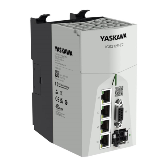
Hardware description iC9200 Series Properties Hardware description Properties ■ Programmable in IEC 61131 via Yaskawa iCube Engineer. iC9212M-EC - PMC9212E0 ■ Slot for external Yaskawa SD card. iC9216M-EC - PMC9216E0 ■ Status LEDs for operating state and diagnostics. iC9212M-FSoE - PMC9212ES ■... -
Page 59: Structure
X3: Ethernet port (internally switched with X4) X4: Ethernet port (internally switched with X3) Password and serial number Slot for Yaskawa SD card SliceBus for System SLIO modules MAC1: MAC address for X3/X4, MAC2: MAC address for X1/X2 QR code... -
Page 60: Interfaces
Hardware description iC9200 Series Structure > Interfaces 3.2.2 Interfaces X1/X2 X3/X4 + DC 24V + DC24V TX1+ TX2+ TX1- TX2- n.c. VBUS VBUS n.c. n.c. n.c. n.c. n.c. VBUS VBUS RX2- RX1- RX2+ RX1+ X1: EtherCAT port 8pin RJ45 jack:... - Page 61 Hardware description iC9200 Series Structure > Interfaces X3/X4: Ethernet port 8pin RJ45 jack: Signal Description Bidirectional pair A + (send data +) Bidirectional pair A - (send data -) Bidirectional pair B + (receive data +) Bidirectional pair C +...
- Page 62 Hardware description iC9200 Series Structure > Interfaces X6: Power supply 2-pin connector: Pos. Signal Description DC 24V Plus DC 24V power supply, bridged in the plug. Ground DC 24V power supply, bridged in the plug. LED indication for power supply.
-
Page 63: Memory
⮫ ‘Memory management’...page 93 Slot for Yaskawa SD card The CPU has a slot for a Yaskawa SD card. Here you can use a Yaskawa SD card as external memory and transfer the overlay file system of the CPU to the card. - Page 64 Hardware description iC9200 Series Structure > LEDs LED bar 1/2 Color Function LED bar 1 green The CPU is in the RUN state without errors. An error has occurred in the CPU. IO ER An error has occurred on the SliceBus.
- Page 65 Error while copying the kernel. Runtime system was stopped. Perform a power cycle. Yaskawa SD card was not recognized. red 2Hz Yaskawa SD card certificate is faulty or was red 2Hz unauthorized removed during operation. Perform a power cycle. Runtime system is loaded.
- Page 66 Hardware description iC9200 Series Structure > LEDs LEDs CPU Status IO ER PN-C ER PN-D ER IO DIAG Description green Reset to factory settings Request reset to factory settings type 1. yellow The CPU requests a power cycle after resetting...
- Page 67 Hardware description iC9200 Series Structure > LEDs LEDs EtherCAT Status EC RN EC ER Description green ■ The EtherCAT master is in INIT state. ■ The EtherCAT master is not configured. ■ 2.5Hz The EtherCAT master is in the PreOp state.
-
Page 68: Dip Switch
Hardware description iC9200 Series Structure > Operating mode switch Status PN-C ER PN-D ER Description not relevant: X 1) The status depends on the operating mode of the CPU. LEDs RJ45 jacks Color Function green The according RJ45 jack is physically connected to the Ethernet. -
Page 69: Technical Data
Hardware description iC9200 Series Technical data > iC9212M-EC - PMC9212E0 Technical data 3.3.1 iC9212M-EC - PMC9212E0 Order no. PMC9212E0 Type iC9212M-EC Module ID Technical data power supply Power supply (rated value) DC 24 V Power supply (permitted range) DC 20.4...28.8 V Reverse polarity protection ü... - Page 70 Hardware description iC9200 Series Technical data > iC9212M-EC - PMC9212E0 Order no. PMC9212E0 SSH/SFTP ü Synchronization via Ethernet (NTP) ü ü IEC 61131 runtime system Program memory 12 MB Data memory 32 MB Retain memory 512 KB Realtime clock Realtime clock ü...
- Page 71 Hardware description iC9200 Series Technical data > iC9212M-EC - PMC9212E0 Order no. PMC9212E0 EtherCAT Master Number of EtherCAT-slaves Update time 500 µs .. 512 ms EoE support CoE support ü FoE support Distributed Clock support ü Hotconnect Slaves ü Isochronous mode ü...
-
Page 72: Ic9216M-Ec - Pmc9216E0
Hardware description iC9200 Series Technical data > iC9216M-EC - PMC9216E0 Order no. PMC9212E0 Controller ü - Max. number of devices 64@16ms, 32@8ms, 16@4ms, 8@2ms, 4@1ms - Cycle time 1 ms .. 512 ms - System Redundancy ü - Fast Startup ü... - Page 73 Hardware description iC9200 Series Technical data > iC9216M-EC - PMC9216E0 Order no. PMC9216E0 Current consumption (no-load operation) 0.2 A Current consumption (rated value) 1.5 A Inrush current I²t 0.3 A²s Max. current drain at backplane bus Max. current drain load supply...
- Page 74 Hardware description iC9200 Series Technical data > iC9216M-EC - PMC9216E0 Order no. PMC9216E0 Realtime clock ü Accuracy Realtime clock 1 minute deviation per month Buffered time 28 days @ 25°C Execution and Synchronization Manager (ESM) Execution and Synchronization Manager (ESM) ü...
- Page 75 Hardware description iC9200 Series Technical data > iC9216M-EC - PMC9216E0 Order no. PMC9216E0 Isochronous mode ü Functional safety Minimum time Maximum time Program memory safe program Data memory Safety protocol Number of FSoE devices Safety related input data Safety related output data...
-
Page 76: Ic9212M-Fsoe - Pmc9212Es
Hardware description iC9200 Series Technical data > iC9212M-FSoE - PMC9212ES Order no. PMC9216E0 - Device I/O Data 512 Byte / 512 Byte - Cycle time 1 ms .. 512 ms - MRP Client supported ü Housing Material Mounting Profile rail 35 mm... - Page 77 Hardware description iC9200 Series Technical data > iC9212M-FSoE - PMC9212ES Order no. PMC9212ES Triton (ARM A17) CPU cores Frequency 1.26 GHz 2 GB eMMC 8 GB Operating controls LEDs, Three-point switch, DIP-switches Integrated SliceBus supply ü Connectors Serial Com (Sub-D) SliceBus ü...
- Page 78 Hardware description iC9200 Series Technical data > iC9212M-FSoE - PMC9212ES Order no. PMC9212ES SliceBus Amount of process data per module up to 60 bytes Max number of modules Cycle time [ms] 500 µs .. 512 ms OPC UA OPC UA ü...
- Page 79 Hardware description iC9200 Series Technical data > iC9212M-FSoE - PMC9212ES Order no. PMC9212ES Safety related input data 512 Byte Safety related output data 512 Byte Standard input data 128 Byte Standard output data 128 Byte Max. number of FB instances...
-
Page 80: Ic9216M-Fsoe - Pmc9216Es
Hardware description iC9200 Series Technical data > iC9216M-FSoE - PMC9216ES Order no. PMC9212ES Net weight 488 g Weight including accessories 503 g Gross weight 621 g Environmental conditions Operating temperature 0 °C to 60 °C Storage temperature -40 °C to 70 °C... - Page 81 Hardware description iC9200 Series Technical data > iC9216M-FSoE - PMC9216ES Order no. PMC9216ES Serial Com (Sub-D) SliceBus ü Number of RJ45 interfaces 4 Ports External SD card External SD card ü Operating system Operating system Linux with RT Kernel Overlay filesystem on internal eMMC ü...
- Page 82 Hardware description iC9200 Series Technical data > iC9216M-FSoE - PMC9216ES Order no. PMC9216ES Sampling rates 100 ms .. 5 s Encryption suite Basic128Rsa15 ü Encryption suite Basic256 ü Encryption suite Basic256Sha256 ü Encryption suite Aes256Sha256RsaPss ü Encryption suite Aes128Sha256RsaOaep ü...
- Page 83 Hardware description iC9200 Series Technical data > iC9216M-FSoE - PMC9216ES Order no. PMC9216ES Cyclic Motion Update Performance up to 4 axes at 250µs up to 16 axes at 500µs up to 32 axes at 1ms up to 64 axes at 2ms...
- Page 84 Hardware description iC9200 Series Technical data > iC9216M-FSoE - PMC9216ES Order no. PMC9216ES KC certification UKCA certification ChinaRoHS certification HB700 | CPU | PMC921xEx | en | 24-04...
-
Page 85: Deployment Cpu Ic921Xm-Ec
Deployment CPU iC921xM-EC iC9200 Series Safety instructions Deployment CPU iC921xM-EC Safety instructions Deployment safety CPU ⮫ ‘Deployment CPU iC921xM-FSoE’...page 108. WARNING Depending on the application, improper use of the CPU can pose serious risks to the user When handling the CPU, observe all safety instructions listed in this chapter. -
Page 86: Mounting
WBM’...page 174 ■ Every open source software that is used in the product is subject to the respective license conditions, which are not affected by the Yaskawa software license conditions (Software License Terms - SLT) for the product. ■ The licensee can change the respective open source software in accordance with the applicable license terms. -
Page 87: Install Icube Engineer
The software iCube Engineer is required for commissioning the CPU. Download the software iCube Engineer to your PC. You can find this at www.yaskawa.eu.com in the ‘Download center’. Unzip the file in your working directory and start the installation by double-clicking on the exe file. -
Page 88: Create A New Project
Deployment CPU iC921xM-EC iC9200 Series Programming and file system > Create a new project ‘Plant’ area In the ‘Plant’ area, you map all the physical and logical components of your application as a hierarchical tree structure. ■ Editor area Double-clicking on a node in the ‘Plant’ area or on an element in the ‘Components’... -
Page 89: Commissioning
Commissioning > Notes on commissioning On the start bar, click on a project template that corresponds to your firmware version, such as Yaskawa CPU iC921xM-x �� The project template for a blank CPU iC921xM-x opens. Open ‘File �� Save Project As’, assign a meaningful name to your project and close the dialog with [Save]. -
Page 90: Online Access To The Cpu
Deployment CPU iC921xM-EC iC9200 Series Commissioning > Online access to the CPU NOTICE Unauthorized access to the SD card possible Access to the SD card is possible so that data can be read and manipulated. − Please note ⮫ ‘Notes on security’...page 13, especially with regard to access protection for the SD card. - Page 91 Deployment CPU iC921xM-EC iC9200 Series Commissioning > Online access to the CPU Set the interface ‘LAN (X3/X4)’ and click on LAN (X3/X4) �� A connection between iCube Engineer and your CPU is established, by means of the IP address parameters, and the login dialog for authentication is opened.
- Page 92 Deployment CPU iC921xM-EC iC9200 Series Commissioning > Online access to the CPU To access WBM, click in the ‘Cockpit’ editor at LAN (X3/X4) �� The WBM login page opens. Please login with your username and password. Username Password Enter Password Login Enter your login details and click on [Login].
-
Page 93: Memory Management
Deployment CPU iC921xM-EC iC9200 Series Memory management > Internal memory Click on [Apply and Reboot]. �� The settings are accepted, transferred to the CPU and the CPU is automatically restarted for activation. The CPU can now only be reached via the new IP address parameters. - Page 94 CPU may be long term damaged and lead to a device defect. − For applications with high data traffic, use an external Yaskawa SD card as a storage medium for the overlay file system. ■ Non-volatile memory for...
-
Page 95: Slot For Yaskawa Sd Card
4.6.2 Slot for Yaskawa SD card ■ You can only insert a Yaskawa SD card with a valid license file in this slot. Power ■ In the WBM at ‘Security �� SD Card’, you can enable or disable the use of the SD card and call up information about it. - Page 96 CPU without YaskawaSD card. − If the support of the Yaskawa SD card remains enabled and the CPU is operated without a Yaskawa SD card, there is a risk of data theft or data manipulation. − Unauthorized persons may insert a Yaskawa SD card and restart the CPU.
-
Page 97: Mreset And Reset To Factory Settings
Deployment CPU iC921xM-EC iC9200 Series MRESET and reset to factory settings MRESET and reset to factory settings ■ MRESET The CPU is set to the Ready state. ■ The working memory is unloaded, but the user program remains in the overlay file system. -
Page 98: Firmware Update
Deployment CPU iC921xM-EC iC9200 Series Safe Mode Switch off the power supply of the CPU. Set the DIP switch S1 to the default position: S1-1 S1-2 Action After PowerON the CPU starts in Standard Mode - Default setting. Switch on the power supply of the CPU again. -
Page 99: System Variables And Status Information
Deployment CPU iC921xM-EC iC9200 Series System variables and status information > General Switch off the power supply of the CPU. Set the DIP switches S1 under the front flap to the following position: S1-1 S1-2 Action After PowerON the CPU starts in Safe Mode. -
Page 100: System Variables
Deployment CPU iC921xM-EC iC9200 Series System variables and status information > System variables Click the button. �� The ‘Init Value Configuration’ of the selected system variable organized as a data structure is opened below the Data list editor. In ‘Init Value Configuration’ column Element name lists all system variables which are contained in the system variable organized as a data structure. - Page 101 You can use the USER_PARTITION system variable to retrieve various information and memory statistics on the user partition (overlay file system). ■ The partition can be on the external Yaskawa SD card or on the internal memory. ■ The memory is organized in blocks.
- Page 102 Deployment CPU iC921xM-EC iC9200 Series System variables and status information > System variables ■ Task handling In iCube Engineer programs and program parts are treated as tasks. ■ The Execution & Synchronization Manager (ESM) is responsible for coordinating and processing the individual tasks.
- Page 103 Deployment CPU iC921xM-EC iC9200 Series System variables and status information > System variables System variable Type - description NAME STRING - name of the task. EXCEPTION_COUNT USINT - number of exceptions. EXCEPTION_INFOS ESM_EXCEPTION_INFO_ARRAY [1] ... [2] ESM_EXCEPTION_INFO - Information on the exceptions [1 ... 2] TYPE_ID UDINT - ID of the exception.
- Page 104 Deployment CPU iC921xM-EC iC9200 Series System variables and status information > System variables System variable Type - description SB_DIAG_ALARM_ACK_PENDING ULINT - acknowledgement diagnostic status of the modules ■ As soon as a module on the SliceBus requests an acknowl- edgement of the diagnostic alarm, according to the slot position the corresponding bit is set in the 64-bit register.
- Page 105 Deployment CPU iC921xM-EC iC9200 Series System variables and status information > System variables System variable Description EC_SLAVE_STATE ARRAY[0…512] OF BYTE - slave states ■ Returns all states of the EtherCAT slaves connected to the EtherCAT master: – 00h: The state is unknown.
- Page 106 Deployment CPU iC921xM-EC iC9200 Series System variables and status information > System variables System variable Type - description PNIO_FORCE_FAILSAFE BOOL - All PROFINET devices are prompted to set their config- ured substitute values. ■ The system variable can be written/set from the program if required.
- Page 107 Deployment CPU iC921xM-EC iC9200 Series System variables and status information > System variables System variable Type - description PND_S1_INPUTS PND_IO_512 - input process data ■ Memory area for input process data that the PROFINET device receives from the higher-level PROFINET controller.
-
Page 108: Deployment Cpu Ic921Xm-Fsoe
Deployment CPU iC921xM-FSoE iC9200 Series Safety instructions Deployment CPU iC921xM-FSoE Safety instructions WARNING Depending on the application, improper use of the CPU can pose serious risks to the user When handling the CPU, observe all safety instructions listed in this chapter. - Page 109 Deployment CPU iC921xM-FSoE iC9200 Series Safety instructions NOTICE Availability requirement The CPU is not suitable for applications that require increased availability, as operation will be stopped in the event of a fault. NOTICE Property damage due to incorrect use The IP20 (IEC 60529/EN 60529) protection class of the CPU is intended for a clean and dry environment.
-
Page 110: Mounting
WBM’...page 174 ■ Every open source software that is used in the product is subject to the respective license conditions, which are not affected by the Yaskawa software license conditions (Software License Terms - SLT) for the product. ■ The licensee can change the respective open source software in accordance with the applicable license terms. -
Page 111: Install Icube Engineer
The software iCube Engineer is required for commissioning the CPU. Download the software iCube Engineer to your PC. You can find this at www.yaskawa.eu.com in the ‘Download center’. Unzip the file in your working directory and start the installation by double-clicking on the exe file. -
Page 112: Create A New Project
Deployment CPU iC921xM-FSoE iC9200 Series Programming and file system > Create a new project ‘Plant’ area In the ‘Plant’ area, you map all the physical and logical components of your application as a hierarchical tree structure. ■ Editor area Double-clicking on a node in the ‘Plant’ area or on an element in the ‘Components’... -
Page 113: Parametrization Of The Safety Parameters
Deployment CPU iC921xM-FSoE iC9200 Series Programming and file system > Parametrization of the safety parameters Click on ‘New project ...’ �� The iCube Engineer user interface is opens. At ‘Components’ select the corresponding safety CPU and drag&drop it onto the ‘Plant’‘Project’. - Page 114 Deployment CPU iC921xM-FSoE iC9200 Series Programming and file system > Parametrization of the safety parameters If a connected safety component only provides 1-channel safety func- tions, you can use the ‘SF_Antivalent...’ and ‘SF_Equivalent...’ handling blocks to generate a 2-channel signal from two 1-channel signals. The blocks can be found in the ‘SF Library’, which must be installed if neces-...
-
Page 115: Assigning Safety Process Data
Deployment CPU iC921xM-FSoE iC9200 Series Commissioning > Notes on commissioning After requesting the password for the safety area, enter the F address that you have set on your F device at ‘FSoE device address’. Setting the safety parame- At ‘Safety parameters’, you can set the required safety parameters that are provided ters by the F device. - Page 116 Deployment CPU iC921xM-FSoE iC9200 Series Commissioning > Notes on commissioning WARNING Safety function only ensured after validation − The planned safety function of the plant/machine is only ensured after validation. WARNING Organizational or technical measures required for compensation of the CRC...
- Page 117 Deployment CPU iC921xM-FSoE iC9200 Series Commissioning > Notes on commissioning NOTICE Damage due to improper handling − Handle the CPU and components with care! − When installing the CPU and components, ensure that mechanical damage is avoided! NOTICE Startup of the CPU not guaranteed −...
-
Page 118: Online Access To The Cpu
Deployment CPU iC921xM-FSoE iC9200 Series Commissioning > Online access to the CPU 5.5.1.1 Notes on initial commissioning WARNING Safety-related steps The following steps include safety-related activities in the iCube Engineer software and the safety validation of the FSoE system. −... - Page 119 Deployment CPU iC921xM-FSoE iC9200 Series Commissioning > Online access to the CPU Connecting to the CPU Please note that the online search is currently only supported by port X3/X4! Connect port X3 or X4 to the Ethernet interface of your PC. Please note that for commu- nication via iCube Engineer the network card of the PC and the Ethernet interface of the CPU are in the same IP circle.
- Page 120 Deployment CPU iC921xM-FSoE iC9200 Series Commissioning > Online access to the CPU To access WBM, click in the ‘Cockpit’ editor at LAN (X3/X4) �� The WBM login page opens. Please login with your username and password. Username Password Enter Password Login Enter your login details and click on [Login].
-
Page 121: Validation Of The System
Deployment CPU iC921xM-FSoE iC9200 Series Commissioning > Validation of the system Click on [Apply and Reboot]. �� The settings are accepted, transferred to the CPU and the CPU is automatically restarted for activation. The CPU can now only be reached via the new IP address parameters. - Page 122 Deployment CPU iC921xM-FSoE iC9200 Series Commissioning > Validation of the system You will find more information in the online help of iCube Engineer. Online access With online access, a distinction is made between safety-related functionality and standard functionality. Access is controlled by double-clicking on the corresponding node below ‘Plant’.
-
Page 123: Comparison Of The Checksums
Deployment CPU iC921xM-FSoE iC9200 Series Memory management > Internal memory Double-click in the ‘Plant’ area on ‘SafetyPLC’ node. �� The cockpit of the safety PLC is opened. Go online with your Safety CPU via Activate debug mode with �� You now have the opportunity to debug your user program and control variables. - Page 124 CPU may be long term damaged and lead to a device defect. − For applications with high data traffic, use an external Yaskawa SD card as a storage medium for the overlay file system. ■ Non-volatile memory for...
-
Page 125: Slot For Yaskawa Sd Card
5.6.2 Slot for Yaskawa SD card ■ You can only insert a Yaskawa SD card with a valid license file in this slot. Power ■ In the WBM at ‘Security �� SD Card’, you can enable or disable the use of the SD card and call up information about it. - Page 126 The cards are pre-formatted (ext4 format) for use in CPUs of the iC9200 Series. − When formatting again, certain information on the Yaskawa SD card that is required for use in the CPUs of the iC9200 Series will be lost. − Exclude the Yaskawa SD card from being formatted. −...
-
Page 127: Mreset And Reset To Factory Settings
Deployment CPU iC921xM-FSoE iC9200 Series MRESET and reset to factory settings In this position the write protection is disabled - delivery state. In this position, the write protection is enabled and the SD card is protected against unintentional overwriting. MRESET and reset to factory settings ■... -
Page 128: Firmware Update
Deployment CPU iC921xM-FSoE iC9200 Series Firmware update Switch on the power supply of the CPU again. After the start-up of the CPU it performs a reset to factory setting type 1 and shows the following LED behavior: Status IO ER... -
Page 129: Safe Mode
Deployment CPU iC921xM-FSoE iC9200 Series Temperature behavior Safe Mode Start-Up in Safe Mode By means of the DIP switch ‘S1’ beneath the front flap you can start your CPU in Safe Mode. Here the CPU starts with the following behavior: ■... -
Page 130: Fail Safe States
Deployment CPU iC921xM-FSoE iC9200 Series Fail safe states Operating temperature Horizontal hanging or vertical hanging the CPU has the following temperature ranges: ■ Horizontal hanging: 0°C to 60°C ■ Vertikal hanging: 0°C to 55°C Warning limits If the temperature falls below -2°C or exceeds 78°C, a warning message is added to the error stack and the log file of the safety CPU. -
Page 131: Response Times
If your CPU is still in the Hard fail safe state after a power cycle and this does not change even after a reset ⮫ ‘MRESET and reset to factory set- tings’...page 127, please contact the Yaskawa hotline. 5.12 Response times 5.12.1... -
Page 132: There Is An Error
Deployment CPU iC921xM-FSoE iC9200 Series Response times > There is an error 5.12.2 There is an error Possible single errors On error, it is assumed that a watchdog responds and triggers the corresponding error response. Possible causes include errors in the system, incorrect runtime information in the documentation of the standard system or an extension of the runtime beyond the value used in the calculation by changing the configuration of the standard system. -
Page 133: Variable Runtimes For Single Errors
Deployment CPU iC921xM-FSoE iC9200 Series Response times > Variable runtimes for single errors 5.12.3 Variable runtimes for single errors Times to be considered At variable run times of the standard system in addition to an existing error, it is assumed that the values of all the relevant run times are nearby the limit of the monitored times. -
Page 134: Maximum Permitted Watchdog Times
Deployment CPU iC921xM-FSoE iC9200 Series Response times > Cycle monitoring time T safety CPU CL_MAX 5.12.4 Maximum permitted watchdog times Dimensioning The following formula applies for dimensioning TI/TO in the FSoE system: FSoEWD_MAX + TO ≤ T - TI - TO... -
Page 135: Designations
Deployment CPU iC921xM-FSoE iC9200 Series Response times > Designations 5.12.7 Designations Abbreviations sorted by components Component Time Description Where from Sensor Delay time of the sensor Documentation of the sensor. SensorDLY (Sensor DeLaY). Safety SDI Input smoothing time of the... -
Page 136: Sample Application
SM 021 (021-1SD10) System SLIO safety DO SM 022 (022-1SD10) Software Function iCube Engineer iCube Engineer supports the programming and configuration of PLCs of the iC9200 Series generation and their FSoE variants. HB700 | CPU | PMC921xEx | en | 24-04... -
Page 137: Configuration In Icube Engineer
Deployment CPU iC921xM-FSoE iC9200 Series Sample application > Configuration in iCube Engineer F addresses Before installing the following modules, set the corresponding F address using the DIP switch: Module F address decimal Switch setting System SLIO DI local 0000 0000 0001... - Page 138 Deployment CPU iC921xM-FSoE iC9200 Series Sample application > Configuration in iCube Engineer Open iCube Engineer and select the template for your safety CPU. �� Save the project under a suitable project name. Leave the Project path unchanged. �� HB700 | CPU | PMC921xEx | en | 24-04...
- Page 139 Deployment CPU iC921xM-FSoE iC9200 Series Sample application > Configuration in iCube Engineer Click on ‘Safety-related Area’ and enter the safety password. The password "safety" is used in the template. Click [OK]. �� Double-click at ‘Plant’ in your project, on ‘SliceBus’ and add your local SLIO modules by entering a relevant part of the name and clicking on a suggested module.
- Page 140 Deployment CPU iC921xM-FSoE iC9200 Series Sample application > Configuration in iCube Engineer Double-click under ‘Plant’ in your project on ‘EtherCAT’ and add your coupler by entering a relevant part of the name and clicking on a suggested version or the coupler with Enhanced Mode.
- Page 141 Deployment CPU iC921xM-FSoE iC9200 Series Sample application > Configuration in iCube Engineer Please note that, due to the system, the parametrization of the safety module parameters is only possible via the English language view. To switch languages, open the menu ‘Extras �� Options’ and set the language to ‘English’...
- Page 142 Deployment CPU iC921xM-FSoE iC9200 Series Sample application > Configuration in iCube Engineer Enter the safety password and set the following module parameters: ■ Input evaluation: 1 channel ■ Input signal-smoothing: 5ms ■ Test pulse activation: deactivated �� To set the module parameters, double-click on the local safety DO module.
- Page 143 Deployment CPU iC921xM-FSoE iC9200 Series Sample application > Configuration in iCube Engineer Set the following module parameters: ■ Activation Mode: 1 channel ■ Test pule length: 2ms �� Repeat the parametrization for the safety modules on the FSoE EtherCAT coupler.
- Page 144 Deployment CPU iC921xM-FSoE iC9200 Series Sample application > Configuration in iCube Engineer Save your project. Navigate via ‘Components’ to ‘Programming �� Local �� Programmes’ and open ‘S_Main’. �� The program editor for your safety application opens. Enter the safety password and click [OK].
- Page 145 Deployment CPU iC921xM-FSoE iC9200 Series Sample application > Configuration in iCube Engineer Switch to the ‘Variables’ tab and create 8 external variables that will later be assigned to the outputs. Here you can copy the created variables. �� Switch to the ‘Code’ tab, insert the Output variable and assign it to the output variable with even numbering.
- Page 146 Deployment CPU iC921xM-FSoE iC9200 Series Sample application > Configuration in iCube Engineer Double-click on the ‘Safety PLC’ and switch to the ‘Data list’ tab. �� Click in the ‘Process data item’ field of the first output variable and select the safety DO on the ‘SliceBus’...
- Page 147 Deployment CPU iC921xM-FSoE iC9200 Series Sample application > Configuration in iCube Engineer Assign all 8 safety outputs. �� You will receive the following error message: To avoid error messages, create 8 external variables in ‘S_Main’, which you link to the safety inputs.
- Page 148 Deployment CPU iC921xM-FSoE iC9200 Series Sample application > Configuration in iCube Engineer Navigate to the ‘Confirm’ column and enable the checkboxes for all 16 variables. �� In the ‘Plant’ area, double-click the den Controller in your project and switch to ‘Cockpit’...
-
Page 149: Modification
Deployment CPU iC921xM-FSoE iC9200 Series Sample application > Modification Double-click in the ‘Plant’ area, on your ‘Safety PLC’ and switch to the ‘Safety Cockpit’ tab. �� Go online with the symbol. Use the symbol to transfer the project to the safety component of the LAN (X3/X4) safety CPU. - Page 150 Deployment CPU iC921xM-FSoE iC9200 Series Sample application > Modification Open the ‘Code’ tab in ‘S_Main’, drag in an OR and add two more input parameters. �� Use ‘Add input parameter’ to add the input parameters FSOE_MSTR_ADDR_0000x_ACK_REQ and the output FSoE_ACK_REQ.
- Page 151 Deployment CPU iC921xM-FSoE iC9200 Series Sample application > Modification Insert FSoE_ACK_REI and connect it to all FSOE_MSTR_ADDR_0000x_ACK_REI. �� Insert FSoE_PASS_ON and connect it to all FSOE_MSTR_ADDR_0000x_PASS_ON. �� Open the ‘Data list’ of the ‘Safety PLC’ and add the four FSoE variables to the standard component of the safety CPU via ‘Add variable (PLC)’.
- Page 152 Deployment CPU iC921xM-FSoE iC9200 Series Sample application > Modification Select the data direction at ‘I/Q/M’, ‘Q’ for output and ‘I’ for input. �� HB700 | CPU | PMC921xEx | en | 24-04...
- Page 153 Deployment CPU iC921xM-FSoE iC9200 Series Sample application > Modification Nothing should now be highlighted in red in the ‘S_Main’ code. �� Save your project and transfer it. HB700 | CPU | PMC921xEx | en | 24-04...
- Page 154 Deployment CPU iC921xM-FSoE iC9200 Series Sample application > Modification Add all four variables to the ‘Watch window’ via ‘Insert in watch window’. �� Open the ‘Cockpit’ of the Safety PLC ‘Safety cockpit’ and check whether you are online and also switch on the debug mode via ��...
- Page 155 Deployment CPU iC921xM-FSoE iC9200 Series Sample application > Modification Open in ‘Safety PLC’ ‘S_Main:S_Main’. �� Briefly switch the DC 24V power section supply of the IO modules at the backplane bus off and on again. �� The safety DO is passivated.
-
Page 156: Functional Safety - Safety Relevant Parameters
Deployment CPU iC921xM-FSoE iC9200 Series Functional safety - safety relevant parameters To re-integrate, set FSoE_ACK_REI to True in the ‘Watch window’. �� As soon as the re-integration is successful, set FSoE_ACK_REI back to False in the ‘Watch window’. 5.14 Functional safety - safety relevant parameters General This chapter describes characteristics associated to functional safety. - Page 157 Deployment CPU iC921xM-FSoE iC9200 Series Functional safety - safety relevant parameters Safety relevant parameters The values specified here refer exclusively to the safety CPUs specified in this manual. Safety-relevant parameters can always be found in the corresponding manuals of the modules.
-
Page 158: System Variables And Status Information
Deployment CPU iC921xM-FSoE iC9200 Series System variables and status information > General 5.15 System variables and status information 5.15.1 General ■ This chapter describes system variables that are available for the CPU. ■ The CPU has a register set that is used for diagnostics and simple control of the CPU. -
Page 159: System Variables
Deployment CPU iC921xM-FSoE iC9200 Series System variables and status information > System variables In ‘Init Value Configuration’ column Element name lists all system variables which are contained in the system variable organized as a data structure. 5.15.2 System variables ■... - Page 160 You can use the USER_PARTITION system variable to retrieve various information and memory statistics on the user partition (overlay file system). ■ The partition can be on the external Yaskawa SD card or on the internal memory. ■ The memory is organized in blocks.
- Page 161 Deployment CPU iC921xM-FSoE iC9200 Series System variables and status information > System variables ■ Task handling In iCube Engineer programs and program parts are treated as tasks. ■ The Execution & Synchronization Manager (ESM) is responsible for coordinating and processing the individual tasks.
- Page 162 Deployment CPU iC921xM-FSoE iC9200 Series System variables and status information > System variables System variable Type - description NAME STRING - name of the task. EXCEPTION_COUNT USINT - number of exceptions. EXCEPTION_INFOS ESM_EXCEPTION_INFO_ARRAY [1] ... [2] ESM_EXCEPTION_INFO - Information on the exceptions [1 ... 2] TYPE_ID UDINT - ID of the exception.
- Page 163 Deployment CPU iC921xM-FSoE iC9200 Series System variables and status information > System variables System variable Type - description SB_DIAG_ALARM_ACK_PENDING ULINT - acknowledgement diagnostic status of the modules ■ As soon as a module on the SliceBus requests an acknowl- edgement of the diagnostic alarm, according to the slot position the corresponding bit is set in the 64-bit register.
- Page 164 Deployment CPU iC921xM-FSoE iC9200 Series System variables and status information > System variables System variable Description EC_SLAVE_STATE ARRAY[0…512] OF BYTE - slave states ■ Returns all states of the EtherCAT slaves connected to the EtherCAT master: – 00h: The state is unknown.
- Page 165 Deployment CPU iC921xM-FSoE iC9200 Series System variables and status information > System variables System variable Type - description PNIO_FORCE_FAILSAFE BOOL - All PROFINET devices are prompted to set their config- ured substitute values. ■ The system variable can be written/set from the program if required.
-
Page 166: System Variables
Deployment CPU iC921xM-FSoE iC9200 Series System variables and status information > System variables System variable Type - description PND_S1_INPUTS PND_IO_512 - input process data ■ Memory area for input process data that the PROFINET device receives from the higher-level PROFINET controller. - Page 167 Deployment CPU iC921xM-FSoE iC9200 Series System variables and status information > System variables System variable Type - description CH2_EXT_PARAM_REG DWORD - Extended diagnostic parameter register of the safety CPU channel 2 (CH2) (additional error messages for service/sup- port). INFO CYCLE_TIME UDINT - Safety CPU cycle in μs.
- Page 168 Deployment CPU iC921xM-FSoE iC9200 Series System variables and status information > System variables NOTICE The warning threshold for CPU load is 70%, the switch-off threshold is 90%. If the 90% CPU load is exceeded, the safety CPU switches off. ■...
- Page 169 Deployment CPU iC921xM-FSoE iC9200 Series System variables and status information > System variables System variable/elements Type - description BOOL - Execution of the safety application program (RUN). ■ The safety CPU executes the safety application program and is in one of the two RUN states (SAFE-RUN or DEBUG-RUN).
- Page 170 Deployment CPU iC921xM-FSoE iC9200 Series System variables and status information > System variables This bit is set if the safety CPU is in one of the two DEBUG states (DEBUG-RUN or DEBUG-STOP/DEBUG-HALT). This bit is not set in the SAFE-STOP and SAFE- RUN states.
-
Page 171: Fsoe Diagnostic Variables
Deployment CPU iC921xM-FSoE iC9200 Series System variables and status information > FSoE diagnostic variables System variables FDEV_INx These system variables are used for data exchange between the standard and safety and FDEV_OUTx (x = 0 ... components of the safety CPU. - Page 172 Deployment CPU iC921xM-FSoE iC9200 Series System variables and status information > FSoE diagnostic variables Variable name Data direction Passivation enabled on output side: The FSoE master sends fail safe on this FSoE connection. ■ 1: If the variable = 1, the output message of this communication instance is set to FailSafeData. In addition, FSOE_MSTR_ADDR_xxxx_PASS_OUT = 1 is set (input data to fail safe).
- Page 173 Deployment CPU iC921xM-FSoE iC9200 Series System variables and status information > FSoE diagnostic variables Global diagnostic variables Variable name Data direction ACK_REQ_FSOE_MSTR_GLOBAL Acknowledge request At least one FSoE connection waits for an operator acknowledge request, e.g. after a change from fail-safe to process data communication.
-
Page 174: Web-Based Management - Wbm
Web-based management - WBM iC9200 Series Overview and first steps Web-based management - WBM Overview and first steps ■ Accessing WBM The CPU has a web-based management (WBM). In the WBM you can access static and dynamic information and change certain settings. You may access WBM via the Ethernet interfaces of the CPU. - Page 175 Area for information output and input dialogs Shows the current hardware/firmware version and MAC address of the CPU. Access to the Yaskawa software license conditions (Software License Terms - SLT) and the license information for the individual Linux packages. HB700 | CPU | PMC921xEx | en | 24-04...
-
Page 176: Overview
Web-based management - WBM iC9200 Series Overview > Cockpit Overview 6.2.1 General Data Here you will find general details about the CPU, e.g. hardware and firmware versions, order number as well as vendor information. Overview iC92... PMC92... General Data Overview... -
Page 177: Diagnostics
Web-based management - WBM iC9200 Series Diagnostics > EtherCAT ■ : Reset - Resets the CPU to factory settings. Similar to the ‘Restart’ command, the loaded application (code and network configuration) is deleted from the RAM but also from the flash memory (boot project). Additionally, all communication settings are reset to default settings. -
Page 178: Motion Alarms
Web-based management - WBM iC9200 Series Diagnostics > Motion Alarms Diagnostics iC92... PMC92... EtherCAT Information Diagnostics Axis Grid EtherCAT Motion Alarms Notifications Profinet SliceBus SliceBus Modules Configuration Security Administration The following information is shown in tabular form: ■ Station address and Station alias ■... -
Page 179: Notifications
Web-based management - WBM iC9200 Series Diagnostics > Notifications ■ ‘Alarm History’ – The last 100 motion alarms are listed here. – The table includes error code, source, description and more detailed information about the corresponding motion alarm. 6.3.4 Notifications Every user with access rights can view and download message entries here. -
Page 180: Profinet - Optional
Web-based management - WBM iC9200 Series Diagnostics > PROFINET - optional ■ Severity – Here you can limit the message entries based on their severity. – The limitation is based on the following graduation for the minimum severity: Internal à Information à Warning à Error à Critical Error à Fatal Error For example with Internal, all degrees of severity are listed. - Page 181 Web-based management - WBM iC9200 Series Diagnostics > PROFINET - optional Tab: ‘Device List’ Diagnostics iC92... PMC92... Profinet Device Liste Profinet Device List Information Device Name IP Address Active Diagnosstics Details PMC92... 192.168... TRUE 0x002B Diagnostics Axis Grid EtherCAT Motion Alarms...
- Page 182 Web-based management - WBM iC9200 Series Diagnostics > PROFINET - optional Controller level On the PROFINET controller level you will find the following information: ■ Controller designation ■ IP Address - IP address of the controller ■ PROFINET Devices - Number of PROFINET devices iC921...
- Page 183 Web-based management - WBM iC9200 Series Diagnostics > PROFINET - optional 6.3.5.1 PROFINET Diagnostics Code Here you can get the status of a connection with an IO controller (Application Relation - AR) bit-coded. Status AR Description and action recommendation Bit 0 is set when there is no connection.
-
Page 184: Slicebus
Web-based management - WBM iC9200 Series Diagnostics > SliceBus Modules Description and action recommendation Bit 9 is set when a high-priority maintenance demand is pending. ■ The PROFINET device has transmitted a high-priority maintenance request (maintenance alarm). – Please check the diagnosis of the PROFINET device and, if necessary, contact the vendor of the PROFINET device. -
Page 185: Configuration
Web-based management - WBM iC9200 Series Configuration > Network Diagnostics iC92... PMC92... SliceBus Modules Information Diagnostics Axis Grid EtherCAT Motion Alarms Notifications Profinet SliceBus SliceBus Modules Configuration Security Administration ■ Module … – Here you will find detailed information for the corresponding module: At ‘General’... -
Page 186: Date And Time
UDP protocol (port 123). For synchronisation, NTP relies on Coordinated Universal Time (UTC), which is obtained from the individual clients and servers in a hierarchical system. All iC9200 Series CPUs use UTC0 as the default setting, which corre- ± 00:00. sponds to the coordinated world time UTC Configuration iC92... -
Page 187: System Services
Web-based management - WBM iC9200 Series Configuration > System Services To do this, click below the table on �� The dialog for adding an NTP server opens. Enter the according parameters. ■ Server Host Name – Enter the address at which the NTP server can be reached in the network. -
Page 188: Web Services
Web-based management - WBM iC9200 Series Configuration > Web Services Configuration iC92... PMC92... System Services Information Diagnostics Configuration Network Date and Time System Services Web Services Security Administration Enable/disable system serv- By selecting or deselecting the corresponding check box, you enable respectively ices disable a system service in the list. - Page 189 Web-based management - WBM iC9200 Series Configuration > Web Services Click on [Apply]. �� The certificate is used for authentication in the configuration. Please note that reconfiguring the web service can affect the real-time behavior of your system. Avoid this during productive operation.
-
Page 190: Security
Web-based management - WBM iC9200 Series Security > Certificate Authentication Click on [Apply]. �� The certificate is used for authentication in the NGINX configuration. Please note that reconfiguring the web service can affect the real-time behavior of your system. Avoid this during productive operation. - Page 191 Web-based management - WBM iC9200 Series Security > Certificate Authentication Click on [Add]. �� The dialog is closed and the new Trust Store is added. You can remove it again with and rename it with Adding a certificate With below the table ‘Certificates’ you can add a certificate via the dialog.
- Page 192 Web-based management - WBM iC9200 Series Security > Certificate Authentication ■ Input Method – Here you can specify the format in which the revocation list is to be added. – You can choose between text and file (PEM format). Deleting certificates and rev-...
-
Page 193: Firewall
Web-based management - WBM iC9200 Series Security > Firewall ■ Key Pairs – Specify here how the key pair is to be added. – You can enter the key pair or let it be generated. ■ Key Pair in PEM Format –... - Page 194 Web-based management - WBM iC9200 Series Security > Firewall Security iC92... PMC92... Firewall Information Diagnostics Configuration Security Certificate Authentication Firewall SD Card Syslog Configuration User Authentication Administration ■ [Apply] and [Discard] The changed firewall settings are transferred to the CPU with the [Apply] button.
- Page 195 Web-based management - WBM iC9200 Series Security > Firewall Activate the ‘Activation’ selection field. Click on [Apply]. �� The firewall is enabled and remains enabled even after a restart. Permanent disabling Disable the ‘Activation’ selection field. Click on [Apply]. �� The firewall is disabled and remains disabled even after a restart.
- Page 196 Web-based management - WBM iC9200 Series Security > Firewall ‘Basic Rules’ ■ Here you will find predefined firewall rules for the corresponding incoming connec- tions. You can control their use accordingly via ‘Action’. ■ The settings are valid for all Ethernet interfaces. For individual customization, you can instead create a rule in the‘User Configuration’...
-
Page 197: Sd Card
The cards are pre-formatted (ext4 format) for use in CPUs of the iC9200 Series. − When formatting again, certain information on the Yaskawa SD card that is required for use in the CPUs of the iC9200 Series will be lost. − Exclude the Yaskawa SD card from being formatted. −... -
Page 198: Syslog Configuration
The deployment of the Yaskawa SD card is enabled. �� ■ If a new Yaskawa SD card is detected during the initialization phase, the overlay file system with user program, configurations, user data and firm- ware adjustments, is moved from the internal parametrization memory to the Yaskawa SD card and deleted in the internal parametrization memory. - Page 199 Web-based management - WBM iC9200 Series Security > Syslog Configuration Security iC92... PMC92... Syslog Configuration Information Diagnostics Configuration Security Certificate Authentication Firewall SD Card Syslog Configuration User Authentication Administration Create Syslog server desti- To create a Syslog server destination, click at at the bottom of the table.
-
Page 200: User Authentication
Web-based management - WBM iC9200 Series Security > User Authentication Specify the following parameters at Filter Options: ■ Facilities – Here you specify the system type of the log data. ■ Severity Level – Determine here the severity level from which the log data is sent to the Syslog server. - Page 201 Web-based management - WBM iC9200 Series Security > User Authentication Security iC92... PMC92... User Authentication Information Diagnostics Configuration Security Certificate Authentication Firewall SD Card Syslog Configuration User Authentication Administration Enable/disable User Authen- Click the [Enable/Disable] button next to User Authentication.
- Page 202 Web-based management - WBM iC9200 Series Security > User Authentication Enter your new password in the 2 input fields. With [Save] the new password for the user entry is applied and the dialog is closed. Modifying user roles You can select one or more user roles with different permissions for each user entry.
- Page 203 Web-based management - WBM iC9200 Series Security > User Authentication Accessing the Admi Secur Secur Cert. User Engi- Com- Servic Data Data Viewe File File operating Man- Man- neer mis- Viewe Chan Read Writer system Admi Audit ager ager sioner...
- Page 204 Web-based management - WBM iC9200 Series Security > User Authentication Accessing Admi Secur Secur Cert. User Engi- Com- Servic Data Data Viewe File File Man- man- neer mis- Viewe Chan Read Writer Admi Audit ager ager sioner Information - General Data...
-
Page 205: Administration
Installed iCube Apps Here you can install and uninstall apps. After successful installation, you can also start and stop the apps from here. iCube Apps are software applications ranging from libraries to complete programmes provided to you by Yaskawa. Administration iC92... - Page 206 Web-based management - WBM iC9200 Series Administration > iCube Apps – Firmware version of the CPU from which the app can be used. ■ Manufacturer – Manufacturer of the App. ■ License Status – License status of the app. Information and warning messages are listed under ‘System Message’.
-
Page 207: Firmware Update
‘Information �� General Data’. Here you can also check whether the firmware update successful.⮫ ‘General Data’...page 176 The latest firmware can be found in the ‘Download Center’ of www.yaskawa.eu.com under the corresponding order number. Load the current firmware file into your working directory. -
Page 208: License Management
Web-based management - WBM iC9200 Series Administration > License Management Click on [Start Update]. �� The firmware file is transferred to the CPU and the firmware update is started. The status of the file transfer and the status of the update process are shown in the WBM as a progress bar. - Page 209 Lisence Management Steps of activation You have received a license key from Yaskawa. The activation of the license in your CPU takes place according to the following procedure: If there is no container for licenses yet, create one under ‘Administration �� License Management ��...
- Page 210 Web-based management - WBM iC9200 Series Administration > License Management Select the previously loaded ‘license context’ file *.WibuCmRaC and click at [Start Activation Now]. Click at [Download License Update File Now] and save the ‘Licence update’ as a *.WibuCmRaU file on your PC.
-
Page 211: Appendix
7 Appendix... -
Page 213: Checklists - Deployment Cpu Ic921Xm-Fsoe
Checklists - Deployment CPU iC921xM-FSoE iC9200 Series Checklists - Deployment CPU iC921xM-FSoE Checklist planning................215 Checklist installation. - Page 214 Checklists - Deployment CPU iC921xM-FSoE iC9200 Series HB700 | CPU | PMC921xEx | en | 24-04...
-
Page 215: A Checklist Planning
Checklist planning iC9200 Series Checklist planning Checklist Run. Requirement fulfilled Notes Planning Was a risk evaluation established and were the required SIL and performance level according to DIN EN ISO 13849-1 or IEC 62061 determined? Are exclusively power supplies used according to... -
Page 216: B Checklist Installation
Checklist installation iC9200 Series Checklist installation Checklist Run. Requirement fulfilled Notes Installation Do the components fulfill the environmental conditions of the application? Does the system fulfill the necessary degree of protec- tion? Is degree of pollution 2 kept? Is the system protected against aggressive media? -
Page 217: C Checklist Commissioning, Parametrization And Validation
Checklist commissioning, parametrization and validation iC9200 Series C Checklist commissioning, parametrization and validation Checklist Run. Requirement fulfilled Notes Commissioning Is guaranteed that all safe communication participants of a system have a clear safe device address (F- address)? This is valid also for participants, which belong to dif- ferent safety controllers, if the controllers are connected by gateways (e.g. -
Page 218: D Checklist Operation
Checklist operation iC9200 Series Checklist operation Checklist Run. Requirement fulfilled Notes Operation Is it guaranteed that no changes are made to the system configuration during operation of the safety CPU? Is it guaranteed that before expanding the system, removing individual system components and making... -
Page 219: E Checklist Modification And Retrofitting
Checklist modification and retrofitting iC9200 Series Checklist modification and retrofitting Checklist Run. Requirement fulfilled Notes Modification and retrofitting Is the modification/retrofitting compatible? Are the requirements of the checklists of planning, installation, commissioning and validation further fulfilled? ⮫ ‘Checklist planning’...page 215 ⮫ ‘Checklist installation’...page 216 ⮫ ‘Checklist commissioning, parametrization and vali-... -
Page 220: F Checklist Decommissioning
Has the disassembly been carried out according to the disassembly description? ⮫ ‘Demounting’...page 43 Is it guaranteed that the defective decommissioned device is sent to Yaskawa for disposal in its original packaging? Date: ......Name: ........Signature: ............HB700 | CPU | PMC921xEx | en | 24-04...
Need help?
Do you have a question about the iC9200 Series and is the answer not in the manual?
Questions and answers