Sign In
Upload
Manuals
Brands
YASKAWA Manuals
Computer Hardware
VIPA System MICRO
YASKAWA VIPA System MICRO Manuals
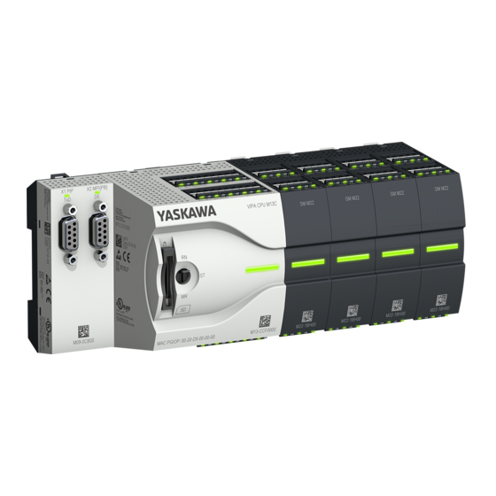
Manuals and User Guides for YASKAWA VIPA System MICRO. We have
1
YASKAWA VIPA System MICRO manual available for free PDF download: Manual
YASKAWA VIPA System MICRO Manual (325 pages)
Brand:
YASKAWA
| Category:
Computer Hardware
| Size: 14 MB
Table of Contents
Table of Contents
3
1 General
8
Copyright © VIPA Gmbh
8
About this Manual
9
Safety Information
10
2 Basics and Mounting
11
Safety Information for Users
11
System Conception
12
Dimensions
13
Mounting
14
Mounting CPU
14
Mounting the Extension Module
17
Mounting Periphery Module
18
Wiring
19
Wiring CPU
19
Wiring Periphery Module
23
Demounting
25
Demounting CPU
25
Demounting the Extension Module
29
Demounting Periphery Module
30
Installation Guidelines
33
General Data
35
3 Hardware Description
37
Properties
37
Structure
38
System MICRO CPU M13C
38
Interfaces
39
Leds
43
Memory Management
47
Slot for Storage Media
47
Buffering Mechanisms
48
Operating Mode Switch
48
Option: Extension Module EM M09 2X Serial Interface
49
HB400 | CPU | M13-CCF0000 | en
50
Technical Data
51
Technical Data CPU
51
Technical Data EM M09
64
4 Deployment CPU M13-CCF0000
65
Assembly
65
Start-Up Behavior
65
Addressing
66
Overview
66
Default Address Assignment of the I/O Part
66
Option: Addressing Periphery Modules
67
Hardware Configuration - CPU
68
Hardware Configuration - System MICRO Modules
70
Hardware Configuration - Ethernet PG/OP Channel
71
Take IP Address Parameters in Project
72
Setting Standard CPU Parameters
76
Parameterization Via Siemens CPU
76
Parameter CPU
77
Setting VIPA Specific CPU Parameters
80
Project Transfer
81
Transfer Via Ethernet
81
Transfer Via Memory Card
82
Option: Transfer Via MPI
82
Accessing the Web Server
85
Device Web Page
85
Webvisu Project
89
Operating Modes
91
Overview
91
Function Security
93
Overall Reset
94
Overall Reset by Means of the Operating Mode Switch
94
Overall Reset by Means of the Siemens SIMATIC Manager
94
Actions after the Overall Reset
94
Firmware Update
96
Reset to Factory Settings
97
Deployment Storage Media - VSD, VSC
98
Extended Know-How Protection
101
CMD - Auto Commands
102
Control and Monitoring of Variables with Test Functions
104
Diagnostic Entries
105
5 Deployment I/O Periphery
106
Overview
106
Address Assignment
107
Analog Input
108
Properties
108
Analog Value Representation
108
Wiring
109
Parametrization
110
Digital Input
111
Properties
111
Wiring
111
Parametrization
112
Status Indication
113
Digital Output
115
Properties
115
Wiring
115
Parametrization
116
Status Indication
116
Counting
118
Properties
118
Wiring
118
Proceeding
120
Parametrization
121
Counter Operating Modes
126
Counter - Additional Functions
133
Diagnostics and Interrupt
139
Frequency Measurement
140
Properties
140
Wiring
141
Proceeding
142
Parametrization
142
Status Indication
144
Pulse Width Modulation - PWM
146
Properties
146
Wiring
146
Proceeding
147
Parametrization
147
Status Indication
149
Pulse Train
151
Properties
151
Wiring
152
Proceeding
152
Parametrization
153
Status Indication
154
Diagnostic and Interrupt
155
Overview
155
Process Interrupt
155
Diagnostic Interrupt
157
6 Deployment PG/OP Communication - Productive
163
Basics - Industrial Ethernet in Automation
163
Basics - ISO/OSI Reference Model
164
Basics - Terms
166
Basics - Protocols
167
Basics - IP Address and Subnet
168
Fast Introduction
170
Hardware Configuration
170
Configure Siemens S7 Connections
171
Configure Open Communication
176
7 Deployment PG/OP Communication - PROFINET
179
Basics PROFINET
179
PROFINET Installation Guidelines
181
Deployment as PROFINET IO Controller
182
Steps of Configuration
182
Commissioning and Initialization
183
Configuration PROFINET IO Controller
183
Configuration PROFINET IO Device
185
Deployment as PROFINET I-Device
186
Steps of Configuration
186
Installing the GSDML File
187
Configuration as I-Device
188
Configuration in the Higher-Level IO Controller
189
Error Behavior and Interrupts
190
Mrp
193
Topology
194
Device Replacement Without Exchangeable Medium/Pg
195
Commissioning and Start-Up Behavior
196
PROFINET Diagnostics
197
Overview
197
Diagnostics with the Configuration and Engineering Tool
197
Diagnostics During Runtime in the User Program
197
Diagnostics Via ob Start Information
199
Diagnostics Status Indication Via Ssls
199
PROFINET System Limits
201
8 Option: Ptp Communication
202
Fast Introduction
202
Principle of the Data Transfer
203
Ptp Communication Via Extension Module EM M09
204
Parametrization
207
FC/SFC 216 - SER_CFG - Parametrization Ptp
207
Communication
208
FC/SFC 217 - SER_SND - Send to Ptp
208
FC/SFC 218 - SER_RCV - Receive from Ptp
208
Protocols and Procedures
208
Modbus - Function Codes
212
9 Option: Deployment PROFIBUS Communication
216
Fast Introduction
216
PROFIBUS Communication
217
PROFIBUS Communication Via Extension Module EM M09
218
Deployment as PROFIBUS DP Slave
220
PROFIBUS Installation Guidelines
222
10 Configuration with VIPA SPEED7 Studio
225
SPEED7 Studio - Overview
225
SPEED7 Studio - Work Environment
226
Project Tree
228
Catalog
229
SPEED7 Studio - Hardware Configuration - CPU
231
SPEED7 Studio - Hardware Configuration - Ethernet PG/OP Channel
232
SPEED7 Studio - Hardware Configuration - I/O Modules
234
Deployment I/O Periphery
235
Overview
235
Analog Input
235
Digital Input
237
Digital Output
237
Counter
238
Frequency Measurement
242
Pulse Width Modulation - PWM
244
Pulse Train
246
Deployment Web Visualization
248
Activate Webvisu Functionality
249
Webvisu Editor
249
Start-Up of the Webvisu Project
252
Access to the Webvisu
253
Status of the Webvisu
253
SPEED7 Studio - Project Transfer
254
Transfer Via MPI
254
Transfer Via Ethernet
256
Transfer Via Memory Card
257
11 Configuration with TIA Portal
258
TIA Portal - Work Environment
258
General
258
Work Environment of the TIA Portal
259
TIA Portal - Hardware Configuration - CPU
259
TIA Portal - Hardware Configuration - Ethernet PG/OP Channel
263
Take IP Address Parameters in Project
264
TIA Portal - VIPA-Include Library
268
TIA Portal - Project Transfer
269
Transfer Via Ethernet
269
Transfer Via Memory Card
269
Option: Transfer Via MPI
270
Appendix
272
A System Specific Event Ids
274
B Integrated Blocks
322
CSSL Partial List
325
Advertisement
Advertisement
Related Products
YASKAWA VS-616 Series
YASKAWA VS-676 Series
YASKAWA VIPA System MICRO M13-CCF0000
YASKAWA VIPA HMI
YASKAWA VIPA System SLIO
YASKAWA VIPA SPEED7
YASKAWA VIPA SLIO SDI
YASKAWA VIPA TP-smart
YASKAWA VIPA TP 612C RFID
YASKAWA VIPA HMI 62M-JIDR
YASKAWA Categories
Controller
DC Drives
Servo Drives
Robotics
Control Unit
More YASKAWA Manuals
Login
Sign In
OR
Sign in with Facebook
Sign in with Google
Upload manual
Upload from disk
Upload from URL