
Related Manuals for Baja WD250U


Summary of Contents for Baja WD250U
- Page 1 WD250U Service Manual For any questions please contact Baja Motorsports at 888-863-2252...
-
Page 2: Table Of Contents
Content Content...........................2 Chapter I General description..................6 Section 2 Special tools, instruments & meters.............. 7 (I) Special tools....................7 Section 3 Identification code, label of model and engine No........9 Section 4 Points for attention in maintenance..............9 Section 5 Specification....................13 I. How to use conversion table of unit............... 13 (1) How to use conversion table................ - Page 3 Section 3 Maintenance and adjustment of vehicle body..............44 (I) Wear inspection of front and rear brake................44 (II) Adjustment of front brake....................44 (III) Adjustment of free clearance of left lever and rear brake pedal........45 (IV) Position adjustment of steering lever................47 (V) Lubricating oil level inspection of rear driving gearcase..........
- Page 4 Section 3 Rear wheel/Rear brake/Rear wheel axle..............81 (I) Removal steps....................... 83 (II) Inspection stepes....................85 (III) Installation steps....................88 Section 4 Steering operation system..................92 (I) Removal steps of steering bar................93 (II) Removal steps of steering vertical column welding..........94 (III) Inspection content....................
- Page 5 Section 2 Inspection and maintanence of engine................159 Section 3 Assembly and adjustment of engine................... 183 (I) Closing assembly of left & right crankcase..............183 (II) Assembly of right crankcase.................... 187 (III) Assembly of left crankcase..................... 196 (IV) Selection and installation of adjusting washer............... 207 (V) Assembly of cylinder head....................
-
Page 6: Chapter I General Description
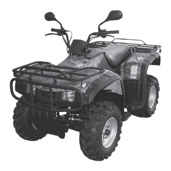
Chapter I General Description Section 1 Description 1. Front wheel 2. Headlight 3. Forward/Reverse lever 4. Shift pedal 5. Fuel valve 6. Hand-operated lever 7. Air choke 8. Taillight 9. Rear wheel 10. Rear luggage carrier 11. Exhaust silencer 12. Cushion 13. -
Page 7: Section 2 Special Tools, Instruments & Meters
Section 2 Special tools, instruments and meters (I) Special tools There are special tools needed to properly adjust and assemble this unit. These tools are intended to prevent maintenance defects and damage. 1. Wrench for valve adjustment, mainly used to adjusting the valve clearance. Specification: 3mm, 90890-01311 2. - Page 8 (II) Instruments and meters The following instruments and meters can be selected with reference to the same type of vehicle.
-
Page 9: Section 3 Identification Code, Label Of Model And Engine No
Section 3 Identification code, label of model and engine No. Identification code Engraved in the left or right side of the front supporting main tube of engine of frame Engine No. This is engraved on the top middle part of the right crankcase of engine. - Page 10 4. Clip 4.1 Before assembling, check all the clips carefully. Replace with a new one after removing from piston pin. When mounting clip ring (1), make the sharp end face (2) on the opposite position of impacted face (3) of clip. (see figure at left) 5.
- Page 11 7. Check of electric parts 7.1 Make sure there is no rust, dirt or moisture at the connection, if there is blow it dry or clean. 7.2 The electrolyte inside the battery is corrosive, take extra precautions as to not get this on your body.
- Page 12 B. If there is slack in the joint, bend the plug pin upward, then connect with connector plug (see figure 7.5) 7.6 Before mounting the new fuse, check if the load of fuse on the components are correct, especially the portion being broken regularly, then mount the fuse having proper current value.
-
Page 13: Section 5 Specification
Section 5 Specification I. How to use conversion table of unit (1) How to use a conversion table All the specified documents in this manual are taken SI and Metric as unit. With the following conversion table, metric unit could ne conversed into imperial unit. Metric Multiply Imperial... -
Page 14: Ii. Basic Specification
II. Basic specification Item Specifications Item Specifications Dimension: Shifting type Overall length 1960mm 1st speed 34/12(2.833) Overall width 1010mm 2nd speed 34/19(1.789) Overall height 1120mm 3rd speed 29/22(1.318) Height of cushion 780mm 4th speed 26/25(1.040) Axle base 1160mm 5th speed 23/28(0.821) Front wheel distance 785mm Reverse gear 73/22x34/12x19/18x46/11(41.5) -
Page 15: Iii. Atv Body
III. ATV body Item Standard Limit Steering system Powder metallurgy sliding Type of steering bearing bearing Type Spock rim, tubeless tire Material of rim Steel plate Front Size of tire AT22x7-10 Wheel Size of rim AT 10x5.5 Radial runout of rim 2.0mm Lateral swing of rim 2.0mm... -
Page 16: Iv. Electric System
III. ATV body Item Specification Limit Elastic coefficient of spring K1 10N/mm/0-117mm Free length of suspending spring 293mm Front suspension system Stroke of shock absorber 117mm Pre-tension force of spring is Not adjustable adjustable or not Elastic coefficient K2 49N/mm/8-85mm Free length of suspending spring 263mm Rear suspension Assembling length... - Page 17 IV. Electric system Item Standard Resistence of induction coil/color At 20˚C (68˚F), 189-231Ω Blue-black Magneto Resistence of source coil/color At 20˚C (68˚F), 470-530Ω yellow/green-red Type of C.D.I. Electric capacity contactless type No-loading adjusting voltage 14.1-14.9V Rectifier Voltage-resisting value 200V Type A·C magneto Charging Rated output voltage...
-
Page 18: V. Maintenance Specification Of Engine
V. Maintenance Specification of Engine Item Standard Limit Axle Drive Meshing clearance of last end gear 0.1-0.2mm Meshing clearance of middle gear (forward) 0.1-0.2mm Meshing clearance of middle gear (backward) 0.10-0.25mm Lubrication system: Type of oil filter Wire filter net Type of oil pump Rotor type, pressure splash type lubrication Clearance of side 0.04-0.09mm... - Page 19 V. Maintenance Specification of Engine Item Standard Limit Valve spring: Outside spring: Free length: intake/exhaust 37.2mm Setting length when valve is closed: 32.0mm Compressing pressure when assembling:intake/exhaust 162.8-200.1N Limit value of sqaureness:intake/exhaust 2.5˚/1.6mm Twisting direction of spring (top view):intake/exhaust clockwise Valve, valve seal, valve guide Valve clearance (it’s cold): intake 0.05-0.09...
- Page 20 V. Maintenance Specification of Engine Item Standard Limit Piston Piston size “D” 70.92-70.97mm Measuring point “H” (from bottom line of piston lower portion) 4.0mm Piston offset 0.5mm Direction of piston offset Inward Clearance between piston and cylinder 0.04-0.006 0.15mm Outside diameter of piston pin 15.991-16.000mm Inside diameter of pin hole 16.002-16.013mm...
-
Page 21: Section 6 Wiring Diagram Of Atv
Section 6 Wiring diagram (I) Technical explanation and requirements, details of relative component. 1. Technical explanation [W] After putting the fuel tank vent tube though [A] Main switch wire, indicator wire, mileage the hole of main switch, lead it to the lower meter wire (mounting digital mileage meter) right side of steering bar, then put it through the must be put through the guide grip of holding wire hook on the frame. - Page 22 3. Details of relative component [U] When assembling, mount supporting pad of vent-tube should be free of leaks, and pay at- Ser. Code Name tention to let the direction of mark upward (see view D). SSA0-000512-0 Wire clip 4 [N] Taillight wire must be put through the slot SSA0-000511-0 Wire clip 3 hole preset by tool kit from the bottom of tool SSA0-000510-0 Wire clip 2...
-
Page 23: (Ii) Wiring Diagram (1)
(II) Wiring diagram (1) -
Page 24: (Iii) Wiring Diagram (2)
(III) Wiring diagram (2) -
Page 25: (Iv) Wiring Diagram (3)
(IV) Wiring diagram (1) - Page 26 Section 7 Requirements for torque fastening (I) ATV Body Torque value of fasteners Locking component and location on ATV Hard- Size of Qty Nm m·kg ft·lb ware thread Front wheel rim & front brake hub M10x1.25 8 Front brake hub & steering vertical post M12x1.25 2 Front brake cam arm & cam shaft M6x30 Front brake &...
- Page 27 (I) ATV Body Torque value of fasteners Locking component and location on ATV Hard- Size of thread Qty Nm m·kg ft·lb ware Rear fender & rear luggage carrier Bolt M8x16 Left & right foot rest & frame Bolt M6x20 Left & right foot rest & frame Bolt M10x22 Supporting weld in foot rest &...
- Page 28 (II) Engine Torque value of fasteners Locking component and location on Hardware Size of Qty Nm m·kg ft·lb Remarks engine thread Observing screw hole of cylinder head cap nut Cylinder head flange bolt apply oil to washer Cylinder head & cylinder Bolt Sprocket cover Screw Valve cover Bolt...
- Page 29 (II) Engine Torque value of fasteners Locking component and location on Hardware Size of Qty Nm m·kg ft·lb Remarks engine thread Exhaust pipe Bolt Crankcase (closing case) Screw Left side cover Screw Left crankcase cover Screw Right crankcase cover Screw Bearing clamp of right crankcase cover Screw apply tighten- ing agent...
-
Page 30: Engine
(II) Engine Torque value of fasteners Locking component and location on Hardware Size of m·kg ft·lb engine thread Shift pedal Bolt Megneto stator Screw Neutral switch Reverse gear switch Hand-started driving disc Screw pin (III) General torque specification General torque specification (standard screw) This figure is a screw locking specification drawn by International Standard Association. -
Page 31: Section 8 Lubrication
Section 8 Lubrication (I) Lubrication oil way... -
Page 32: Lubrication Diagram
(II) Lubrication diagram 1. Oil draining plug 8. Oil pump driving gear 2. O-ring 9. Camshaft 3. Compressing spring 10. Crankcase 4. Rough filter 11. Crank 5.Oil pump washer 12. Spindle 6. Oil pump assy 13. Driving shaft 7. Oil pump driven gear 14. - Page 33 (II) Lubrication diagram 1. Single-direction valve 8. Single-direction bearing 2. Engine oil fine filter (automatic centrifugal clutch) 3. Engine oil fillter cover 9. Crank pin 4. O-ring 10. Crank pin 5. Clip 11. Spindle 6. Camshaft 12. Driving shaft 7. Rocker...
-
Page 34: Section 9 Lubrication Point And Type Of Lubricants
Section 9 Lubrication point and type of lubricants (I) Lubrication point and type of lubricants (ATV body) Lubricant point Type of lubricants Lip of oil seal (full) Light lithium-base grease O-ring (full) Light lithium-base grease Steering shaft (upper end, lower end) Light lithium-base grease Ball connection of steering pushing rod Light lithium-base grease... - Page 35 (II) Lubrication point and type of lubricants (Engine) Lubricant point (name of component) Type of Lubricant Lip of oil seal Light lithium-base grease (Crank,shift,gearshaft,spindle,shiftgear operation shaft) All bearing Lubricating oil (Crank,spindle,driving shaft,output shaft,balancing shaft,shift gear camshaft,pneumatic camshaft) O-ring (Contact position of o-ring) Light lithium-base grease Lubricating oil Stem end of intake &...
-
Page 36: Engine
Chapter II Maintenance adjustment of vehicle NOTE: The correct maintenance and adjustments are necessary to ensure the vechicle’s in normal driving condition. The repair personnel should be familiar with the contents of this article. Section 1 Periodic Maintenance/Lubrication Everytime Every Item Requirement 1MO 3MO 6MO 6MO 1YR... -
Page 37: Section 2 Disassembly And Assembly Of Cushion, Fender And Fuel Tank
Section 2 Disassembly and assembly of Cushion, Fender and Fuel tank (I) Cushion 1.Disassembly 1- Place the vehicle on level ground. 2- Disassemble the cushion (1) : Pull the cushion lock lever (2) up, then raise the rear of cushion. 2. -
Page 38: (Ii) Rear Fender
(II) Rear fender 1. Disassembly 1- Place vehicle on level ground. 2- Disassemble the rear luggage carrier (1) and installing bushing (2) 3- Disassemble the cushion (3) (see cush- ion disassembly in this section). 4- Disconnect the negative wire (5) and positive wire (4) of battery. - Page 39 2. Installation Reverse procedure for “Disassembly”. Pay at- tention to the following points: 1- Install: Rear fender (1) Bolt (2) (rear fender and frame). The torsion in 7N·m. Bolt (3) and rubber hood of protecting plate (rear fender and frame). The torsion is 7N·m. 2- Install: a.Battery (1) b.Battery clamp plate (2)
-
Page 40: (Iii) Fuel Tank
(III) Fuel tank 1. Disassembly 1- Place the vehicle on level ground. 2- Remove the cushion (see “cushion disas- sembly” section) 3- Remove the air hose on the fuel tank cover 4- Remove: a.Bolt (2) , flat washer 30, installing bush- ing of upper cover of fuel tank, washer and rubber hood 2 of fuel tank. - Page 41 2. Installation Reverse procedure for “Disassembly”. Pay close attention to the following points: 1- Install the fuel tank (1) 2- Connect a. Air inlet pipe (2) and hose (4) b. Supporting pad (3) of air pipe and air rub- ber pipe (4) CAUTION: The convext part on the ring should be facing forward when installing the supporting pad...
-
Page 42: Iv) Front Fender
(IV) Front fender 1. Disassembly: 1- Place the vehicle on level ground. 2- Disassemble the front luggage carrier (1) 3- Disassemble the front guarding plate (2) 4- Cut off the connecting wire (1) of head- light (from connecting point). 5- Disassemble the bumper (2) 6- Disassemble the front fender (1) - Page 43 2. Installation Reverse procedure for “Disassembly”. 1- Install: a. Front fender (1) b. Bolt (2) . The fastening torque is 7N·m c. Bolt (3) , rubber hood of protecting plate. The fastening torque is 7N·m 2- Install the bumper (1) . The fastening torque of bolt (bumper and frame) is 16N·m.
-
Page 44: Section 3 Maintenance And Adjustment Of Vehicle Body
Section 3 Maintenance and Adjustment of vehicle body (I) Wear inspection of front and rear brake 1.Check the front brake 1- Stop the vehicle using the front brake 2- Check: • Brake pad (1) between caliper (2) and disc • If pads are worn, replace. Refer to “Front wheel and front brake”... -
Page 45: (Iii) Adjustment Of Free Clearance Of Left Lever And Rear Brake Pedal
2. Adjustment Adjusting procedure of the free clearance of right lever: • Loosen the lock nut (1) , rotate the cable adjusting screw (2) clockwise to reduce the tension of front brake cable. • Lift the front end from the ground, rotate the two front wheels. - Page 46 2. Adjust • Free clearance of left lever. • Free clearance of rear brake pedal. Adjusting procedure: CAUTION: Before adjusting, depress the rear brake pedal 2-3 times. • Loosen the locking nut (1) completely, and screw in the cable adjusting screw (2) completely.
-
Page 47: Iv) Position Adjustment Of Steering Lever
(IV) Position adjustment of steering lever • Position adjusting procedure of steering lever. • Place the vehicle on level ground. • Change gears to 1st gear and pull the steering lever (1) to reverse gear position. • Loosen the locking nut (2) •... - Page 48 (VI) Replacing engine oil of rear driving gear case. 1. Place the vehicle on level ground. 2. Place an oil catcher under the rear driving gear case. 3. Remove: • Lower cover of gear case • Oil fillin screw plug •...
-
Page 49: (Vii) Rubber Sleeve Inspection Of Rear Wheel Fork
(VII) Rubber sleeve inspection of rear wheel fork check • Rubber sleeve (1) If damaged or worn, replace it. Refer to chapter 3 section 6 “rear shock absorber and rear wheel fork”. (VIII) Inspection of steering system 1. Place the vehicle on level ground 2. - Page 50 (IX) Adjustment of toe-in on front wheels. 1. Rest the vehicle on level ground. 2. Measurement: • Toe-in, adjust if not in specification. Adjustment steps for toe-in • Mark the center of tire thread on both front wheels • Lift the front end to keep force off wheels •...
-
Page 51: (X) Inspection Of Front/Rear Shock Absorber
(X) Inspection of front/rear shock absorbers 1. Rest the vehicle on level ground 2. Inspection: • Ball joint assy (1) (upper part of front shock absorber). If broken or damaged, replace the front shock absorber. • Rear shock rod (2) (rear shock absorber) If broken or damaged, replace the rear shock absorber. -
Page 52: (Xii) Inspection Of Tire
(XII) Inspection of tire WARNING: This vehicle is equipped with low pressure tires, so correct filling pressure and keeping the proper pressure is very important. • Tire characteristics 1) Quality charicteristics of tire will affect the driv- ing reliability of ATV. The following types of tires are approved by the manufacturer and can be used safely. -
Page 53: (Xiii) Inspection Of Rim
1. Measurement • Tire pressure (normal atmospheric temperature): If out of specification, adjust. CAUTION: • The manometer (1) is included with the tool kit (Nver use high pressure). • If there is any dust or debris in the tire pressure manometer you will not receive a correct reading. -
Page 54: Section 4 Maintenance And Adjustment Of Electrical Appliance
Section 4 Maintenanace and Adjustment of Electrical Appliance (I) Inspection of battery WARNING: The electrolyte is dangerous and includes sulphuric acid, so it is poisonous and corrosive. • Please operate by the following steps: a. Avoid touching any part of your body with the electrolyte especially your eyes. -
Page 55: (Ii) Inspection Of Fuse
5. Inspection of battery If damaged, replace it 6. Installment of battery (3) 7. Connect • Battery electrode (positive electrode (1) negative electrode (2) ) First connect the positive electrode (1) 8. Installment: a. Battery clamp plate (4) b. Cushion (II) Inspection of fuse CAUTION: Close the main switch when checking or replacing... -
Page 56: (Iii) Replacement Of Headlight Lamp
2. Replacement of bad/old fuse Replacement steps: • Cut off engine and circuit • Install the new fuse. • Start the power for electrical appliance inspection. • If the fuse is not responding check the system again (Refer to “Electrical Appliance” of chapter 4) 3. - Page 57 6. Installment • Lamp (1) CAUTION: Be sure that the projective part of the lamp (2) is engaged with the convex groove (3) on the light seat. CAUTION: Never touch the glass part otherwise the lamp will loose illuminating value. If there are some oils on it clean off with cloth mixed with alcohol.
-
Page 58: Section 5 Maintenance And Adjustment Of Engine
Section 5 Maintenance and Adjustment of Engine (I) Adjustment of clutch Adjustment steps: a. Loosen the locking nut (1) b. Turn the adjusting screw rod (2) counterclock- wise slowly up to be unable to turn, then turn 1/8 clockwise, and fasten the adjusting screw rod 2 to this position and tighten up the locking nut 1 with the torque of N ·m. - Page 59 3. Removal a. Air filter core (1) b. Foam supporting cylinder (2) CAUTION: Never start the engine without filter, otherwise the piston and cylinder will be overworn. 4. Inspection a. Air filter core (1) b. Foam supporting cylinder (2) If damaged replace it. 5.
-
Page 60: (Iii) Inspection Of Spark Plug
(III) Inspection of spark plug 1. Rest the vehicle on level ground and clean the spark plug with compressed air to avoid the dust entering the engine. 2. Remove the spark plug (1) The standard spark plug: DTRTC, if not correct, replace it. -
Page 61: (Iv) Adjustment Of Idle Speed
(IV) Adjustment of idle speed 1. Rest the vehicle on level ground 2. Start the engine and warm it at idle speed of 1000-2000r/min, after several minutes, increase the engine speed to 4000-5000r/min. 3. Set the specified idle speed through adjusting the throttle adjusting screw (1) . -
Page 62: (Vi) Adjustment Of Speed Limiter
(VI) Adjustment of speed limiter: The speed limiter can limit the throttle in full open- ing condition when the throttle grip is pulled to the max position, screwing the adjuster inward can stop increasing the speed. 1. Adjust speed limiting length (a) Adjustment steps: a. -
Page 63: (Vii) Adjustment Of Valve Clearance
(VII) Adjustment of valve clearance CAUTION: The valve clearance should be adjusted only after the engine is cold, the valve clearance should be adjusted when the piston is at the end point posi- tion of compress stroke. 1. Removal: 1) Rest the vehicle on level ground 2) Remove a. - Page 64 b. Make the mark “T” on the rotor align with the mark on the crankcase. When aligned the piston ties in Top Dead Center (TDC) c. Inspection of top dead center in pressure stroke: (i) When the mark (1) on the rotor is align with mark (2) on the crankcase, the two arms must be clear.
-
Page 65: (Viii) Adjustment Of Timing Chain Tension
3. Installation: Follow the opposite steps of “Removal”. (1) Mount: a. Valve cap (1) (side of outlet door) b. Valve cap (2) ( side of inlet door) CAUTION: (i) Project of valve cap (1) (2) should be up (ii) Check if the o-ring (4) is damaged, if so re- place immediately. -
Page 66: (Ix) Inspection Of Ignition Timing
(IX) Inspection of ignition timing Notice: Before you check the correct timed ignition, adjust the engine idle speed and free clearance of the throttle grip to the correct position. 1. Put the vehicle on level ground 2. Start the engine for pre-heating, and then stop the engine. - Page 67 (X) Measurement of compressive force CAUTION: Inadequate compressive force will reduce the en- gine performance. Before measuring the compressive force, the valve clearance should be adjusted first (refer to “Adjust- ment of valve clearance” section). 1. Put vehicle on level ground 2.
-
Page 68: (Xi) Inspection Oil Quantity Of Engine
d. If pressure drops below min. value: (i) Drop some oil to active cylinder. (ii) Measure the pressure again Compressing force (The machine oil has been filled in the cylinder) Compressure read Reason Read is higher Piston or ring is than filling before worn/damaged Read is equal when... - Page 69 b. Completely remove the dipstick (1) and clean it before inserting it back into the oil hole. c. Remove the dipstick (1) . Make certain that the oil level is between the max value (2) and min value (3) . d.
- Page 70 6. Inspection If O-ring (1) , compressor spring (2) , rough filter (3) , or fine filter (4) is damaged, it should be replaced. 7. Cleaning Use cleanser to clean the compressor spring (2) , filter (3), filter net (4), crankcase filter plug (5), and filter nut cap (6) .
- Page 71 11. Mount dipstick 12. Stop pre-heating engine after 5 minutes or more. 13. Check the oil level and if it is leaking 14. Check oil flow Inspection steps: a. Lightly loosen bolt (1) of cylinder head. b. start engine for racing until oil runs from the oil tunnel.
-
Page 72: Chapter Iii Repair And Maintenance Of Vehicle Body
Chapter III Repair and Maintenance of Vehicle Body Section 1 Rear driving gearcase and driving shaft 8. Bearing 13. Bearing 18. Trans. shaft 1. Driving gear case cover 9. Oil seal 14. Bearing gasket 19. Circlip 2. O-ring 10. Bearing 15. O-ring 20. Rear joint 3. Oil seal 11. -
Page 73: (Ii) Inspection
(I) Trouble • Trouble judging guidance Performance Possible Reason 1. The vehicle appears to stop or there is irregular A. Damaged bearing axial run-out with an abnormal noise while the B. Improper clearance vehicle accelerates, decelerates, or is in idle state. C. -
Page 74: (Iii) Troubleshooting Table
It is necessary to check the rust of bearing if there is a great deal of metal or metal corpuscle on the oil draining screw plug so it does not cause a jam. CAUTION: It is normal for some metal corpuscle to be in the oil. 3. -
Page 75: (Iv) Disassembly
(IV) Disassembly WARNING: Ensure that the vehicle does not turn over by firmly supporting it. 1. Drain the rear driving gear case oil Refer to section 3, chapter 2, “Replacement of engine oil of rear driving gear case” 2. Disassemble 1) Cushion 2) Rear luggage carrier 3) Rear fender... - Page 76 1. Disassembly a. Remove: bolt (1) M6 bolt (2) M8 CAUTION: Loosen each bolt by ¼ circle and remove bolts alternately. b. Disassemble: 1) Rear driving gear case body (1) 2) Annular gear pad 3) Shift gear 4) Thrust plain pad c.
- Page 77 d. Disassemble With a soft hammer lightly tap the main driv- ing gear (1) and remove (with thrust pad (2) and bearing (3)) CAUTION: Remove the main driving gear first if it is nec- essary to replace the gear. Replace the original bearing thrust pad, do not reuse.
-
Page 78: (V) Inspection
(V) Inspection 1. Replace the main driving gear and shift gear if there are any caving, scratches, or wearing on the gear teeth of bevel gear pair (1) 2. Check oil seal (2) 3. Check the O-ring (3) Replace if damaged 4. - Page 79 (VI) Choice of main driving and shift gear pad 1. Main driving gear pad (1) choice: Use “A” = (a) - (b) to work out main driving gear pad thickness (a) =84 +/- engraved number on main driving gear (b) =83.5 +/- engraved number on driving gear case body CAUTION: The unit of numbers on the main driving gear and...
- Page 80 2. Choice of shift gear pad Shift gear pad (1) Choosing procedures: Work out the pad thickness “B” from following formula “B”= (c) + (d) - ( (e) + (f) ) (c) =45.5 adds or subtracts the number en- graved on the driving gear case body. (d) =1 adds or subtracts the number engraved on the driving gear case cover.
-
Page 81: (Vii) Installation
(VII) Installation: Reversal of “disassembly.” Make sure to pay attention to the following points: 1. Install the needle bearing (small) on main driving gear: Procedures: a. Warm the case body to 150°C b. Assemble the out circle of bearing with proper hold-down. -
Page 82: Section 3 Rear Wheel/Rear Brake/Rear Wheel Axle
Section 3 Rear wheel, rear brake, rear wheel axle Technical Parameter No. Item Parameter Tire specification AT22x10-10 Rim Dimension 8.5x10 Tire air pressure (Normal Temperature) Standard value 25KPa Min. value 22KPa Max. value 28KPa Runout Radial runout End face runout Wear limit of tire Wear limit of friction disk Rear brake hub wear limit... - Page 83 B. Right end of rear wheel 1 Rear brake hub 2 Brake shoe 3 Bearing block 4 Dust-proof seal 5 Air pipe 6 Rear brake cover assembly 7 Rear brake cam shaft 8 Brake indicating plate 9 Rear brake arm assembly...
-
Page 84: (I) Removal Steps
(I) Removal steps 1. Rest the motorcycle on a flat ground. Press the brake clip (1) . 2. Loosen the connecting nuts of front and rear wheels. 3. Stop up the front wheel with wood, then put a proper supporting article under the frame so as to lift the rear wheel and make the rear wheel leave the earth. - Page 85 8. Removal: (the Ser. No. as shown on the drawing) (1) Adjusting nut, pin and spring of rear brake arm and rear brake tension rod assy. 9. Removal: (2) Rear brake cable (3) Rear brake tension rod assy (4) Air pipe of rear brake 10.
-
Page 86: (Ii) Inspection Stepes
(II) Inspection steps: 1. Inspection When inspecting the real wheel, refer to “Tire Inspection”, “Rim Inspection” Section of chap- ter 2. 2. Measurement: a: radial run-out of rim b: Tire surface Refer to “Front wheel and Front Brake Inspec- tion” Section of this chapter 3. - Page 87 8. Inspection (The Ser. No. as shown on the drawing) 1 Inner surface of rear brake hub If there is some engine oil or scraped markings, remove it and treat it. The method of treat is as follows: Removal of engine oil: Clean with cloth dipped in volatile dilute or volatile solvent.
- Page 88 13. Measurement The radial run-out of the piston (a) on the rear wheel axle, if out of specification, replace it. Attached: The radial run-out limit of rear wheel axle: 1.5mm WARNING: If the axle is bent, do not straighten it force- fully.
- Page 89 (III) Installment steps: The reversal steps of “removal steps” are in- stallment steps. Pay attention to the following points when installing: 1. Lubrication part (1) Oil seal lip of rear wheel axle. (2) Bearing of rear wheel axle. The corresponding splint tooth of rear wheel axle.
- Page 90 5. Installment Cam shaft of rear brake (1) Indicating plate of brake (2) Rear brake arm assy (3) CAUTION: When installing the brake indicating plate (2) to rear brake cam shaft (1) , be sure to align the projective part (a) of brake indicating plate (2) with the concave part (b) of rear brake cam shaft (1) .
- Page 91 8. Installment Brake shoe assy 9. Lubrication Dust-proof seal Lubrication oil for dust-proof seal: lithium base grease. Warning The lubrication oil is not allowed to be used for brake shoe assy, the lithium base grease is used for rear brake hub splint groove. WARNING: The lubrication oil is not allowed to be used for splint on the right end of rear wheel axle,...
- Page 92 15. Installment split pin 4x30 (1) CAUTION: After fastening the torque, the nut on the rear axle is not allowed to be loose. If the nut con- cave groove is not aligned with the splint hole on the screw rod, align it by tightening up the nut.
-
Page 93: Section 4 Steering Operation System
Section 4 Steering Operation system (1) Upper holder of steering bar (2) Lower holder of steering bar (3) Steering vertical column welding (4) Steering vertical column holder (5) Seal ring (6) Bushing (7) Clip assy (8) Locking pad (9) Steering tension rod ball pin assy (10) Tension rod... -
Page 94: (I) Removal Steps Of Steering Bar
(I) Removal steps of steering bar 1. Removal Front luggage carrier Bumper Front fender Refer to chapter 2, section 2 2. Removal Main switch lock wire “Neutral” indicating light wire “Reverse” indicating light wire “High beam” indicating light wire Clutch switch wire 3. -
Page 95: (Ii) Removal Steps Of Steering Vertical Column Welding
(II) Removal steps of steering vertical column welding 1. Plain move (1) The locking part of locking pad as shown 2. Removal (2) Bolt M8x60 (3) Locking washer (4) Clip assy 3. Removal Install the steering vertical column with split pin 2.5x24 Nut M10 Washer 10... -
Page 96: (Iii) Inspection Content
(III) Inspection content 1. Check if the steering bar cracked, bent, or damaged. If it is, replace it. 2. Inspect the steering vertical column welding assy for any bends or damage. If there is, re- place it. WARNING: In order to avoid decreasing the performance of the steering vertical column, do not straighten it forcefully if it is bent. - Page 97 6. Adjustment Assembly length of tension rod Adjustment steps of tension rod assembly length 1- Loosen the connecting nut [A] [B] 2-Adjusting the assembly length of tension rod by rotating the tension rod. Attached: Tension rod assembly length @: 297mm [A] Right-handed thread [B] Left-handed thread Connect [C] position to the steering vertical col-...
- Page 98 2. Lubricate the steering vertical column hold- er (1) and seal ring (2) during installation of the steering vertical column welding. 3. Installment Install the seal ring (1) to the steering verti- cal column welding, then install bushing (2). Finally, install the steering vertical column holder (3).
- Page 99 7. Mounting split pin (1) CAUTION: Don’t loosen the nut after the torque is fixed. If the nut recess does not correspond with split pin hole on the double-screw bolt, tighten the nut to align them. WARNING: Always use new split pin 8.
-
Page 100: (V) Installation Steps Of Steering Bar
(V) Installation steps of steering bar 1. Install the lower holding seat (1) , steering tube (2) and upper holding seat (3) . WARNING: When tightening the bolt of holding seat, make sure clearance (b) is clear. Attached: bolt torque: 20Nm 2. -
Page 101: Section 5 Front Shock Absorber And Front Wheel Fork
Section 5 Front shock absorber and Front wheel fork (1) Front shock absorber (2) Left/right front seat assy (3) Left/right front wheel fork welding (4) Bushing unit... -
Page 102: (I) Disassembly
(I) Disassembly: 1. Take off front luggage carrier, bumper, and front fender. Refer to the second section of chapter 2 Disassemble the front wheel front brake hub, brake shoe unit, and front brake cap unit. Refer to “Dischargement of front wheel and front brake”... - Page 103 7. Check the free clearance of left/right front wheel fork Inspection step: a: Check the parts (1) of left/right front wheel fork on the frame. If it is bent, cracked, or worn, repair or replace the frame. b: Check the torque value of locking nut (2) on the left/right front wheel fork Attached: Nut torque: 45Nm c: Move the left/right front wheel fork from...
-
Page 104: (Ii) Inspection Steps
(II) Inspection step 1. Check the front shock absorber. If there is leakage, replace it. Check the universal joint. If it is cracked or damaged, replace the front shock absorber. Check spring, if it is fatigued or damaged, re- place the front shock absorber. (When check- ing, move the spring up and down). -
Page 105: (Iii) Installment Steps
(III) Installment steps The opposite steps of “Disassembly” are the mounting steps. The following must be paid attention to when mounting: 1. Lubricate the inner surface of bushing sub- assembly (1) . (lubrication oil is lithium base grease). 2. Fix nut (2) Nut torque: 45Nm CAUTION: Must ensure that the correction of bolt mount-... - Page 106 5. Mount the split pin (3) CAUTION: Don’t loosen the nut after marking the standard torque. If the recess on the nut does not corre- spond with split pin hole on the bolt, correct it by tightening the nut. WARNING: Must use new split pin.
- Page 107 CAUTION: Don’t loosen the nut after marking the standard torque. If the recess on the nut does not cor- respond with the split pin on the bolt, correct it by fixing the nut. WARNING: Must use new split pin (3) 10.
-
Page 108: Section 6 Rear Shock Absorber And Rear Wheel Fork
Section 6 Rear shock absorber and Rear wheel fork (1) Rear shock absorber (6) Oil sealing (2) Rubber washer assy of rear shock absorber (7) Bearing 30203 (3) Rear arm nut M22 (8) Rear wheel fork Assy (4) Rear arm joint bolt (9) Rubber tube (5) Axle bushing (10) Lower cap of gear case... -
Page 109: (I) Disassembling Steps
(I) Disassembling steps 1. Take off left rear wheel, rear wheel joint plate, right rear wheel, rear brake hub, rear brake, and rear axle. Refer to “Disassembly of rear wheel/rear brake and rear wheel axle” section in this chapter. 2. Take off lower cap (2) of gear case. 3. - Page 110 5. Take off nut (1) on the rear shock absorber, bolt (2), rear shock absorber (3) . 6. Take off rear brake tension spring (1) . 7. Take off dusty cap on rear arm axle. 8. Check the free clearance of rear wheel fork checking steps.
-
Page 111: (Ii) Checking Steps
9. Take off rear bush (1) 10. Take off driving axle clamp assy (front) (1), rear arm nut (right side) and rear arm joint bolt. 11. Take off rear wheel fork assy (1) . (II) Checking steps 1. Check a: If rear shock absorber is leakage, if any, replace it. - Page 112 2. Check if the rear wheel fork assy is cracked, bent, and damaged. If any, replace it. Check if the rear wheel bush is cracked, bent, and damaged. If there is one of these problems, replace it. 3. Check the gear case lower cap. If there are any cracks, bends, or damage, replace this part.
-
Page 113: (Iii) Mounting Steps
Take off bearing (3) with usually bearing tool. The reverse step of “bearing and oil sealing replacing step” is the mounting step of new bearing and new oil sealing. CAUTION: Use a pressure tooling (4) which is matched with outer diameter of bearing race (7) and oil sealing. - Page 114 3. Fix the rear arm joint bolt (1) (left), rear arm joint bolt (2) (right) and bush (3) . Fixing steps: a: Fix the left rear arm joint bolt (1) by stan- dard torque. Attached: Bolt torque value: 130Nm b: Fix the right rear arm joint bolt (2) until it makes contact with its bush (3) .
- Page 115 8. Mount the rear driving gear case sub-assem- bly (1) Refer to “Installation of rear driving gear case sub-assembly and driving shaft” section of this chapter. 9. Mount the rear wheel axle, rear brake hub, right rear wheel, rear wheel joint plate and left rear wheel.
-
Page 116: Chapter Iv Electric Appliance
Chapter IV Electric Appliance Section 1 Electric Assembly 1. CDI assembly 15. Battery 2. Rectifier 22. Main switch lock 5. Safety. starting relay 24. Neutral indicating assembly 6. Power off relay 26. Reverse indicator assembly 7. High voltage coil 28. High beam indicator assembly 11. -
Page 117: Section 2 Inspect Switch
Section 2 Inspect switch (I) Inspect switch Make certain the wire end is on the pocket mul- timeter. If there are any problems replace the switch Pocket multimeter • Turn the multimeter to “O” • Turn the multimeter to “Ωx1” when inspecct- ing the circuit •... -
Page 118: (Ii) Inspect The Switch Circuit
(II) Inspect the switch circuit Refer to “Inspect switch”. Inspect if the circuit between wire and wire end is on. If the contact is poor or the circuit is off-repair or replace 1 Light switch 6 Reverse switch 2 Engine stop switch 7 Neutral switch 3 Starting switch 8 Protecting device... - Page 119 Section 3 Check Lamp (headlight) Check the lamp condition 1. Remove the lamp CAUTION: Pay attention to support the lamp. Do not pull the lead wire, otherwise it will brake. WARNING: When the headlight illuminates, remove your hand from the lamp, it will be very hot. Do not touch until it has cooled down.
-
Page 121: Section 4 Troubleshooting The Ignition System Failure
Section 4 Troubleshooting the Ignition System failure If the ignition system does not work (No spark) Check: 1. Spark plug 6. Main switch 2. Ignition spark clearance 7. Resistence value of triggering coil 3. Resistence value of spark plug cap 8. Resistence value of charge coil 4. - Page 122 2. Ignition spark clearance • Remove the spark plug cap • Connect as shown in figure (1) Spark testing instrument (2) Spark plug cap (3) Spark plug • Turn the main switch to the “ON” position • Check the ignition spark clearance •...
- Page 123 • Inspect if the resistence of primary coil con- forms to specification Primary coil resistence At 20˚C(68˚F), 0.43~0.5Ω • Connect the multitester (Ωx1K) to ignition coil • Inspect if the second coil resistence conforms FAIL to specification Secondary coil resistence Replace ignition coil At 20˚C(68˚F), 4.6~7.6KΩ...
- Page 124 8. Resistence value of charge coil • Remove the corresponding connector of charge coil from cable. • Connect the multitester (Ωx100) to wire end of charge oil Multitester pen (+) - yellow/green wire end(1) Multiteser pen (-) - red wire end (2) Inspect if the resistence value is not at the FAIL specification...
-
Page 125: Section 5 Running Starting Circuit
Section 5 Running of Starting circuit The starting circuit of this vehicle including starting motor, cut-off relay, rear brake switch and neutral switch. If the main switch is in position, the starting motor could be operated only at the following conditions: • Driving device is in the neutral postion (neutral switch is closed) •... -
Page 126: Section 6 Troubleshooting Electric Starting System
Section 6 Troubleshooting electric starting system If starting motor does not work • Check 1. Safety 6. Main switch 2. Battery 7. Neutral switch 3. Starting motor 8. Rear brake switch 4. Cut-off relay 9. Starting switch 5. Starting relay 10. Circuit connection (entire startinf system) •... - Page 127 No rotation Repair or replace starting motor Operation 4. Power off relay • Remove relay from cable • Connect portable multitester (Ωx1) and bat- tery (12V) to end of wire on relay Battery end (+) - red/white wire end (1) Battery end (-) - green/yellow wire end (2) Mutlitester pen (+) - red/white wire end (1) Multitester pen (-) - blue/white wire end (3)
- Page 128 6. Main switch FAIL Refer to “Check system” Replace main switch PASS 7. Neutral switch FAIL Refer to “Check system” Replace neutral switch PASS 8. Rear brake switch FAIL Refer to “Check system” Replace rear brake switch PASS 9. Starting switch FAIL Refer to “Check system”...
-
Page 129: Section 7 Starting Motor
Section 7 Starting Motor Sequence Name of Part Remark Starting motor disassembly Starting motor wire Remove the components Starting motor connecting wire according to sequence. Starting motor o-ring Same disassembly as above Bracket 1 Washer/pad Refer to “Starting motor” Bracket 2 installation Electrice brush/spring Armature winding Installing sequence in re- Magnet steel... -
Page 130: Section 8 Check Starting Motor
Section 8 Check Starting Motor 1. Check • Reverser If dirty clean with #600 sand paper 2. Measure • Reverser diameter (a) Does not meet specification-change the starting motor Outer diameter 28mm(1.10in) (Wear range) 27mm(1.06in) 3. Measure • Mica cut sheet (b) Does not meet specification- scrape the mica with square scraper Mica cut sheet: 0.7mm(0.028in) Scrape the mica with square scraper to get proper... - Page 131 5. Measure • Length of brush Out of specification-replace it Length of brush:10mm(0.39in) Range of wear: <6mm(0.14in) 6. Measure • Brushing spring force Fatigue/out of specifications-replace entire device Brushing spring force:326~970g(3.2~3.8N) 7. Check • Oil sealing • Bushing • O-ring Worn or damaged-replace Installation of starting motor: 1.
-
Page 132: Section 9 Battery Will Not Hold Charge
Section 9 Battery will not hold charge Check: 1. Safety 4. Stator coil 2. Battery 5. Coupling of circuit 3. Charging voltage (entire charging system) • Remove parts before maintenance Coil techometer 1) Cushion Engine tachometer • Repair with special tools Pocket multimeter 1. Safety Refer to “Inspection of switch” No electricity PASS Replace the safety... - Page 133 • Start engine and accelerate to 2000r/m Charging Voltage: 14-15V at 2000r/m Use fully charged battery Specification met Out of specification No failure on charging circuit 4. Resistence value for stator coil • Remove the lighting coil of AC magneto •...
-
Page 134: Section 10 Troubleshooting
Section 10 Troubleshooting If the headlight or taillight is out Check: 1. Safety 4. Lamp switch 2. Battery 5. Coupling of wires 3. Main switch (entire lighing system) • Remove the following parts before starting Pocket multimeter: P/N troublingshooting maintenance YU-03112 90890-03112 1) Cushion 2) Front luggage carrier 3) Front covering parts... - Page 135 4. Change lamps FAIL Refer to “Inspection of switch” PASS If the lamp switch fails, replace the switch on left handle 5. Coupling of wires • Check the wire coupling for entire lighting system Refer to “Diagram” Poor coupling PASS Connect whole lighting system correctly Check the returning condition of each lighting system.
-
Page 136: Section 11 Inspection Of Lighting System
Section 11 Inspection of Lighting System (II) If headlight is out No electricity 1. Bulb and socket • Check if the bulb and socket are correct Replace bulb and socket PASS 2. Voltage • Connect the pocket tester (DC 20V) to the headlight Multimeter (+) - green terminal (1) or yel- low terminal (2) Multimeter (-) - black terminal (3) [A] When switch is in “LOW”... - Page 137 (II) If taillight is out No electricity 1. Bulb and socket • Check if the bulb and socket are correct Replace bulb and socket PASS 2. Voltage • Connect the pocket tester (DC 20V) to the taillight terminal Multimeter (+) - blue terminal (1) Multimeter (-) - black terminal (2) •...
-
Page 138: Section 12 Troubleshooting
Section 12 Troubleshooting (I) If indicator lamp is out Check: 1. Safety 4. Coupling of wires 2. Battery (whole signal system) 3. Front switch • Remove the following parts before trouble- shooting Picket multimeter 1) Cushion 2) Front frame 3) Front pedal •... - Page 139 3. Main switch FAIL Refer to “Inspection of switch” PASS Replace main switch 4. Coupling of wires • Check the coupling of whole signal system Poor connection wires Refer to “Diagram of wires” Connect it correctly PASS Check the condition of each signal system Refer to “Inspection of signal system”...
-
Page 140: Section 13 Inspection Of Signal System
Section 13 Inspection of Signal System No electricity (I) If the neutral indicator lamp is out 1. Bulb and socket Replace bulb and socket •Check if the bulb and socket circuit B are correct. PASS No electricity 2. Neutral switch Replace neutral switch • Refer to “Inspection of switch” PASS 3. - Page 141 (II) If the reverse indicator lamp is out No electricity 1.Bulb and socket • Check if the bulb and socket are in good Replace bulb and socket condition. PASS No electricity 2. Reverse switch Replace reverse switch • Refer to “Inspection of switch” PASS 3.
- Page 142 (III) If the HB indicator light is out No electricity 1. Bulb and socket •Check if the bulb and socket circuit B are Replace bulb and socket correct. PASS No electricity 2. High or low beam switch • Refer to “Inspection of switch” Replace handlerbar switch (left) PASS 3.
-
Page 143: Chapter V Engine
Chapter V Engine Section I Disassembly of Engine (I) Remove the engine from finished ATV 1. Remove • Cushion • Front luggage carrier • Front bumper • Front fender • Rear luggage carrier • Rear fender The disassembling method refers to “Fender, fuel tank disassembly” of chapter II. 2. - Page 144 2) Remove • Connecting plate of starting motor (2) • Starting motor (3) 6. Rear brake cable and footrest 1) Remove • Adjusting nut (1) • Pin (2) • Spring (3) • Rear brake cable and tension rod (4) (Remove from rear brake arm) 2) Remove •...
-
Page 145: Section 1 Disassembly Of Engine
8. Rear diving unit and rocker (rear wheel fork and shock absorber) 1) Remove • Remove the air (1) (gear case of last grade and rear brake hub) from the clip on the frame • Fix the front wheel and raise up the rear wheel (place the supporter on the frame) 2) Remove •... -
Page 146: (Ii) Disassembly Of Engine
(II) Disassembly of engine 1. Remove • Hand starting unit (1) 2. Remove • Screw (1) (2) (3) • Reverse controlling bar unit (4) • Washer Pay attention not to lose washer 3. Remove • Sprocket cabinet cover (1) 4. Remove •... - Page 147 5. Remove • Chain tensioner (2) CAUTION: Before removing the chain tensioner, loosen the screw (1) firstly. 6. Remove • Bolt (1) • Timing sprocket (2) CAUTION: • When loosening the bolt, it is needed to fix the hand starting ratchet (4) •...
- Page 148 9. Remove • Screw (1) (cylinder body) • Cylinder body assy (2) • Cylinder body pad (3) • Location pin (4) • O-ring (5) 10. Remove • Circlip (1) • Piston pin (2) • Piston unit (3) CAUTION: • Before disassembling the piston pin circlip, cover the crankcase with a clean cloth to avoid the circlip suddenly dropping into the case.
- Page 149 13. Remove • Gasket of left crankcase cover (1) • Location pin (2) • Intermediate gear shaft (3) • Washer (4) • Duplex intermediate gear (5) (starting motor) 14. Remove • Magneto (1) CAUTION: Disassemble the magneto rotator with special tool.
- Page 150 18. Remove • Screw (1) (rear driving cover) • Rear driving cover (2) 19. Remove • Output shaft unit (1) • Location pin (2) 20. Remove • Output shaft assy (1) • Bearing (2) • Washer (3) • Forward gear (4) 21.
- Page 151 23. Remove • Main clutch nut (2) CAUTION: Loosen the locking pad (1) before removing the nut, and fix the main clutch shoe (3), then remove the nut. 24. Remove • Locking pad (1) • Main clutch shoe unit (2) •...
- Page 152 27. Remove • Nut (2) (clutch hub assy) CAUTION: Slap the locking washer (1) flat before removing the nut. Must fix the clutch hub assy (3) with special tool when screwing the nut. 28. Remove: • Locking washer (1) • Clutch hub assy (2) •...
- Page 153 31. Remove: • Shift lever unit (1) • Washer (2) • Limit torsion spring (3) • Limit lever unit (4) CAUTION: Pull the limit lever unit and shift lever unit along the arrow direction, then you can remove them from the star-shaped gear. 32.
- Page 154 34. Remove • Locking washer (1) • Balance shaft gear (2) • Flat key (3) 35. Remove •All the closing case screw. CAUTION: Loosen and remove every screw ¼ circle with phillipshead screwdriver. 36. Remove • Left crankcase (1) • Location pin (2) CAUTION: •...
- Page 155 38. Remove • Main shaft assy and driving shaft unit (1) • Washer (2) (driving shaft unit) 39. Remove • Circlip (1) • Balance shaft driving gear (2) • Crankshaft (3) • Semicircle key (4) CAUTION: •Press out the crankshaft with pressure device. 40.
- Page 156 42. Remove • Rocker shaft (1) • Air intake and exhaust rocker (2) CAUTION: • Screw the slip hammer assy into rocker shaft, then pull out the rocker. 43. Remove • Valve lock clip (1) CAUTION: • Disassemble the valve lock clip with valve spring compressing device.
- Page 157 47. Remove • Coiling spring (1) •Coiling spring backboard (2) • Driving plate assy (3) • Left side cover assy (4) 48. Remove • Pressure plate (1) CAUTION: • Remove the screw with impact screwdriver 49. Remove • Bearing (1) •...
- Page 158 51. Remove • Nut • Washer • Front joint CAUTION: Clamp the front joint with gymbal, then loosen the nut. 52. Remove • Output shaft (1) • Connecting jaw (2) 53. Remove • Inner-hexagon screw bushing (1) • Bearing (3) •...
- Page 159 55. Remove • Nut • Bearing CAUTION: Use inner-hexagon screw bushing wrench 56. Remove • Reverse fork shaft (1) • Reverse fork (2) • Steel ball (3) • Compressing spring (4) CAUTION: When disassembling the reverse fork shaft, the steel ball is easy to roll out. Make sure not to lose it.
-
Page 160: Section 2 Inspection And Maintanence Of Engine
Section 2 Inspection and Maintenance of Engine 1. Cylinder cover 1) Clean • Carbon deposit Use circular scraper (1) CAUTION: Please do not use sharp tool to avoid scraping • Nut of spark plug • Valve seat ring • Bottom face of cylinder 2) Measure • Flatness of cylinder cover bottom face Recorrect the bottom face or replace if unqualified Flatness of cylinder bottom face is less than... - Page 161 3) Measure • Rod part run-out of valve rod Replace it if unqualified The rod part run-out of valve rod is less than 0.03mm (0.0012in) 4) Measure • Clearance between valve rod and valve guide pipe Clearance=[A]-[B] Inner diameter of valve guide pipe [A] Valve rod diameter [B] Replace the valve or valve guide pipe if unqualified.
- Page 162 3) Install • Circlip (1) • Valve guide pipe (2) Use the installing and disassembling device of valve guide pipe 4) Ream the inner diameter of valve guide pipe to get proper valve rod clearance. CAUTION: Regrind the valve race after installing valve guide pipe 4.
- Page 163 • Press the valve on the valve race through valve guide pipe to leave clear trace on the valve. • Remove the valve from cylinder cover • When the valve contacts with valve race, the reddle is marked on the valve from valve race.
- Page 164 The contacting part [B] is in the middle of valve face. But the width is too narrow Result Reamer assy of valve rale USE Reamer 45˚ Get unified contacting width 1.0mm (0.04in) The contacting part [C] is too narrow, and on the upper edge of valve face Result Reamer assy of valve rale...
- Page 165 • Paint molybdenum disulfide oil on the valve rod part. • Place the valve in to the cylinder cover • Rotate the valve to grind in with seat fully on the valve face, then clean the dirt • Repeat procedure until the contacting width of valve face and valve seat CAUTION: In order to get the best grinding quality, you...
- Page 166 2) Measure • Installing pressure of valve spring If unqualified, replace the inner and outer spring totally. Inner spring When it is 30.5mm (1.2 in), the pressure (intake/exhaust) 8.4~10.2kg(18.5~22.5 lbs) Outer spring When it is 32.0mm (1.26 in), the pres- (intake/exhaust) sure is 16.6~20.4kg (36.6~45.0lbs) 6.
- Page 167 CAUTION: Must install the long pitch end of all valve spring upward 2) Check the valve seal If there is leakage on the valve face, repair again and regrind or replace the valve and regrind. Inspecting procedure of valve seal •...
- Page 168 Limit value “A” of Limit value“B” distribution cam of distribution cam Intake 36.437mm 30.031mm (1.435 in) (1.182 in) Exhaust 36.482mm 30.152mm (1.436 in) (1.187 in) 8. Valve rocker and rocker shaft 1) Check • Rocker hole • Contacting surface with distribution cam If ever worn, replace it 2) Check •...
- Page 169 • Subtract the outer diameter of rocker shaft from inner diameter of valve rocker hole to calculate clearance. Clearance between rocker hole and shaft= (a) - (b) Inner diameter of valve rocker hole (a) Outer diameter of rocker shaft (b) Replace a set if unqualified Clearance between rocker shaft and hole: 0.009~0.037mm (0.0004~0.0031 in)
- Page 170 2) Check Flexibility of chain tensioner Checking procedure • Press the tensioner pushing rod lightly with finger, and rotate it clockwise with thin screwdriver to screw it in. • Press the pushing rod lightly with finger and remove screwdriver, then the pushing rod screws out stably •...
- Page 171 If out of specification, rebore or replace the cylinder and piston (replace in a set) • Measure the diameter “P” of piston lower part with micrometer, (b) is the measuring position (b) is 4mm away from piston bottom (0.16 in) Piston lower part diameter “P”...
- Page 172 Clearance between piston ring and ring groove Standard Limit First 0.03~0.07mm 0.12mm Ring (0.001~0.003 in) (0.005in) Second 0.02~0.06mm 0.12mm Ring (0.008~0.024in) (0.005in) 2) Measurement: • Closed clearance of piston ring • Install the piston ring to the cylinder, pull forward about 20mm (0.8in), then pull the pis- ton ring with piston top to make it vertical with cylinder wall.
- Page 173 Piston pin 1) Inspection • If the color is changed, or indent is found, replace piston pin, then inspect to Lubrication system. 2) Measurement: • Outer diameter (a) (piston pin) Out of specification, replace it Outer diameter (piston pin): 15.991~16.00mm (0.6296~0.6299 in) 3) Measurement: •...
- Page 174 16. Crankshaft 1) Measurement • Dimension A of crankshaft assy If out of specification replace it or repair it Dimension of crankshaft assy 55.95-56.00mm(2.203-2.205 in) • Runout C If out of specification, replace it or repair it Runout Limit C1: 0.03mm (0.0012 in) C2: 0.06mm (0.0024 in) •...
- Page 175 Main points of reassembly of crankshaft: The oil traces on crankshaft (1) and crank pin (2) should be connected correctly, the malposi- tion of two oil traces should be within 1mm (0.04 17. Driving gear of balance shaft and gear of balance shaft Inspection: •...
- Page 176 • Inspection • Bolt (1) (overrunning clutch) • Loosen then replace with new one and apply fastening agent CAUTION: Fastening torgue of bolt (overrunning clutch) is 30Nm(3.0m·kg22yd·pound) Apply the fastening agent on the bolt 19. Main clutch Clutch case 1) Inspection: •...
- Page 177 Clutch hub assy and pressing plate Inspection • Tooth groove on the clutch hub (1) • Tooth groove on the pressing plate (2) If there is scraped, worn, or damaged, replace the clutch hub or pressing plate. Friction plate 1) Inspection •...
- Page 178 Clutch spring 1) Inspection • Clutch spring If worn or damaged, replace it 2) Measurement • Freelength of clutch spring (a) If out of specification replace set of springs Min Limit of clutch spring length 32.9mm (1.30 in) Clutch operating rocker assy Inspection •...
- Page 179 22. Shift fork and fork shaft 1) Inspection: • Fork Connecting surface to gear and shift cam If worn, scraped, bent, or damaged, replace it. 2) Inspection • Fork shaft (Roll the fork shaft on a plane) If bent replace it. WARNING: Never attempt to straighten a bent fork shaft 3) Inspection...
- Page 180 2) Inspection • Gear (refer to shift mechanism and output gear (2)) • Engaging jaw position If cracks, damage, wear, replace it. CAUTION: When replacing the output gear, be sure to adjust the adjusting washer of output gear. 3) Inspection •...
- Page 181 27. Bearing and oil seal 1) Inspection • Bearing If jammed in operation or there are pits and damage, replace it. 2) Inspection • Oil seal If damaged or worn replace it. 28. Circlip and washer Inspection: • Circlip • Washer If damaged, loose, or bent, replace it.
- Page 182 30. Hand operated mechanism 1) Inspection • Inspection (1) If cracked, bent, or damaged, replace it. • Driving jaw (2) • Compressing Spring (3) • Torsion spring (4) (Driving jaw position) Wear/cracks/damage, replace it. 2) Inspection: • Rolling spring (1) (Starting) Wear/cracks/damage, replace it.
- Page 183 4) Inspection • Reverse fork (1) If wear/abrasion/bend/damage is found on the surface connecting with connecting jaw and reverse operating shaft, replace it. • Compressing spring (2) If the elasticity is lost, or worn, replace it • Steel ball (3) If wear, damage, or scratch marks are found, replace it.
-
Page 184: Section 3 Assembly And Adjustment Of Engine
Section 3 Assembly and Adjustment of Engine (I) Closing assembly of left & right crankcase Crank/balance shaft 5. Needle bearing 1. Crank sprocket 6. Connecting lever 2. Bearing 6305 7. Right crank assy 3. Left crank 8. Bearing 6306/C4 4. Crank pin 9. Bearing 6304 10. Balance shaft... - Page 185 Shift gear mechanism 1. Bearing 6202 15. Long fork shaft 2. Washer 16. Needle bearing 3. 1st gear of driven gear assy 17. Shift cam shaft assy 4. 5th gear of driven gear 18. Fork 3 5. Circlip 19. Short fork shaft 6.
- Page 186 1. Installment: • Crankshaft (1) (Install to right crankcase) CAUTION: When installing the crankshaft, fasten the connecting rod to the installing hole of cylinder with hand. 2. Installment Spindle assy and driving shaft assy (1) 3. Installment: • Balance shaft (1) •...
- Page 187 Apply seal agent 4. Applying: • Seal agent (1) Apply the seal agent on the closing surface of left crankcase. Seal agent: Letai 518 anaerobic plane seal glue. 5. Installment: • Locating pin (1) 6. Install the left crankcase to the right crank- case.
-
Page 188: (Ii) Assembly Of Right Crankcase
(II) Assembly of right crankcase Shift shaft, balance shaft gear, lubrication system. 16. Oil seal 1. Oil pump 17. Right connecting case 2. Oil pump gear assy 18. Pin 99530-12016 3. Driving pin 19. Right connecting case 4. Oil pump pad 20. - Page 189 Clutch and disengaging mechanism 18. Screw with washer 35. Washer 8 1. Main clutch case assy 19. Bearing 6000 36. Locking nut 2. Overruning clutch 20. Clutch post rod 37. Shift shaft assy 3. Inner spline cover 21. Locking washer 38.
- Page 190 1. Balance shaft gear and driving gear 1) Installment: • Woodruff key (1) • Driving gear of balance shaft (2) • Circlip (3) CAUTION: Use the gear puller. 2) Installment: • Balance shaft gear (1) (be driven) • Flat key (2) CAUTION: The mark (3) of driving gear should align with the mark (4) of driven gear.
- Page 191 2. Shift shaft and oil pump 1) Installment: • Star gear (1) • Locating pin (2) (long) • Shift pin (3) (short) CAUTION: Install the locating pin (2) (long) to the filt- ing mark (4) position. 2) Installment: • Star gear (install to shift cam) CAUTION: The hole of shift cam should be aligned with the locating pin (2) (long) of star gear.
- Page 192 6) Apply engine oil • 4-stroke engine oil (Apply the parts inside the oil pump) 7) Installment: • Oil pump seat (1) • Outer rotor (2) • Inner rotor (3) • Locating pin (4) • Oil pump gear assy (5) •...
- Page 193 4. Main, vice clutch 1) Installment: • Clutch gear assy (secondary) • Spline washer (2) 2) Installment: • Friction plate (1) • Clutch plate (2) (Install the clutch hub (3)) CAUTION: Install the clutch plate and friction plate to the clutch hub alternately, from friction plate to friction plate.
- Page 194 6) Bend the locking plate (5) of locking washer. 7) Installment: • Clutch spring (1) • Pressure cover (2) • Bearing (3) • Clutch post rod (4) 8) Installment: • Output gear (1) • Nut (2) 60 Nm CAUTION: Be sure to use new nut. 9) Tighten up: •...
- Page 195 11) Installment: • Washer (1) • Main clutch case assy (2) • Washer (3) • Clutch shoe assy (4) CAUTION: • There are two indents (1) on the vice clutch case. When installing the main clutch case, one of the indents should align with the main clutch gear (2) .
- Page 196 5. Clutch disengaging mechanism and right case cover 1) Installment: • Lower cam plate (1) • Steel ball stand assy (2) • Upper cam plate assy (3) • Compressing spring (4) CAUTION: • The locating notch of lower cam plate should align with convex block of shift shaft •...
-
Page 197: (Iii) Assembly Of Left Crankcase
(III) Assembly of left crankcase Output mechanism 10. Screw bushing 18. Nut 1. Output gear 11. Irregular left hand nut 19. Rear cover 2. Forward gear assy 12. Output shaft 20. O-ring 3. Reverse gear 13. Washer 21. Bolt M8x15 4. - Page 198 Electric starting system 1. Circlip 12 10. Spring cover 2. Washer 11. Spring 3. Wheel axle 12. Timing chain 4. Double wheel 13. Up guide plate assembly 5. Woodruff key 14. Magneto rotor 6. Washer 15. Magneto starter 7. Electric starting gear assy 16.
- Page 199 1. Reverse operation system 1) Mount: • Reverse operation shaft (1) • Operation plate (2) • Reverse control lever (3) • Circlip (4) Mount the above on the rear driving cover. 2) Mount: • Compressing spring (1) (on reverse gear fork (4)) •...
- Page 200 2. Output shaft assy 1) Mount: • Bearing (to rear cover) • Nut collar CAUTION: Use the nut collar spanner to tighten the collar. 3) Mount: • Washer • Reverse gear • Compromise left-turning nut CAUTION: • Fasten the compromise left-turning nut by counterclockwise direction, because it is left- turning thread.
- Page 201 7) Mount: • Output shaft • Connecting claw • Front splice • Washer • Nut 8) Fasten • Nut (5) CAUTION: • Fix the front splice with universal joint holder and connect the locking nut. • Apply the thread fastening agent on the nut when mounting it.
- Page 202 3. Mount: • Locating pin (1) • Washer (2) • Bearing (3) • Forward shift gear assy (4) • Output shaft assy (5) CAUTION: Apply grease on O-ring (6) Apply sealing gum 4. Coat: • Sealing agent (Coat on the matching surface of rear driving cover.) •...
- Page 203 7. Electric starting system 1) Mount: • Timing chain (1) • Up guide plate (2) CAUTION: Tighten the shaft wire of timing chain to avoid dropping it into the crankcase. 2) Mount: • Washer (1) • Electric Starting gear assy (2) •...
-
Page 204: (Iv) Selection And Installation Of Adjusting Washer
4) Mount: • Left crankcase cover (1) • Fasten screw (8 pieces 7Nm) 5) Mount: • Starting click pulley assy (1) CAUTION: • Fix the click pulley with rotor seat and tighten the bolt • Before mounting the starting click pulley, apply grease on oil sealing and O-ring (3). - Page 205 [A] =a-b [B] =d-c-e-f [C] =d-g-h-i [D] =j+c-e-B-k-l-0.25 (1) Left crankcase (2) Output gear (3) Forward shift gear (4) Output shaft (5) Reverse gear (6) Rear cover Changed parts Washer needed to be adjusted Crankcase [A] [B] [C] [D] Output gear Forward gear Reverse gear [C] [D]...
- Page 206 Washer selection table Range of A Selected washer 0.25≤A≤0.32 0.35<A≤0.42 0.42<A≤0.52 0.52<A≤0.62 0.62<A≤0.72 0.72<A≤0.75 The washer thickness is 0.57mm, by calculation, the washer thickness should select 0.60mm ac- cording to above table. 3. Select washer [B] When replacing left crankcase or forward gear, the forward gear washer [B] needs to be adjusted.
- Page 207 Washer selection table Range of B Selected washer 0.25≤B≤0.28 0.28<B≤0.38 0.38<B≤0.48 0.48<B≤0.58 0.58<B≤0.68 0.68<B≤0.78 The washer thickness is 0.54mm by calculation, the washer thickness should select 0.50mm ac- cording to above table. 4. Select washer [C] When replacing left crankcase, reverse gear, and rear cover, reverse gear washer [C] needs to be adjusted.
- Page 208 5. Select Washer [D] When replacing left crankcase forward gear, reverse gear, rear cover and output shaft, washer [D] of output shaft needs to be adjusted. 10 Calculate the washer “D” thickness of output shaft by following formula Washer thickness of output shaft: [D]= (d) + (j) - (e) -B-k-1-0.25 (d) is the value engraved on left crankcase (j) is the value engraved on rear cover...
- Page 209 6. Installation of adjusting washer 1) Washer A Mount • Washer A (1) • Bearing (2) CAUTION: This step is carried out before assembly with closing case. Mount: • Clamp plate (1) CAUTION: This step is carried out before assembly with case.
- Page 210 3) Washer C Mount: • Washer • Reverse gear • Special-shaped left-handed nut CAUTION: • The special-shaped left-handed nut left-handed thread, so tighten it in counter clockwise direction. • Use special-shaped nut wrench 4) Washer D Mount: • Washer • Bearing (2) •...
-
Page 211: (V) Assembly Of Cylinder Head
(V) Assembly of cylinder head Cylinder cover assy 1. Locking nut 12. Bolt M6x12 2. Adjusting screw 13. Locking plate 3. Throttle arm 14. Clamp plate 4. Arm axle 1 15. Rolling bearing 6005-RS/C3 5. Valve locking 16. Driving pin 6. - Page 212 Cylinder head 1 25. O-ring 1. Cylinder head cover assy 13. Screw M8x45-10.9 26. Screw M6x18-06025 2. Steel wire circlip 14. Washer 8 29. Chain tensioner 3. Throttle guide tube 15. Sprocket wheel cover assy 30. Tensioner washer 4. Bolt 95026-06010 16.
- Page 213 Cylinder head 2 7. Piston ring 2 1. Cylinder body assy 8. Oil ring subassembly 2. Screw M6 x 25-10.9 9. Circlip 3. Cylinder body washer 10. Piston 4. Locating pin 99530-14016 11. Piston Pin 5. O-ring 12. Double end bolt 6.
- Page 214 1. Mount: • Double end bolt (1) 2. Mount: • Piston (1) • Piston pin (2) • Circlip (3) CAUTION: • Arrow (4) on the piston must point to the forward engine • Before mounting the piston pin, cover crankcase hole with cleaning towel or clothes for avoiding circlip and other small parts dropping into crankcase.
- Page 215 6. Mount: • Cylinder (1) • Tighten bolt (cylinder ) temporarily CAUTION: • When pressing the piston ring with one hand, assemble the cylinder with the other. • The timing chain should through the bending locking end (2) of chain chamber. 7.
- Page 216 10. Mount: • Valve cam CAUTION: The driving pin on the end of valve cam must align to the timing mark on the cylinder cover. 9. Mount: • Bearing (1) (to valve cam) • Bearing (2) (to valve cam) CAUTION: The bearing (1) with oil sealing is toward out when assembling it, and the bearing (2) with dust cap is toward inside when assembling it.
- Page 217 14. Mount: • Lower guide plate (1) • Oil sealing (2) • Locating pin (3) • Cylinder cover washer assy (4) • Cylinder head (5) • Washer (7) • Cylinder head nut (6) • Washer (8) • Screw (9) CAUTION: •...
- Page 218 • Turn the crank until the mark TDC (3) is correspondence with the mark on the crankcase cover (4) . • Mount the timing chain to the timing sprocket pulley. • Mount the timing sprocket pulley to the cam- shaft for ensuring the mark of timing sprocket pulley (5) is correspondence with the mark (2) on the cylinder head, then fasten the sprocket pulley bolt with hand.
- Page 219 • Insert the small screwdriver into the groove of tension rod and turn the screwdriver clock- wise. A the same time press tension rod until the screwdriver can’t be turned. • Hold the screwdriver at this position, and mount the tensioner assy (2) (with washer) on the cylinder, then turn the locking bolt (4) of tensioner sub-assembly.
- Page 220 20. Mount: • Valve cover (1) (mount o-ring in the sealing groove of throttle cover first) • Valve cover (2) (mount o-ring in the sealing groove of throttle cover first) • Spark plug (3) CAUTION: Check the o-ring. If it is deformed or damaged, replace it.
-
Page 221: (Vi) Manual Starting Mechanism And Others
(VI) Manual starting mechanism and others Starting system (manual) 1. Left side cover assy 8. Torsion spring 2. Guy 9. Drive jaw 3. Starting lever 10. Circlip 4. Starting lever cover 11. Screw pin 5. Washer 12. Guide plate 6. Coil spring backboard assy 13. - Page 222 1. Mount: • Coil spring backboard assy CAUTION: Hang the coil spring hook hanger (2) into the split of spring backboards, and wind the coil spring in counterclockwise. 2. Install: • Washer (1) • Coil spring backboard assy (2) CAUTION: End of the coil spring is hung on the inner race of left side–cover coil spring.
- Page 223 6. Mount: • Torsion spring (starting ratchet pawl) (1) • Starting ratchet pawl (2) • Hog Ring (3) • Compress spring (4) • Guide plate (5) • Screw pin (6) CAUTION: When mounting torsion spring (starting ratchet pawl), make the end (7) of torsion spring align to groove A on the drive disc.
- Page 224 9. Mount: • Washer (1) • Washer (2) • Reverse lever system (4) CAUTION: Coat sealing gum on the bolt (3) 10. Mount: • Manual starting system (1) 6 places (VII) Reverse procedure for “Engine Assembly” CAUTION: Support motorcycle firmly to avoid turning over. 1.
- Page 225 3. Mount: • Drive assy of rear wheel and rear wheel fork Assembly steps: 10 Lubricate following parts before mounting the rear wheel fork • Bearing (1) • Oil sealing (2) • Bushing (3) • Coupling bolt of rear arm (4) •...
- Page 226 7. Fasten: • Bolt (1) (Installation position of engine -- rear lower) • Bolt (2) (Installation position of engine -- rear lower) • Bolt (3) (Installation position of engine -- front) • Bolt (4) (Installation position of engine -- top) •...
- Page 227 10. Connect: • Spark plug terminal • CDI magneto terminal (1) • “Reverse” switch terminal (2) • “Neutral” switch terminal (3) • Breather tube (4) (crankcase) • Brake cable (5) Refer to “Diagram of vehicle” in section 6 of chapter 1 11.
- Page 228 16. Mount: • Exhaust Pipe (1) • Silencer (2) 17. Fill oil: • Crankcase Total:2.2L Refer to relevant part in section 5 of chapter 2. 18. Adjust: • Free clearance of plunger (clutch) 19. Adjust: • Position of drive selection lever Refer to relevant part in section 5 of chapter 2 20.
-
Page 229: (I) Starting Trouble/Difficulty
Chapter VI Vehicle Ordinary Trouble and it’s judgement Trouble • Wrong spark plug heat value CAUTION: • Inefficient spark plug cap Please refer to relevant contents for the in- spection, adjustment and replacement of (2) Ignition coil parts. • Primary coil/secondary coil is broken (I) Starting trouble/difficulty or shortened 1. - Page 230 (2) Piston and piston ring (1) Carburetor • Improper piston ring installation • Wrong needle valve position • Piston ring is worn and out of elasticity • Main jet is clogged or loosened • Piston ring is broken • Fuel is deteriorated or polluted •...
- Page 231 (4) Driving system (2) Fuel System • Claw of gear end is down • Main jet of carburetor is wrong • Improper oil level (V) Clutch slips • Core of air filter is clogged (1) Clutch • Improper adjustment of clamp plate release (3) Cylinder system rod clearance of clutch •...
- Page 232 • Improper installation of steering 2. Bulb is off pillar bearings • Bulb is out of specification • Holding seat of steering pillar or • Battery fails sealing ring is damaged • Rectifier fails • Rod is bent • Wrong connection of ground •...
Need help?
Do you have a question about the WD250U and is the answer not in the manual?
Questions and answers