Juniper EX6210 Complete Hardware Manual
Hide thumbs
Also See for EX6210:
- Hardware manual (354 pages) ,
- Hardware manual (274 pages) ,
- Hardware manual (404 pages)

Related Manuals for Juniper EX6210


Summary of Contents for Juniper EX6210
- Page 1 Complete Hardware Guide for EX6210 Ethernet Switches Published: 2014-03-28 Revision 11 Copyright © 2014, Juniper Networks, Inc.
-
Page 2: Revision
END USER LICENSE AGREEMENT The Juniper Networks product that is the subject of this technical documentation consists of (or is intended for use with) Juniper Networks software. Use of such software is subject to the terms and conditions of the End User License Agreement (“EULA”) posted at http://www.juniper.net/support/eula.html. -
Page 3: Table Of Contents
EX6210 Switch Hardware Overview ........ - Page 4 Rack and Cabinet Requirements ........97 Rack Requirements for an EX6210 Switch ....... 97 Cabinet Requirements and Specifications for an EX6210 Switch .
- Page 5 Installing a Fan Tray in an EX6210 Switch ....... 154...
- Page 6 Removing a DC Power Supply from an EX6200 Switch ....211 Removing a Fan Tray from an EX6210 Switch ......213 Taking the SRE Module Offline in an EX6200 Switch .
- Page 7 Ramp Warning ........... . 274 Rack-Mounting and Cabinet-Mounting Warnings ......274 Copyright © 2014, Juniper Networks, Inc.
- Page 8 Compliance Statements for Acoustic Noise for EX Series Switches ... 311 Declaration of Conformity for EX6210 Switches ......312 viii Copyright ©...
- Page 9 Figure 28: Fan Tray for an EX6210 Switch ....... .
- Page 10 Figure 35: Pallet Fastener ..........129 Figure 36: Unpacking an EX6210 Switch ....... . 130 Figure 37: Adjustable Mounting Brackets for Four-Post Rack Installation .
- Page 11 Figure 80: Removing a DC Power Supply from an EX6200 Switch ... 213 Figure 81: Removing a Fan Tray from an EX6210 Switch ....215 Figure 82: Open and Closed Position of the SRE Module Ejector Lever .
- Page 12 EX6210 Switch ........
- Page 13 Table 7: Routing Engine and Control Redundancy for EX6210 Switches ..12 Table 8: Slot Numbering for an EX6210 Switch ......13 Table 9: Slot Numbering for Power Supply Slots on an EX6210 Switch Chassis Front .
- Page 14 Table 50: AC Power Cord Specifications for an EX6200 Switch ....110 Table 51: EX6210 Switch Component Power Requirements ....113 Table 52: Calculating the Maximum System Power Required for Your EX6210 Switch Configuration .
- Page 15 Installing the Switch ..........127 Table 56: Parts List for Different EX6210 Switch Configurations ....131 Table 57: Accessory Box Parts List .
- Page 16 Complete Hardware Guide for EX6210 Ethernet Switches Copyright © 2014, Juniper Networks, Inc.
-
Page 17: About The Documentation
Junos OS Release Notes. ® To obtain the most current version of all Juniper Networks technical documentation, see the product documentation page on the Juniper Networks website at http://www.juniper.net/techpubs/ Documentation Conventions Table 1 on page xvii defines the notice icons used in this guide. -
Page 18: Table 2: Text And Syntax Conventions
Complete Hardware Guide for EX6210 Ethernet Switches Table 2 on page xviii defines the text and syntax conventions used in this guide. Table 2: Text and Syntax Conventions Convention Description Examples Bold text like this Represents text that you type. -
Page 19: Documentation Feedback
7 days a week, 365 days a year. Self-Help Online Tools and Resources For quick and easy problem resolution, Juniper Networks has designed an online self-service portal called the Customer Support Center (CSC) that provides you with the following features:... -
Page 20: Opening A Case With Jtac
Download the latest versions of software and review release notes: http://www.juniper.net/customers/csc/software/ Search technical bulletins for relevant hardware and software notifications: https://www.juniper.net/alerts/ Join and participate in the Juniper Networks Community Forum: http://www.juniper.net/company/communities/ Open a case online in the CSC Case Management tool: http://www.juniper.net/cm/... -
Page 21: Switch And Components Overview And Specifications
PART 1 Switch and Components Overview and Specifications EX6210 Switch Overview on page 3 Component Descriptions on page 19 Component Specifications on page 57 Copyright © 2014, Juniper Networks, Inc. - Page 22 Complete Hardware Guide for EX6210 Ethernet Switches Copyright © 2014, Juniper Networks, Inc.
-
Page 23: Ex6210 Switch Overview
Layer 3 switching, routing, and security services. The same Junos OS code base that runs on EX Series switches also runs on all Juniper Networks J Series, M Series, MX Series, and T Series routers and SRX Series Services Gateways. -
Page 24: Chassis Physical Specifications, Lcd Panel, And Backplane
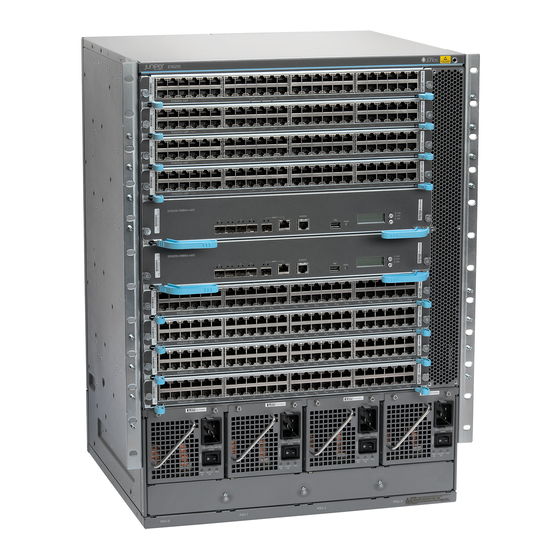
Chassis Physical Specifications, LCD Panel, and Backplane The EX6210 switch is 14 rack units (14 U) in size. Three EX6210 switches can fit in a standard 42 U rack. Each EX6210 switch is designed to optimize rack space and cabling. -
Page 25: Switch Fabric And Routing Engine Modules
ESD point The EX6210 switch can have up to two chassis-level LCD panels, one on each Switch Fabric and Routing Engine (SRE) module. The LCD panel on the master SRE module displays Routing Engine and chassis components’ alarm information for rapid problem identification. -
Page 26: Line Cards
The EX6210 switch supports line rate for each line card installed. You can install up to nine line cards in an EX6210 switch—one in each of the eight line card slots and one in the SRE module slot—in any combination of the line cards. The line cards in EX6200 switches combine a Packet Forwarding Engine and Ethernet interfaces on a single assembly. -
Page 27: Ex6210 Switch Configurations
Field-Replaceable Units in an EX6210 Switch on page 25 EX6210 Switch Configurations The EX6210 switch is available for shipping in four configurations. Table 5 on page 7 lists the hardware configurations for the switch and the components included in each shipping configuration. - Page 28 Complete Hardware Guide for EX6210 Ethernet Switches Table 5: EX6210 Switch Hardware Shipping Configurations (continued) Switch Configuration Model Number Configuration Components 96-port PoE+ system EX6210-S64-96P-A25 Chassis with backplane configuration (AC) (with One fan tray 2500 W AC power supply) One Switch Fabric and Routing Engine (SRE) module...
-
Page 29: Chassis Physical Specifications Of An Ex6210 Switch
Documentation Field-Replaceable Units in an EX6210 Switch on page 25 Chassis Physical Specifications of an EX6210 Switch The EX6210 switch chassis is a rigid sheet-metal structure that houses the other switch components. Table 6 on page 9 summarizes the physical specifications of the EX6210 switch chassis. -
Page 30: Understanding Ex6210 Switch Component And Functionality Redundancy
OUTP UT FAIL You can mount an EX6210 switch on two or four posts of a standard 19-in. rack or a standard 800-mm enclosed cabinet. Up to three EX6210 switches can be installed in a standard (42 rack unit (U)) rack provided the rack can handle their combined weight. - Page 31 Gbps of full-duplex bandwidth to each line card slot, allowing all 384 ports to operate at wire speed. Power supplies—You can install up to four AC or four DC power supplies in an EX6210 switch. Each power supply connects to the backplane of the chassis, which distributes the output power produced by the power supplies to different switch components.
-
Page 32: Routing Engine And Control Redundancy
Each SRE module contains switch fabric circuitry, Routing Engine circuitry, and switch control and management circuitry. An EX6210 switch can have one or two SRE modules. If the switch has two SRE modules, one functions as the master while the other functions as a backup. -
Page 33: Table 8: Slot Numbering For An Ex6210 Switch
Chapter 1: EX6210 Switch Overview Table 8: Slot Numbering for an EX6210 Switch Slot Label Components Accepted in Slot Additional Information Line card Line card Line card Line card SRE module or line card NOTE: Installation of an EX6200 line card in the SRE module slot is supported in Junos OS Release 12.1... -
Page 34: Slot Numbering For The Power Supply Slots
156. Slot Numbering for the Power Supply Slots Table 9 on page 14 lists the slot numbers for the power supplies in an EX6210 switch. CAUTION: Mixing different types (AC and DC or AC power supplies of different wattage) of power supplies in the same chassis is not supported. -
Page 35: Ex6210 Switch Hardware And Cli Terminology Mapping
Chassis Physical Specifications of an EX6210 Switch on page 9 Documentation EX6210 Switch Hardware and CLI Terminology Mapping This topic describes the hardware terms used in EX6210 switch documentation and the corresponding terms used in the Junos OS command-line interface (CLI). See Table 10 on page... -
Page 36: Table 10: Cli Equivalents Of Terms Used In Documentation For Ex6210
Complete Hardware Guide for EX6210 Ethernet Switches Table 10: CLI Equivalents of Terms Used in Documentation for EX6210 Switches Hardware Field (as displayed in Description Field (as Value Field (as Term Used In the CLI) displayed in the CLI) displayed in the CLI) -
Page 37: Cooling System
Chapter 1: EX6210 Switch Overview Table 10: CLI Equivalents of Terms Used in Documentation for EX6210 Switches (continued) Hardware Field (as displayed in Description Field (as Value Field (as Term Used In the CLI) displayed in the CLI) displayed in the CLI) - Page 38 Complete Hardware Guide for EX6210 Ethernet Switches Copyright © 2014, Juniper Networks, Inc.
-
Page 39: Component Descriptions
DC Power Supply in an EX6200 Switch on page 49 DC Power Supply LEDs in an EX6200 Switch on page 52 Cooling System and Airflow in an EX6210 Switch on page 54 Backplane in an EX6210 Switch on page 56... -
Page 40: Lcd Panel Modes
Complete Hardware Guide for EX6210 Ethernet Switches NOTE: The LCD menu on the backup SRE module displays the text BACKUP No menu options are displayed on the backup LCD panel. There are two navigation buttons— —to the right of the LCD panel on each... -
Page 41: Lcd Panel Menus
The LCD menu on the backup SRE module displays the text . No BACKUP menu options are displayed on the backup LCD panel. Table 11 on page 22 describes the LCD panel menu options. Copyright © 2014, Juniper Networks, Inc. -
Page 42: Table 11: Lcd Panel Menu Options For The Ex6200 Switch
Complete Hardware Guide for EX6210 Ethernet Switches Table 11: LCD Panel Menu Options for the EX6200 Switch Menu Description Idle In the Idle menu: Press to cycle through the Status LED modes, which are port status indicators: Enter ADM (enabled/disabled) - Page 43 See Configuring the LCD Panel on EX Series Switches (CLI Procedure). Related Chassis Status LEDs in an EX6200 Switch on page 24 Documentation Field-Replaceable Units in an EX6210 Switch on page 25 Connecting and Configuring an EX Series Switch (CLI Procedure) on page 192 Copyright © 2014, Juniper Networks, Inc.
-
Page 44: Chassis Status Leds In An Ex6200 Switch
Complete Hardware Guide for EX6210 Ethernet Switches Chassis Status LEDs in an EX6200 Switch Each Switch Fabric and Routing Engine (SRE) module in an EX6200 switch has three LEDs on the right of the LCD panel. The switch can have one or two SRE modules installed. -
Page 45: Field-Replaceable Units In An Ex6210 Switch
Hot-pluggable—You can remove and replace these components without powering off the switch, but the switching function is interrupted until you replace the component. Table 13 on page 25 lists the FRUs for the EX6210 switch and their types. Table 13: FRUs in an EX6210 Switch Type Power supplies Hot-insertable and hot-removable. -
Page 46: Switch Fabric And Routing Engine (Sre) Module In An Ex6200 Switch
10-gigabit SFP+ uplink ports. See Figure 8 on page You can install one or two SRE modules in an EX6200 switch. A non-redundant EX6210 switch configuration has only one SRE module. You can add a second SRE module to the configuration for Routing Engine and switch control redundancy. - Page 47 Take the SRE module offline using the CLI before pressing the reset button. See “Taking the SRE Module Offline in an EX6200 Switch” on page 215. LCD Panel—Displays status information for the switch. See “LCD Panel in an EX6200 Switch” on page Copyright © 2014, Juniper Networks, Inc.
-
Page 48: Sre Module Leds In An Ex6200 Switch
Ejector levers—Used for installing and removing the SRE module. Captive screws—Secure the SRE module in place. Related Installing an SRE Module in an EX6210 Switch on page 156 Documentation Removing an SRE Module from an EX6200 Switch on page 217... -
Page 49: Uplink Port Leds In Ex6200 Switches
Table 15 on page 30 describes the Status LED. From the Idle menu of the master SRE module LCD, use the Enter button on the LCD panel to toggle between the ADM, DPX, PoE, and SPD indicators. Copyright © 2014, Juniper Networks, Inc. -
Page 50: Management Port Leds In Ex6200 Switches
Complete Hardware Guide for EX6210 Ethernet Switches Table 15: Status LED on an Uplink Port on EX6200 Switches LCD Indicator State and Description Status LED: ADM Indicates the administrative status (enabled or disabled). The status indicators are: Green (On steadily)—Administrative status is enabled. -
Page 51: 48-Port Rj-45 Line Card In An Ex6200 Switch
See “Slot Numbering for an EX6210 Switch” on page 12. The line cards are hot-insertable and hot-removable: You can remove and replace them without powering off the switch or disrupting switch functions. -
Page 52: Line Card Components
Complete Hardware Guide for EX6210 Ethernet Switches Table 18: 48-port RJ-45 Line Card Models Model Description Junos OS Release Required EX6200-48T 48-port RJ-45 line card 11.3R2 or later Line Card Components The 48-port RJ-45 line card (see Figure 12 on page... -
Page 53: Line Card Components
See “Slot Numbering for an EX6210 Switch” on page 12. The line cards are hot-insertable and hot-removable: You can remove and replace them without powering off the switch or disrupting switch functions. -
Page 54: Line Card Models
Complete Hardware Guide for EX6210 Ethernet Switches Line Card Models Table 20 on page 34 provides the model number, the name of the line card model, and the Junos OS release in which the model was first supported. Table 20: 48-Port SFP Line Card Model... -
Page 55: Figure 16: Line Card Leds On A 48-Port Poe+ Card In An Ex6200 Switch
48-Port RJ-45 Line Card in an EX6200 Switch on page 31 Documentation 48-Port PoE+ Line Card in an EX6200 Switch on page 32 48-Port SFP Line Card in an EX6200 Switch on page 33 Copyright © 2014, Juniper Networks, Inc. -
Page 56: Line Card Model And Version Compatibility In An Ex6200 Switch
Complete Hardware Guide for EX6210 Ethernet Switches Line Card Model and Version Compatibility in an EX6200 Switch Three line cards are available for EX6200 switches. Table 22 on page 36 shows the model numbers, the names of the line cards, and the Junos OS release in which the models were first supported. -
Page 57: Table 23: Network Port Leds On Line Cards In An Ex6200 Switch-Link/Activity
Unlit—PoE is not enabled on the port. Related 48-Port RJ-45 Line Card in an EX6200 Switch on page 31 Documentation 48-Port PoE+ Line Card in an EX6200 Switch on page 32 Copyright © 2014, Juniper Networks, Inc. -
Page 58: Ac Power Supplies In An Ex6200 Switch
EX6200 switches. The switches support both 2500 W AC power supplies and 5000 W AC power supplies. Each power supply connects to the backplane in an EX6210 switch. The backplane distributes the output power produced by the power supplies to different switch components. -
Page 59: Front
Number 2 (Labeled Input 1 Input 2 NOTE: Each AC appliance Type IEC-320-C20 IEC-320-C20 inlet requires a dedicated AC power feed. Rating 16 A 16 A Enable switch Fans Internal Internal Airflow Front-to-back Front-to-back Copyright © 2014, Juniper Networks, Inc. - Page 60 Complete Hardware Guide for EX6210 Ethernet Switches Table 25: Details of the 2500 W AC and 5000 W AC Power Supplies (continued) Details 2500 AC Power Supply 5000 AC Power Supply AC power cord retainer Power supply status LEDs Input OK...
-
Page 61: Ac Power Supply Power Cord Retainer
AC appliance inlet on the faceplate. The adjustment nut holds the power cord in the correct position. For instructions on installing the power cord retainer, see “Connecting AC Power to an EX6200 Switch” on page 177. Copyright © 2014, Juniper Networks, Inc. -
Page 62: Power Supply Cover Panels
Complete Hardware Guide for EX6210 Ethernet Switches Figure 22: Power Cord Retainers for a 5000 W AC Power Supply Adjustment Retainer clip Power Supply Cover Panels All switch configurations of EX6200 switches ship with one power supply installed in the switch. -
Page 63: Power Supply Airflow
For details about different switch configurations, see “EX6210 Switch Configurations” on page 7 Table 27 on page 44 lists the N+1 power requirements of EX6210 switch configurations that use 2500 W AC and 5000 W AC power supplies. Copyright © 2014, Juniper Networks, Inc. -
Page 64: Table 27: N+1 Power Redundancy Configurations For Different Ex6210 Switch Configurations Using 2500 W Ac And 5000 W Ac Power Supplies
The calculations for the 5000 W AC power supply are based on the assumption that both power feeds are connected and active. Table 27: N+1 Power Redundancy Configurations for Different EX6210 Switch Configurations Using 2500 W AC and 5000 W AC Power Supplies... -
Page 65: N+N Redundancy Configuration Of Ac Power Supplies
Chapter 2: Component Descriptions Table 27: N+1 Power Redundancy Configurations for Different EX6210 Switch Configurations Using 2500 W AC and 5000 W AC Power Supplies (continued) 2500 W AC Power Supply 5000 W AC Power Supply Minimum Ports Minimum Ports... -
Page 66: Table 28: N+N Power Redundancy Configurations For Different Ex6210 Switch Configurations Using 2500 W Ac And 5000 W Ac Power Supplies
The calculations for the 5000 W AC power supply are based on the assumption that both power feeds are connected and active. Table 28: N+N Power Redundancy Configurations for Different EX6210 Switch Configurations Using 2500 W AC and 5000 W AC Power Supplies... -
Page 67: Ac Power Supply Leds In An Ex6200 Switch
Chapter 2: Component Descriptions Table 28: N+N Power Redundancy Configurations for Different EX6210 Switch Configurations Using 2500 W AC and 5000 W AC Power Supplies (continued) 2500 W AC Power Supply 5000 W AC Power Supply Minimum Ports Minimum Ports... -
Page 68: Figure 24: 2500 W Ac Power Supply Leds
Complete Hardware Guide for EX6210 Ethernet Switches Figure 24: 2500 W AC Power Supply LEDs AC appliance inlet Captive screws 100 -12 0V/ 200 -24 0V~ 15A 47- 63H z STA ND BY INP UT OUT PUT FAIL Handle Enable switch... -
Page 69: Dc Power Supply In An Ex6200 Switch
(left to right). PSU 0 PSU 3 “Slot Numbering for an EX6210 Switch” on page 12. All power supplies are accessible from the front of the chassis. NOTE: Grounding is required for DC-powered systems. -
Page 70: Figure 26: Dc Power Supply
Complete Hardware Guide for EX6210 Ethernet Switches WARNING: The switch is a pluggable type A equipment installed in a restricted-access location. It has a separate protective earthing terminal provided on the chassis. This separate protective earthing terminal must be permanently connected to earth ground. -
Page 71: Table 30: N+1 Power Redundancy Configurations For Different Ex6210 Switch Configurations Using 2100 W Dc Power Supplies
EX6200 switch configurations. Table 30 on page 51 lists the N+1 power requirements of an EX6210 switch configuration that use 2100 W DC power supplies. Table 30: N+1 Power Redundancy Configurations for Different EX6210 Switch Configurations Using 2100 W DC Power Supplies... -
Page 72: Dc Power Supply Leds In An Ex6200 Switch
Complete Hardware Guide for EX6210 Ethernet Switches Table 31 on page 52 lists the N+N power requirements of an EX6210 switch configuration that use 2100 W DC power supplies. Table 31: N+N Power Redundancy Configurations for Different EX6210 Switch Configurations Using 2100 W DC Power Supplies... -
Page 73: Figure 27: Dc Power Supply Leds In An Ex6200 Switch
Power supply is not supplying DC power correctly. Green On steadily—DC power output is within normal operating range. Blinking—DC output voltage is not within normal operating range. FAIL Unlit Power supply is functioning normally. On steadily—Power supply has failed. Copyright © 2014, Juniper Networks, Inc. -
Page 74: Cooling System And Airflow In An Ex6210 Switch
Documentation Cooling System and Airflow in an EX6210 Switch The cooling system in an EX6210 switch consists of a single fan tray. The fan tray is a hot-insertable and hot-removable field-replaceable unit (FRU). The fan tray contains six fans, three rows of two fans each. -
Page 75: Figure 29: Airflow Through The Ex6210 Switch Chassis
Hot air exhausts from the rear left side of the chassis. See Figure 29 on page Figure 29: Airflow Through the EX6210 Switch Chassis Air exhaust Air intake... -
Page 76: Backplane In An Ex6210 Switch
Related Field-Replaceable Units in an EX6210 Switch on page 25 Documentation Installing a Fan Tray in an EX6210 Switch on page 154 Removing a Fan Tray from an EX6210 Switch on page 213 Backplane in an EX6210 Switch The backplane is a printed circuit board that forms the back of the line card cage. The Switch Fabric and Routing Engine (SRE) modules, power supplies, and line cards plug into the backplane from the front of the chassis. -
Page 77: Component Specifications
Grounding Cable and Lug Specifications for EX6200 Switches on page 83 USB Port Specifications for an EX Series Switch The following Juniper Networks USB flash drives have been tested and are officially supported for the USB port on all EX Series switches:... -
Page 78: Console Port Connector Pinout Information For An Ex Series Switch
Complete Hardware Guide for EX6210 Ethernet Switches Related EX2200 Switches Hardware Overview Documentation Rear Panel of an EX3200 Switch Rear Panel of an EX3300 Switch Rear Panel of an EX4200 Switch EX4300 Switches Hardware Overview Front Panel of an EX4500 Switch... -
Page 79: To Db-9 Serial Port Adapter Pinout Information For An Ex Series
Table 34 on page 59 provides the pinout information for the RJ-45 to DB-9 serial port adapter. Table 34: EX Series Switches RJ-45 to DB-9 Serial Port Adapter Pinout Information RJ-45 Pin Signal DB-9 Pin Signal Copyright © 2014, Juniper Networks, Inc. -
Page 80: Management Port Connector Pinout Information For An Ex6200 Switch
Complete Hardware Guide for EX6210 Ethernet Switches Table 34: EX Series Switches RJ-45 to DB-9 Serial Port Adapter Pinout Information (continued) RJ-45 Pin Signal DB-9 Pin Signal Related Connecting an EX Series Switch to a Management Console on page 186... -
Page 81: Pluggable Transceivers Supported On Ex6200 Switches
NOTE: Use only optical transceivers and optical connectors purchased from Juniper Networks for your EX Series switches. The Gigabit Ethernet SFP and SFP+ transceivers installed in EX6200 switches support digital optical monitoring (DOM). You can view the diagnostic details for these transceivers... -
Page 82: Table 36: Optical Interface Support And Copper Interface Support For Gigabit Ethernet Sfp Transceivers In Ex6200 Switches
Complete Hardware Guide for EX6210 Ethernet Switches Table 36: Optical Interface Support and Copper Interface Support for Gigabit Ethernet SFP Transceivers in EX6200 Switches Ethernet Standard Specification Value 1000BASE-LH (or Model Number EX-SFP-1GE-LH 1000BASE-ZX) Rate 1000 Mbps Connector Type Fiber Count... - Page 83 Maximum Input Power –3 dBm Fiber Type Core/Cladding Size 9/125 µm Modal Bandwidth – Distance 10 km (6.2 miles) DOM Support Available Software Required Junos OS for EX Series switches, Release 12.1 or later Copyright © 2014, Juniper Networks, Inc.
- Page 84 Complete Hardware Guide for EX6210 Ethernet Switches Table 36: Optical Interface Support and Copper Interface Support for Gigabit Ethernet SFP Transceivers in EX6200 Switches (continued) Ethernet Standard Specification Value 1000BASE-SX Model Number EX-SFP-1GE-SX Rate 1000 Mbps Connector Type Fiber Count...
- Page 85 Maximum Input Power – Fiber Type Copper Core/Cladding Size – Modal Bandwidth – Distance 100 m (328 ft) DOM Support Not available Software Required Junos OS for EX Series switches, Release 12.1 or later Copyright © 2014, Juniper Networks, Inc.
- Page 86 Complete Hardware Guide for EX6210 Ethernet Switches Table 36: Optical Interface Support and Copper Interface Support for Gigabit Ethernet SFP Transceivers in EX6200 Switches (continued) Ethernet Standard Specification Value 1000BASE-LX Model Number EX-SFP-1GE-LX40K Rate 1000 Mbps Connector Type Fiber Count...
-
Page 87: Table 37: Optical Interface Support For Sfp+ Transceivers In Ex6200
Modal Bandwidth 1500 MHz/km MHz/km MHz/km Distance 10 m 30 m 100 m (32.8 ft) (98.4 ft) (328 ft) DOM Support Available Software Required Junos OS for EX Series switches, Release 11.3R2 or later Copyright © 2014, Juniper Networks, Inc. - Page 88 Complete Hardware Guide for EX6210 Ethernet Switches Table 37: Optical Interface Support for SFP+ Transceivers in EX6200 Switches (continued) Ethernet Standard Specification Value 10GBASE-SR Model Number EX-SFP-10GE-SR Rate 10 Gbps Connector Type Transmitter Wavelength 850 nm Minimum Launch Power –7.3 dBm Maximum Launch Power –1 dBm...
- Page 89 FDDI/OM1 Modal Bandwidth MHz/km MHz/km MHz/km Distance 220 m 220 m 220 m (722 ft) (722 ft) (722 ft) DOM Support Available Software Required Junos OS for EX Series switches, Release 11.3R2 or later Copyright © 2014, Juniper Networks, Inc.
- Page 90 Complete Hardware Guide for EX6210 Ethernet Switches Table 37: Optical Interface Support for SFP+ Transceivers in EX6200 Switches (continued) Ethernet Standard Specification Value 10GBASE-LR Model Number EX-SFP-10GE-LR Rate 10 Gbps Connector Type Transmitter Wavelength 1310 nm Minimum Launch Power –8.2 dBm Maximum Launch Power 0.5 dBm...
- Page 91 Maximum Input Power –1 dBm Fiber Type Core/Cladding Size 9/125 µm Modal Bandwidth – Distance 40 km (24.8 miles) DOM Support Available Software Required Junos OS for EX Series switches, Release 11.3R2 or later Copyright © 2014, Juniper Networks, Inc.
-
Page 92: Table 38: Optical Interface Support For Ex6200-48F Line Cards
Complete Hardware Guide for EX6210 Ethernet Switches Table 38: Optical Interface Support for EX6200-48F Line cards Ethernet Standard Specification Value 1000BASE-BX-U Model Number EX-SFP-GE10KT13R14 Rate 1000 Mbps Connector Type Fiber Count Single Transmitter Wavelength 1310 nm Receiver Wavelength 1490 nm Minimum Launch Power –9 dBm... - Page 93 Maximum Input Power –3 dBm Fiber Type Core/Cladding Size 9/125 µm Modal Bandwidth – Distance 10 km (6.2 miles) DOM Support Available Software Required Junos OS for EX Series switches, Release 13.2X50-D10 or later Copyright © 2014, Juniper Networks, Inc.
- Page 94 Complete Hardware Guide for EX6210 Ethernet Switches Table 38: Optical Interface Support for EX6200-48F Line cards (continued) Ethernet Standard Specification Value 1000BASE-BX-U Model Number EX-SFP-GE10KT13R15 Rate 1000 Mbps Connector Type Fiber Count Single Transmitter Wavelength 1310 nm Receiver Wavelength 1550 nm Minimum Launch Power –9 dBm...
- Page 95 Maximum Input Power –3 dBm Fiber Type Core/Cladding Size 9/125 µm Modal Bandwidth – Distance 10 km (6.2 miles) DOM Support Available Software Required Junos OS for EX Series switches, Release 13.2X50-D10 or later Copyright © 2014, Juniper Networks, Inc.
- Page 96 Complete Hardware Guide for EX6210 Ethernet Switches Table 38: Optical Interface Support for EX6200-48F Line cards (continued) Ethernet Standard Specification Value 1000BASE-BX-U Model Number EX-SFP-GE40KT13R15 Rate 1000 Mbps Connector Type Fiber Count Single Transmitter Wavelength 1310 nm Receiver Wavelength 1550 nm Minimum Launch Power –6.5 dBm...
- Page 97 Maximum Input Power –3 dBm Fiber Type Core/Cladding Size 9/125 µm Modal Bandwidth – Distance 40 km (24.8 miles) DOM Support Available Software Required Junos OS for EX Series switches, Release 13.2X50-D10 or later Copyright © 2014, Juniper Networks, Inc.
- Page 98 Complete Hardware Guide for EX6210 Ethernet Switches Table 38: Optical Interface Support for EX6200-48F Line cards (continued) Ethernet Standard Specification Value 100BASE-BX-U Model Number EX-SFP-FE20KT13R15 Rate 100 Mbps Connector Type Fiber Count Single Transmitter Wavelength 1310 nm Receiver Wavelength 1550 nm Minimum Launch Power –14 dBm...
-
Page 99: Sfp+ Direct Attach Cables For Ex Series Switches
Twinax cables, are suitable for in-rack connections between servers and switches. They are suitable for short distances of up to 23 ft (7 m), making them ideal for highly cost-effective networking connectivity within a rack and between adjacent racks. Copyright © 2014, Juniper Networks, Inc. -
Page 100: Cable Specifications
(EX8200-40XS) Junos OS Release 11.1 NOTE: We recommend that you use only Juniper Networks SFP+ direct attach cables with your EX Series switches. The cables are hot-removable and hot-insertable: You can remove and replace them without powering off the switch or disrupting switch functions. A cable comprises a low-voltage cable assembly that connects directly into two SFP+ ports, one at each end of the cable. -
Page 101: Table 40: Sfp+ Direct Attach Cable Specifications
Cable type Twinax Wire AWG 30 AWG Minimum cable bend radius 1 in. (2.54 cm) Cable characteristic impedance 100 ohms Crosstalk between pairs 2% maximum Time delay 1.31 nsec/ft Length 3.3 ft (1 m) Copyright © 2014, Juniper Networks, Inc. - Page 102 Complete Hardware Guide for EX6210 Ethernet Switches Table 40: SFP+ Direct Attach Cable Specifications (continued) Model Number Specification Value EX-SFP-10GE-DAC-3M Rate 10-Gbps full-duplex serial transmission Connector type SFP+ passive Twinax cable assembly Supply voltage 3.3 V Power consumption (per end) 0.57 W...
-
Page 103: Standards Supported By These Cables
(EMI) requirements. To ground an EX6200 switch, connect a grounding cable to earth ground on one side, attach the other side to the cable lug, and then attach the cable lug to the chassis grounding point. Copyright © 2014, Juniper Networks, Inc. -
Page 104: Figure 30: Location Of Protective Earthing Terminal On An Ex6210 Switch
A pair of threaded inserts (PEM nuts) is provided on the rear towards the bottom of the EX6210 chassis for connecting the switch to earth ground. The grounding points fit UNC ¼-20 screws. The grounding points are spaced at 0.625 in. (15.86 mm). See Figure 30 on page 84 for the location of the protective earthing terminal. - Page 105 NOTE: A grounding lug (Panduit LCD2-14A-L), two ¼-20 x 0.5 screws and two flat washers are shipped with the EX6210 chassis. The grounding cable that you provide for the switch must be the same gage as the power source cables or as permitted by the local code.
- Page 106 Complete Hardware Guide for EX6210 Ethernet Switches Copyright © 2014, Juniper Networks, Inc.
-
Page 107: Planning For Switch Installation
PART 2 Planning for Switch Installation Site Preparation on page 89 Rack and Cabinet Requirements on page 97 Cable Requirements on page 103 Planning Power Requirements on page 107 Copyright © 2014, Juniper Networks, Inc. - Page 108 Complete Hardware Guide for EX6210 Ethernet Switches Copyright © 2014, Juniper Networks, Inc.
-
Page 109: Site Preparation
Verify that environmental factors such as “Environmental Requirements and temperature and humidity do not exceed switch Specifications for EX Series Switches” tolerances. on page 93 Power Measure distance between external power sources and switch installation site. Copyright © 2014, Juniper Networks, Inc. - Page 110 Related General Safety Guidelines and Warnings on page 259 Documentation Mounting an EX6210 Switch on a Rack or Cabinet on page 138 Copyright © 2014, Juniper Networks, Inc.
-
Page 111: General Site Guidelines
EX Series Redundant Power System (RPS), and the XRE200 External Routing Engine. This topic also applies to hardware devices in the QFX Series. Table 42 on page 92 describes the factors you must consider while planning the electrical wiring at your site. Copyright © 2014, Juniper Networks, Inc. -
Page 112: Table 42: Site Electrical Wiring Guidelines
Complete Hardware Guide for EX6210 Ethernet Switches WARNING: It is particularly important to provide a properly grounded and shielded environment and to use electrical surge-suppression devices. Table 42: Site Electrical Wiring Guidelines Site Wiring Factor Guidelines Signaling limitations If your site experiences any of the following problems, consult experts in electrical surge suppression and shielding: Improperly installed wires cause radio frequency interference (RFI). -
Page 113: Environmental Requirements And Specifications For Ex Series Switches
Table 43 on page 94 provides the required environmental conditions for normal switch operation. Copyright © 2014, Juniper Networks, Inc. -
Page 114: Table 43: Ex Series Switch Environmental Tolerances
Complete Hardware Guide for EX6210 Ethernet Switches Table 43: EX Series Switch Environmental Tolerances Environment Tolerance Switch or device Altitude Relative Humidity Temperature Seismic EX2200-C No performance Normal operation ensured Normal operation ensured in the Complies with Zone 4 degradation up to in relative humidity range temperature range 32°... - Page 115 41° F through earthquake 10,000 feet (3048 of 10% through 85% 104° F (5° C through 40° C) requirements as per meters) (noncondensing) GR-63, Issue 3. Copyright © 2014, Juniper Networks, Inc.
- Page 116 Clearance Requirements for Airflow and Hardware Maintenance for EX4500 Switches Clearance Requirements for Airflow and Hardware Maintenance for EX4550 Switches Clearance Requirements for Airflow and Hardware Maintenance for an EX6210 Switch on page 101 Clearance Requirements for Airflow and Hardware Maintenance for an EX8208 Switch...
-
Page 117: Rack And Cabinet Requirements
Association ( http://www.eia.org You can stack three EX6210 switches in a two-post or four-post rack that has at least 42 U; if you install the optional power cord tray, a minimum of 45 U are required. In all cases, the rack must meet the strength requirements to support the weight. -
Page 118: Figure 31: Installing An Ex6210 Switch In A Two-Post Rack
The rack must be strong enough to support the weight of the fully loaded switch. A fully loaded EX6210 switch weighs up to 215 lb (98 kg). If you stack three fully loaded EX6210 switches in one rack, that rack must support up to 645 lb (293 kg). -
Page 119: Cabinet Requirements And Specifications For An Ex6210 Switch
Chassis Physical Specifications of an EX6210 Switch on page 9 Cabinet Requirements and Specifications for an EX6210 Switch You can mount an EX6210 switch on a cabinet that contains a 19-in. rack as defined in Cabinets, Racks, Panels, and Associated Equipment (document number EIA-310-D) published by the Electronics Industry Association ( http://www.eia.org... -
Page 120: Clearance Requirements For Airflow And Hardware Maintenance For An Ex6210
Complete Hardware Guide for EX6210 Ethernet Switches Table 45: Cabinet Requirements and Specifications for an EX6210 Switch Cabinet Requirement Guidelines for the EX6210 Switch Cabinet size and clearance The minimum cabinet size must be able to accommodate the maximum external dimensions if the switch. The outer edges of the mounting brackets extend the width of the chassis to 19 in. -
Page 121: Figure 33: Airflow Through The Ex6210 Switch Chassis
Chassis Physical Specifications of an EX6210 Switch on page 9 Clearance Requirements for Airflow and Hardware Maintenance for an EX6210 Switch When planning the site for installing an EX6210 switch, you must allow sufficient clearance around the switch. For the cooling system to function properly, the airflow around the chassis must be unrestricted. -
Page 122: Figure 34: Clearance Requirements For Airflow And Hardware Maintenance For
Front-mounting bracket Related Cabinet Requirements and Specifications for an EX6210 Switch on page 99 Documentation Rack Requirements for an EX6210 Switch on page 97 Rack-Mounting and Cabinet-Mounting Warnings on page 274 Cooling System and Airflow in an EX6210 Switch on page 54... -
Page 123: Cable Requirements
RJ-45 (10/100/1000) 1000Base-T connectors operation Related Connecting an EX Series Switch to a Management Console on page 186 Documentation Connecting an EX Series Switch to a Network for Out-of-Band Management on page 188 Copyright © 2014, Juniper Networks, Inc. -
Page 124: Understanding Ex Series Switches Fiber-Optic Cable Signal Loss, Attenuation
Complete Hardware Guide for EX6210 Ethernet Switches Understanding EX Series Switches Fiber-Optic Cable Signal Loss, Attenuation, and Dispersion To determine the power budget and power margin needed for fiber-optic connections, you need to understand how signal loss, attenuation, and dispersion affect transmission. - Page 125 (including those from dispersion), and a safety margin for unexpected losses. Related Calculating the EX Series Switch Fiber-Optic Cable Power Budget on page 122 Documentation Calculating the EX Series Switch Fiber-Optic Cable Power Margin on page 122 Copyright © 2014, Juniper Networks, Inc.
- Page 126 Complete Hardware Guide for EX6210 Ethernet Switches Copyright © 2014, Juniper Networks, Inc.
-
Page 127: Planning Power Requirements
Power Requirements for EX6210 Switch Components on page 109 AC Power Cord Specifications for an EX6200 Switch on page 109 Calculating Power Requirements for an EX6210 Switch on page 113 Calculating the EX Series Switch Fiber-Optic Cable Power Budget on page 122... -
Page 128: Dc Power Specifications For Ex6200 Switches
Complete Hardware Guide for EX6210 Ethernet Switches Table 47: Power Specifications for the AC Power Supplies Used in an EX6200 Switch (continued) Item Specifications AC output power 2500 W AC power supply: Low-voltage line—1250 W High-voltage line—2500 W 5000 W AC power supply: Both power feeds connected and active: Low-voltage line—2500 W... -
Page 129: Power Requirements For Ex6210 Switch Components
Documentation DC Power Supply in an EX6200 Switch on page 49 Calculating Power Requirements for an EX6210 Switch on page 113 AC Power Cord Specifications for an EX6200 Switch Each AC appliance inlet on the AC power supply requires a dedicated AC power feed. -
Page 130: Table 50: Ac Power Cord Specifications For An Ex6200 Switch
Complete Hardware Guide for EX6210 Ethernet Switches Each detachable AC power cord is 2.5 meters (approximately 8 feet) long. The appliance coupler at the female end of the cord inserts into the AC appliance inlet on the faceplate of the AC power supply. The coupler type is C19 as described by the International Electrotechnical Commission (IEC) standard 60320. - Page 131 125 VAC, 20 A, 50 Hz NEMA 5–20 Type N5/20 CBL-EX-PWR-C19-US20 South Africa 250 VAC, 16 A, 50 Hz SABS 164/1 Type ZA/3 CBL-EX-PWR-C19-SA Switzerland 250 VAC, 16 A, 50 Hz SEV 5934-2 Type 23G CBL-EX-PWR-C19-SZ No graphic available Copyright © 2014, Juniper Networks, Inc.
- Page 132 Complete Hardware Guide for EX6210 Ethernet Switches Table 50: AC Power Cord Specifications for an EX6200 Switch (continued) Electrical Country/Region Specifications Plug Standards Juniper Model Number Graphic Taiwan 250 VAC, 16 A, 50 Hz NEMA L6–20 Type NEMA CBL-EX-PWR-C19-TW Locking...
-
Page 133: Calculating Power Requirements For An Ex6210 Switch
Table 51 on page 113 lists the maximum power requirements of the switch components of an EX6210 switch under typical voltage conditions. The numbers in this table are used for various calculations in this topic. Table 51: EX6210 Switch Component Power Requirements... - Page 134 Complete Hardware Guide for EX6210 Ethernet Switches Table 51: EX6210 Switch Component Power Requirements (continued) Components Maximum Power Requirements (Watts) 48-port PoE+ line card (EX6200-48P) Maximum base power requirement: 220 W Maximum PoE+ Power Requirement = (Maximum Number of Ports on the Line Card )
-
Page 135: Calculating The Chassis Base Power Budget For Your Ex6210 Switch
Chapter 7: Planning Power Requirements Calculating the Chassis Base Power Budget for Your EX6210 Switch The chassis base power budget for an EX6210 switch is the sum of the maximum power requirements of the fan tray and two SRE modules. See... - Page 136 Complete Hardware Guide for EX6210 Ethernet Switches Table 52: Calculating the Maximum System Power Required for Your EX6210 Switch Configuration (continued) EX6210 switch EX6210 switch with two 48-port with two 48-port EX6210 switch PoE+ line cards, SFP line cards, with two 48-port...
-
Page 137: Calculating The Number Of Power Supplies Required For Your Ex6210 Switch Configuration
N+1. You can optionally configure power management to manage the power supplies for N+N redundancy. See Understanding Power Management on EX Series Switches. To calculate the number of power supplies required for your EX6210 switch, follow the instructions in Table 53 on page 117. - Page 138 Complete Hardware Guide for EX6210 Ethernet Switches Table 53: Calculating the Number of Power Supplies Required for Your EX6210 Switch Configuration (continued) EX6210 switch EX6210 switch with two 48-port with two 48-port EX6210 switch PoE+ line cards, SFP line cards,...
-
Page 139: Configuration
Understanding Power Management on EX Series Switches. Calculating System Thermal Output for Your EX6210 Switch Configuration To calculate the system thermal output of an EX6210 switch, follow the instructions in Table 54 on page 120. -
Page 140: Table 54: Calculating System Thermal Output For Your Ex6210 Switch
Complete Hardware Guide for EX6210 Ethernet Switches Table 54: Calculating System Thermal Output for Your EX6210 Switch Configuration EX6210 switch EX6210 switch with two 48-port with two 48-port EX6210 switch PoE+ line cards, SFP line cards, with two 48-port 2500 W AC power... - Page 141 Chapter 7: Planning Power Requirements Table 54: Calculating System Thermal Output for Your EX6210 Switch Configuration (continued) EX6210 switch EX6210 switch with two 48-port with two 48-port EX6210 switch PoE+ line cards, SFP line cards, with two 48-port 2500 W AC power...
-
Page 142: Calculating The Ex Series Switch Fiber-Optic Cable Power Budget
Complete Hardware Guide for EX6210 Ethernet Switches Calculating the EX Series Switch Fiber-Optic Cable Power Budget Calculate the link's power budget when planning fiber-optic cable layout and distances to ensure that fiber-optic connections have sufficient power for correct operation. The power budget is the maximum amount of power the link can transmit. -
Page 143: Table 55: Estimated Values For Factors Causing Link Loss
(13 dBm) – (0.5 dBm [HOL]) – ((5) * (0.5 dBm)) – ((2) * (0.5 dBm)) – ((2 km) * (1.0 dBm/km)) – (1 dB [CRM]) = P 13 dBm – 0.5 dBm – 2.5 dBm – 1 dBm – 2 dBm – 1 dBm = P Copyright © 2014, Juniper Networks, Inc. - Page 144 Complete Hardware Guide for EX6210 Ethernet Switches 13 dBm – 0.5 dBm – 2.5 dBm – 1 dBm – 2 dBm – 1 dBm = P = 6 dBm The calculated power margin is greater than zero, indicating that the link has sufficient power for transmission.
-
Page 145: Installing And Connecting The Switch And Switch Components
PART 3 Installing and Connecting the Switch and Switch Components Installing the Switch on page 127 Installing Switch Components on page 149 Connecting the Switch on page 171 Performing Initial Configuration on page 191 Copyright © 2014, Juniper Networks, Inc. - Page 146 Complete Hardware Guide for EX6210 Ethernet Switches Copyright © 2014, Juniper Networks, Inc.
-
Page 147: Installing The Switch
Mounting an EX6210 Switch on a Rack or Cabinet on page 138 Mounting an EX6210 Switch on a Rack or Cabinet Using a Mechanical Lift on page 141 Mounting an EX6210 Switch on a Rack or Cabinet Without Using a Mechanical... -
Page 148: Unpacking An Ex6200 Switch
The switch chassis is bolted to the pallet base. The EX6210 chassis ships with one Switch Fabric and Routing Engine (SRE) module, fan tray, an AC or DC power supply, and two line cards for the configuration you ordered already installed. -
Page 149: Figure 35: Pallet Fastener
Verify that your order includes all appropriate parts. See “Parts Inventory (Packing List) for an EX6210 Switch” on page 130 Store the brackets and bolts inside the accessory box. Save the shipping box, pallet, and packing materials in case you need to move or ship the switch at a later time. -
Page 150: Parts Inventory (Packing List) For An Ex6210 Switch
Pallet fasteners (4) Related Mounting an EX6210 Switch on a Rack or Cabinet on page 138 Documentation Parts Inventory (Packing List) for an EX6210 Switch Check the parts you receive in the switch shipping crate against the items on the packing list or customer information sheet. -
Page 151: Switch
Chapter 8: Installing the Switch If any part on the packing list is missing, contact your customer service representative or contact Juniper customer care from within the U.S. or Canada by telephone at 1–800–638–8296. For international-dial or direct-dial options in countries without toll-free numbers, see http://www.juniper.net/support/requesting-support.html... -
Page 152: Table 57: Accessory Box Parts List
Complete Hardware Guide for EX6210 Ethernet Switches Table 56: Parts List for Different EX6210 Switch Configurations (continued) Component Shipping Configuration Quantity Power supply blank shelf For all systems that ship with 2500 W AC or 2100 W DC power supplies:... - Page 153 2 rear adjustable mounting brackets. These brackets are labeled “REAR” on the side of the bracket that faces the interior of the rack, near the holes for attaching the bracket Copyright © 2014, Juniper Networks, Inc.
- Page 154 “Rack Requirements for an EX6210 Switch” on page 97, and “Cabinet Requirements and Specifications for an EX6210 Switch” on page Position the left front adjustable mounting bracket at the desired position in the left side of the rack and line up its front screw holes with the holes in the rack. Use 4 mounting screws appropriate for your rack to attach the left front bracket to the rack.
-
Page 155: Figure 37: Adjustable Mounting Brackets For Four-Post Rack Installation
Figure 37 on page 135): Insert 6 of the screws provided with the mounting brackets into the overlapping bracket holes. Tighten the screws fully (to 12–16 in.-lb torque) using a number 2 Phillips screwdriver. Copyright © 2014, Juniper Networks, Inc. -
Page 156: Installing The Power Cord Tray In A Rack Or Cabinet For An Ex6200 Switch
The power cord tray uses 1 U of rack space (the remainder of this topic uses “rack” to mean “rack or cabinet” ) , so the total space occupied by an EX6210 switch chassis and power cord tray is 15 U. -
Page 157: Figure 39: Installing The Power Cord Tray In A Four-Post Rack
“Rack Requirements for an EX6210 Switch” on page 97, and “Cabinet Requirements and Specifications for an EX6210 Switch” on page Position the power cord tray in the rack space immediately below the position in which you want to install the switch or where the switch is installed (see Figure 39 on page 137). -
Page 158: Mounting An Ex6210 Switch On A Rack Or Cabinet
Front-mounting bracket Related Mounting an EX6210 Switch on a Rack or Cabinet on page 138 Documentation Mounting an EX6210 Switch on a Rack or Cabinet The EX6210 switch ships installed with front-mounting brackets on the chassis for mounting the switch on a 19-in. rack or cabinet. You can purchase the optional adjustable mounting brackets to support the switch in a four-post rack and the optional power cord tray to manage the power supply cords. - Page 159 Place the rack or cabinet in its permanent location, allowing adequate clearance for airflow and maintenance, and secure it to the building structure. See “Clearance Requirements for Airflow and Hardware Maintenance for an EX6210 Switch” on page 101 for detailed information. Read “General Safety Guidelines and Warnings”...
-
Page 160: Figure 41: Installing An Ex6210 Switch In A Two-Post Rack
Insert 24 mounting screws appropriate for your rack (not provided) into the aligned holes. Use the appropriate Phillips (+) screwdriver to tighten the screws to the rack or cabinet rail. Figure 41: Installing an EX6210 Switch in a Two-Post Rack Two-post rack Front-mounting... -
Page 161: Mounting An Ex6210 Switch On A Rack Or Cabinet Using A Mechanical Lift
Chapter 8: Installing the Switch Cabinet Requirements and Specifications for an EX6210 Switch on page 99 Mounting an EX6210 Switch on a Rack or Cabinet Using a Mechanical Lift You can use a mechanical lift to install the EX6210 switch. -
Page 162: Figure 43: Installing The Ex6210 Switch Chassis Using A Mechanical Lift
Load the switch onto the lift, making sure it rests securely on the lift platform. Figure 43: Installing the EX6210 Switch Chassis Using a Mechanical Lift Using the lift, position the switch in front of the rack or cabinet, centering it in front of the rails of the rack or cabinet or the adjustable mounting brackets and/or power cord tray, if installed. - Page 163 Connecting and Configuring an EX Series Switch (CLI Procedure) on page 192 Mounting an EX6210 Switch on a Rack or Cabinet Without Using a Mechanical Lift If you cannot use a mechanical lift to install the switch, you can install it manually.
- Page 164 Removing an SRE Module from an EX6200 Switch on page 217 Removing a Line Card from an EX6200 Switch on page 219 Removing a Fan Tray from an EX6210 Switch on page 213 Removing an AC Power Supply from an EX6200 Switch on page 209...
-
Page 165: Lift
Do not twist your body as you lift. Balance the load evenly and be sure that your footing is firm. Figure 44: Lifting an EX6210 Switch Chassis Without Using a Mechanical Lift Push the bottom of the chassis so that the front-mounting brackets are flush with the front of the rack. -
Page 166: Figure 45: Installing An Ex6210 Switch In A Two-Post Rack
After you install the mounting screws and securely bolt the chassis to the rack, reinstall the components in the chassis. See: Installing an SRE Module in an EX6210 Switch on page 156 Installing a Line Card in an EX6200 Switch on page 160 Installing a Fan Tray in an EX6210 Switch on page 154 Copyright ©... - Page 167 Installing a DC Power Supply in an EX6200 Switch on page 153 Related Powering On an EX6200 Switch on page 184 Documentation Connecting and Configuring an EX Series Switch (CLI Procedure) on page 192 Copyright © 2014, Juniper Networks, Inc.
- Page 168 Complete Hardware Guide for EX6210 Ethernet Switches Copyright © 2014, Juniper Networks, Inc.
-
Page 169: Installing Switch Components
Installing the Air Filter in an EX6210 Switch on page 167 Installing and Removing EX6210 Switch Hardware Components The EX6210 switch chassis is a rigid sheet-metal structure that houses the hardware components. The field-replaceable units (FRUs) in an EX6210 switch are:... -
Page 170: Installing An Ac Power Supply In An Ex6200 Switch
See these topics for instructions for installing and removing components: Installing an SRE Module in an EX6210 Switch on page 156 Removing an SRE Module from an EX6200 Switch on page 217... -
Page 171: Figure 47: Power Supply Blank Shelf On An Ex6200 Switch With 2500 W Ac
Standby position. Using both hands, place the power supply in the power supply slot on the front of the switch. Slide the power supply straight into the chassis until the power supply is fully Copyright © 2014, Juniper Networks, Inc. -
Page 172: Figure 48: Installing A 2500 W Ac Power Supply In An Ex6200 Switch
Complete Hardware Guide for EX6210 Ethernet Switches seated in the slot. Ensure the power supply faceplate is flush with any adjacent power supply faceplates or power supply cover panels. NOTE: Power supplies can be installed in any slot. You need not install the power supplies in serial order. -
Page 173: Installing A Dc Power Supply In An Ex6200 Switch
All DC power supplies install in the front of the chassis in the slots provided at the bottom. See “Slot Numbering for an EX6210 Switch” on page Before you install a DC power supply in the switch: Ensure you understand how to prevent ESD damage. See “Prevention of Electrostatic... -
Page 174: Installing A Fan Tray In An Ex6210 Switch
DC Power Supply in an EX6200 Switch on page 49 Installing a Fan Tray in an EX6210 Switch An EX6210 switch has a single, field-replaceable fan tray. The fan tray is a hot-insertable and hot-removable field-replaceable unit (FRU); you can remove and replace the fan tray while the switch is running without turning off power to the switch or disrupting switching functions. - Page 175 Chapter 9: Installing Switch Components removing the fan tray, at room temperature, to prevent the chassis from overheating . To install a fan tray in an EX6210 switch (see Figure 51 on page 156): Attach the electrostatic discharge (ESD) grounding strap to your bare wrist, and connect the strap to the ESD point on the chassis.
-
Page 176: Installing An Sre Module In An Ex6210 Switch
Installing an SRE Module in an EX6210 Switch You can install either one or two Switch Fabric and Routing Engine (SRE) modules in an EX6210 switch. The SRE modules install horizontally in the front of the chassis in the slots labeled NOTE: We recommend that you install two SRE modules for redundancy. -
Page 177: Figure 52: Open And Closed Positions Of The Sre Module Ejector Lever
Chapter 9: Installing Switch Components Before you begin installing an SRE module in an EX6210 switch: Ensure you understand how to prevent ESD damage. See “Prevention of Electrostatic Discharge Damage” on page 288. Inspect the connector edge of the SRE module for physical damage. Installing a damaged SRE module may damage the switch. -
Page 178: Figure 53: Sre Module Cover Panel
Complete Hardware Guide for EX6210 Ethernet Switches Figure 53: SRE Module Cover Panel Line card cover panels SRE module filler panel SRE module cover panel Line card cover panel Carefully align the sides of the SRE module with the guides inside the chassis. -
Page 179: Unpacking An Ex6200 Line Card
Chapter 9: Installing Switch Components Figure 54: Installing an SRE Module in an EX6210 Switch Related Removing an SRE Module from an EX6200 Switch on page 217 Documentation Switch Fabric and Routing Engine (SRE) Module in an EX6200 Switch on page 26... -
Page 180: Installing A Line Card In An Ex6200 Switch
Switch Fabric and Routing Engine (SRE) module slots on the front of the switch chassis. See “Slot Numbering for an EX6210 Switch” on page 12. The line cards are hot-insertable and hot-removable: You can remove and replace them without powering off the switch or disrupting switch functions. - Page 181 Ensure the switch has sufficient power to power the line card while maintaining its N+1 or N+N power redundancy. To determine the power requirements of the line card, see “Power Requirements for EX6210 Switch Components” on page 109. To determine whether the switch has enough power available for the line card, use command.
-
Page 182: Figure 56: Sre Module Cover Panel
Complete Hardware Guide for EX6210 Ethernet Switches Figure 56: SRE Module Cover Panel Line card cover panels SRE module filler panel SRE module cover panel Line card cover panel CAUTION: Do not lift the line card by holding the ejector levers on the faceplate or the edge connectors. -
Page 183: Figure 58: Installing A Line Card
Verify that the SRE module filler panel is installed in slots 4 or 5, if a line card is installed in either of these slots, to ensure proper airflow in the chassis. You can verify that the line card is functioning correctly by issuing the show chassis fpc commands. show chassis fpc pic-status Copyright © 2014, Juniper Networks, Inc. -
Page 184: Installing A Transceiver In An Ex Series Switch
Complete Hardware Guide for EX6210 Ethernet Switches NOTE: If you have a Juniper J-Care service contract, register any addition, change, or upgrade of hardware components at https://www.juniper.net/customers/csc/management/updateinstallbase.jsp Failure to do so can result in significant delays if you need replacement parts. - Page 185 Remove the rubber safety cap when you are ready to connect the cable to the transceiver. WARNING: Do not look directly into a fiber-optic transceiver or into the ends of fiber-optic cables. Fiber-optic transceivers and fiber-optic cables connected to transceivers emit laser light that can damage your eyes. Copyright © 2014, Juniper Networks, Inc.
-
Page 186: Connecting A Fiber-Optic Cable To An Ex Series Switch
Complete Hardware Guide for EX6210 Ethernet Switches Figure 59: Installing a Transceiver in an EX Series Switch 1— Ejector lever Related Removing a Transceiver from an EX Series Switch on page 223 Documentation Connecting a Fiber-Optic Cable to an EX Series Switch on page 166... -
Page 187: Installing The Air Filter In An Ex6210 Switch
Pluggable Transceivers Supported on EX Series Switches Installing the Air Filter in an EX6210 Switch You can install an optional air filter on your EX6210 switch. The air filter does not ship with the chassis; you must order it separately. -
Page 188: Figure 61: Installing A Air Filter In An Ex6210 Switch
INPU T OUTP UT FAIL STAN D BY INPU T OUTP UT FAIL STAN D BY INPU T OUTP UT FAIL Related Removing the Air Filter from an EX6210 Switch on page 226 Documentation Copyright © 2014, Juniper Networks, Inc. - Page 189 Chapter 9: Installing Switch Components Maintaining the Air Filter in an EX6200 Switch on page 236 Copyright © 2014, Juniper Networks, Inc.
- Page 190 Complete Hardware Guide for EX6210 Ethernet Switches Copyright © 2014, Juniper Networks, Inc.
-
Page 191: Connecting The Switch
Parts and Tools Required for Connecting an EX Series Switch to Earth Ground on page 172 Special Instructions to Follow Before Connecting Earth Ground to a Switch on page 174 Connecting Earth Ground to an EX Series Switch on page 176 Copyright © 2014, Juniper Networks, Inc. -
Page 192: Parts And Tools Required For Connecting An Ex Series Switch To Earth Ground
Complete Hardware Guide for EX6210 Ethernet Switches Parts and Tools Required for Connecting an EX Series Switch to Earth Ground Table 58 on page 172 lists the earthing terminal location, grounding cable requirements, grounding lug specifications, screws and washers required, and the screwdriver needed for connecting a switch to earth ground. - Page 193 Two ¼-20 Phillips (+) chassis minimum 60°C wire, LCD2-14A-Q or x 0.5 in. screws number 2 or as permitted by equivalent with #¼” the local code —provided split-washer —provided Two #¼” flat washers— provided Copyright © 2014, Juniper Networks, Inc.
-
Page 194: Switch
Special Instructions EX3200 NOTE: Some early variants of EX3200 switches for which the Juniper Networks model number on the label next to the protective earthing terminal is from 750-021xxx through 750-030xxx require 10-24x.25 in. screws. Copyright © 2014, Juniper Networks, Inc. -
Page 195: Figure 62: Connecting The Grounding Lug To A Switch Mounted On Four Posts Of
Special Instructions EX4200 NOTE: Some early variants of EX4200 switches for which the Juniper Networks model number on the label next to the protective earthing terminal is from 750-021xxx through 750-030xxx require 10-24x.25 in. screws. NOTE: The protective earthing terminal on an EX4200 switch mounted on four posts of a rack is accessible through the slot on the left rear bracket only if the rack is 27.5 in. -
Page 196: Connecting Earth Ground To An Ex Series Switch
Complete Hardware Guide for EX6210 Ethernet Switches Connecting Earth Ground to an EX Series Switch To connect earth ground to a switch: Connect one end of the grounding cable to a proper earth ground, such as the rack in which the switch is mounted. -
Page 197: Connecting Ac Power To An Ex6200 Switch
Before you begin to connect power to the switch: Ensure you understand how to prevent ESD damage. See “Prevention of Electrostatic Discharge Damage” on page 288. Ensure that you have connected the switch chassis to earth ground. Copyright © 2014, Juniper Networks, Inc. - Page 198 Complete Hardware Guide for EX6210 Ethernet Switches NOTE: Grounding is required for DC systems and recommended for AC systems. An AC-powered switch gets additional grounding when you plug the power supply in the switch into a grounded AC power outlet by using the AC power cord appropriate for your geographical location.
-
Page 199: Figure 64: Power Cord Retainer In A 2500 W Ac Power Supply
5000 W AC power supply. If the AC power source outlet has a power switch, set it to the OFF (0) position. Insert the power cord plug into an AC power source outlet. Copyright © 2014, Juniper Networks, Inc. -
Page 200: Connecting Dc Power To An Ex6200 Switch
Complete Hardware Guide for EX6210 Ethernet Switches Repeat Steps if you are connecting a power cord to the second appliance inlet on the 5000 W AC power supply. If the AC power source outlet has a power switch, set it to the ON (|) position. - Page 201 Install the power supply in the chassis. See “Installing a DC Power Supply in an EX6200 Switch” on page 153. Ensure that you have the following parts and tools available to connect DC power to an EX6200 switch: Copyright © 2014, Juniper Networks, Inc.
-
Page 202: Figure 68: Plastic Cover For Terminal Block
Complete Hardware Guide for EX6210 Ethernet Switches Electrostatic discharge (ESD) grounding strap DC power source cables (not provided) with the cable lugs (provided) attached. The DC power source cables that you provide must be the same gage as the power source cables and as permitted by the local codes. - Page 203 Secure each negative (–) DC source power cable lug to the (input) DC power – input terminal. NOTE: If the optional power cord tray is installed, you can thread the DC power cables through the power cord tray. Copyright © 2014, Juniper Networks, Inc.
-
Page 204: Powering On An Ex6200 Switch
Complete Hardware Guide for EX6210 Ethernet Switches DC input terminal Flat washer Locking washer Cable lug Install the plastic cover over the DC input terminals, using the Phillips (+) screwdriver to tighten the screw (see Figure 68 on page 182). - Page 205 Repeat steps 1 through 7 for each of the remaining power supplies installed in the switch. On the external management device, monitor the startup process to ensure that the system boots properly. Copyright © 2014, Juniper Networks, Inc.
-
Page 206: Connecting An Ex Series Switch To A Management Console
Complete Hardware Guide for EX6210 Ethernet Switches NOTE: After you power on a power supply, wait for at least 60 seconds before you turn it off. After you power off a power supply, wait for at least 60 seconds before you turn it back on. -
Page 207: Figure 71: Connecting An Ex Series Switch To A Management Console Through
Series Switch (J-Web Procedure)” on page 195. NOTE: EX2200-24T-4G-DC switches do not support switch connection and configuration through the J-Web interface. Figure 71: Connecting an EX Series Switch to a Management Console Through a Console Server Copyright © 2014, Juniper Networks, Inc. -
Page 208: Connecting An Ex Series Switch To A Network For Out-Of-Band Management
Complete Hardware Guide for EX6210 Ethernet Switches Figure 72: Connecting an EX Series Switch Directly to a Management Console Related Configuring the Console Port Type (CLI Procedure) Documentation Connecting an EX Series Switch to a Network for Out-of-Band Management on page 188... -
Page 209: Figure 74: Connecting An Ex Series Switch To A Network For Out-Of-Band
Management Port Connector Pinout Information for an EX6200 Switch on page 60 Management Port Connector Pinout Information for an EX8200 Switch Management Port Connector Pinout Information for an XRE200 External Routing Engine Cables Connecting the EX6200 Switch to Management Devices on page 103 Copyright © 2014, Juniper Networks, Inc. - Page 210 Complete Hardware Guide for EX6210 Ethernet Switches Cables Connecting the EX8200 Switch to Management Devices Copyright © 2014, Juniper Networks, Inc.
-
Page 211: Performing Initial Configuration
This topic shows the factory default configuration file of an EX6200 switch: protocols { lldp { interface all; lldp-med { interface all; igmp-snooping { vlan all; rstp; ethernet-switching-options { storm-control { interface all; poe { interface all; Copyright © 2014, Juniper Networks, Inc. -
Page 212: Connecting And Configuring An Ex Series Switch (Cli Procedure)
Complete Hardware Guide for EX6210 Ethernet Switches system { arp { aging-timer 5; commit { factory-settings { reset-chassis-lcd-menu; Related Configuration Files Terms Documentation Connecting and Configuring an EX Series Switch (CLI Procedure) on page 192 Understanding Configuration Files for EX Series Switches... - Page 213 SSH is enabled. NOTE: When Telnet is enabled, you will not be able to log in to an EX Series switch through Telnet by using root credentials. Root login is allowed only for SSH access. Copyright © 2014, Juniper Networks, Inc.
- Page 214 Installing and Connecting an EX3300 Switch Installing and Connecting an EX4200 Switch Installing and Connecting an EX4300 Switch Installing and Connecting an EX4550 Switch Installing and Connecting an EX4500 Switch Installing and Connecting an EX6210 Switch on page 127 Copyright © 2014, Juniper Networks, Inc.
-
Page 215: Connecting And Configuring An Ex Series Switch (J-Web Procedure)
EX3200, EX3300, EX4200, EX4300, EX4500, EX4550, EX6200, or EX8200 switch—The LCD panel displays a count-down timer when the switch is in initial setup mode. Copyright © 2014, Juniper Networks, Inc. -
Page 216: Figure 75: Lcd Panel In An Ex3200, Ex4200, Ex4300, Ex4500, Ex4550, Or
EX6200 switch—Connect the cable to one of the ports labeled on the Switch MGMT Fabric and Routing Engine (SRE) module in slot 4 or 5 in an EX6210 switch. EX8200 switch—Connect the cable to the port labeled on the Switch Fabric... - Page 217 Next Use the Management Options page to select the management scenario: NOTE: On EX4500, EX6210, and EX8200 switches, only the out-of-band management option is available. In-band Management—Use VLAN 'default' for management Select this option to configure all data interfaces as members of the default VLAN.
- Page 218 Installing and Connecting an EX4300 Switch Installing and Connecting an EX4500 Switch Installing and Connecting an EX4550 Switch Installing and Connecting an EX6210 Switch on page 127 Installing and Connecting an EX8208 Switch Installing and Connecting an EX8216 Switch Copyright © 2014, Juniper Networks, Inc.
- Page 219 PART 4 Removing the Switch and Switch Components Removing the Switch on page 201 Removing Switch Components on page 209 Copyright © 2014, Juniper Networks, Inc.
- Page 220 Complete Hardware Guide for EX6210 Ethernet Switches Copyright © 2014, Juniper Networks, Inc.
-
Page 221: Removing The Switch
Removing an EX6210 Switch from a Rack or Cabinet on page 202 Removing an EX6210 Switch from a Rack or Cabinet Using a Mechanical Lift on page 204 Removing an EX6210 Switch from a Rack or Cabinet Without Using a Mechanical... -
Page 222: Removing An Ex6210 Switch From A Rack Or Cabinet
Removing an EX6210 Switch from a Rack or Cabinet If you want to move an installed EX6210 switch to another location, you need to remove it from the rack or cabinet in which it is installed. The front-mounting brackets (ears) attached to the chassis are bolted to the rack and secure the chassis to the rack. - Page 223 (all components removed) out of a rack or cabinet. For instructions on removing a switch without using a mechanical lift, see “Removing an EX6210 Switch from a Rack or Cabinet Without Using a Mechanical Lift” on page 206. Before removing an EX6210 switch from a rack or a cabinet: Ensure that the rack or cabinet is stable and secured to the building.
-
Page 224: Removing An Ex6210 Switch From A Rack Or Cabinet Using A Mechanical Lift
Using a Mechanical Lift” on page 206. Related Removing an EX6210 Switch from a Rack or Cabinet Using a Mechanical Lift on page 204 Documentation Removing an EX6210 Switch from a Rack or Cabinet Without Using a Mechanical Lift on page 206... -
Page 225: Figure 76: Removing An Ex6210 Switch Chassis Using A Mechanical Lift
Use the lift to transport the switch to its new location. Figure 76: Removing an EX6210 Switch Chassis Using a Mechanical Lift Related Removing an EX6210 Switch from a Rack or Cabinet Without Using a Mechanical Lift Documentation on page 206... -
Page 226: Removing An Ex6210 Switch From A Rack Or Cabinet Without Using A Mechanical Lift
Complete Hardware Guide for EX6210 Ethernet Switches Removing an EX6210 Switch from a Rack or Cabinet Without Using a Mechanical Lift If you cannot use a mechanical lift to remove the switch (the preferred method), you can remove it manually. -
Page 227: Figure 77: Removing An Ex6210 Switch Chassis Without Using A Mechanical
Installing an AC Power Supply in an EX6200 Switch on page 150 Installing a DC Power Supply in an EX6200 Switch on page 153 Related Removing an EX6210 Switch from a Rack or Cabinet Using a Mechanical Lift on page 204 Documentation Copyright © 2014, Juniper Networks, Inc. - Page 228 Complete Hardware Guide for EX6210 Ethernet Switches Copyright © 2014, Juniper Networks, Inc.
-
Page 229: Removing Switch Components
Removing an AC Power Supply from an EX6200 Switch on page 209 Removing a DC Power Supply from an EX6200 Switch on page 211 Removing a Fan Tray from an EX6210 Switch on page 213 Taking the SRE Module Offline in an EX6200 Switch on page 215... - Page 230 Complete Hardware Guide for EX6210 Ethernet Switches CAUTION: Do not leave the power supply slot empty for a long time while the switch is operational. Either replace the power supply promptly or install the appropriate cover panel over the empty slot.
-
Page 231: Removing A Dc Power Supply From An Ex6200 Switch
Removing a DC Power Supply from an EX6200 Switch The DC power supply in an EX6200 switch is a hot-removable and hot-insertable field-replaceable unit (FRU). You remove DC power supplies from the front of the chassis. Copyright © 2014, Juniper Networks, Inc. - Page 232 Before you remove a power supply, ensure that you have power supplies sufficient to power the switch left in the chassis. See “Calculating Power Requirements for an EX6210 Switch” on page 113. Before you remove a DC power supply from the switch: Ensure that you understand how to prevent ESD damage.
-
Page 233: Removing A Fan Tray From An Ex6210 Switch
DC Power Supply in an EX6200 Switch on page 49 Removing a Fan Tray from an EX6210 Switch An EX6210 switch has a single, field-replaceable fan tray. The fan tray is a hot-removable and hot-insertable field-replaceable unit (FRU); you can remove and replace the fan tray while the switch is running without turning off power to the switch or disrupting switching functions. - Page 234 Complete Hardware Guide for EX6210 Ethernet Switches Electrostatic discharge (ESD) grounding strap Replacement fan tray Phillips (+) screwdriver, number 2 CAUTION: The fan tray can be removed and replaced while the switch is operating. However, the fan tray must be replaced within 2 minutes of removing the fan tray, at room temperature, to prevent overheating of the chassis.
-
Page 235: Taking The Sre Module Offline In An Ex6200 Switch
Bottom handle Related Installing a Fan Tray in an EX6210 Switch on page 154 Documentation Cooling System and Airflow in an EX6210 Switch on page 54 Taking the SRE Module Offline in an EX6200 Switch Before removing a Switch Fabric and Routing Engine (SRE) module from an EX6200 switch, take the module offline. -
Page 236: Taking An Sre Module Offline In A Switch With One Sre Module
Complete Hardware Guide for EX6210 Ethernet Switches Determine whether the SRE module is the master or backup using one of these methods: Look at the (master) LED on the SRE module faceplate. If the LED is lit steady green, the SRE module is the master. If it is blinking green, the SRE module is the backup. -
Page 237: Removing An Sre Module From An Ex6200 Switch
Please press any key to rebootmessage. When this message appears, it is safe to remove the SRE module. The Routing Engine might take up to 5 minutes to gracefully halt. Related Installing an SRE Module in an EX6210 Switch on page 156 Documentation Removing an SRE Module from an EX6200 Switch on page 217... -
Page 238: Figure 82: Open And Closed Position Of The Sre Module Ejector Lever
Complete Hardware Guide for EX6210 Ethernet Switches To remove an SRE module from the switch (see Figure 83 on page 219): Take the SRE module offline. See “Taking the SRE Module Offline in an EX6200 Switch” on page 215. Attach the antistatic discharge (ESD) grounding strap to your bare wrist and connect the strap to one of the ESD points on the chassis. -
Page 239: Removing A Line Card From An Ex6200 Switch
Do not overtighten the screws. Applying excessive force might damage the screws. Related Installing an SRE Module in an EX6210 Switch on page 156 Documentation Switch Fabric and Routing Engine (SRE) Module in an EX6200 Switch on page 26 Removing a Line Card from an EX6200 Switch... - Page 240 Complete Hardware Guide for EX6210 Ethernet Switches line cards are hot-insertable and hot-removable: You can remove and replace them without powering off the switch or disrupting switch functions. NOTE: We recommend that you take the line cards offline before removing them.
-
Page 241: Figure 85: Open And Closed Positions Of The Line Card Ejector Lever
Place each line card separately in the antistatic bag or on the antistatic mat placed on a flat, stable surface. CAUTION: Be prepared to support the full weight of the line card as you slide it out of the chassis. Copyright © 2014, Juniper Networks, Inc. -
Page 242: Disconnecting A Fiber-Optic Cable From An Ex Series Switch
Complete Hardware Guide for EX6210 Ethernet Switches Place one hand around the faceplate of the line card and the other hand under the line card to support it. Taking care not to touch line card components, pins, leads, or solder connections, gently slide the line card completely out of the chassis and place it in an antistatic bag or on its own antistatic mat placed on a flat, stable surface. -
Page 243: Removing A Transceiver From An Ex Series Switch
Guidelines and Warnings for EX Series Switches” on page 265). Ensure that you have the following parts and tools available: An antistatic bag or an antistatic mat Rubber safety caps to cover the transceiver and fiber-optic cable connector Copyright © 2014, Juniper Networks, Inc. - Page 244 Complete Hardware Guide for EX6210 Ethernet Switches A dust cover to cover the port Figure 87 on page 225 shows how to remove a QSFP+ transceiver. The procedure is the same for all types of transceivers except the CFP transceivers.
-
Page 245: Figure 87: Removing A Transceiver From An Ex Series Switch
Place the dust cover over the empty port. Figure 87: Removing a Transceiver from an EX Series Switch 1— Ejector lever Related Installing a Transceiver in an EX Series Switch on page 164 Documentation Pluggable Transceivers Supported on EX Series Switches Copyright © 2014, Juniper Networks, Inc. -
Page 246: Removing The Air Filter From An Ex6210 Switch
Complete Hardware Guide for EX6210 Ethernet Switches Removing the Air Filter from an EX6210 Switch You may need to remove the air filter from your EX6210 switch to replace it or for maintenance of the filter. The air filter is installed vertically on the right side on the front of the chassis, on the air intake vents. -
Page 247: Removing The Power Cord Tray From A Rack Or Cabinet For An Ex6200 Switch
OUTP UT FAIL Related Installing the Air Filter in an EX6210 Switch on page 167 Documentation Maintaining the Air Filter in an EX6200 Switch on page 236 Removing the Power Cord Tray from a Rack or Cabinet for an EX6200 Switch You can remove the power cord tray from a rack or cabinet. - Page 248 Complete Hardware Guide for EX6210 Ethernet Switches Ensure that you have the following parts and tools available to remove the power cord tray: A Phillips (+) screwdriver, number 1, 2, or 3, depending on the size of your rack mounting...
-
Page 249: Switch And Component Maintenance
PART 5 Switch and Component Maintenance Routine Maintenance on page 231 Copyright © 2014, Juniper Networks, Inc. - Page 250 Complete Hardware Guide for EX6210 Ethernet Switches Copyright © 2014, Juniper Networks, Inc.
-
Page 251: Routine Maintenance
Top edge—Edge at the top of the line card when the line card is vertical. Bottom edge—Edge at the bottom of the line card when the line card is vertical. CAUTION: Failure to handle line cards as specified in these procedures can cause irreparable damage to them. Copyright © 2014, Juniper Networks, Inc. -
Page 252: Holding A Line Card
Complete Hardware Guide for EX6210 Ethernet Switches This topic describes the following tasks: Holding a Line Card on page 232 Storing a Line Card on page 234 Holding a Line Card You must hold a line card horizontally when installing it in the chassis. You may hold a line card vertically or horizontally when carrying it. -
Page 253: Figure 90: Do Not Grasp The Connector Edge
Figure 91: Do Not Rest the Edge of a Line Card on a Hard Surface If you must rest a line card temporarily on an edge, place a cushion between the edge and the surface. Copyright © 2014, Juniper Networks, Inc. -
Page 254: Storing A Line Card
Complete Hardware Guide for EX6210 Ethernet Switches Do not stack line cards on top of one another or on top of any other component. Place each line card separately in an antistatic bag or on an antistatic mat placed on a flat, stable surface. -
Page 255: Maintaining Fiber-Optic Cables In Ex Series Switches
Connecting a Fiber-Optic Cable to an EX Series Switch on page 166 Documentation Laser and LED Safety Guidelines and Warnings for EX Series Switches on page 265 Pluggable Transceivers Supported on EX Series Switches Copyright © 2014, Juniper Networks, Inc. -
Page 256: Maintaining The Air Filter In An Ex6200 Switch
Do not expose the air filter to solvents or sulfates, such as cleaning agents. Related Installing the Air Filter in an EX6210 Switch on page 167 Documentation Removing the Air Filter from an EX6210 Switch on page 226... -
Page 257: Removing A Battery From An Ex6200 Switch For Recycling
With your finger, pry the battery out of its socket. If you are recycling the entire chassis of a redundant configuration, repeat Steps 2 through 8 for the second SRE module. Recycle the battery or batteries as required. Copyright © 2014, Juniper Networks, Inc. -
Page 258: Figure 92: Location Of The Cr2032 Battery In An Sre Module
Complete Hardware Guide for EX6210 Ethernet Switches Figure 92: Location of the CR2032 Battery in an SRE Module Battery Related Taking the SRE Module Offline in an EX6200 Switch on page 215 Documentation Removing an SRE Module from an EX6200 Switch on page 217... -
Page 259: Returning Hardware
PART 6 Returning Hardware Returning the Switch or Switch Components on page 241 Copyright © 2014, Juniper Networks, Inc. - Page 260 Complete Hardware Guide for EX6210 Ethernet Switches Copyright © 2014, Juniper Networks, Inc.
-
Page 261: Returning The Switch Or Switch Components
Packing a Line Card Used in an EX6200 Switch on page 254 Returning an EX6200 Switch or Component for Repair or Replacement If you need to return a switch or hardware component to Juniper Networks for repair or replacement, follow this procedure: Determine the serial number of the component. -
Page 262: Locating The Serial Number On An Ex6200 Switch Or Component
Complete Hardware Guide for EX6210 Ethernet Switches Locating the Serial Number on an EX6200 Switch or Component If you are returning a switch or hardware component to Juniper Networks for repair or replacement, you must locate the serial number of the switch or component. You must provide the serial number to the Juniper Networks Technical Assistance Center (JTAC) when you contact them to obtain Return Materials Authorization (RMA). -
Page 263: Locating The Serial Number Id Label On An Ex6200 Switch Chassis
The serial number ID label is located near the bottom on the right side of the chassis on an EX6210 switch. See Figure 93 on page 243. Figure 93: Location of the Serial Number ID Label on an EX6210 Switch Chassis Serial number ID label PN/ Rev:... -
Page 264: Figure 94: Location Of The Serial Number Id Label On A 2500 W Ac Power
Complete Hardware Guide for EX6210 Ethernet Switches 2500 W AC power supply—The serial number ID label is on the top of the power supply (see Figure 94 on page 244). See “Removing an AC Power Supply from an EX6200 Switch” on page 209. -
Page 265: Figure 95: Location Of The Serial Number Id Label On A 5000 W Ac Power Supply
JUNIPER P/N: 740-034888 REV: S/N: EW2611110024 INPUT: - 40V to - 72V OUTPUT: + 55V 38.19A Max. MAXIMUM OUTPUT POWER 2100W DATE CODE : 1111 MADE IN TAIWAN . INP UT OUT PUT FAIL Copyright © 2014, Juniper Networks, Inc. -
Page 266: Figure 97: Location Of The Serial Number Id Label On The Fan Tray Used In An Ex6210 Switch
Complete Hardware Guide for EX6210 Ethernet Switches Fan tray in an EX6210 switch—The serial number ID label is on the left side of the fan tray (see Figure 97 on page 246). See “Removing a Fan Tray from an EX6210 Switch”... -
Page 267: Series Switches
Contacting Customer Support to Obtain Return Materials Authorization for EX Series Switches If you are returning a switch or hardware component to Juniper Networks for repair or replacement, obtain a Return Materials Authorization (RMA) from Juniper Networks Technical Assistance Center (JTAC). - Page 268 Complete Hardware Guide for EX6210 Ethernet Switches See Locating the Serial Number on an EX2200 Switch or Component See Locating the Serial Number on an EX3200 Switch or Component See Locating the Serial Number on an EX3300 Switch or Component...
-
Page 269: Packing An Ex6200 Switch Or Component
Returning an EX Series RPS or RPS Component for Repair or Replacement Packing an EX6200 Switch or Component If you are returning an EX6200 switch or component to Juniper Networks for repair or replacement, pack the item as described in this topic. -
Page 270: Packing An Ex6200 Switch
Packing EX6200 Switch Components for Shipping on page 253 Packing an EX6200 Switch If you need to transport the switch to another location or return the switch to Juniper Networks, you need to pack the switch securely in its original packaging to prevent damage during transportation. - Page 271 Remove the switch from the rack or cabinet. For EX6200 switches, see “Removing an EX6210 Switch from a Rack or Cabinet” on page 202. Move the chassis to the shipping pallet (see “Chassis Lifting Guidelines for EX6200 Switches”...
-
Page 272: Figure 101: Insert Pallet Fasteners In The Cardboard Box
Complete Hardware Guide for EX6210 Ethernet Switches Figure 101: Insert Pallet Fasteners in the Cardboard Box Write the RMA number on the exterior of the box to ensure proper tracking. Copyright © 2014, Juniper Networks, Inc. -
Page 273: Packing Ex6200 Switch Components For Shipping
“Packing a Line Card Used in an EX6200 Switch” on page 254. Before you begin packing a switch component, ensure that you have the following parts and tools available: Antistatic bag, one for each component Electrostatic discharge (ESD) grounding strap Packing tape Copyright © 2014, Juniper Networks, Inc. -
Page 274: Packing A Line Card Used In An Ex6200 Switch
Parts Inventory (Packing List) for an EX6210 Switch on page 130 Packing a Line Card Used in an EX6200 Switch If you are returning a line card to Juniper Networks for repair or replacement, pack it as described in this topic. - Page 275 Write the RMA number on the exterior of the box to ensure proper tracking. Related Returning an EX6200 Switch or Component for Repair or Replacement on page 241 Documentation Removing a Line Card from an EX6200 Switch on page 219 Copyright © 2014, Juniper Networks, Inc.
- Page 276 Complete Hardware Guide for EX6210 Ethernet Switches Copyright © 2014, Juniper Networks, Inc.
-
Page 277: Safety Information
PART 7 Safety Information General Safety Information on page 259 Radiation and Laser Warnings on page 265 Installation and Maintenance Safety Information on page 271 Power and Electrical Safety Information on page 287 Copyright © 2014, Juniper Networks, Inc. - Page 278 Complete Hardware Guide for EX6210 Ethernet Switches Copyright © 2014, Juniper Networks, Inc.
-
Page 279: General Safety Information
Do not perform any actions that create a potential hazard to people or make the equipment unsafe. Never attempt to lift an object that is too heavy for one person to handle. Never install or manipulate wiring during electrical storms. Copyright © 2014, Juniper Networks, Inc. -
Page 280: Definitions Of Safety Warning Levels
Complete Hardware Guide for EX6210 Ethernet Switches Never install electrical jacks in wet locations unless the jacks are specifically designed for wet environments. Operate the device only when it is properly grounded. Ensure that the separate protective earthing terminal provided on this device is permanently connected to earth. - Page 281 å unngå ulykker. Aviso Este símbolo de aviso indica perigo. Encontra-se numa situação que lhe poderá causar danos físicos. Antes de começar a trabalhar com qualquer equipamento, familiarize-se com os perigos relacionados com circuitos Copyright © 2014, Juniper Networks, Inc.
-
Page 282: Fire Safety Requirements
In addition, you should establish procedures to protect your equipment in the event of a fire emergency. Juniper Networks products should be installed in an environment suitable for electronic equipment. We recommend that fire suppression equipment be available in the event of a fire in the vicinity of the equipment and that all local fire, safety, and electrical codes and ordinances be observed when you install and operate your equipment. -
Page 283: Qualified Personnel Warning
To keep warranties effective, do not use a dry chemical fire extinguisher to control a fire at or near a Juniper Networks switch or other network device provided by Juniper. If a dry chemical fire extinguisher is used, the unit is no longer eligible for coverage under a service agreement. -
Page 284: Warning Statement For Norway And Sweden
Complete Hardware Guide for EX6210 Ethernet Switches Attention Tout installation ou remplacement de l'appareil doit être réalisé par du personnel qualifié et compétent. Warnung Gerät nur von geschultem, qualifiziertem Personal installieren oder auswechseln lassen. Avvertenza Solo personale addestrato e qualificato deve essere autorizzato ad installare o sostituire questo apparecchio. -
Page 285: Radiation And Laser Warnings
Unterminated optical connectors can emit invisible laser radiation. The lens in the human eye focuses all the laser power on the retina, so focusing the eye directly on a laser source—even a low-power laser—could permanently damage the eye. Copyright © 2014, Juniper Networks, Inc. -
Page 286: Class 1 Laser Product Warning
Complete Hardware Guide for EX6210 Ethernet Switches Class 1 Laser Product Warning WARNING: Class 1 laser product. Waarschuwing Klasse-1 laser produkt. Varoitus Luokan 1 lasertuote. Attention Produit laser de classe I. Warnung Laserprodukt der Klasse 1. WARNING: Avvertenza Prodotto laser di Classe 1. -
Page 287: Laser Beam Warning
ópticos. WARNING: ¡Atención! No mirar fijamente el haz ni observarlo directamente con instrumentos ópticos. WARNING: Varning! Rikta inte blicken in mot strålen och titta inte direkt på den genom optiska instrument. Copyright © 2014, Juniper Networks, Inc. -
Page 288: Radiation From Open Port Apertures Warning
Complete Hardware Guide for EX6210 Ethernet Switches Related General Safety Guidelines and Warnings on page 259 Documentation Radiation from Open Port Apertures Warning on page 268 Installation Instructions Warning on page 271 Grounded Equipment Warning on page 279 Pluggable Transceivers Supported on EX Series Switches... - Page 289 Laser and LED Safety Guidelines and Warnings for EX Series Switches on page 265 Installation Instructions Warning on page 271 Grounded Equipment Warning on page 279 Laser and LED Safety Guidelines and Warnings for the QFX Series Copyright © 2014, Juniper Networks, Inc.
- Page 290 Complete Hardware Guide for EX6210 Ethernet Switches Copyright © 2014, Juniper Networks, Inc.
-
Page 291: Installation And Maintenance Safety Information
Warnung Lesen Sie die Installationsanweisungen, bevor Sie das System an die Stromquelle anschließen. Avvertenza Consultare le istruzioni di installazione prima di collegare il sistema all'alimentatore. Advarsel Les installasjonsinstruksjonene før systemet kobles til strømkilden. Copyright © 2014, Juniper Networks, Inc. - Page 292 Complete Hardware Guide for EX6210 Ethernet Switches Aviso Leia as instruções de instalação antes de ligar o sistema à sua fonte de energia. ¡Atención! Ver las instrucciones de instalación antes de conectar el sistema a la red de alimentación. Varning! Läs installationsanvisningarna innan du kopplar systemet till dess strömförsörjningsenhet.
-
Page 293: Chassis Lifting Guidelines For Ex6200 Switches
Connecting DC Power to a QFX5100 Switch Chassis Lifting Guidelines for EX6200 Switches The weight of a fully loaded EX6210 switch is approximately 216 lb (98 kg). Observe the following guidelines for lifting and moving the switch: Before moving the switch to a site, ensure that the site meets the power, environmental, and clearance requirements specified in the “Site Preparation Checklist for an EX6200... -
Page 294: Ramp Warning
Complete Hardware Guide for EX6210 Ethernet Switches Mounting an EX6210 Switch on a Rack or Cabinet on page 138 Ramp Warning This topic applies to hardware devices in the EX Series product family, which includes switches, the EX Series Redundant Power System (RPS), and the XRE200 External Routing Engine. - Page 295 De onderstaande richtlijnen worden verstrekt om uw veiligheid te verzekeren: De Juniper Networks switch moet in een stellage worden geïnstalleerd die aan een bouwsel is verankerd. Dit toestel dient onderaan in het rek gemonteerd te worden als het toestel het enige in het rek is.
- Page 296 Les directives ci-dessous sont destinées à assurer la protection du personnel: Le rack sur lequel est monté le Juniper Networks switch doit être fixé à la structure du bâtiment. Si cette unité constitue la seule unité montée en casier, elle doit être placée dans le bas.
- Page 297 Vær nøye med at systemet er stabilt. Følgende retningslinjer er gitt for å verne om sikkerheten: Juniper Networks switch må installeres i et stativ som er forankret til bygningsstrukturen. Denne enheten bør monteres nederst i kabinettet hvis dette er den eneste enheten i kabinettet.
- Page 298 Mounting an EX4300 Switch Mounting an EX4500 Switch Mounting an EX4550 Switch Mounting an EX6210 Switch on a Rack or Cabinet on page 138 Mounting an EX8208 Switch on a Rack or Cabinet Mounting an EX8216 Switch on a Rack or Cabinet...
-
Page 299: Grounded Equipment Warning
Varning! Denna utrustning är avsedd att jordas. Se till att värdenheten är jordad vid normal användning. Related General Safety Guidelines and Warnings on page 259 Documentation Copyright © 2014, Juniper Networks, Inc. -
Page 300: Maintenance And Operational Safety Guidelines And Warnings
Complete Hardware Guide for EX6210 Ethernet Switches Maintenance and Operational Safety Guidelines and Warnings This topic applies to hardware devices in the EX Series product family, which includes switches, the EX Series Redundant Power System (RPS), and the XRE200 External Routing Engine. -
Page 301: Jewelry Removal Warning
Warnung Vor der Arbeit an Geräten, die an das Netz angeschlossen sind, jeglichen Schmuck (einschließlich Ringe, Ketten und Uhren) abnehmen. Metallgegenstände erhitzen sich, wenn sie an das Netz und die Erde angeschlossen werden, und können schwere Verbrennungen verursachen oder an die Anschlußklemmen angeschweißt werden. Copyright © 2014, Juniper Networks, Inc. -
Page 302: Lightning Activity Warning
Complete Hardware Guide for EX6210 Ethernet Switches Avvertenza Prima di intervenire su apparecchiature collegate alle linee di alimentazione, togliersi qualsiasi monile (inclusi anelli, collane, braccialetti ed orologi). Gli oggetti metallici si riscaldano quando sono collegati tra punti di alimentazione e massa: possono causare ustioni gravi oppure il metallo può... -
Page 303: Operating Temperature Warning
To prevent airflow restriction, allow at least 6 in. (15.2 cm) of clearance around the ventilation openings. Waarschuwing Om te voorkomen dat welke switch van de Juniper Networks router dan ook oververhit raakt, dient u deze niet te bedienen op een plaats waar de maximale aanbevolen omgevingstemperatuur van 40°... -
Page 304: Product Disposal Warning
15,2 cm à volta das aberturas de ventilação. ¡Atención! Para impedir que un encaminador de la serie Juniper Networks switch se recaliente, no lo haga funcionar en un área en la que se supere la temperatura ambiente máxima recomendada de 40°... - Page 305 Laser and LED Safety Guidelines and Warnings for EX Series Switches on page 265 Laser and LED Safety Guidelines and Warnings for the QFX Series Installation Instructions Warning on page 271 Grounded Equipment Warning on page 279 Copyright © 2014, Juniper Networks, Inc.
- Page 306 Complete Hardware Guide for EX6210 Ethernet Switches Copyright © 2014, Juniper Networks, Inc.
-
Page 307: Power And Electrical Safety Information
The intrabuilding ports on the device are suitable for connection to intrabuilding or unexposed wiring or cabling only. The addition of primary protectors is not sufficient protection for connecting these interfaces metallically to OSP wiring. Copyright © 2014, Juniper Networks, Inc. -
Page 308: Prevention Of Electrostatic Discharge Damage
Complete Hardware Guide for EX6210 Ethernet Switches CAUTION: Before removing or installing components of a device, attach an electrostatic discharge (ESD) grounding strap to an ESD point and place the other end of the strap around your bare wrist. Failure to use an ESD grounding strap could result in damage to the switch. -
Page 309: Figure 103: Place A Component Into An Antistatic Bag
(see Figure 103 on page 289). If you are returning a component, place it in an antistatic bag before packing it. Figure 103: Place a Component into an Antistatic Bag Copyright © 2014, Juniper Networks, Inc. -
Page 310: Ac Power Electrical Safety Guidelines
See EX4300 Switches Hardware Overview for the ESD point location. See Front Panel of an EX4500 Switch for the ESD point location. See EX4550 Switches Hardware Overview for the ESD point location. Chassis Physical Specifications of an EX6210 Switch on page 9 for the ESD point location. - Page 311 Multiple Power Supplies Disconnection Warning on page 301 Connecting AC Power to an EX2200 Switch Connecting AC Power to an EX3200 Switch Connecting AC Power to an EX3300 Switch Connecting AC Power to an EX4200 Switch Copyright © 2014, Juniper Networks, Inc.
-
Page 312: Ac Power Disconnection Warning
Complete Hardware Guide for EX6210 Ethernet Switches Connecting AC Power to an EX4300 Switch Connecting AC Power to an EX4500 Switch Connecting AC Power to an EX4550 Switch Connecting AC Power to an EX6200 Switch on page 177 Connecting AC Power to an EX8200 Switch... -
Page 313: Dc Power Electrical Safety Guidelines
DC Power Electrical Safety Guidelines This topic applies to hardware devices in the EX Series product family, which includes switches and the XRE200 External Routing Engine. This topic also applies to hardware devices in the QFX Series. Copyright © 2014, Juniper Networks, Inc. - Page 314 Minimum of 7.5 A at –48 VDC for EX2200 and EX3300 switches Minimum of 8 A at –48 VDC for EX3200 and EX4200 switches Minimum of 50 A at –48 VDC for EX6210 switches Minimum of 60 A at –48 VDC for EX8208 switches Minimum of 100 A at –48 VDC for EX8216 switches...
-
Page 315: Dc Power Disconnection Warning
Om u ervan te verzekeren dat alle stroom UIT is geschakeld, kiest u op het schakelbord de stroomverbreker die het gelijkstroom circuit bedient, draait de stroomverbreker naar de UIT positie en plakt de schakelaarhendel van de stroomverbreker met plakband in de UIT positie vast. Copyright © 2014, Juniper Networks, Inc. - Page 316 Complete Hardware Guide for EX6210 Ethernet Switches Varoitus Varmista, että tasavirtapiirissä ei ole virtaa ennen seuraavien toimenpiteiden suorittamista. Varmistaaksesi, että virta on KATKAISTU täysin, paikanna tasavirrasta huolehtivassa kojetaulussa sijaitseva suojakytkin, käännä suojakytkin KATKAISTU-asentoon ja teippaa suojakytkimen varsi niin, että se pysyy KATKAISTU-asennossa.
-
Page 317: Dc Power Grounding Requirements And Warning
Aviso Ao instalar a unidade, a ligação à terra deverá ser sempre a primeira a ser ligada, e a última a ser desligada. ¡Atención! Al instalar el equipo, conectar la tierra la primera y desconectarla la última. Copyright © 2014, Juniper Networks, Inc. -
Page 318: Dc Power Wiring Sequence Warning
Complete Hardware Guide for EX6210 Ethernet Switches Varning! Vid installation av enheten måste jordledningen alltid anslutas först och kopplas bort sist. Related General Safety Guidelines and Warnings on page 259 Documentation General Electrical Safety Guidelines and Warnings on page 287... -
Page 319: Dc Power Wiring Terminations Warning
DC Power Wiring Terminations Warning on page 299 DC Power Wiring Terminations Warning This topic applies to hardware devices in the EX Series product family, which includes switches and the XRE200 External Routing Engine. Copyright © 2014, Juniper Networks, Inc. - Page 320 Complete Hardware Guide for EX6210 Ethernet Switches This topic also applies to hardware devices in the QFX Series. WARNING: When stranded wiring is required, use approved wiring terminations, such as closed-loop or spade-type with upturned lugs. These terminations must be the appropriate size for the wires and must clamp both the insulation and conductor.
-
Page 321: Multiple Power Supplies Disconnection Warning
This topic applies to hardware devices in the EX Series product family, which includes switches, the EX Series Redundant Power System (RPS), and the XRE200 External Routing Engine. This topic also applies to hardware devices in the QFX Series. Copyright © 2014, Juniper Networks, Inc. -
Page 322: Action To Take After An Electrical Accident
Complete Hardware Guide for EX6210 Ethernet Switches WARNING: The device is designed to work with a TN power system. Waarschuwing Het apparaat is ontworpen om te functioneren met TN energiesystemen. Varoitus Koje on suunniteltu toimimaan TN-sähkövoimajärjestelmien yhteydessä. Attention Ce dispositif a été conçu pour fonctionner avec des systèmes d'alimentation TN. - Page 323 General Safety Guidelines and Warnings on page 259 Documentation General Electrical Safety Guidelines and Warnings on page 287 AC Power Electrical Safety Guidelines on page 290 DC Power Electrical Safety Guidelines on page 293 Copyright © 2014, Juniper Networks, Inc.
- Page 324 Complete Hardware Guide for EX6210 Ethernet Switches Copyright © 2014, Juniper Networks, Inc.
-
Page 325: Compliance Information
PART 8 Compliance Information Compliance Information on page 307 Copyright © 2014, Juniper Networks, Inc. - Page 326 Complete Hardware Guide for EX6210 Ethernet Switches Copyright © 2014, Juniper Networks, Inc.
-
Page 327: Compliance Information
Compliance Statements for EMC Requirements for EX Series Switches on page 308 Compliance Statements for Acoustic Noise for EX Series Switches on page 311 Declaration of Conformity for EX6210 Switches on page 312 Agency Approvals for EX Series Switches This topic applies to hardware devices in the EX Series product family, which includes switches, the EX Series Redundant Power System (RPS), and the XRE200 External Routing Engine. -
Page 328: Switches
Complete Hardware Guide for EX6210 Ethernet Switches EN 300386 EN 61000-3-2 Power Line Harmonics EN 61000-3-3 Voltage Fluctuations and Flicker EN 61000-4-2 ESD EN 61000-4-3 Radiated Immunity EN 61000-4-4 EFT EN 61000-4-5 Surge EN 61000-4-6 Low Frequency Common Immunity EN 61000-4-11 Voltage Dips and Sags... -
Page 329: Canada
Japan The preceding translates as follows: This is a Class A device. In a domestic environment this device might cause radio interference, in which case the user needs to take adequate measures. VCCI-A Copyright © 2014, Juniper Networks, Inc. -
Page 330: Korea
Complete Hardware Guide for EX6210 Ethernet Switches Korea Korean Class A Warning The preceding translates as follows: This equipment is Industrial (Class A) electromagnetic wave suitability equipment and seller or user should take notice of it, and this equipment is to be used in the places except... -
Page 331: Nonregulatory Environmental Standards
Compliance Statements for Acoustic Noise for EX Series Switches This topic applies to hardware devices in the EX Series product family, which includes switches, the EX Series Redundant Power System (RPS), and the XRE200 External Routing Engine. Copyright © 2014, Juniper Networks, Inc. -
Page 332: Declaration Of Conformity For Ex6210 Switches
Complete Hardware Guide for EX6210 Ethernet Switches Maschinenlärminformations-Verordnung - 3. GPSGV, der höchste Schalldruckpegel beträgt 70 dB(A) oder weniger gemäss EN ISO 7779 Translation: The emitted sound pressure is below 70 dB(A) per EN ISO 7779. Related Agency Approvals for EX Series Switches on page 307...