Sign In
Upload
Manuals
Brands
WAGO Manuals
Controller
750-8215
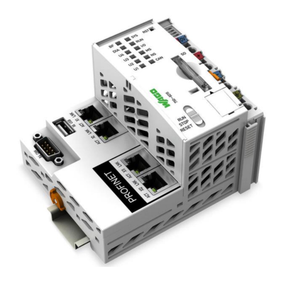
WAGO 750-8215 Manuals
Manuals and User Guides for WAGO 750-8215. We have
1
WAGO 750-8215 manual available for free PDF download: Manual
WAGO 750-8215 Manual (380 pages)
I/O-SYSTEM 750
Brand:
WAGO
| Category:
Controller
| Size: 3.8 MB
Table of Contents
Table of Contents
3
Table of Contents
7
Table of Contents
9
1 Notes about this Documentation
13
Validity of this Documentation
13
Copyright
13
Property Rights
14
Symbols
15
Number Notation
17
Font Conventions
17
Table 1: Number Notation
17
Table 2: Font Conventions
17
2 Important Notes
18
Legal Bases
18
Subject to Changes
18
Personnel Qualifications
18
Use of the 750 Series in Compliance with Underlying Provisions
18
Technical Condition of Specified Devices
19
Safety Advice (Precautions)
20
Licensing Terms of the Software Package Used
23
Special Use Conditions for ETHERNET Devices
23
3 Device Description
25
View
28
Figure 1: View
28
Table 3: Legend for Figure "View
28
Labeling
30
Manufacturing Number
30
Figure 2: Marking Area for Serial Numbers
30
Connectors
31
Data Contacts/Local Bus
31
Figure 3: Data Contacts
31
Power Jumper Contacts/Field Supply
32
Figure 4: Power Jumper Contacts
32
Table 4: Legend for Figure "Power Jumper Contacts
32
Cage Clamp
33
Connectors
33
Figure 5: CAGE CLAMP
33
Table 5: Legend for Figure "CAGE CLAMP
33
Service Interface
34
Figure 6: Service Interface (Closed and Open Flap)
34
Table 6: Service Interface
34
Network Connectors
35
Figure 7: Network Connections - X1, X2, X11, X12
35
Table 7: Legend for Figure "Network Connections - X1, X2, X11, X12
35
USB Service Interface
36
Figure 8: USB Service Interface - X6
36
Canopen
37
Figure 9: Canopen - X4 Fieldbus Connection
37
Table 8: Legend for Figure "Canopen - X4 Fieldbus Connection
37
Figure 10: Canopen Standard Bus Termination
38
Display Elements
39
Power Supply Indicating Elements
39
Figure 11: Power Supply Indicating Elements
39
Table 9: Legend for Figure "Power Supply Indicating Elements
39
Fieldbus/System Indicating Elements
40
Figure 12: Fieldbus/System Indicating Elements
40
Table 10: Legend for Figure "Fieldbus/System Indicating Elements
40
Memory Card Indicating Elements
41
Figure 13: Indicating Elements, Memory Card Slot
41
Table 11: Legend for Figure "Indicating Elements, Memory Card Slot
41
Network Indicating Elements
42
Figure 14: Indicating Elements, RJ-45 Jacks
42
Table 12: Legend for Figure "Indicating Elements, RJ-45 Jacks
42
Operating Elements
43
Operating Mode Switch
43
Figure 15: Mode Selector Switch
43
Table 13: Mode Selector Switch
43
Reset Button
44
Figure 16: Reset Button
44
Slot for Memory Card
45
Figure 17: Slot for SD Memory Card
45
Schematic Diagram
46
Figure 18: Schematic Diagram
46
Technical Data
47
Mechanical Data
47
System Data
47
Power Supply
47
Table 14: Technical Data - Mechanical Data
47
Table 15: Technical Data - System Data
47
Table 16: Technical Data - Power Supply
47
Clock
48
Programming
48
Local Bus
48
Ethernet
48
Table 17: Technical Data - Clock
48
Table 18: Technical Data - Programming
48
Table 19: Technical Data - Local Bus
48
Table 20: Technical Data - ETHERNET
48
Canopen
49
Profinet Io
49
USB Service Interface
49
Table 21: Technical Data - Canopen
49
Table 22: Technical Data - PROFINET
49
Table 23: Technical Data - USB-Service Interface
49
Connection Type
50
Climatic Environmental Conditions
50
Table 24: Technical Data - Field Wiring
50
Table 25: Technical Data - Power Jumper Contacts
50
Table 26: Technical Data - Data Contacts
50
Table 27: Technical Data - Climatic Environmental Conditions
50
Approvals
51
Standards and Guidelines
52
4 Function Description
53
Network
53
Figure 19: Network Structure
53
Interface Configuration
53
Table 28: Legend for Figure "Network Structure
53
Network Security
55
Users and Passwords
55
Services and Users
55
WBM User Group
56
Linux User Group
56
SNMP User Group
56
Table 29: WBM Users
56
Table 30: Linux
56
Web Protocols for WBM Access
57
TLS Encryption
57
Root Certificates
59
Host Name/Domain Name
60
Network Configuration
60
Routing
60
DHCP Client
63
DHCP Server
63
Network Services
63
Table 31: List of Parameters Transmitted Via DHCP
64
DNS Server
65
Cloud Connectivity Functionality
66
Figure 20: Connecting the Controller to a Cloud Service (Example)
66
Components of the Cloud Connectivity Software Package
67
Table 32: Components of the Cloud Connectivity Software Package
67
Memory Card Function
68
Formatting
68
Backup Function
70
Data Backup
70
Restore Function
71
Inserting a Memory Card During Operation
73
Removing the Memory Card During Operation
73
Load Boot Project
74
Setting the Home Directory for the Runtime System
74
Table 33: Loading a Boot Project
75
Licensed Software Components
76
5 Mounting
77
Installation Position
77
Overall Configuration
77
Mounting Onto Carrier Rail
79
Carrier Rail Properties
79
WAGO DIN Rails
80
Spacing
80
Figure 21: Spacing
80
Table 34: WAGO DIN Rails
80
Mounting Sequence
81
Inserting Devices
82
Figure 22: Release Tab of Controller
82
Inserting the Controller
82
6 Connect Devices
83
Connecting a Conductor to the CAGE CLAMP
83
Figure 23: Connecting a Conductor to a CAGE CLAMP
83
Power Supply Concept
84
Overcurrent Protection
84
7 Commissioning
85
Switching on the Controller
85
Determining the IP Address of the Host PC
86
Setting an IP Address
87
Table 35: Default IP Addresses for ETHERNET Interfaces
87
Table 36: Network Mask 255.255.255.0
87
Assigning an IP Address Using DHCP
88
Figure 24: "Open DHCP", Example Figure
88
Changing an IP Address Using the "CBM" Configuration Tool and a Terminal Program
89
Figure 25: CBM Main Menu (Example)
89
Figure 26: CBM - Selecting "Networking
90
Figure 27: CBM - Selecting "TCP/IP
90
Figure 28: CBM - Selecting "IP Address
90
Figure 29: CBM - Selecting the IP Address
91
Figure 30: CBM - Entering a New IP Address
91
Changing an IP Address Using "WAGO Ethernet Settings
92
Figure 31: "WAGO Ethernet Settings" - Starting Screen (Example)
92
Figure 32: "WAGO Ethernet Settings" - "Network" Tab
93
Temporarily Setting a Fixed IP Address
94
Testing the Network Connection
95
Figure 33: Example of a Function Test
95
Changing Passwords
96
Shutdown/Restart
97
Initiating Reset Functions
98
Cold Start Reset
98
Software Reset
98
Warm Start Reset
98
Configuration
99
Configuration Via Web-Based-Management (WBM)
100
Figure 34: Entering Authentication
101
WBM User Administration
101
Figure 35: Password Reminder
102
Table 37: User Settings in the Default State
102
Table 38: Access Rights for WBM Pages
102
Figure 36: WBM Browser Window (Example)
104
General Information about the Page
104
Figure 37: WBM Status Information (Example)
105
Status Information" Page
107
Controller Details" Group
107
Network Details Xn" Group(S)
107
Table 39: WBM "Status Information" Page - "Controller Details" Group
107
Table 40: WBM "Status Information Page - "Network Details Xn" Group(S)
107
PLC Runtime Information" Page
108
PLC Runtime" Group
108
Table 41: WBM "PLC Runtime Information" Page - "PLC Runtime" Group
108
General PLC Runtime Configuration" Page
109
General PLC Runtime Configuration" Group
109
Table 42: WBM "General PLC Runtime Configuration" Page - "General PLC
109
PLC Webvisu" Page
110
Webserver Configuration" Group
110
Table 43: WBM "PLC Webvisu" Page - "Webserver Configuration" Group
110
Configuration of Host and Domain Name" Page
111
Hostname" Group
111
Table 44: WBM "Configuration of Host and Domain Name" Page - "Hostname" Group
111
Domain Name" Group
112
Table 45: WBM "Configuration of Host and Domain Name" Page - "Domain
112
TCP/IP Configuration" Page
113
IP Configuration (Xn)" Group(S)
113
Table 46: WBM "TCP/IP Configuration" Page - "IP Configuration (Xn)" Group(S)
113
Default Gateway N" Groups
114
Table 47: WBM "TCP/IP Configuration" Page - "Default Gateway N" Group
114
DNS Server" Group
115
Table 48: WBM "TCP/IP Configuration" Page - "DNS Server" Group
115
Routing" Page
116
General Routing Configuration" Group
116
Table 49: WBM "Routing" Page - "General Routing Configuration" Group
116
Static Routes" Group
117
Table 50: WBM "Routing" Page - "Static Routes" Group
117
Dynamic Routes" Group
118
IP Masquerading" Group
118
Table 51: WBM "Routing" Page - "IP-Masquerading" Group
118
Port Forwarding" Group
119
Table 52: WBM "Routing" Page - "Port Forwarding" Group
119
General Firewall Configuration" Page
120
Global Firewall Parameters" Group
120
Table 53: WBM "General Firewall Configuration" Page - "Global Firewall
120
Firewall Parameters Interface XXX" Group
121
Table 54: WBM "General Firewall Configuration" Page - "Firewall Parameter
121
Configuration of MAC Address Filter" Page
122
Global MAC Address Filter State" Group
122
Table 55: WBM "Configuration of MAC Address Filter" Page - "Global MAC
122
MAC Address Filter State Xn" Group
123
MAC Address Filter Whitelist" Group
123
Table 56: WBM "Configuration of MAC Address Filter" Page - "MAC Address
123
Table 57: WBM "Configuration of MAC Address Filter" Page - "MAC Address
123
Configuration of User Filter" Page
124
User Filter" Group
124
User Filter N" Group
124
Table 58: WBM "Configuration of User Filter" Page - "User Filter" Group
124
Table 59: WBM "Configuration of User Filter" Page - "User Filter N" Group
124
Add New User Filter" Group
125
Table 60: WBM "Configuration of User Filter" Page - "Add New User Filter
125
Configuration of Time and Date" Page
126
Date on Device" Group
126
Time on Device" Group
126
Table 61: WBM "Configuration of Time and Date" Page - "Date on Device" Group
126
Table 62: WBM "Configuration of Time and Date" Page - "Time on Device
126
Time Zone" Group
127
Table 63: WBM "Configuration of Time and Date" Page - "Time Zone" Group
127
TZ String" Group
128
Table 64: WBM "Configuration of Time and Date" Page - "TZ String" Group
128
Change Password for Selected User" Group
129
Table 65: WBM "Configuration of the Users for the Web-Based Management" Page - "Change Password for Selected User" Group
129
Create Bootable Image" Page
130
Create Bootable Image from Active Partition
130
Table 66: WBM "Create Bootable Image" Page - "Create Bootable Image from Active Partition" Group
130
Configuration of Service Interface" Page
132
Service Interface Assigned To" Group
132
Assign Owner of Service Interface (Enabled after Next Controller Reboot)" Group
132
Table 67: WBM "Configuration of Serial Interface RS-232" Page - "Assign Owner
132
Reboot Controller" Page
133
Reboot Controller" Group
133
Firmware Backup" Page
134
Table 68: "Firmware-Backup" WBM Page
134
Firmware Restore" Page
136
Table 69: "Firmware Restore" WBM Page
136
System Partition" Page
138
Current Active Partition" Group
138
Set Inactive Partition Active" Group
138
Mass Storage" Page
139
Device Name>" Group(S)
139
Device Name> - Create New Filesystem" Group(S)
139
Table 70: WBM "Mass Storage" Page - "<Device Name>" Group
139
Table 71: WBM "Mass Storage" Page - "<Device Name> - Create New Filesystem" Group
139
Software Uploads" Page
140
Upload New Software" Group
140
Activate New Software" Group
140
Table 72: WBM "Software Uploads" Page - "Upload New Software" Group
140
Table 73: WBM "Software Uploads" Page - "Activate New Software" Group
140
Configuration of Network Services" Page
141
Telnet" Group
141
FTP" Group
141
FTPS" Group
141
Table 74: WBM "Configuration of Network Services" Page - "Telnet" Group
141
Table 75: WBM "Configuration of Network Services" Page - "FTP" Group
141
Table 76: WBM "Configuration of Network Services" Page - "FTPS" Group
141
HTTP" Group
142
HTTPS" Group
142
WAGO-I/O-CHECK" Group
142
Table 77: WBM "Configuration of Network Services" Page - "HTTP" Group
142
Table 78: WBM "Configuration of Network Services" Page - "HTTPS" Group
142
Table 79: WBM "Configuration of Network Services" Page - "I/O-CHECK" Group
142
OPC UA" Group
143
Table 80: WBM "Configuration of Network Services" Page - "OPC UA" Group
143
Configuration of NTP Client" Page
144
NTP Client Configuration" Group
144
NTP Single Request" Group
144
Table 81: WBM "Configuration of NTP Client" Page - "NTP Client Configuration" Group
144
Configuration of PLC Runtime Services" Page
145
General Configuration" Group
145
E!Runtime" Group
145
Table 82: WBM "Configuration of PLC Runtime Services" Page - "General
145
Table 83: WBM "Configuration of CODESYS Services" Page - "E!Runtime
145
SSH Server Settings" Page
146
SSH Server" Group
146
Table 84: WBM "SSH Server Settings" Page - "SSH Server" Group
146
TFTP Server" Page
147
TFTP Server" Group
147
Table 85: WBM "TFTP Server" Page - "TFTP Server" Group
147
DHCP Configuration" Page
148
DHCP Configuration Xn" Group
148
Table 86: WBM "DHCP Configuration" - "DHCP Configuration Xn" Group
148
Configuration of DNS Service" Page
149
DNS Service" Group
149
Table 87: WBM "Configuration of DNS Service" Page - "DNS Service" Group
149
Modbus Services Configuration" Page
150
Modbus TCP" Group
150
Modbus UDP" Group
150
Table 88: WBM "Modbus Services Configuration" Page - "Modbus TCP" Group
150
Table 89: WBM "Modbus Configuration Services" Page - "Modbus UDP" Group
150
Configuration of Cloud Connectivity" Page
151
Software Version" Group
151
Status" Group
151
Table 90: WBM "Configuration of Cloud Connectivity" Page - "Software Version" Group
151
Table 91: WBM "Configuration of Cloud Connectivity" Page - "Status" Group
151
Settings" Group
152
Table 92: WBM "Configuration of Cloud Connectivity" Page - "Settings" Group
152
Table 93: Dependencies of the Selection and Input Fields for the Selected Cloud Platform
155
Configuration of General SNMP Parameters" Page
157
General SNMP Configuration" Group
157
Table 94: WBM "Configuration of General SNMP Parameters" Page - "General
157
Configuration of SNMP V1/V2C Parameters" Page
158
SNMP V1/V2C Manager Configuration" Group
158
Actually Configured Trap Receivers" Group(S)
158
Table 95: WBM "Configuration of SNMP V1/V2C Parameters" Page - "SNMP
158
Table 96: WBM "Configuration of SNMP V1/V2C Parameters" Page - "Actually
158
Trap Receiver N" Group(S)
159
Add New Trap Receiver" Group
159
Table 97: WBM "Configuration of SNMP V1/V2C Parameters" Page - "Trap
159
Table 98: WBM "Configuration of SNMP V1/V2C Parameters" Page - "Add New
159
Configuration of SNMP V3 Users" Page
160
Actually Configured V3 Users" Group(S)
160
V3 User N" Group(S)
160
Table 99: WBM "Configuration of SNMP V3" Page - "Actually Configured V3
160
Table 100: WBM "Configuration of SNMP V3 Users" Page - "V3 User N" Group(S)
160
Add New V3 User" Group
161
Table 101: WBM "Configuration of SNMP V3 Users" Page - "Add New V3 User
161
Diagnostic Information" Page
162
Table 102: WBM "Diagnostic Information" Page
162
Configuration of Openvpn and Ipsec" Page
163
Openvpn" Group
163
Ipsec" Group
163
Table 103: WBM "Configuration of Openvpn and Ipsec" Page - "Openvpn" Group
163
Table 104: WBM "Configuration of Openvpn and Ipsec" Page - "Ipsec" Group
163
Certificate Upload" Group
164
Certificate List" Group
164
Private Key List" Group
164
Table 105: WBM "Configuration of Openvpn and Ipsec" Page - "Certificate
164
Table 106: WBM "Configuration of Openvpn and Ipsec" Page - "Certificate List" Group
164
Table 107: WBM "Configuration of Openvpn and Ipsec" Page - "Private Key
164
Security Settings" Page
165
Transport Layer Security Settings" Group
165
Table 108: "Security Settings" WBM Page - "Transport Layer Security Settings" Group
165
Advanced Intrusion Detection Environment (AIDE) Page
166
Run AIDE Check at Startup" Group
166
Control AIDE and Show Log" Group
166
Table 109: "Advanced Intrusion Detection Environment (AIDE) WBM Page" - "Run AIDE Check at Startup" Group
166
Table 110: "Advanced Intrusion Detection Environment (AIDE)" WBM Page - "Control AIDE and Show Log" Group
166
Open Source Licenses" Page
167
WAGO Licenses" Page
168
Configuration Via Console-Based-Management-Tool (CBM) Using a Terminal Program
169
Figure 38: CBM Main Menu (Example)
169
CBM Menu Structure Overview
170
Table 111: CBM Menu Structure
170
Information" > "Controller Details" Submenu
173
Information" Menu
173
Table 112: "Information" Menu
173
Table 113: "Information" > "Controller Details" Submenu
173
Information" > "Network Details" Submenu
174
Table 114: "Information" > "Network Details" Submenu
174
Information" > "Runtime Version" Submenu
175
PLC Runtime" > "Information" Submenu
175
PLC Runtime" Menu
175
Table 115: "PLC Runtime" Menu
175
Table 116: "PLC Runtime" > "Information" Submenu
175
Table 117: "PLC Runtime" > "Information" > "Runtime Version" Submenu
175
General Configuration" > "PLC Runtime Version" Submenu
176
PLC Runtime" > "General Configuration" Submenu
176
Table 118: "PLC Runtime" > "General Configuration" Submenu
176
Table 119: "PLC Runtime" > "General Configuration" > "PLC Runtime Version
176
Table 120: "PLC Runtime" > "General Configuration" > "Home dir on SD Card
177
PLC Runtime" > "Webvisu" Submenu
178
Table 121: "PLC Runtime" > "Webvisu" Submenu
178
Networking" > "Host/Domain Name" Submenu
179
Networking" Menu
179
Table 122: "Networking" Menu
179
Table 123: "Networking" > "Host/Domain Name" Submenu
179
Host/Domain Name" > "Domain Name" Submenu
180
Host/Domain Name" > "Hostname" Submenu
180
Networking" > "TCP/IP" Submenu
180
Table 124: "Networking" > "Hostname" Submenu
180
Table 125: "Networking" > "Host/Domain Name" > "Domain Name" Submenu
180
Table 126: "Networking" > "TCP/IP" Submenu
180
IP Address" > "Xn" Submenu
181
Table 127: "Networking" > "IP Address" Submenu
181
Table 128: "Networking" > "TCP/IP" > "IP Address" Submenu > "Xn
181
TCP/IP" > "IP Address" Submenu
181
Default Gateway" > "Default Gateway N" Submenu
182
Table 129: "Networking" > "TCP/IP" > "Default Gateway" Submenu
182
Table 130: "Networking" > "TCP/IP" > "Default Gateway" > "Default Gateway N
182
TCP/IP" > "Default Gateway" Submenu
182
Table 131: "Networking" > "TCP/IP" > "DNS Server" Submenu
183
TCP/IP" > "DNS Server" Submenu
183
Firewall" Menu
184
Table 132: "Firewall" Menu
184
Firewall" > "General Configuration" Submenu
185
Table 133: "Firewall" > "General Configuration" Submenu
185
General Configuration" > "Interface XXX" Submenu
186
Table 134: "Firewall" > "General Configuration" > "Interface XXX" Submenu
186
Firewall" > "MAC Address Filter" Submenu
188
Table 135: "Firewall" > "MAC Address Filter" Submenu
188
MAC Address Filter Whitelist" > "Add New / no (N)" Submenu
189
MAC Address Filter" > "MAC Address Filter Whitelist" Submenu189
189
Table 136: "Firewall" > "MAC Address Filter" > "MAC Address Filter Whitelist
189
Table 137: "Firewall" > "MAC Address Filter" > "MAC Address Filter Whitelist
189
Firewall" > "User Filter" Submenu
190
Table 138: "Firewall" > "User Filter" Submenu
190
Table 139: "Firewall" > "User Filter" > "Add New / no (N)" Submenu
191
User Filter" > "Add New / no (N)" Submenu
191
Clock" Menu
192
Table 140: "Clock" Menu
192
Administration" Menu
193
Table 141: "Administration" Menu
193
Administration" > "Create Image" Submenu
194
Administration" > "Users" Submenu
194
Table 142: "Administration" > "Users" Submenu
194
Table 143: "Administration" > "Create Image" Submenu
194
Package Server" > "Firmware Backup" Submenu
195
Package Server" Menu
195
Table 144: "Package Server" Menu
195
Table 145: "Package Server" > "Firmware Backup" Menu
195
Firmware Backup" > "Auto Update Feature" Submenu
196
Firmware Backup" > "Destination" Submenu
196
Table 146: "Package Server" > "Firmware Backup" > "Auto Update Feature
196
Table 147: "Package Server" > "Firmware Backup" > "Auto Update Feature
196
Firmware Restore" > "Select Package" Submenu
197
Package Server" > "Firmware Restore" Submenu
197
Table 148: "Package Server" > "Firmware Restore" Menu
197
Table 149: "Package Server" > "Firmware Restore" > "Select Package" Menu
197
Package Server" > "System Partition" Submenu
198
Table 150: "Package Server" > "System Partition" Submenu
198
Mass Storage" > "SD Card" Submenu
199
Mass Storage" Menu
199
Table 151: "Mass Storage" Menu
199
Table 152: "Mass Storage" > "SD Card" Menu
199
Software Uploads" Menu
200
Ports and Services" Menu
201
Table 153: "Ports and Services" Menu
201
Ports and Services" > "FTP" Submenu
202
Ports and Services" > "Telnet" Submenu
202
Table 154: "Ports and Services" > "Telnet" Submenu
202
Table 155: "Ports and Services" > "FTP" Submenu
202
Ports and Services" > "FTPS" Submenu
203
Ports and Services" > "HTTP" Submenu
203
Table 156: "Ports and Services" > "FTPS" Submenu
203
Table 157: "Ports and Services" > "HTTP" Submenu
203
Ports and Services" > "HTTPS" Submenu
204
Ports and Services" > "NTP" Submenu
204
Table 158: "Ports and Services" > "HTTPS" Submenu
204
Table 159: "Ports and Services" > "NTP" Submenu
204
Ports and Services" > "SSH" Submenu
205
Ports and Services" > "TFTP" Submenu
205
Table 160: "Ports and Services" > "SSH" Submenu
205
Table 161: "Ports and Services" > "TFTP" Submenu
205
DHCPD" > "Xn" Submenu
206
Ports and Services" > "DHCPD" Submenu
206
Table 162: "Ports and Services" > "DHCPD" Submenu
206
Table 163: "Ports and Services" > "DHCPD" > "Xn" Submenu
206
Ports and Services" > "DNS" Submenu
207
Table 164: "Ports and Services" > "DNS" Submenu
207
Ports and Services" > "IOCHECK PORT" Submenu
208
Ports and Services" > "Modbus TCP" Submenu
208
Table 165: "Ports and Services" > "IOCHECK PORT" Submenu
208
Table 166: "Ports and Services" > "Modbus TCP" Submenu
208
Ports and Services" > "Modbus UDP" Submenu
209
Ports and Services" > "OPC UA" Submenu
209
Table 167: "Ports and Services" > "Modbus UDP" Submenu
209
Table 168: "Ports and Services" > "OPC UA" Submenu
209
Firewall Status" Submenu
210
Table 169: "Ports and Services" > "Firewall Status" Submenu
210
PLC Runtime Services" > "E!Runtime" Submenu
211
Ports and Services" > "PLC Runtime Services" Submenu
211
Table 170: "Ports and Services" > "PLC Runtime Services" Submenu
211
Table 171: "Ports and Services" > "PLC Runtime Services" > "E!Runtime
211
SNMP" > "General SNMP Configuration" Submenu
212
SNMP" Menu
212
Table 172: "SNMP" Menu
212
Table 173: "SNMP" > "General SNMP Configuration" Submenu
212
SNMP" > "SNMP V1/V2C Manager Configuration" Submenu
213
SNMP" > "SNMP V1/V2C Trap Receiver Configuration" Submenu
213
Table 174: "SNMP" > "SNMP V1/V2C Manager Configuration" Submenu
213
Table 175: "SNMP" > "SNMP V1/V2C Trap Receiver Configuration" Submenu
213
SNMP" > "SNMP V3 Configuration" Submenu
214
Table 176: "SNMP" > "SNMP V3 Configuration" Submenu
214
SNMP" > "(Secure)Snmp Firewalling" Submenu
215
Table 177: "SNMP" > "(Secure )SNMP Firewalling" Submenu
215
Configuration Using "WAGO Ethernet Settings
216
Figure 39: "WAGO Ethernet Settings" - Start Screen
216
Figure 40: "WAGO Ethernet Settings" - Communication Link
217
Figure 41: "WAGO Ethernet Settings" - Identification Tab (Example)
218
Identification Tab
218
Figure 42: "WAGO Ethernet Settings" - Network Tab
219
Network Tab
219
Figure 43: "WAGO Ethernet Settings" - Protocol Tab
221
PLC Tab
221
Figure 44: "WAGO Ethernet Settings" - Status Tab
222
Status Tab
222
E!Runtime Runtime Environment
223
General Notes
223
CODESYS V3 Priorities
224
Table 178: CODESYS V3 Priorities
224
Memory Spaces under E!Runtime
225
Figure 45: Remanent Main Memory
225
Function Block Limitation
225
Program and Data Memory
225
Remanent Memory
225
Modbus - E!Runtime
226
Modbus Address Overview
226
Figure 46: Modbus Address Overview
226
Modbus Registers
227
Table 179: WAGO Modbus Registers
227
Figure 47: State Diagram, ADVANCED_WATCHDOG Operation Mode
229
Modbus Watchdog
229
Figure 48: State Diagram, SIMPLE_WATCHDOG Operation Mode
230
Figure 49: State Diagram, Switching Operation Modes
230
Register 0Xfa00 - Watchdog Command
231
Table 180: Watchdog Commands
231
Register 0Xfa01 - Watchdog Timeout
232
Register 0Xfa02 - Watchdog Status
232
Table 181: Watchdog Status
232
Register 0Xfa03 - Watchdog Config
233
Table 182: Watchdog Configuration
233
Modbus TCP Connection Watchdog Register
234
Electronic Nameplate
235
Firmware Loader/Boot Loader
235
Firmware Version
235
Hardware Version
235
Modbus Process Image Registers
235
Modbus Process Image Version
235
Order Number
235
PLC Status Register
235
Status Registers
235
Constant Registers
236
Live Register
236
Estimating the Modbus Master CPU Load
237
Canopen Master and Slave
238
Object Directory
238
Table 183: Overview of Addresses in the Object Directory
238
Communications Profile
239
Master Configuration
243
Data Exchange
245
Controller Communication Objects
245
Fieldbus-Specific Addressing
245
Table 184: Indexing of "IEC 61131-3" Variable Data in the Object Directory
246
Table 185: Fieldbus Access to PFC Output Data
247
Figure 50: Correlation between "IEC 61131-3" Variables and PFC Variables
248
Examples for the Definition of PFC Fieldbus Variables
249
CODESYS Access to PFC Variables
249
Table 186: Examples for CODESYS Access to PFC Variables
249
Maximum Indices
250
Table 187: Maximum Indices and Sub-Indices for "IEC 61131-3" Variables
250
Table 188: Example of "IEC 61131-3" Output Variables
251
Canopen Master Control Configuration
252
Selecting the Master
252
Figure 51: Adding the Canopen Master
252
Setting the Master Parameters
253
Figure 52: Basic Parameters Tab (Master)
253
Table 189: Description of Basic Parameters (Master)
253
Figure 53: CAN Parameters Tab (Master)
254
Table 190: Description of the CAN Parameters (Master)
254
Adding Slaves
255
Figure 54: Module Parameters Tab (Master)
255
Table 191: Description of the Module Parameters (Master)
255
Figure 55: Adding a Canopen Slave
256
Figure 56: Basic Parameters Tab (Slave)
257
Table 192: Description of Basic Parameters (Slave)
257
Figure 57: CAN Parameters Tab (Slave)
258
Table 193: Description of the CAN Parameters (Slave)
259
Figure 58: CAN Module Selection Tab
261
Configuring the Slave Pdos
262
Figure 59: PDO Mapping Tab
262
Figure 60: PDO Properties Window
263
Table 194: Receiving and Sending Description for PDO Mapping
263
Table 195: Description of the PDO Properties Window
264
Configuring the Service Data Objects
265
Figure 61: Service Data Objects Tab
265
Figure 62: Adapting Sdos
266
Figure 63: "Module Parameters" Tab (Slave)
267
Table 196: Description of the Module Parameters (Slave)
267
Canopen Slave Control Configuration
268
Figure 64: Attaching a Canopen Slave
268
Figure 65: Configuring a Canopen Slave
268
Canopen Variables Configuration
269
Figure 66: Configuration of the Canopen Slave Variables
269
Table 197: Description of the Canopen Slave Variables Window
269
Configuring of Canopen Parameters
270
Figure 67: Configuration of Canopen Slave Parameters
270
Table 198: Description of Canopen Slave Settings
270
Fieldbus Coupler Diagnostics
271
Busdiag.lib
271
Creating Diagnostics in CODESYS 2.3
272
Figure 68: "Resources" Tab
272
Figure 69: "Open" Dialog Window
273
Figure 70: Module Icon in the Menu Bar; FUP Programming Language
273
Figure 71: Instance of the Function Block Diaggetbusstate() in FUP
273
Calling the Diagnostics Function Block
274
Figure 72: Function Block Diaggetstate() in FUP
274
Figure 73: Off-Line View of Variable Window in CODESYS
274
Performing Bus Diagnostics Using Diaggetbusstate()
275
Figure 74: Online View of Variable Window (Top Window) in FUP
276
Figure 75: Example of Diagnostics
276
Performing Subscriber Diagnostics Using Diaggetstate()
277
Figure 76: Diaggetstate() Diagnostic Call
277
Table 199: Diagnostic Information Bits
277
Evaluating the Canopen Diagnostics (Emergency Messages)
279
Figure 77: Online View of the EXTENDEDINFO Array in Binary Representation
279
Wagocanopendiag.lib
281
Data Exchange between Simple CAN Subscribers and PFC200 in the Canopen Network
282
Figure 78: Attaching the Canopen Master
282
Figure 79: Setting the Baud Rate
283
Figure 80: EDS File "Generic CAN Device
283
Figure 81: "Module Parameters" Tab
284
Figure 82: "CAN Parameters" Tab
284
Data Exchange between CAN Subscribers and the PFC200 in a CAN Layer2 Network
285
Figure 83: Attaching the CAN Layer2 Device
285
Profinet
286
General Description
286
Configuration and Parameterization with E!Cockpit
287
PROFINET Data Point Configurator
287
Figure 84: "PROFINET I-Device" Tab
288
Figure 85: Module Context Menu
290
Diagnostics
291
Operating and Status Messages
291
Power Supply Indicating Elements
291
Figure 86: Power Supply Indicating Elements
291
Table 201: System Power Supply Diagnistics
291
Table 202: Field-Side Supply Diagnostics
291
Fieldbus/System Indicating Elements
292
Figure 87: Fieldbus/System Indicating Elements
292
Table 203: Diagnostics Via SYS LED
292
Table 204: RUN LED Diagnostics
293
Table 205: Diagnostics I/O LED
294
Table 206: MS-LED Diagnostics
295
Table 207: Diagnostics CAN LED
296
Table 208: "BF" Diagnostics LED
297
Table 209: "DIA" Diagnostics LED
298
Network Indicating Elements
299
Figure 88: Indicating Elements, RJ-45 Jacks
299
Table 210: LNK-LED Diagnostics
299
Table 211: ACT-LED Diagnostics
299
Diagnostics Messages Via Flashing Sequences
300
Flashing Sequences
300
Figure 89: Flashing Sequence Process Diagram
301
Example of a Diagnostics Message Indicated by a Flashing Sequence
302
Meaning of Blink Codes and Procedures for Troubleshooting
303
Table 212: Overview of Error Codes, I/O LED
303
Table 213: Error Code 1, Explanation of Blink Codes and Procedures for Troubleshooting
304
Table 214: Error Code 2, Explanation of Blink Codes and Procedures for Troubleshooting
305
Table 215: Error Code 3, Explanation of Blink Codes and Procedures for Troubleshooting
306
Table 216: Error Code 4, Explanation of Blink Codes and Procedures for Troubleshooting
307
Table 217: Error Code 5, Explanation of Blink Codes and Procedures for Troubleshooting
307
Table 218: Error Code 7, Explanation of Blink Codes and Procedures for Troubleshooting
307
Table 219: Error Code 9, Explanation of Blink Codes and Procedures for Troubleshooting
308
Meaning of Blink Codes and Procedures for Troubleshooting
309
Table 220: Overview of MS-LED Error Codes
309
Table 221: Error Code 1, Explanation of Blink Codes and Procedures for Troubleshooting
309
Service
310
Inserting and Removing the Memory Card
310
Inserting the Memory Card
310
Removing the Memory Card
310
Figure 90: Inserting the Memory Card
310
Firmware Changes
312
Perform Firmware Upgrade
312
Perform Firmware Downgrade
313
Factory Reset
314
Updating Root Certificates
315
Removal
316
Removing Devices
316
Removing the Controller
316
Figure 91: Release Tab of Controller
316
Disposal
317
Electrical and Electronic Equipment
317
Packaging
317
Use in Hazardous Environments
319
Marking Configuration Examples
320
Marking for Europe According to ATEX and Iecex
320
Figure 92: Marking Example According to ATEX and Iecex
320
Figure 93: Text Detail - Marking Example According to ATEX and Iecex
320
Table 222: Description of Marking Example According to ATEX and Iecex
321
Figure 94: Marking Example for Approved Ex I I/O Module According to ATEX and Iecex
322
Figure 95: Text Detail - Marking Example for Approved Ex I I/O Module According to ATEX and Iecex
322
Table 223: Description of Marking Example for Approved Ex I I/O Module According to ATEX and Iecex
323
Marking for the United States of America (NEC) and Canada (CEC)324
324
Figure 96: Marking Example According to NEC
324
Figure 97: Text Detail - Marking Example According to NEC 500
324
Table 224: Description of Marking Example According to NEC 500
324
Figure 98: Text Detail - Marking Example for Approved Ex I I/O Module
325
Figure 99: Text Detail - Marking Example for Approved Ex I I/O Module
325
Table 225: Description of Marking Example for Approved Ex I I/O Module
325
Table 226: Description of Marking Example for Approved Ex I I/O Modules
325
Figure 100: Text Detail - Marking Example for Approved Ex I I/O Modules
326
Table 227: Description of Marking Example for Approved Ex I I/O Modules
326
Installation Regulations
327
Special Notes Including Explosion Protection
327
Special Notes Regarding ANSI/ISA Ex
329
Appendix
330
Process Data Architecture
330
Digital Input Modules
331
Channel Digital Input Module with Diagnostics
331
Channel Digital Input Modules
331
Table 228: 1 Channel Digital Input Module with Diagnostics
331
Table 229: 2 Channel Digital Input Modules
331
Table 230: 2 Channel Digital Input Module with Diagnostics
331
Channel Digital Input Module with Diagnostics and Output Process Data
332
Channel Digital Input Modules
332
Table 231: 2 Channel Digital Input Module with Diagnostics and Output Process Data
332
Table 232: 4 Channel Digital Input Modules
332
Table 233: 8 Channel Digital Input Modules
332
Channel Digital Input Module NAMUR with Diagnostics and Output Process Data
333
Table 234: 8 Channel Digital Input Module NAMUR with Diagnostics and Output Process Data
333
Channel Digital Input Module PTC with Diagnostics and Output Process Data
334
Table 235: 8 Channel Digital Input Module PTC with Diagnostics and Output Process Data
334
Channel Digital Input Modules
335
Table 236: 16 Channel Digital Input Modules
335
Digital Output Modules
336
Channel Digital Output Module with Input Process Data
336
Channel Digital Output Modules
336
Table 237: 1 Channel Digital Output Module with Input Process Data
336
Table 238: 2 Channel Digital Output Modules
336
Channel Digital Input Modules with Diagnostics and Input Process Data
337
Table 239: 2 Channel Digital Input Modules with Diagnostics and Input Process Data
337
Table 240: 2 Channel Digital Input Modules with Diagnostics and Input Process Data 75X-506
337
Channel Digital Output Modules
338
Channel Digital Output Modules with Diagnostics and Input Process Data
338
Channel Digital Output Module
338
Table 241: 4 Channel Digital Output Modules
338
Table 242: 4 Channel Digital Output Modules with Diagnostics and Input Process Data
338
Table 243: 8 Channel Digital Output Module
338
Channel Digital Output Modules with Diagnostics and Input Process Data
339
Channel Digital Output Modules
339
Table 244: 8 Channel Digital Output Modules with Diagnostics and Input Process Data
339
Table 245: 16 Channel Digital Output Modules
339
Channel Digital Input/Output Modules
340
Table 246: 8 Channel Digital Input/Output Modules
340
Analog Input Modules
341
Channel Analog Input Modules
341
Table 247: 1 Channel Analog Input Modules
341
Table 248: 2 Channel Analog Input Modules
341
Channel Analog Input Modules HART
342
Channel Analog Input Modules
343
Table 249: 2-Channel Analog Input Modules HART
343
Table 250:: 2 Channel Analog Input Modules HART + 6 Bytes Mailbox
343
Table 251: 4 Channel Analog Input Modules
343
Channel Analog Input Modules
344
Table 252: 8 Channel Analog Input Modules
344
3-Phase Power Measurement Module
345
Table 253: 3-Phase Power Measurement Module
345
Table 254: 3-Phase Power Measurement Modules 750-494, -495, (and All Variations)
346
Analog Output Modules
347
Channel Analog Output Modules
347
Table 255: 2 Channel Analog Output Modules
347
Table 256: 4 Channel Analog Output Modules
347
Specialty Modules
348
Counter Modules
348
Table 257: Counter Modules 750-404, (and All Variations Except of /000-005)
348
Table 258: Counter Modules 750-404/000-005, 753-404/000-005
349
Table 259: Counter Modules 750-633
350
Table 260: Counter Modules 750-638, 753-638
350
Pulse Width Modules
351
Serial Interface Modules with Alternative Data Format
351
Table 261: Pulse Width Modules 750-511, /XXX-XXX, 753-511
351
Serial Interface Modules with Standard Data Format
352
Serial Interface Modules
352
Table 262: Serial Interface Modules with Alternative Data Format
352
Table 263: Serial Interface Modules with Standard Data Format
352
Data Exchange Module
353
SSI Transmitter Interface Modules
353
Table 264: Serial Interface Modules 750-652, 753-652
353
Table 265: Data Exchange Module 750-654, -654/000-001
353
Incremental Encoder Interface Modules
354
Table 266: SSI Transmitter Interface Modules
354
Table 267: SSI Transmitter Interface I/O Modules with an Alternative Data Format (/000-004, -005, -007)
354
Table 269: Incremental Encoder Interface Modules 750-634
355
Table 270: Incremental Encoder Interface Modules 750-637, (and All Variations)
355
DC-Drive Controller
356
Table 271: Digital Pulse Interface Modules 750-635, 753-635
356
Table 272: DC-Drive Controller 750-636, -636/000-700, -636/000-800
356
Stepper Controller
357
Table 273: Stepper Controller 750-670, -671, -672
357
RTC Module
358
DALI Multi-Master Module
358
Table 274: RTC Module 750-640
358
Table 275: DALI Multi-Master Module 753-647 in the "Easy" Mode
359
Table 276: DALI Multi-Master Module 753-647 in the "Full" Mode
361
LON FTT Module
362
Enocean Radio Receiver
362
Table 277: LON ® FTT Module 753-648
362
Table 278: Enocean Radio Receiver 750-642
362
MP Bus Master Module
363
Bluetooth ® RF-Transceiver
363
Table 279: MP Bus Master Module 750-643
363
Vibration Velocity/Bearing Condition Monitoring VIB I/O
364
Table 280: Bluetooth
364
Table 281: Vibration Velocity/Bearing Condition Monitoring VIB I/O 750-645
364
KNX/EIB/TP1 Module
365
AS-Interface Master Module
365
Table 282: KNX/EIB/TP1 Module 753-646
365
Table 283: AS-Interface Master Module 750-655, 753-655
366
System Modules
367
System Modules with Diagnostics
367
Filter Module
367
Binary Space Module
367
Table 284: System Modules with Diagnostics 750-606, -611
367
Table 285: System Modules with Diagnostics 750-610, -611
367
Table 286: Filter Modules 750-624/020-002, 750-626/020-002
367
Table 287: Binary Space Module 750-622 (with Behavior Like 2 Channel Digital Input)
368
List of Figures
369
List of Tables
372
Advertisement
Advertisement
Related Products
WAGO 750-880
WAGO 750-880/025-000
WAGO 750-806
WAGO 750-881
WAGO 750-843
WAGO 750-872
WAGO 750-8202/040-000
WAGO 750-8202/040-001
WAGO 750-636/000-800
WAGO 750-636-025-000
WAGO Categories
I/O Systems
Control Unit
Power Supply
Switch
Controller
More WAGO Manuals
Login
Sign In
OR
Sign in with Facebook
Sign in with Google
Upload manual
Upload from disk
Upload from URL