WAGO 750-881 Manuals
Manuals and User Guides for WAGO 750-881. We have 3 WAGO 750-881 manuals available for free PDF download: Quickstart Reference

WAGO 750-881 Quickstart Reference (74 pages)
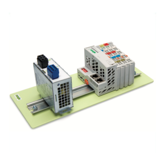
ETHERNET Programmable Fieldbus
Brand: WAGO
|
Category: I/O Systems
|
Size: 4 MB
Table of Contents
Advertisement
WAGO 750-881 Quickstart Reference (54 pages)
ETHERNET Programmable Fieldbus, 10/100 Mbit/s; digital and analog signals
Brand: WAGO
|
Category: I/O Systems
|
Size: 4 MB
Table of Contents

WAGO 750-881 Quickstart Reference (20 pages)
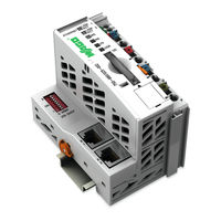
-I/O-SYSTEM 750 Programmable Fieldbus Controller ETHERNET
Brand: WAGO
|
Category: Controller
|
Size: 1 MB
Table of Contents
Advertisement
Advertisement