Sign In
Upload
Manuals
Brands
WAGO Manuals
Controller
750-806
WAGO 750-806 Manuals
Manuals and User Guides for WAGO 750-806. We have
2
WAGO 750-806 manuals available for free PDF download: Manual, Technical Description
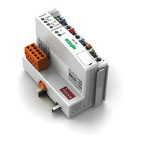
WAGO 750-806 Manual (214 pages)
Fieldbus Controller DeviceNetTM 16-bit CPU
Brand:
WAGO
| Category:
Controller
| Size: 5 MB
Table of Contents
Table of Contents
3
List of Figures/List of Tables
7
Table of Contents
7
Notes about this Documentation
8
Validity of this Documentation
8
Copyright
8
Symbols
9
Number Notation
11
Font Conventions
11
Table 1: Number Notation
11
Table 2: Font Conventions
11
Important Notes
12
Legal Bases
12
Subject to Changes
12
Personnel Qualifications
12
Use of the WAGO-I/O-SYSTEM 750 in Compliance with Underlying Provisions
12
Technical Condition of Specified Devices
13
Safety Advice (Precautions)
14
System Description
16
Figure 1: Fieldbus Node (Example)
16
Manufacturing Number
17
Figure 2: Marking Area for Serial Numbers
17
Component Update
18
Storage, Assembly and Transport
18
Assembly Guidelines/Standards
19
Power Supply
20
Isolation
20
Figure 3: Isolation for Fieldbus Couplers/Controllers (Example)
20
System Supply
21
Connection
21
Figure 4: System Supply Via Fieldbus Coupler/Controller (Left) and Via Internal System Supply Module (Right)
21
Table 3: Legend for Figure "System Supply Via Fieldbus Coupler/Controller (Left) and Via Internal System Supply Module (Right)
21
Dimensioning
22
Figure 5: System Voltage for Standard Couplers/Controllers and Extended ECO
22
Table 4: Alignment
22
Field Supply
25
Connection
25
Figure 6: Field Supply for Standard Couplers/Controllers and Extended ECO
25
Table 5: Legend for Figure "Field Supply for Standard Couplers/Controllers and Extended ECO Couplers
26
750-806 Fieldbus Controller Devicenet TM
26
Fusing
27
Figure 7: Supply Module with Fuse Carrier (Example 750-610)
27
Table 6: Power Supply Modules
27
Figure 8: Removing the Fuse Carrier
28
Figure 9: Opening the Fuse Carrier
28
Figure 10: Changing the Fuse
28
Figure 11: Fuse Modules for Automotive Fuses, Series 282
29
Figure 12: Fuse Modules for Automotive Fuses, Series 2006
29
Figure 13: Fuse Modules with Pivotable Fuse Carrier, Series 281
29
Figure 14: Fuse Modules with Pivotable Fuse Carrier, Series 2002
29
Supplementary Power Supply Regulations
30
Figure 15: Power Supply Concept
30
Table 7: Filter Modules for 24 V Supply
30
Supply Example
31
Figure 16: Supply Example for Standard Couplers/Controllers
31
Table 8: Legend for Figure "Supply Example for Fieldbus Coupler/Controller
32
750-806 Fieldbus Controller Devicenet TM
32
Power Supply Unit
33
Table 9: WAGO Power Supply Units (Selection)
33
Grounding
34
Grounding the DIN Rail
34
Framework Assembly
34
Insulated Assembly
34
Table 10: WAGO Ground Wire Terminals
34
Grounding Function
35
Figure 17: Carrier Rail Contact (Example)
35
Shielding
36
General
36
Bus Cables
36
Figure 18: Cable Shield at Ground Potential
36
Signal Lines
37
WAGO Shield Connecting System
37
Figure 19: Examples of the WAGO Shield Connecting System
37
Figure 20: Application of the WAGO Shield Connecting System
37
Device Description
38
View
40
Figure 21: View Devicenet
40
Table 11: Legend for Figure "View Devicenet TM Fieldbus Controller
41
Connectors
42
Device Supply
42
Figure 22: Device Supply
42
Fieldbus Connection
43
Figure 23: Fieldbus Connections, Series 231 (MCS)
43
Table 12: Pin Assignment for the Fieldbus Connection, Series 231 (MCS)
43
Display Elements
44
Figure 24: Display Elements
44
Table 13: Display Elements Fieldbus Status
44
Table 14: Display Elements Node Status
44
Table 15: Display Elements Supply Voltage
44
Operating Elements
45
Service Interface
45
Figure 25: Service Interface (Closed and Opened Flap)
45
Table 16: Legend for Figure "Service Interface (Closed and Opened Flap)
45
Mode Selector Switch
46
Figure 26: Mode Selector Switch (Closed and Open Damper of the Service Port)
46
Table 17: Legend for Figure „Mode Selector Switch
46
Table 18: Mode Selector Switch Positions, Static Positions on Poweron/Reset
47
Table 19: Mode Selector Switch Positions, Dynamic Positions During Ongoing
47
DIP Switch
48
Baud Rate Setting
48
Figure 27: DIP Switch
48
Figure 28: Example with Baud Rate Sent to 250 Kbaud
48
Table 20: Setting the Baud Rate Via DIP Switch
48
Station Address
49
Figure 29: Example with Station Address Set to 25
49
Technical Data
50
Device Data
50
System Data
50
Table 21: Technical Data, Device Data
50
Table 22: Technical Data, System Data
50
Devicenet TM Fieldbus
51
Power Supply
51
Accessories
51
Connection Type
51
Table 23: Technical Data, Devicenet TM Fieldbus
51
Table 24: Technical Data, Power Supply
51
Table 25: Technical Data, Accessories
51
Table 26: Technical Data - Field Wiring
51
Table 27: Technical Data - Power Jumper Contacts
51
Climatic Environmental Conditions
52
Mechanical Strength Acc. to IEC 61131-2
52
Table 28: Technical Data - Data Contacts
52
Table 29: Technical Data - Climatic Environmental Conditions
52
Table 30: Technical Data - Mechanical Strength Acc. to IEC 61131-2
52
Approvals
53
Standards and Guidelines
55
Mounting
56
Installation Position
56
Overall Configuration
56
Mounting Onto Carrier Rail
58
Carrier Rail Properties
58
WAGO DIN Rail
59
Spacing
59
Figure 30: Spacing
59
Table 31: WAGO DIN Rail
59
Mounting Sequence
60
Inserting and Removing Devices
61
Inserting the Fieldbus Coupler/Controller
62
Removing the Fieldbus Coupler/Controller
62
Figure 31: Release Tab Standard Fieldbus Coupler/Controller (Example)
62
Inserting the I/O Module
63
Figure 32: Insert I/O Module (Example)
63
Figure 33: Snap the I/O Module into Place (Example)
63
Removing the I/O Module
64
Figure 34: Removing the I/O Module (Example)
64
Connect Devices
65
Data Contacts/Internal Bus
65
Figure 35: Data Contacts
65
Power Contacts/Field Supply
66
Figure 36: Example for the Arrangement of Power Contacts
66
Connecting a Conductor to the CAGE CLAMP
67
Figure 37: Connecting a Conductor to a CAGE CLAMP
67
Function Description
68
Operating System
68
Run-Up
68
PFC Cycle
68
Figure 38: Run-Up of the Fieldbus Controller
69
Process Data Architecture
70
Basic Structure
70
Data Exchange
71
Communication Interfaces
72
Memory Space
72
Figure 39: Memory Areas
73
750-806 Fieldbus Controller Devicenet TM
74
Figure 40: Example Declaration of Remanent Flags by "Var Retain
75
Addressing
76
Fieldbus-Specific Addressing
76
Figure 41: Memory Areas and Addressing
76
Table 32: Input Process Image
77
Absolute Addressing
78
Table 33: Output Process Image
78
Calculate Addresses
79
Address Range for I/O Module Data
79
Address Range for Fieldbus Variables
79
Address Range for Flags
79
Table 34: Address Range for I/O Module Data
79
Table 35: Address Range for Fieldbus Variables
79
Table 36: Address Flags
79
Example for Absolute Addresses
80
Wago-I/O-System
80
Commissioning
81
Connecting Client PC and Fieldbus Nodes
82
Setting the Devicenet ™ Station Address and Baud Rate
83
Figure 42: Example of DIP Switch Settings
83
Configuring Static and Dynamic Assemblies
84
Table 37: Data Configuration for Sample Nodes
85
Figure 43: Correlation between PLC Variables and PFC Variables
86
750-806 Fieldbus Controller Devicenet TM
86
Figure 44: Mapping of Inputs as Digital Inputs
88
Table 38: Mapping of Inputs
88
750-806 Fieldbus Controller Devicenet TM
88
Figure 45: Mapping Outputs as Digital Outputs
89
Figure 46: Selecting the Fieldbus Controller 750-806
89
Table 39: Mapping of Inputs
89
Figure 47: Opening the "Class Instance Editor
90
Figure 48: Warning
90
750-806 Fieldbus Controller Devicenet TM
90
Figure 49: Creating an Instance for Dynamic Assembly
91
Figure 50: Entering Data to Send
92
750-806 Fieldbus Controller Devicenet TM
92
Figure 51: Parameterization
93
750-806 Fieldbus Controller Devicenet TM
94
Programming the PFC Using WAGO-I/O-PRO
95
Figure 52: Logging in for Programming Access
95
Figure 53: Logging into the PLC Browser
96
750-806 Fieldbus Controller Devicenet TM
96
Figure 54: Dialog Window for Target System Settings
97
Configuring the Fieldbus Controller Using the I/O Configurator
98
Libraries for WAGO-I/O-PRO
100
General Information about IEC Tasks
101
Figure 55: Watchdog Runtime Is Less than the Task Runtime
102
Figure 56: Watchdog Runtime Is Greater than the Task Call Interval
102
IEC Task Sequence
103
Overview of most Important Task Priorities
103
Table 40: Task Processing
103
System Events
104
Enabling/Disabling System Events
105
Figure 57: Enabling/Disabling System Events
105
Transfer the IEC Program to the Fieldbus Controller
106
Transfer Via Serial Service Port
107
Figure 58: Dialog Window "Communication Parameters
108
Figure 59: Logging in for Programming Access
109
Transferring an Application Via Fieldbus
110
Special Devicenet Characteristics of the Fieldbus Controller
111
Establishing a Connection Via the UCMM Port
111
Offline Connection Set
111
Devicenet Shutdown
111
Dynamic Assembly
111
Change MAC ID by SW
112
Heartbeat
112
Bit-Strobe
113
Diagnostics
114
LED Signaling
114
Figure 60: Display Elements
114
Table 41: LED Assignment for Diagnostics
114
Evaluating the Fieldbus Status
115
Table 42: Diagnostics - Module Status (MS)
115
Table 43: Diagnostics - Network Status (NS)
115
Evaluating Node Status - I/O LED (Blink Code Table)
116
Table 44: Node Status Diagnostics - Solution in Event of Error
116
Figure 61: Node Status - I/O LED Signaling
117
Figure 62: Error Message Coding
117
Table 45: Blink Code- Table for the I/O LED Signaling, Error Code 1
118
Table 46: Blink Code Table for the I/O LED Signaling, Error Code 2
120
Table 47: Blink Code Table for the I/O LED Signaling, Error Code 3
120
Table 48: Blink Code Table for the I/O LED Signaling, Error Code 4
121
Table 49: Blink Code Table for the I/O LED Signaling, Error Code 5
121
Table 50: Blink Ccode Table for the I/O LED Signaling, Error Code 6
122
Table 51: Blink Code Table for the I/O LED Signaling, Error Code 9
122
Table 52: Blink Code Table for the 'I/O' LED Signaling, Error Code 10
122
Usr Led
123
Table 53: Blink Code Table for the I/O LED Signaling, Error Code 11
123
Evaluating Power Supply Status
124
Table 54: Power Supply Status Diagnostics - Solution in Event of Error
124
Fieldbus Communication
125
Devicenet TM
125
Network Structure
126
Transfer Media
126
Cabling
127
Figure 63: Plug Assignment for the Fieldbus Connection, Series 231 (MCS)
127
Table 55: Maximum Bus Lengths Dependent on Preset Baud Rate
127
Topology
128
Figure 64: Devicenet TM Network - Line Structure (Trunk Line) with Terminating Resistors
129
Figure 65: Devicenet TM Network with Cable Branches
129
Network Grounding
130
Interface Modules
130
Table 56: Devicenet TM Tap Versions
130
Network Communication
131
Objects, Classes, Instances and Attributes
131
Characteristics of Devicenet
132
Communication Model
132
11.1.3.1.1 Message Groups
132
11.1.3.1.2 Message Types
132
I/O Messages
132
Explicit Messages
132
TM Devices
132
Data Exchange
133
Process Data and Diagnostic Status
133
Process Image
133
11.1.4.1.1 Assembly Instances
133
750-806 Fieldbus Controller Devicenet TM
134
Configuration and Parameterization Using the Object Model
135
EDS Files
135
Object Model
135
Table 57: Object Model Data Types
136
750-806 Fieldbus Controller Devicenet TM
136
11.1.5.2.1 Object Classes
137
Table 58: Object Classes
137
Identity Class (0X01)
138
Message Router (0X02)
138
Table 59: Instance 0
138
Table 60: Instance 1
138
Table 61: Service
138
Devicenet Object (0X03)
139
Table 62: Instance 0
139
Table 63: Instance 1
139
Table 64: Service
139
Assembly Object (0X04)
140
Table 65: Instance 0
140
Table 66: Description of Instances
140
Table 67: Instance 1
140
Table 68: Instance 2
141
Table 69: Instance 3
141
Table 70: Instance 4
141
Table 71: Instance 5
141
Table 72: Instance 6
141
Table 73: Instance 7
142
Table 74: Instance 8
142
Table 75: Instance 9
142
Table 76: Instance 10
142
Table 77: Instance 11
142
Table 78: Instance 12
143
Table 79: Instance 13
144
Table 80: Instance 14
144
Table 81: Service
144
11.1.5.2.1.4.1 Dynamic Assembly
145
Table 82: Dynamic Assembly
145
Table 83: Class Service
145
Connection Object (0X05)
146
Table 84: Instance Service
146
Table 85: Instance 0
146
Table 86: Description of Instances
146
Table 87: Instance 1
147
Table 88: Instance 2
148
Table 89: Instance 3
149
Figure 66: I/O Connection Object State
151
Table 90: Instance 4
151
Table 91: Service
151
Acknowledge Handler Object (0X2B)
152
Table 92: Instance 3
152
Table 93: Instance 4
152
Table 94: Service
152
Coupler Configuration Object (0X64)
153
Table 95: Instance 0
153
Table 96: Instance 1
154
Discrete Input Point Object (0X65)
159
Table 97: Service
159
Table 98: Instance 0
159
Table 99: Description of Instances
159
Discrete Output Point Object (0X66)
160
Table 100: Instance 1
160
Table 101: Service
160
Table 102: Instance 0
160
Table 103: Description of Instances
160
Analog Input Point Object (0X67)
161
Table 104: Instance 1
161
Table 105: Service
161
Table 106: Instance 0
161
Table 107: Description of Instances
161
Analog Output Point Object (0X68)
162
Table 108: Instance 1
162
Table 109: Service
162
Table 110: Instance 0
162
Table 111: Description of Instances
162
Module Configuration Object (0X80)
163
Table 112: Instance 1
163
Table 113: Service
163
Table 114: Instance 0
163
Table 115: Description of Instances
163
Input Fieldbus Variable (0Xa0)
164
Table 116: Instance 0
164
Table 117: Description of Instances
164
Table 118: Instance 1
164
Input Fieldbus Variable (0Xa1)
165
Input Fieldbus Variable (0Xa2)
165
Input Fieldbus Variable (0Xa6)
165
Input Fieldbus Variable (0Xa7)
165
Table 119: Service
165
Output Fieldbus Variable (0Xa8)
166
Output Fieldbus Variable (0Xa9)
166
Input Fieldbus Variable (0Xaa)
166
Input Fieldbus Variable (0Xab)
166
Output Fieldbus Variable (0Xac)
166
Output Fieldbus Variable (0Xad)
167
I/O Modules
168
Overview
168
Process Data Architecture for Devicenet
169
Digital Input Modules
169
Table 120: 2-Channel Digital Input Modules with Diagnostics (4 Instances)
169
Digital Output Modules
170
Table 121: 8-Channel Digital Input Modules (8 Instances)
170
Table 122: 8-Channel Digital Output Modules with Diagnostics (8 Instances)
170
Table 123: 8-Channel Digital Output Modules with Diagnostics (8 Instances)
170
Analog Input Modules
171
Table 124: 8-Channel Analog Input Modules (8 Instances)
171
Analog Output Modules
172
Table 125: 2-Channel Analog Output Modules
172
Specialty Modules
173
Table 126: Input Process Image Counter Modules
173
Table 127: Output Process Image Counter Modules
174
Table 128: Input Process Image, Counter Modules
174
Table 129: Output Process Image, Counter Modules
174
Table 130: Input/Output Process Image, Pulse Width Output Modules
175
Table 131: Input Process Image Counter Modules
175
Table 132: Output Process Image Counter Modules
176
Table 133: Input Process Image, SSI Transmitter Interface Modules
176
Table 134: Input Process Image, SSI Transmitter Interface Modules
176
Table 135: Input Process Image, Distance and Angle Measurement
177
Table 136: Output Process Image, Distance and Angle Measurement
177
Table 137: Input Process Image, Proportional Valve Module
177
Table 138: Output Process Image, Proportional Valve Module
178
Table 139: Input Process Image, Proportional Valve Module
178
Table 140: Output Process Image, Proportional Valve Module
178
Table 141: Input Process Image, Incremental Encoder Interface Module
179
Table 142: Output Process Image, Incremental Encoder Interface Module
179
Table 143: Input/Output Process Image, Digital Impulse Interface
180
Table 144: DC Drive Controller Input Process Image
180
Table 145: DC Drive Controller Output Process Image
180
Table 146: Input/Output Process Image, Incremental Encoder Interface Module
181
Table 147: Input/Output Process Image, RTC Module
181
Table 148: Input Process Image, DALI/DSI Master Module
182
Table 149: Output Process Image DALI/DSI Master Module
182
Table 150: Input Process Image, Radio Receiver I/O Module
182
Table 151: Output Process Image, Radio Receiver I/O Module
183
Table 152: Input/Output Process Image, MP Bus Master Module
183
Table 153: Output Process Image, Bluetooth ® RF Transceiver
184
Table 154: Vibration Velocity/Bearing Condition Monitoring VIB I/O
184
Table 155: Input/Output Process Image of the Serial Interfaces
187
Table 156: Input/Output Process Image of the Serial Interfaces with Standard Data Format
188
Table 157: Input/Output Process Image of the Serial Interface, Serial Transmission Mode
188
Table 158: Input/Output Process Image of the Serial Interface, Data Exchange
188
Table 159: Input/Output Process Image, Data Exchange Modules
189
Table 160: Input/Output Process Image, WAGO AS-Interface Master Module
189
Table 161: Input/Output Process Image, I/O-Link Master
190
Table 162: CAN Gateway Input/Output Process Image
191
Table 163: CAN Gateway Input/Output Process Image
191
Table 164: Input/Output Process Image, Stepper Module
192
System Modules
193
Table 165: Input Process Image, System Modules with Diagnostics
193
Table 166: Input/Output Process Image, Binary Spacer Module
193
Use in Hazardous Environments
194
Marking Configuration Examples
195
Marking for Europe According to ATEX and IEC-Ex
195
Figure 67: Side Marking Example for Approved I/O Modules According to ATEX and Iecex
195
Figure 68: Text Detail - Marking Example for Approved I/O Modules According to ATEX and Iecex
195
Table 167: Description of Marking Example for Approved I/O Modules According to ATEX and Iecex
196
Table 169: Description of Marking Example for Approved I/O Modules
196
Figure 69: Side Marking Example for Approved Ex I I/O Modules According to ATEX and Iecex
197
Figure 70: Text Detail - Marking Example for Approved Ex I I/O Modules According to ATEX and Iecex
197
Table 168: Description of Marking Example for Approved Ex I I/O Modules According to ATEX and Iecex
198
Marking for America According to NEC 500
200
Figure 71: Side Marking Example for I/O Modules According to NEC 500
200
Figure 72: Text Detail - Marking Example for Approved I/O Modules According
200
Installation Regulations
201
Special Conditions for Safe Use (ATEX Certificate TÜV 07 ATEX 554086 X)
202
106032 X)
203
Special Conditions for Safe Use (IEC-Ex Certificate TUN 09.0001
203
Special Conditions for Safe Use (IEC-Ex Certificate Iecex TUN 12.0039 X)
205
Special Conditions for Safe Use According to ANSI/ISA 12.12.01
206
List of Figures
207
List of Tables
209
Advertisement
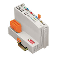
WAGO 750-806 Technical Description (152 pages)
Modular I/O System DeviceNet
Brand:
WAGO
| Category:
I/O Systems
| Size: 2 MB
Table of Contents
Table of Contents
3
1 Important Comments
4
Legal Principles
4
Symbols
5
Font Conventions
6
Number Notation
6
Safety Notes
7
Scope
8
Abbreviation
8
2 The WAGO-I/O-SYSTEM 750
9
System Description
9
Technical Data
10
Manufacturing Number
13
Storage, Consignment and Transport
14
Mechanical Setup
14
Power Supply
22
Grounding
33
Shielding (Screening)
36
Assembly Guidelines / Norms
37
3 Fieldbus Coupler/Controller
38
Fieldbus Coupler 750-306
38
Fieldbus Coupler
39
Description
39
Hardware
40
View
40
Device Supply
41
Fieldbus Connection
42
Display Elements
43
Configuration Interface
44
Hardware Address (MAC ID)
44
Setting the Baud Rate
45
Operating System
45
Process Image
46
Data Exchange
47
Communication Interfaces
48
Memory Areas
48
Addressing
49
Configuration Software
51
Starting up Devicenet Fieldbus Nodes
51
Connecting the PC and Fieldbus Node
51
Setting the MAC ID and Baud Rate
51
Configuration with Static Assembly
52
LED Display
56
Node Status
57
Blink Code
58
Fault Message Via the Blink Code of the I/O LED
58
Supply Voltage Status
59
Technical Data
60
3.2 Fieldbus Controller 750-806
61
Fieldbus Controller 750-806
61
Description
62
Fieldbus Controller
62
Hardware
63
View
63
Device Supply
64
Fieldbus Connection
65
Display Elements
66
Configuration and Programming Interface
67
Operating Mode Switch
67
Hardware Address (MAC ID)
68
Setting the Baud Rate
69
Operating System
70
Start-Up
70
PLC Cycle
70
Process Image
72
Data Exchange
73
Communication Interfaces
74
Memory Areas
74
Addressing
77
Programming the PFC with WAGO-I/O-PRO 32
81
WAGO-I/O-PRO 32 Library Elements
81
IEC 61131-3 Program Transfer
82
Special Devicenet Features of the Controller
85
Connection Via the UCMM Port
85
Offline Connection Set
85
Devicenet Shutdown
85
Dynamic Assembly
85
Change MAC ID by SW
86
Heartbeat
86
Bit-Strobe
86
Configuration Software
87
Starting-Up Devicenet Fieldbus Nodes
87
Connecting the PC and Fieldbus Node
87
Setting the MAC ID and Baud Rate
87
Configuration with Static and Dynamic Assembly
88
LED Display
99
Blink Code
101
Technical Data
103
4 O Modules
105
Description
106
Network Architecture
107
Network Communication
112
Module Characteristics
113
Process Data and Diagnostic Status
114
Configuration / Parametering with the Object Model
116
6 Application in Explosive Environments
139
Foreword
139
Protective Measures
139
Classification Meeting CENELEC and IEC
139
Classifications Meeting the NEC 500
144
Identification
146
Installation Regulations
148
7 Glossary
150
8 Literature List
151
9 Index
152
Advertisement
Related Products
WAGO 750-880/025-000
WAGO 750-881
WAGO 750-843
WAGO 750-8215
WAGO 750-8202/040-001
WAGO 750-8111
WAGO 750-8112 Series
WAGO 750-8112/025-000
WAGO 750-8110
WAGO 750-8202/040-000
WAGO Categories
I/O Systems
Control Unit
Power Supply
Switch
Controller
More WAGO Manuals
Login
Sign In
OR
Sign in with Facebook
Sign in with Google
Upload manual
Upload from disk
Upload from URL