Sign In
Upload
Manuals
Brands
WAGO Manuals
Controller
750-880/025-000
WAGO 750-880/025-000 Manuals
Manuals and User Guides for WAGO 750-880/025-000. We have
1
WAGO 750-880/025-000 manual available for free PDF download: Manual
WAGO 750-880/025-000 Manual (414 pages)
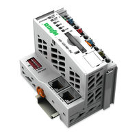
WAGO-I/O-SYSTEM 750 ETHERNET Programmable Fieldbus Controller 10 / 100 Mbit/s; digitale und analoge Signale
Brand:
WAGO
| Category:
Controller
| Size: 10.07 MB
Table of Contents
Table of Contents
5
Table of Contents
3
Table 227: Discrete Output Point
7
Table 192: Message Router
7
Table 280: Input Fieldbus Variable USINT Extended
8
Table of Contents
11
Notes about this Documentation
12
Validity of this Documentation
12
Copyright
12
Symbols
13
Number Notation
15
Font Conventions
15
Table 1: Number Notation
15
Table 2: Font Conventions
15
Important Notes
16
Legal Bases
16
Subject to Changes
16
Personnel Qualifications
16
Use of the 750 Series in Compliance with Underlying Provisions
16
Technical Condition of Specified Devices
17
Safety Advice (Precautions)
18
System Description
20
Figure 1: Fieldbus Node
20
Manufacturing Number
21
Hardware Address (MAC ID)
21
Figure 2: Example of a Manufacturing Number
21
Component Update
22
Storage, Assembly and Transport
22
Assembly Guidelines/Standards
22
Power Supply
23
Isolation
23
Figure 3: Isolation for Standard Couplers/Controllers and Extended ECO Couplers
23
System Supply
24
Connection
24
Figure 4: System Supply for Standard Coupler/Controller and Extended ECO Couplers
24
Alignment
25
Figure 5: System Voltage for Standard Couplers/Controllers and Extended ECO Couplers
25
Table 3: Alignment
25
Field Supply
28
Connection
28
Figure 6: Field Supply (Sensor/Actuator) for Standard Couplers/Controllers and Extended ECO Couplers
28
Fusing
29
Table 4: Power Supply Modules
29
Figure 7: Supply Module with Fuse Carrier (Example 750-610)
30
Figure 8: Removing the Fuse Carrier
30
Figure 9: Opening the Fuse Carrier
31
Figure 10: Change Fuse
31
Figure 12: Fuse Modules for Automotive Fuses, Series 2006
32
Figure 14: Fuse Modules with Pivotable Fuse Carrier, Series 2002
32
Supplementary Power Supply Regulations
33
Figure 15: Power Supply Concept
33
Table 5: Filter Modules for 24-Volt Supply
33
Supply Example
34
Figure 16: Supply Example for Standard Couplers/Controllers and Extended ECO Couplers
35
Power Supply Unit
36
Table 6: WAGO Power Supply Unit
36
Grounding
37
Grounding the DIN Rail
37
Framework Assembly
37
Insulated Assembly
37
Table 7: WAGO Ground Wire Terminals
37
Grounding Function
38
Figure 17: Carrier Rail Contact
38
Grounding Protection
39
Figure 18: Ring-Feeding
39
Shielding (Screening)
40
General
40
Bus Conductors
40
Signal Conductors
40
WAGO Shield (Screen) Connecting System
41
Figure 19: Example WAGO Shield (Screen) Connecting System
41
Figure 20: Application of the WAGO Shield (Screen) Connecting System
41
Device Description
42
Table 8: Compatibility
44
View
45
Figure 21: View ETHERNET Fieldbus Controller
45
Table 9: Legend to the View ETHERNET TCP/IP Fieldbus Controller
46
Connectors
47
Device Supply
47
Fieldbus Connection
47
Figure 22: Device Supply
47
Table 10: RJ-45 Connector and RJ-45 Connector Configuration
48
Display Elements
49
Figure 24: Display Elements
49
Table 11: Display Elements Fieldbus Status
49
Table 12: Display Elements Node Status
49
Table 13: Display Elements Supply Voltage
49
Operating Elements
51
Service Interface
51
Fig. 25: Service Interface for Programming and Configuration
51
Table 14: Service Port
51
Mode Selector Switch
52
Figure 26: Mode Selector Switch (Closed and Open Damper of the Service Port)
52
Table 15: Mode Selector Switch
52
Address Selection Switch
54
Memory Card Slot
54
Figure 27: Address Selection Switch
54
Table 16: Meaning of DIP Switch Positions
54
Inserting a Memory Card
55
Figure 28: Opening the Memory Card Slot, Inserting the SD Card
55
Removing the Memory Card
56
Technical Data
57
Device Data
57
System Data
57
Table 17: Technical Data - Device Data
57
Table 18: Technical Data - System Data
57
Supply
58
Fieldbus MODBUS/TCP
58
Accessories
58
Wire Connection
58
Table 19: Technical Data - Supply
58
Table 20: Technical Data - Fieldbus MODBUS/TCP
58
Table 21: Technical Data - Accessories
58
Table 22: Technical Data Wire Connection
58
Climatic Environmental Conditions
59
Table 23: Technical Data - Climatic Environmental Conditions
59
Mechanical Strength
60
Table 24: Technical Data - Mechanical Strength
60
Approvals
61
Standards and Guidelines
62
Assembly
63
Installation Position
63
Total Extension
63
Assembly Onto Carrier Rail
65
Carrier Rail Properties
65
WAGO DIN Rail
66
Spacing
66
Figure 29: Spacing
66
Table 25: WAGO DIN Rail
66
Assembly Sequence
67
Inserting and Removing Devices
68
Inserting the Fieldbus Coupler/Controller
69
Removing the Fieldbus Coupler/Controller
69
Figure 30: Unlocking Lug of Extended ECO Coupler
69
Inserting I/O Module
70
Figure 31: Insert I/O Module
70
Figure 32: Snap the I/O Module into Place
70
Removing the I/O Module
71
Figure 33: Removing the I/O Module
71
Connect Devices
72
Data Contacts/Internal Bus
72
Figure 34: Data Contacts
72
Power Contacts/Field Supply
73
Figure 35: Example for the Arrangement of Power Contacts
73
Connecting a Conductor to the CAGE CLAMP
74
Figure 36: Connecting a Conductor to a CAGE CLAMP
74
Function Description
75
Operating System
75
Run-Up
75
PFC Cycle
75
Figure 37: Run-Up of the Controller
76
Process Data Architecture
77
Basic Structure
77
Example of an Input Process Image
79
Figure 38: Example of Process Image for Input Data
79
Example of an Output Data Process Image
80
Figure 39: Example of Process Image for Output Data
80
Process Data MODBUS/TCP and Ethernet/Ip
81
Data Exchange
82
Memory Areas
84
Figure 40: Memory Areas and Data Exchange
84
Figure 41: Example Declaration of Remanent Flags by „Var Retain
86
Addressing
87
Figure 42: WAGO I/O Configurator
87
Addressing of I/O Modules
88
Table 26: Data with for I/O Modules
88
Address Ranges
89
Table 27: Breakdown of Address Range
89
Table 28: Address Range Word 0
89
Table 29: Address Range, Word 256 - 511
89
Table 30: Address Range, Word 512 - 1275
90
Table 31: Address Range, Word 1276
90
Table 32: Address Range for Flags
90
Table 33: IEC-61131-3 Address Areas
91
Absolute Addressing
92
Table 34: Absolute Addressing
92
Table 35: Addressing Example
92
Data Exchange between MODBUS/TCP Master and I/O Modules
94
Table 36: Allocation of Digital Inputs and Outputs to Process Data Words in Accordance with the
94
Figure 43: Data Exchange between MODBUS Master and I/O Modules
95
Data Exchange between Ethernet/Ip Master and I/O Modules
96
Data Exchange between PLC Function (CPU) and I/O Modules
97
Figure 44: Data Exchange between PLC Function (CPU) of the PFC and the I/O Modules
97
Data Exchange between Master and PLC Function (CPU)
98
Example of MODBUS/TCP Master and PLC Function (CPU)
98
Application Example
100
Figure 45: Example of Addressing for a Fieldbus Node
100
Memory Card Function
101
System Start (Automatic Loading of Device Settings from the Memory Card)
101
Table 37: Possible Errors on System Start
102
Back-Up Function (Saving Device Settings on the Memory Card)
103
Figure 46: WBM Page „Features
103
Restore Function (Loading of Device Settings from the Memory Card)104
104
Table 38: Possible Errors During the Backup Function
104
Figure 47: WBM Page „Features
105
Table 39: Possible Errors During the Restore Function
106
Inserting a Memory Card During Operation
107
Removing the Memory Card During Operation
108
Table 40: Possible Errors When Removing the Memory Card During Ongoing
108
SPS Access to the File System of the Memory Card
109
Table 41: Possible Errors During SPS Access to the File System of the Memory Card
109
FTP Network Access to the File System of the Memory Card
110
Table 42: Possible Errors During the FTP Network Access on the File System of the
110
Directory Structure
111
Figure 48: Directory Structure Example
111
Table 43: Saved Files in the Directory Structure
111
Commissioning
112
Connecting Client PC and Fieldbus Nodes
113
Allocating the IP Address to the Fieldbus Node
113
Assigning IP Address Via Address Selection Switch
114
Figure 49: Address Selection Switch
115
Assigning IP Address Via DHCP
116
Enable DHCP
116
Disabling DHCP
117
Figure 50: WBM Page "Port
120
Assigning the IP Address with a Bootp Server
121
Note MAC ID
122
Determining IP Addresses
123
Assigning the IP Address and Enable Bootp
124
Disabling Bootp
124
Figure 51: WBM Page "Information
125
Figure 52: WBM Page "Port
126
Reasons for Failed IP Address Assignment
128
Testing the Function of the Fieldbus Node
129
Figure 53: Example for the Function Test of a Fieldbus Node
129
Preparing the Flash File System
131
Synchronizing the Real-Time Clock
133
Figure 54: Example of Real-Time Clock Synchronization in ETHERNET Settings
134
Restoring Factory Settings
136
Programming the PFC Using WAGO-I/O-PRO
137
Figure 55: Dialog Window for Target System Settings
137
Configuration Using the WAGO-I/O-PRO I/O Configurator
139
Configuration Using the "EA-Config.xml" File
142
Figure 57: EA-Config.xml
142
ETHERNET Libraries for WAGO-I/O-PRO
144
Table 44: ETHERNET Libraries for WAGO-I/O-PRO
144
Functional Restrictions and Limits
146
General Information about IEC Tasks
149
Figure 58: Watchdog Runtime Is Less than the Task Runtime
150
Figure 59: Watchdog Runtime Is Greater than the Task Call Interval
150
IEC Task Sequence
151
Overview of most Important Task Priorities
151
Table 45: Task Processing
151
System Events
153
Enabling/Disabling System Events
153
Figure 60: System Events
153
Transfer the IEC Program to the Controller
155
Transfer Via Serial Service Port
156
Figure 61: Dialog Window "Communication Parameters
157
Transfer Via Fieldbus and ETHERNET
159
Configuring Via the Web-Based Management System (WBM)
161
Information
161
Figure 62: WBM Page "Information
162
Table 46: WBM Page "Information
162
Ethernet
163
Table 47: WBM Page "Ethernet
164
Tcp/Ip
166
Figure 64: WBM Page "TCP/IP
166
Table 48: WBM Page „TCP/IP
166
Port
167
Figure 65: WBM Page „Port
167
Table 49: WBM Page "Port
167
Snmp
168
SNMP V1/V2C
169
Figure 66: WBM Page "SNMP
170
Table 50: WBM Page "SNMP
170
Snmp V3
171
Figure 67: WBM Page "SNMP V3
172
Watchdog
173
Figure 68: WBM Page "Watchdog
173
Clock
174
Table 51: WBM Page "Watchdog
174
Figure 69: WBM Page "Clock
175
Table 52: WBM Page "Clock
176
Security
177
Figure 70: WBM Page "Security
178
Table 53: WBM Page "Security
178
Plc
179
Figure 71: WBM Page "PLC
179
Table 54: WBM Page "PLC
180
10.10 Features
182
Figure 72: WBM Page "Features
182
Table 55: WBM Page "Features
182
10.11 I/O Config
183
Figure 73: WBM Page "IO Config
183
Table 56: WBM Page "I/O Configuration
184
10.12 Disk Info
185
Figure 74: WBM Page „Disk Info
185
Table 57: WBM Page "Disk Info
185
10.13 Webvisu
186
Figure 75: WBM Page "Webvisu
187
Diagnostics
188
LED Signaling
188
Evaluating Fieldbus Status
188
Figure 76: Display Elements
188
Table 58: LED Assignment for Diagnostics
188
Table 59: Fieldbus Diagnostics - Solution in Event of Error
189
Evaluating Node Status - I/O LED (Blink Code Table)
190
Table 60: Node Status Diagnostics - Solution in Event of Error
190
Figure 77: Node Status - I/O LED Signaling
191
Figure 78: Error Message Coding
191
Table 61: Blink Code- Table for the I/O LED Signaling, Error Code 1
192
Table 62: Blink Code Table for the I/O LED Signaling, Error Code 2
193
Table 63: Blink Code Table for the I/O LED Signaling, Error Code 3
194
Table 64: Blink Code Table for the I/O LED Signaling, Error Code 4
195
Table 65: Blink Code Table for the I/O LED Signaling, Error Code 5
195
Table 66: Blink Code- Table for the I/O LED Signaling, Error Code 6
196
Table 67: Blink Code Table for the 'I/O' LED Signaling, Error Code 7
196
Table 68: Blink Code Table for the 'I/O' LED Signaling, Error Code 10
197
Table 69: Blink Code Table for the 'I/O' LED Signaling, Error Code 11
197
Table 70: Blink Code Table for the I/O LED Signaling, Error Code 14
198
Usr Led
199
Evaluating Memory Card Status
199
Evaluating Power Supply Status
199
Table 71: Power Supply Status Diagnostics - Solution in Event of Error
199
Fault Behavior
200
Loss of Fieldbus
200
Figure 79: Function Block for Determining Loss of Fieldbus, Independently of
200
Internal Data Bus Failure
202
Fieldbus Communication
203
Implemented Protocols
203
Communication Protocols
203
IP (Internet Protocol)
203
Table 72: IP Packet
203
Table 73: Network Class a
204
Table 74: Network Class B
204
Table 75: Network Class C
204
Table 76: Key Data Class A, B and C
205
Table 77: Class B Address with Field for Subnet Ids
206
Table 78: Subnet Mask for Class a Network
206
Table 79: Subnet Mask for Class B Network
206
Table 80: Subnet Mask for Class C Network
206
Table 81: Example for an IP Address from a Class B Network
206
TCP (Transmission Control Protocol)
208
UDP (User Datagram Protocol)
208
Configuration and Diagnostics Protocols
209
Bootp (Bootstrap Protocol)
209
Table 82: Bootp Options
210
DHCP (Dynamic Host Configuration Protocol)
211
HTTP (Hypertext Transfer Protocol)
213
DNS (Domain Name Systems)
213
Table 83: Meaning of DHCP Options
213
SNTP-Client (Simple Network Time Protocol)
214
FTP-Server (File Transfer Protocol)
214
Table 84: Meaning of the SNTP Parameters
214
SNMP (Simple Network Management Protocol)
215
12.1.2.7.1 MIB II Description
216
Table 85: MIB II Groups
216
12.1.2.7.2 Traps
217
Table 86: Standard Traps
217
Application Protocols
218
MODBUS Functions
219
General
219
Table 87: MODBUS/TCP Header
219
Table 88: Basic Data Types of MODBUS Protocol
220
Table 89: List of the MODBUS Functions in the Fieldbus Controller
221
Use of the MODBUS Functions
222
Figure 80: Use of the MODBUS Functions
222
Description of the MODBUS Functions
223
Table 90: Exception Codes
223
Function Code FC1 (Read Coils)
224
Table 91: Request of Function Code FC1
224
Table 92: Response of Function Code FC1
224
Table 93: Assignment of Inputs
224
Table 94: Exception of Function Code FC1
225
Function Code FC2 (Read Input Discretes)
226
Table 95: Request of Function Code FC2
226
Table 96: Response of Function Code FC2
226
Table 97: Assignment of Inputs
226
Table 98: Exception of Function Code FC2
227
Function Code FC3 (Read Multiple Registers)
228
Table 99: Request of Function Code FC3
228
Table 100: Response of Function Code FC3
228
Table 101: Exception of Function Code FC3
228
Function Code FC4 (Read Input Registers)
229
Table 102: Request of Function Code FC4
229
Table 103: Response of Function Code FC4
229
Table 104: Exception of Function Code FC4
229
Function Code FC5 (Write Coil)
230
Table 105: Request of Function Code FC5
230
Table 106: Response of Function Code FC5
230
Table 107: Exception of Function Code FC5
230
Function Code FC6 (Write Single Register)
231
Table 108: Request of Function Code FC6
231
Table 109: Response of Function Code FC6
231
Table 110: Exception of Function Code FC6
231
Function Code FC11 (Get Comm Event Counter)
232
Table 111: Request of Function Code FC11
232
Table 112: Response of Function Code FC11
232
Table 113: Exception of Function Code FC 11
232
Function Code FC15 (Force Multiple Coils)
233
Table 114: Request of Function Code FC15
233
Table 115: Response of Function Code FC15
233
Table 116: Exception of Function Code FC15
234
Function Code FC16 (Write Multiple Registers)
235
Table 117: Request of Function Code FC16
235
Table 118: Response of Function Code FC16
235
Table 119: Exception of Function Code FC16
235
Function Code FC22 (Mask Write Register)
236
Table 120: Request of Function Code FC22
236
Table 121: Response of Function Code FC22
236
Table 122: Exception of Function Code FC22
236
Function Code FC23 (Read/Write Multiple Registers)
237
Table 123: Request of Function Code FC23
237
Table 124: Response of Function Code FC23
237
Table 125: Exception of Function Code FC23
237
MODBUS Register Mapping
239
Table 126: Register Access Reading (with FC3, FC4 and FC23)
239
Table 127: Register Access Writing (with FC6, FC16, FC22 and FC23)
240
Table 128: Bit Access Reading (with FC1 and FC2)
241
Table 129: Bit Access Writing (with FC5 and FC15)
241
MODBUS Registers
242
Table 130: MODBUS Registers
242
Accessing Register Values
243
Table 131: MODBUS Registers (Continuation)
243
Watchdog Registers
243
Table 132: Register Address 0X1000
244
Table 133: Register Address 0X1001
244
Table 134: Register Address 0X1002
245
Table 135: Register Address 0X1003
245
Table 136: Register Address 0X1004
245
Table 137: Register Address 0X1005
245
Table 138: Register Address 0X1006
245
Table 139: Register Address 0X1007
246
Table 140: Register Address 0X1008
246
Table 141: Register Address 0X1009
246
Table 142: Register Address 0X100A
246
Table 143: Starting Watchdog
247
Table 144: Register Address 0X100B
247
Diagnostic Registers
248
Table 145: Register Address 0X1020
248
Table 146: Register Address 0X1021
248
Configuration Registers
249
Table 147: Register Address 0X1022
249
Table 148: Register Address 0X1023
249
Table 149: Register Address 0X1024
249
Table 150: Register Address 0X1025
249
Table 151: Register Address 0X1028
249
Table 152: Register Address 0X1029
250
Table 153: Register Address 0X102A
250
Table 154: Register Address 0X102B
250
Table 155: Register Address 0X1030
250
Table 156: Register Address 0X1031
250
Table 157: Register Address 0X1050
251
Table 158: Register Address 0X2030
252
Table 159: Register Address 0X2031
252
Table 160: Register Address 0X2032
252
Table 161: Register Address 0X2033
253
Table 162: Register Address 0X2040
253
Table 163: Register Address 0X2041
253
Table 164: Register Address 0X2042
253
Table 165: Register Address 0X2043
253
Firmware Information Registers
254
Table 166: Register Address 0X2010
254
Table 167: Register Address 0X2011
254
Table 168: Register Address 0X2012
254
Table 169: Register Address 0X2013
254
Table 170: Register Address 0X2014
254
Table 171: Register Address 0X2020
254
Table 172: Register Address 0X2021
255
Table 173: Register Address 0X2022
255
Table 174: Register Address 0X2023
255
Constant Registers
256
Table 175: Register Address 0X2000
256
Table 176: Register Address 0X2001
256
Table 177: Register Address 0X2002
256
Table 178: Register Address 0X2003
256
Table 179: Register Address 0X2004
256
Table 180: Register Address 0X2005
256
Table 181: Register Address 0X2006
257
Table 182: Register Address 0X2007
257
Table 183: Register Address 0X2008
257
Table 184: Register Address 0X3000 to 0X5Fff
257
Ethernet/Ip (Ethernet/Industrial Protocol)
258
General
258
Protocol Overview in the OSI Model
259
Table 185: ISO/OSI Reference Model
259
Characteristics of the Ethernet/Ip Protocol Software
260
EDS File
260
General
261
Object Model
261
Class
262
Class Overview
262
Table 186: CIP Common Class
262
Table 193: Message Router
262
Table 187: WAGO Specific Classes
263
Table 230: Analog Input Point
263
Table 271: Module Configuration
263
Table 286: Output Fieldbus Variable USINT
263
Table 295: Input Fieldbus Variable UINT
263
Table 301: Output Fieldbus Variable UINT
263
Explanation of the Table Headings in the Object Descriptions
264
Hex
264
Identity
264
Table 188: Explanation of the Table Headings in the Object Descriptions
264
Table 189: Identity
264
Table 190: Identity
265
Table 191: Identity
265
Hex )
266
Table 194: Message Router
266
Assembly Object (04 Hex )
267
Common Service
267
Table 195: Assembly
267
Table 197: Static Assembly Instances - Instance
268
Table 198: Static Assembly Instances - Instance
268
Table 199: Static Assembly Instances - Instance
268
Table 200: Static Assembly Instances - Instance
268
Table 201: Static Assembly Instances - Instance
269
Table 202: Static Assembly Instances - Instance
269
Table 203: Static Assembly Instances - Instance
269
Table 204: Static Assembly Instances - Instance
270
Table 205: Static Assembly Instances - Instance
270
Table 206: Static Assembly Instances - Instance
270
Table 207: Static Assembly Instances - Instance
270
Connection Manager (06 Hex )
271
Hex )
271
Table 208: Static Assembly Instances - Common Service
271
Hex )
272
Port Class
272
Table 209: Port Class
272
Table 210: Port Class
272
Table 211: Port Class
273
TCP/IP Interface (F5 Hex )
274
Table 212: TCP/IP Interface
274
Ethernet Link (F6 Hex )
275
Table 213: TCP/IP Interface
275
Table 214: TCP/IP Interface
275
Table 215: Ethernet Link
276
Table 216: Ethernet Link
277
Table 217: Ethernet Link
279
Table 218: Ethernet Link
281
Table 219: Ethernet Link
281
Coupler/Controller Configuration
282
Hex )
282
Table 220: Coupler/Controller Configuration
282
Table 221: Coupler/Controller Configuration
282
Discrete Input Point (65 Hex )
284
Discrete Input Point Extended 1 (69 Hex )
284
Table 222: Coupler/Controller Configuration
284
Table 223: Discrete Input Point
284
Table 224: Discrete Input Point
284
Table 225: Discrete Input Point
284
Common Service
284
Discrete Input Point Extended 2 (6D )
285
Table 226: Discrete Input Point Extended 1(69 Hex,) - Class
285
Table 228: Discrete Input Point Extended
285
Table 229: Discrete Input Point Extended 2 (6D Hex) - Class
285
Table 231: Analog Input Point
285
Table 236: Discrete Output Point
285
Common Service
285
Instance 256
285
Instance 511
285
Discrete Input Point Extended 3 (71 Hex )
286
Discrete Output Point (66 Hex )
286
Table 232: Discrete Input Point Extended 3 (71 Hex) - Class
286
Table 233: Discrete Input Point Extended
286
Table 234: Discrete Input Point Extended
286
Table 235: Discrete Output Point (66 Hex) - Class
286
Common Service
286
Hex ) - Class
286
Instance 766
286
Discrete Output Point Extended 1 (6A Hex )
287
Table 237: Discrete Output Point
287
Class
287
Common Service
287
Discrete Output Point Extended 2 (6E Hex )
288
Discrete Output Point Extended
288
Table 244: Discrete Output Point Extended
288
Class
288
Common Service
288
Analog Input Point
289
Class
289
Common Service
289
Hex )
289
Table 245: Discrete Output Point Extended
289
Table 246: Discrete Output Point Extended
289
Table 248: Analog Input Point
289
Table 249: Analog Input Point
289
Analog Input Point Extended 1 (6B )
290
Analog Input Point Extended 2 (6F )
290
Table 250: Analog Input Point Extended
290
Table 251: Analog Input Point Extended
290
Table 252: Analog Input Point Extended
290
Table 253: Analog Input Point Extended
290
Class
290
Common Service
290
Class
291
Common Service
291
Hex )
291
Table 254: Analog Input Point Extended
291
Table 255: Analog Input Point Extended
291
Table 256: Analog Input Point Extended
291
Table 257: Analog Input Point Extended
291
Table 258: Analog Input Point Extended
291
Analog Output Point (68 Hex )
292
Analog Output Point Extended 1 (6C )
292
Table 259: Analog Output Point
292
Table 260: Analog Output Point
292
Table 261: Analog Output Point
292
Table 262: Analog Output Point Extended
292
Class
292
Common Service
292
Instance 1
292
Analog Output Point Extended
293
Class
293
Hex
293
Table 263: Analog Output Point Extended
293
Table 264: Analog Output Point Extended
293
Table 265: Analog Output Point Extended
293
Table 266: Analog Output Point Extended
293
Analog Output Point Extended
294
Hex )
294
Table 267: Analog Output Point Extended
294
Table 268: Analog Output Point Extended
294
Table 269: Analog Output Point Extended
294
Table 270: Analog Output Point Extended
294
Class
294
Module Configuration
295
Module Configuration Extended
295
Hex )
295
Table 272: Module Configuration
295
Table 273: Module Configuration
295
Class
295
Instance 1
295
Table 274: Module Configuration Extended
296
Table 275: Module Configuration Extended
296
Input Fieldbus Variable USINT (A0 )
297
Class
297
Hex )
297
Instance 1
297
Hex )
298
Hex ) - Class
298
Instance 256
298
Table 281: Input Fieldbus Variable USINT Extended
298
Table 282: Input Fieldbus Variable USINT Extended
298
Hex )
299
Instance 511
299
Table 283: Input Fieldbus Variable USINT Extended
299
Table 284: Input Fieldbus Variable USINT Extended
299
Table 285: Input Fieldbus Variable USINT Extended
299
Output Fieldbus Variable USINT
300
Hex
300
Instance 1
300
Table 287: Output Fieldbus Variable USINT
300
Table 288: Output Fieldbus Variable USINT
300
Output Fieldbus Variable USINT Extended
301
Hex
301
Table 289: Output Fieldbus Variable USINT Extended
301
Table 290: Output Fieldbus Variable USINT Extended
301
Table 291: Output Fieldbus Variable USINT Extended
301
Output Fieldbus Variable USINT Extended
302
Hex )
302
Table 292: Output Fieldbus Variable USINT Extended
302
Table 293: Output Fieldbus Variable USINT Extended
302
Input Fieldbus Variable UINT
303
Hex
303
Instance 1
303
Table 296: Input Fieldbus Variable UINT
303
Table 297: Input Fieldbus Variable UINT
303
Input Fieldbus Variable UINT Extended
304
Table 298: Input Fieldbus Variable UINT Extended
304
Table 299: Input Fieldbus Variable UINT Extended
304
Table 300: Input Fieldbus Variable UINT Extended
304
Output Fieldbus Variable UINT
305
Hex
305
Table 302: Output Fieldbus Variable UINT
305
Table 303: Output Fieldbus Variable UINT
305
Output Fieldbus Variable UINT Extended
306
Hex )
306
Table 304: Output Fieldbus Variable UINT Extended
306
Table 305: Output Fieldbus Variable UINT Extended
306
Table 306: Output Fieldbus Variable UINT Extended
306
Input Fieldbus Variable UDINT (AA )
307
Table 307: Input Fieldbus Variable UDINT
307
Table 308: Input Fieldbus Variable UDINT
307
Table 309: Input Fieldbus Variable UDINT
307
Input Fieldbus Variable UDINT Offset
308
Hex )
308
Table 310: Input Fieldbus Variable UDINT Offset
308
Table 311: Input Fieldbus Variable UDINT Offset
308
Table 312: Input Fieldbus Variable UDINT Offset
308
Output Fieldbus Variable UDINT (AC )
309
Table 313: Input Fieldbus Variable UDINT
309
Table 314: Input Fieldbus Variable UDINT (AA Hex ) - Instance 1
309
Table 315: Input Fieldbus Variable UDINT (AA Hex ) - Common Service
309
Output Fieldbus Variable UDINT Offset
310
Hex )
310
Table 316: Output Fieldbus Variable UDINT Offset (AD Hex ) - Class
310
Table 317: Output Fieldbus Variable UDINT Offset (AD Hex ) - Instance 1
310
Table 318: Output Fieldbus Variable UDINT Offset (AD Hex ) - Common Service
310
I/O Modules
311
Overview
311
Process Data Architecture for MODBUS/TCP
312
Channel Digital Input Module with Diagnostics
313
Digital Input Modules
313
Channel Digital Input Modules
313
Table 319: 1 Channel Digital Input Module with Diagnostics
313
Table 320: 2 Channel Digital Input Modules
313
Table 321: 2 Channel Digital Input Module with Diagnostics
313
Channel Digital Input Module with Diagnostics and Output Process Data
314
Channel Digital Input Modules
314
Table 322: 2 Channel Digital Input Module with Diagnostics and Output Process Data
314
Table 323: 4 Channel Digital Input Modules
314
Table 324: 8 Channel Digital Input Modules
314
16 Channel Digital Input Modules
315
Table 325: 16 Channel Digital Input Modules
315
Channel Digital Output Module with Input Process Data
316
Channel Digital Output Modules
316
Table 326: 1 Channel Digital Output Module with Input Process Data
316
Table 327: 2 Channel Digital Output Modules
316
Channel Digital Input Modules with Diagnostics and Input Process Data
317
Table 328: 2 Channel Digital Input Modules with Diagnostics and Input Process Data
317
Table 329: 2 Channel Digital Input Modules with Diagnostics and Input Process
317
Channel Digital Output Modules
318
Channel Digital Output Modules with Diagnostics and Input Process Data
318
Channel Digital Output Module
318
Table 330: 4 Channel Digital Output Modules
318
Table 331: 4 Channel Digital Output Modules with Diagnostics and Input Process Data
318
Table 332: 8 Channel Digital Output Module
318
Channel Digital Output Modules with Diagnostics and Input Process Data
319
Table 333: 8 Channel Digital Output Modules with Diagnostics and Input Process Data
319
Table 334: 16 Channel Digital Output Modules
319
Channel Digital Input/Output Modules
320
Table 335: 8 Channel Digital Input/Output Modules
320
Analog Input Modules
321
Channel Analog Input Modules
321
Channel Analog Input Modules
322
Table 338: 4 Channel Analog Input Modules
322
Analog Output Modules
323
Channel Analog Output Modules
323
Table 339: 2 Channel Analog Output Modules
323
Table 340: 4 Channel Analog Output Modules
323
Specialty Modules
324
Counter Modules
324
Table 341: Counter Modules 750-404, (and All Variations Except of /000-005), 753-404, (and Variation /000-003)
324
Table 342: Counter Modules 750-404/000-005
325
Table 343: Counter Modules 750-638, 753-638
325
Pulse Width Modules
326
Serial Interface Modules with Alternative Data Format
326
Table 344: Pulse Width Modules 750-511, /XXX-XXX
326
Table 345: Serial Interface Modules with Alternative Data Format
326
Serial Interface Modules with Standard Data Format
327
Data Exchange Module
327
SSI Transmitter Interface Modules
327
Table 346: Serial Interface Modules with Standard Data Format
327
Table 347: Data Exchange Module
327
Incremental Encoder Interface Modules
328
Table 348: SSI Transmitter Interface Modules
328
Table 350: Incremental Encoder Interface Modules 750-634
329
Table 351: Incremental Encoder Interface Modules 750-637
329
DC-Drive Controller
330
Table 352: Digital Pulse Interface Modules 750-635
330
Table 353: DC-Drive Controller 750-636
330
Stepper Controller
331
Table 354: Stepper Controller RS 422 / 24 V / 20 Ma 750-670
331
13.2.5.10 RTC Module
332
13.2.5.11 DALI/DSI Master Module
332
Table 355: RTC Module 750-640
332
Table 356: DALI/DSI Master Module 750-641
332
13.2.5.12 Enocean Radio Receiver
333
13.2.5.13 MP Bus Master Module
333
Table 357: Enocean Radio Receiver 750-642
333
Table 358: MP Bus Master Module 750-643
333
Bluetooth ® RF-Transceiver
334
Table 359: Bluetooth ® RF-Transceiver 750-644
334
13.2.5.15 Vibration Velocity/Bearing Condition Monitoring VIB I/O
335
13.2.5.16 KNX/EIB/TP1 Module
335
Table 360: Vibration Velocity/Bearing Condition Monitoring VIB I/O
335
13.2.5.17 AS-Interface Master Module
336
Table 361: KNX/EIB/TP1 Module 753-646
336
Table 362: AS-Interface Master Module 750-655
337
System Modules
338
System Modules with Diagnostics
338
Binary Space Module
338
Table 363: System Modules with Diagnostics 750-610, -611
338
Table 364: Binary Space Module 750-622 (with Behavior Like 2 Channel Digital Input)
338
Table 410: Binary Space Module
338
Process Data Architecture for Ethernet/Ip
339
Digital Input Modules
340
Channel Digital Input Module with Diagnostics
340
Channel Digital Input Modules
340
Table 365: 1 Channel Digital Input Module with Diagnostics
340
Table 366: 2 Channel Digital Input Modules
340
Channel Digital Input Module with Diagnostics
341
Channel Digital Input Module with Diagnostics and Output Process Data
341
Table 367: 2 Channel Digital Input Module with Diagnostics
341
Table 368: 2 Channel Digital Input Module with Diagnostics and Output Process Data
341
Channel Digital Input Modules
342
Table 369: 4 Channel Digital Input Modules
342
Table 370: 8 Channel Digital Input Modules
342
Table 371: 16 Channel Digital Input Modules
342
Digital Output Modules
343
Channel Digital Output Module with Input Process Data
343
Table 372: 1 Channel Digital Output Module with Input Process Data
343
Channel Digital Output Modules
344
Channel Digital Input Modules with Diagnostics and Input Process Data
344
Table 373: 2 Channel Digital Output Modules
344
Table 374: 2 Channel Digital Input Modules with Diagnostics and Input Process Data
344
Channel Digital Output Modules
345
Channel Digital Output Modules with Diagnostics and Input Process Data
345
Table 375: 2 Channel Digital Input Modules with Diagnostics and Input Process
345
Table 376: 4 Channel Digital Output Modules
345
Table 377: 4 Channel Digital Output Modules with Diagnostics and Input Process Data
345
Channel Digital Output Module
346
Channel Digital Output Modules with Diagnostics and Input Process Data
346
Table 378: 8 Channel Digital Output Module
346
Table 379: 8 Channel Digital Output Modules with Diagnostics and Input Process Data
346
16 Channel Digital Output Modules
347
Channel Digital Input/Output Modules
347
Table 380: 16 Channel Digital Output Modules
347
Table 381: 8 Channel Digital Input/Output Modules
347
Analog Input Modules
348
Channel Analog Input Modules
348
Table 382: 1 Channel Analog Input Modules
348
Channel Analog Input Modules
349
Table 336: 1 Channel Analog Input Modules
349
Table 337: 2 Channel Analog Input Modules
349
Table 383: 2 Channel Analog Input Modules
349
Table 384: 4 Channel Analog Input Modules
349
Analog Output Modules
350
Channel Analog Output Modules
350
Table 385: 2 Channel Analog Output Modules
350
Table 386: 4 Channel Analog Output Modules
350
Specialty Modules
351
Counter Modules
351
Table 387: Counter Modules 750-404, (and All Variations Except of /000-005), 753-404, (and Variation /000-003)
351
Table 388: Counter Modules 750-404/000-005
352
Pulse Width Modules
353
Serial Interface Modules with Alternative Data Format
353
Table 389: Counter Modules 750-638, 753-638
353
Table 390: Pulse Width Modules 750-511, /XXX-XXX
353
Serial Interface Modules with Standard Data Format
354
Table 391: Serial Interface Modules with Alternative Data Format
354
Table 392: Serial Interface Modules with Standard Data Format
354
Data Exchange Module
355
SSI Transmitter Interface Modules
355
Table 393: Data Exchange Module
355
Table 394: SSI Transmitter Interface Modules
355
Incremental Encoder Interface Modules
356
Table 395: SSI Transmitter Interface I/O Modules with an Alternative Data
356
Table 396: Incremental Encoder Interface Modules 750-631/000-004, -010, -011
356
Table 397: Incremental Encoder Interface Modules 750-634
357
Table 398: Incremental Encoder Interface Modules 750-637
357
DC-Drive Controller
358
Table 399: Incremental Encoder Interface Modules 750-635, 750-635
358
Table 400: DC-Drive Controller 750-636
358
Steppercontroller
359
Table 401: Steppercontroller RS 422 / 24 V / 20 Ma 750-670
359
13.3.5.10 RTC Module
360
Table 402: RTC Module 750-640
360
13.3.5.11 DALI/DSI Master Module
361
13.3.5.12 Enocean Radio Receiver
361
Table 403: DALI/DSI Master Module 750-641
361
Table 404: Enocean Radio Receiver 750-642
361
13.3.5.13 MP Bus Master Module
362
Bluetooth ® RF-Transceiver
362
Table 405: MP Bus Master Module 750-643
362
13.3.5.15 Vibration Velocity/Bearing Condition Monitoring VIB I/O
363
Table 406: Bluetooth ® RF-Transceiver 750-644
363
Table 407: Vibration Velocity/Bearing Condition Monitoring VIB I/O
363
13.3.5.16 AS-Interface Master Module
364
Table 408: AS-Interface Master Module 750-655
364
System Modules
365
System Modules with Diagnostics
365
Binary Space Module
365
Table 409: System Modules with Diagnostics 750-610, -611
365
Application Examples
366
Test of MODBUS Protocol and Fieldbus Nodes
366
Visualization and Control Using SCADA Software
366
Figure 81: Example SCADA Software with MODBUS Driver
368
Table 411: MODBUS Table and Function Codes
368
Use in Hazardous Environments
369
Identification
370
For Europe According to CENELEC and IEC
370
Figure 82: Example for Lateral Labeling of Bus Modules
370
Figure 83: Printing on Text Detail in Accordance with CENELEC and IEC
370
Table 412: Description of Printing on
370
Figure 84: Example of Side Marking of Ex I and IEC Ex I Approved I/O Modules
371
Figure 85: Inscription Text Detail Acc. CENELEC and IEC
371
Table 413: Description of the Inscription
372
For America According to NEC 500
373
Figure 86: Example for Lateral Labeling of Bus Modules
373
Figure 87: Printing on Text Detail in Accordance with NEC
373
Table 414: Description of Printing on
373
Installation Regulations
374
Table 415: VDE Installation Regulations in Germany
374
Table 416: Installation Regulations in USA and Canada
374
Special Conditions for Safe Operation of the ATEX and IEC Ex (Acc. DEMKO 08 ATEX 142851X and Iecex PTB 07.0064)
375
Special Conditions for Safe Use (ATEX Certificate TÜV 07 ATEX 554086 X)
376
Special Conditions for Safe Use (IEC-Ex Certificate TUN 09.0001
377
Ansi/Isa 12.12.01
378
Appendix
379
MIB II Groups
379
System Group
379
Table 417: MIB II - System Group
379
Interface Group
380
Table 418: MIB II - Interface Group
380
IP Group
382
Table 419: MIB II - IP Group
382
Iproute Table Group
383
Table 420: MIB II - Iproute Table Group
383
ICMP Group
384
Table 421: MIB II - ICMP Group
384
TCP Group
385
Table 422: MIB II - TCP Group
385
UDP Group
386
Table 423: MIB II - UDP Group
386
SNMP Group
387
Table 424: MIB II - SNMP Group
387
WAGO MIB Groups
388
Company Group
388
Product Group
388
Table 425: WAGO MIB - Company Group
388
Table 426: WAGO MIB - Product Group
388
Versions Group
389
Table 427: WAGO MIB - Versions Group
389
Real-Time Clock Group
390
Table 428: WAGO MIB - Real Time Clock Group
390
Ethernet Group
391
Actual Error Group
391
Table 429: WAGO MIB - Ethernet Group
391
Table 430: WAGO MIB - Actual Error Group
391
PLC Project Group
392
Table 431: WAGO MIB - PLC Project Group
392
Http Group
393
Ftp Group
393
Table 432: WAGO MIB - Http Group
393
Table 433: WAGO MIB - Ftp Group
393
16.2.10 Sntp Group
394
16.2.11 Snmp Group
394
Table 434: WAGO MIB - Sntp Group
394
Table 435: WAGO MIB - Snmp Group
394
16.2.12 Snmp Trap String Group
396
Table 436: WAGO MIB - Snmp Trap String Group
396
16.2.13 Snmp User Trap String Group
397
16.2.14 Plc Connection Group
397
Table 437: WAGO MIB - Snmp User Trap String Group
397
Table 438: WAGO MIB - Plc Connection Group
397
16.2.15 Modbus Group
398
Table 439: WAGO MIB - Modbus Group
398
16.2.16 Ethernet IP Group
399
16.2.17 Process Image Group
399
Table 440: WAGO MIB - Ethernet IP Group
399
Table 441: WAGO MIB - Process Image Group
399
16.2.18 Plc Data Group
400
Table 442: WAGO MIB - Plc Data Group
400
List of Figures
401
List of Tables
403
Advertisement
Advertisement
Related Products
WAGO 750-880
WAGO 750-806
WAGO 750-881
WAGO 750-843
WAGO 750-8215
WAGO 750-872
WAGO 750-8202/040-000
WAGO 750-8202/040-001
WAGO 750-636/000-800
WAGO 750-636-025-000
WAGO Categories
I/O Systems
Control Unit
Power Supply
Switch
Controller
More WAGO Manuals
Login
Sign In
OR
Sign in with Facebook
Sign in with Google
Upload manual
Upload from disk
Upload from URL