Sign In
Upload
Manuals
Brands
Honeywell Manuals
Controller
Touchpoint Plus
Honeywell Touchpoint Plus Manuals
Manuals and User Guides for Honeywell Touchpoint Plus. We have
9
Honeywell Touchpoint Plus manuals available for free PDF download: Technical Handbook, User Manual, Quick Start Manual
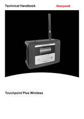
Honeywell Touchpoint Plus Technical Handbook (158 pages)
Brand:
Honeywell
| Category:
Gas Detectors
| Size: 3.52 MB
Table of Contents
5
Table of Contents
9
Chapter 1. Important Information
9
Regulatory Approval Markings
9
Additional Product Markings
9
TPPL Mandatory Warning
10
TPPL General Warnings
11
TPPL General Cautions
11
How to Use This Manual
11
Intended Readers
11
Conventions Used
12
Associated Manuals
13
Chapter 2. Safety Hazards, Warnings and Cautions
13
Safety
13
Warnings and Cautions
14
Safety Hazards
16
Location and Description of Warning Labels
16
Safety Warning Labels
17
Electrical Hazards
17
General Safety Precautions
17
Component Testing and Replacement
18
Good Practice
18
Lithium Battery Hazard
19
Product Compliance
20
Training of Personnel
20
Conditions Satisfying Local, National and International Safety Regulations
20
Approved Maintenance and Servicing Procedures
20
Security Guide
20
Firmware and EEPROM Update
21
Chapter 3. System General Description
23
How to Open and Close the Enclosure
24
Equipment Specification
24
Power Requirements (Controller Unit Only)
24
Maximum Power Consumption Calculations
24
Power Supply (SMPS RS 150 24) Electrical Ratings
25
Weights
25
Dimensions
25
Ambient Operating Temperature
25
Overall Ambient Operating Humidity
25
Storage Conditions (Without Batteries)
25
Storage Conditions (With Batteries)
26
Touchpoint Plus Packaging
26
Packaging Components for Return to Manufacturer
26
Disposal (WEEE Directive)
26
TPPL Construction
26
TPPL Basic Control Unit
27
TPPL Expansion Unit
27
TPPL DIP Switches
28
Chapter 4. System Mechanical Installation
28
Wall Mounting Requirements
30
Chapter 5. Electrical Power Connection and Interfacing
30
Power Connection
31
AC Power Supply
31
Regional Power Cable Colours
32
DC Power Supply
32
Backup Battery Pack
33
Cabling and Connection Requirements
33
AC Mains Voltage Power Cables
33
DC Power Cables
33
Field Device Cables
34
Optional Expansion Unit Connection
35
Main Module Connections
36
Expansion Module Power Connections
37
TPPL DIP Switches
37
Ethernet Connection (Option)
38
Module / Field Device Connections
39
Ma Input Module Connections
42
MV Input Module Connections
43
MV Input Module Connections
44
Dual Input Module Connections
45
Ma Output Module Connections
46
Relay Output Module Connections
47
Modbus Remote Terminal Unit (RTU) and Transmission Control Protocol (TCP) Connections
49
Modbus Configuration
50
Chapter 6. Commissioning
50
Menu Structure
50
The Information Menu
50
Information Menu
51
The Configuration Menu
52
The Maintenance Menu
52
System Test Menu
53
First Time Switch On
53
Home Screen Menu Icons
54
Logging In/Out
54
How to Log in
54
How to Log Out
54
Password Rules
55
How to Change a Password
55
Forgotten Passwords
56
Date, Time and Language Settings
56
How to Set or Change Date, Time and Language Settings
56
Service Contact Settings
57
Touch Panel Configuration
57
How to Change the Backlight Timeout and Brightness
57
How to Calibrate the Touch Panel
57
Latching Alarms
60
Remote Reset / Acknowledge / Inhibit Switch Options
60
Data Logging
60
To Set or Change Data Logging
61
TPPL TCP/IP Address
61
Network Settings for WEB and MODBUS TCP
62
Modbus RTU Settings
63
Commission Input / Output Modules
63
Channel Configuration
63
Introduction
64
Configuring a Channel (Ma Input and MV Input Channels)
65
Editing a Configured Channel
65
Editing Ma Input Channel Settings
69
Editing MV Input Channel Settings
71
Editing Relay Output Channel Settings
73
Editing Ma Output Channel Settings
75
Calibrating Input Channels
75
Adjusting the MV Sensor Baseline
75
Calibrating a MV Input Channel
77
Calibrating a Ma Input Channel
79
Backing Up the Configuration Settings
79
How to Back Up the Configuration
80
How to Restore the Configuration
81
Chapter 7. Touchpoint Plus User Guide
81
User Interface General
82
Touchscreen
82
Switching On and Off
83
Menu Items and Access Levels
85
Navigation Active Access Level Icons
85
SD Card Usage
85
User / Component Matrix
86
Checking the Capacity of the SD Card
86
Inserting or Replacing SD Cards
87
Normal Operation (Safety Functions)
88
Operating Overview
88
Touchscreen
88
User Interface Screen
90
Navigating the Channel Detail Screens
91
Navigation Active Events and Filtering
92
Navigation Menu
93
Responding to Alarms
93
Remote Reset and Acknowledge Switches
93
View Active Alarms
93
Accept or Acknowledge an Active Alarm
94
Reset a Latched Alarm
94
Event Information
94
Viewing E V E N T Information
94
Accepting / Acknowledging Active Events
95
Resetting Latched Events
95
Inhibiting Channels
95
To Inhibit Input Channels
95
To Clear Inhibits
96
To Change Inhibit Timeouts
96
Viewing Input Channels and Input Details
98
Viewing Output Channels
99
Viewing T H E Trend Graph
100
Viewing and Exporting Event History
100
To View the Event History
100
To Export the Event History
100
Accessing the System Information and Service Contact Details
100
System State and System Failure Relays
101
Monitoring TPPL Via the Optional Web Interface
101
Web Interface Configuration
102
Web Interface Channel List View
102
Web Interface Channel Summary View
102
Web Interface Connection Failed Dialog
103
Web Interface Navigation
103
Web Interface Information Menu Showing Event History
104
Chapter 8. Routine Maintenance and Scheduled Testing
104
Routine Maintenance
104
Periodic Checks
105
Routine Testing
105
Exercising the Audio/Visual Alarms
106
Exercising the Relays
106
Checking the Ma Outputs
107
Calibrating MV Input Channels
109
Periodic Scheduled Testing
109
Introduction
110
Field Inputs Test
110
Cause and Effect Test
111
LCD, LED and Buzzer Test
111
Reaction and Response Time Test
112
Chapter 9. Repairs, Replacements and Upgrades
112
How to Decommission and Remove a Serviceable I/O Module
112
To Remove a Serviceable Module
113
How to Replace a Faulty I/O Module
113
To Replace a Faulty Module
114
How to Add a New I/O Module
114
To Add a New Module
115
How to Update the Sensor Catalogue
116
How to Backup / Restore the System Configuration
116
To Create a Backup File
117
To Restore the Configuration From a Backup File
118
How to Update Firmware
118
How to Check Firmware Compatibility
119
How to Update the Firmware
120
Back Up Battery Maintenance
120
Recommended Backup Battery Maintenance
120
How to Replace the Backup Battery
121
Return to Factory Default Settings
121
To Reset the Touchpoint Plus to Its Factory Default Settings
121
Battery On/Off Switch and Battery Connector
122
Chapter 10. Troubleshooting
122
Calling for Technical Support
123
Chapter 11. Technical Specifications
123
Environmental
123
User Interface and Main Module
124
I/O Modules
124
Ma Input Module
124
MV Input Module
124
Dual Input Module
125
Ma Output Module
125
Relay Output Module
125
Expansion Module
125
Power Supplies
125
External Supplies
126
Backup Battery
126
Enclosures
126
Wall Mount Enclosure
127
Chapter 12. Certifications
127
EU Declaration of Conformity
127
National and International Certificates of Compliance
128
European Performance Approval (DEKRA Testing and Certification Gmbh) for Systems
128
Special Conditions for Use When Used for Measurement of Flammable Gases
129
Special Conditions for Use When Used for Measurement of Toxic Gases or Oxygen129
129
Special Conditions for Software Update
130
Chapter 13. Replacement Parts and Optional Extras
130
Spare Parts
131
Publications
133
Chapter 14. TPPL Configuration Code
133
TPPL Configuration P/N Code Chart (Example)
134
Chapter 15. Icon Glossary
134
Configuration Menu
134
Maintenance Menu
135
Chapter 16. Compatible Sensors
135
TPPL Gas Detectors
136
Chapter 17. Configurable Parameter Reference Guide
147
Chapter 18. Event Codes
155
Chapter 19. List of Figures
155
Ma Output Module Connections
Advertisement
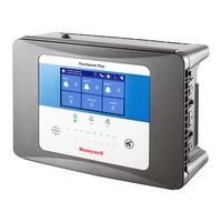
Honeywell Touchpoint Plus Technical Handbook (126 pages)
Brand:
Honeywell
| Category:
Controller
| Size: 7.55 MB
Table of Contents
4
Table of Contents
7
Chapter 1 - Important Safety Information
9
Cautions
9
Intended Readers
9
Conventions Used
9
Associated Manuals
10
Chapter 2 - Safety Hazards, Warnings and Cautions
10
Safety
10
Warnings and Cautions
11
Safety Hazards
13
Location and Description of Warning Labels
13
Safety Warning Labels
13
Figure 1. Quickstart Guide Label (Not to Scale)
13
Figure 2. SMPS Voltage Warning Label (Removed During Installation)
13
Figure 3. Protective Earth (Ground) Point
13
Figure 4. Equipment Earth (Ground) Point
14
Electrical Hazards
14
General Precautions
14
Component Testing and Replacement
15
Antistatic Precautions
15
Good Practice
15
Lithium Battery Hazard
16
Product Compliance
17
Conditions of Use
17
Training of Personnel
17
Conditions Satisfying Local, National and International Safety Regulations
17
Due Authorisation
17
Approved Maintenance and Servicing Procedures
17
Security Guide
18
Chapter 3 - System General Description
18
Figure 6. Touchpoint Plus Wireless Wall-Mounted Controller
19
Figure 7. Typical Installation Options
19
Figure 8. Controller Exploded View
20
Equipment Specification
20
Power Requirements
20
System Power Calculations
21
Weights
21
Dimensions
21
Ambient Operating Temperature
21
Overall Ambient Operating Humidity
21
Storage Conditions (Without Batteries)
21
Storage Conditions (With Batteries)
22
Construction
22
Touchpoint Plus Wireless Packaging
22
Packaging Components for Return to Manufacturer
22
Disposal (WEEE Directive)
23
System Construction
23
Figure 9. System Layout before Installation
24
Chapter 4 - System Mechanical Installation
25
How to Open and Close the Enclosure
25
Figure 10. Undoing the Security Screws and Opening the Enclosure
26
Wall Mounting Requirements
26
Figure 11. Installation Clearance Measurements
26
Figure 12. Wall Mounting Points
26
Figure 13. Wall Mounting Plate Option
27
Wall Mount Fixings
28
Figure 14. Fixing Orientation When Using the Optional Mounting Plate
29
Chapter 5 - Electrical Power Connection and Interfacing
29
Power Connection
30
AC Power Supply
30
Figure 15. Switched Mode Power Supply (SMPS) Connections
30
Regional Power Cable Colours
31
DC Power Supply
31
Backup Battery Pack
31
Figure 16. Connections for DC 24 V Supply
32
Cabling Requirements
32
AC Mains Voltage Power Cables
32
DC Power Cables
32
Field Device Cables
33
Main Module Connections
34
Figure 17. Dedicated Alarm Circuit Connections
34
Figure 18. Optional Remote Reset and Inhibit Switch Connections
35
Ma Input Module Connections
35
Figure 19. Three Wire Device Powered By a Ma Input Module
36
Figure 20. Three Wire Device Powered By an External Source
36
Figure 21. Two Wire Device Powered By a Ma Input Module
36
Figure 22. Two Wire Device Powered By an External Source
37
Grounding
37
Figure 23. Two Wire Device Barrier Device Powered By a Ma Input Module
37
Figure 24. Grounding for Screened Cable with Armour and with Metal Junction Box and Sensor
37
Figure 25. Grounding for Screened Cable, No Armour, with Metal Junction Box and Sensor
38
Figure 26. Grounding for Screened and Armoured Cable with Plastic Junction Box and Sensor
38
Figure 27. Grounding for Screened Cable with Plastic Junction Box and Sensor
38
Figure 28. Grounding for Antenna
39
Wireless Module Connections
39
Figure 29. Grounding for Antenna Extension
40
Antenna Installation
40
Antenna Extension Connection
41
FA324 Connection
41
Figure 30. FA324 Connection
42
Figure 31. FA324 Connector Cable 1 Wiring
42
Figure 32. FA324 Connector Cable 2 Wiring
43
Raemet Wind Sensor Connection
44
Figure 33. Raemet Wind Sensor Connection
45
Relay Output Module Connections
46
Figure 34. Relay States
47
Chapter 6 - Touchpoint Plus Wireless Operating Instructions
47
User Interface General
47
Figure 35. Touchpoint Plus Wireless Controller User Interface
48
Menu Items and Access Levels
51
Touchscreen (Colour Resistive)
51
SD Card
52
Normal Operation (Safety Functions)
52
Overview - Touchscreen Interface
52
User Interface Screen
54
Navigation - Active Events and Filtering
55
Navigation - Menu
56
Navigation - Active Access Level Icons
56
Alarms
56
View Active Alarms
57
Acknowledge an Active Alarm
57
Reset a Latched Alarm
58
Faults and Warnings
58
View Faults and Warnings
58
Acknowledging an Active Fault or Warning
58
Reset a Latched Fault or Warning
59
Inhibit
59
Viewing Input Channels and Input Details
61
Viewing the Trend Graph
61
Viewing Event History and Export
61
Checking the Capacity of the SD Card
62
Accessing the System Information and Service Contact Details
62
System State Relays
63
Chapter 7 - Commissioning
63
Introduction
63
First Time Switch On
64
Date, Time and Language Settings
64
How to Set or Change Date, Time and Language Settings
64
Program Passwords
65
Commission Input / Output Modules
66
Channel Configuration
66
Introduction
67
Wireless Network Setting (Mesh Network)
68
Configuring a Channel
69
Editing a Configured Channel
70
Configuring Wireless Inputs
71
Configuring Relay Output Channels
74
Configuring Wireless Output
75
Programming FA324
78
Data Logging
79
Touch Panel Configuration
79
How to Calibrate the Touch Panel
79
Service Contact Settings
80
Back Up Configuration
81
Calibrate Ma Input Channel Loops
81
Calibrate Wireless Input Channel
82
Chapter 8 - Maintenance
82
Routine Maintenance
82
Weekly Checks
83
Exercising the Relays
83
Exercising Audio/Visual Alarm
83
LCD Test
83
LED and Buzzer Test
83
Mesh Network Test
84
Testing the Touchpoint Plus Wireless System
84
Introduction
85
How to Replace a Faulty I/O Module
86
How to Add a New I/O Module
87
How to Remove or Decommission an I/O Module
87
How to Update the Sensor Catalogue
88
How to Backup / Restore Configuration
89
How to Update Firmware
89
How to Check System Compatibility
89
How to Update the Firmware
90
How to Change the SD Card
90
Figure 36. SD Card Location
91
Back Up Battery Maintenance
91
Recommended Scheduled Maintenance
91
How to Replace the Battery Pack
92
Return to Factory Setting
92
Figure 37. Battery On/Off Switch and Battery Connector
93
Chapter 9 - Troubleshooting
93
Calling for Technical Support
94
Chapter 10 - Technical Specifications
94
Environmental
94
User Interface and Main Module
95
I/O Modules
95
Ma Input Module
95
Relay Output Module
95
Wireless Module
96
Power Supplies
96
External Supplies
96
Backup Battery
96
Enclosures
96
Wall Mount Enclosure
97
Chapter 11 Certifications
97
EC Declaration of Conformity
98
National and International Certificates of Compliance
99
Chapter 12 Replacement Parts and Optional Extras
101
Chapter 13 - Glossary of Icons
105
Chapter 14 Configurable Parameter Reference Guide
116
Chapter 15 Event Codes
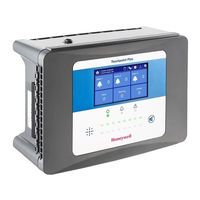
Honeywell Touchpoint Plus Technical Handbook (99 pages)
Brand:
Honeywell
| Category:
Controller
| Size: 5.34 MB
Table of Contents
4
Table of Contents
7
Chapter 1 - Important Safety Information
9
Cautions
9
Intended Readers
10
Conventions Used
10
Associated Manuals
11
Chapter 2 - Safety Hazards, Warnings and Cautions
11
Safety
11
Warnings and Cautions
12
Safety Hazards
14
Location and Description of Warning Labels
14
Safety Warning Labels
14
Figure 1. Quickstart Guide Label (Not to Scale)
14
Figure 2. SMPS Voltage Warning Label (Removed During Installation)
14
Figure 3. Protective Earth (Ground) Point
14
Figure 4. Equipment Earth (Ground) Point
15
Electrical Hazards
15
General Precautions
15
Component Testing and Replacement
16
Antistatic Precautions
16
Good Practice
16
Lithium Battery Hazard
17
Product Compliance
18
Conditions of Use
18
Training of Personnel
18
Conditions Satisfying Local, National and International Safety Regulations
18
Due Authorisation
18
Approved Maintenance and Servicing Procedures
19
Chapter 3 - System General Description
19
Figure 6. Touchpoint Plus Wall-Mounted Controller
19
Figure 7. Typical Installation Options
20
Figure 8. TPPL Controller Exploded View
21
Equipment Specification
21
Power Requirements
21
Power Supply (SMPS RS-150-24) Electrical Ratings
21
System Power Calculations
22
Weights
22
Dimensions
22
Ambient Operating Temperature
22
Overall Ambient Operating Humidity
22
Storage Conditions (Without Batteries)
22
Storage Conditions (With Batteries)
23
Touchpoint Plus Packaging
23
Packaging Components for Return to Manufacturer
23
Disposal (WEEE Directive)
23
System Construction
23
Figure 9. System Layout before Installation
24
Chapter 4 - System Mechanical Installation
25
How to Open and Close the Enclosure
25
Figure 10. Undoing the Security Screws and Opening the Enclosure
26
Wall Mounting Requirements
26
Figure 11. Installation Clearance Measurements
26
Figure 12. Wall Mounting Template
26
Figure 13. Wall and Plate Mounting Points
27
Wall Mount Fixings
27
Figure 14. Fixing Orientation When Using the Optional Mounting Plate
28
Chapter 5 - Electrical Power Connection and Interfacing
28
Power Connection
29
AC Power Supply
29
Figure 15. Switched Mode Power Supply (SMPS) Connections
29
Regional Power Cable Colours
30
DC Power Supply
30
Backup Battery Pack
30
Figure 16. Connections for DC 24 V Supply
31
Cabling Requirements
31
AC Mains Voltage Power Cables
31
DC Power Cables
31
Field Device Cables
32
Optional Expansion Unit Connection (Available Late 2015)
32
Figure 17. Connecting the Touchpoint Plus and Optional Expansion Unit to a Mains Supply
33
Main Module Connections
34
Figure 18. Dedicated Alarm Circuit Connections
34
Figure 19. Optional Remote Reset and Inhibit Switch Connections
35
Ma Input Module Connections
35
Figure 20. Three Wire Device Powered By a Ma Input Module
36
Figure 21. Three Wire Device Powered By an External Source
36
Figure 22. Two Wire Device Powered By a Ma Input Module
36
Figure 23. Two Wire Device Powered By an External Source
37
Figure 24. Two Wire Device Barrier Device Powered By a Ma Input Module
37
Figure 25. Grounding for Screened Cable with Armour and with Metal Junction Box and Sensor
37
Figure 26. Grounding for Screened Cable, No Armour, with Metal Junction Box and Sensor
38
Figure 27. Grounding for Screened and Armoured Cable with Plastic Junction Box and Sensor
38
Figure 28. Grounding for Screened Cable with Plastic Junction Box and Sensor
39
MV Input Module Connections
39
Figure 29. Catalytic Detector Connections
40
Ma Output Module Connections (Each)
40
Figure 30. Ma Output Module Connections
40
Ma Output Module Connections
41
Touchpoint Plus Technical Handbook
41
Relay Output Module Connections
42
Figure 31. Relay States
43
Chapter 6 - Touchpoint Plus Operating Instructions
43
User Interface General
43
Figure 32. Touchpoint Plus Controller User Interface
44
Menu Items and Access Levels
46
Touchscreen (Colour Resistive)
46
SD Card
46
User Matrix
47
Normal Operation (Safety Functions)
47
Overview - Touchscreen Interface
47
User Interface Screen
48
Navigation - Inputs and Outputs Screens
49
Navigation - Active Events and Filtering
50
Navigation - Menu
51
Navigation - Active Access Level Icons
51
Alarms
51
View Active Alarms
51
Acknowledge an Active Alarm
52
Reset a Latched Alarm
52
Faults and Warnings
52
View Faults and Warnings
53
Acknowledging an Active Fault or Warning
53
Reset a Latched Fault or Warning
53
Inhibit
54
Viewing Input Channels and Input Details
55
Viewing Output Channels
55
Viewing Th E Trend Graph
56
To View Event History and Export
56
Checking the Capacity of the SD Card
56
Accessing the System Information and Service Contact Details
56
System State Relays
57
Chapter 7 - Commissioning
57
Introduction
57
First Time Switch On
58
Date, Time and Language Settings
58
How to Set or Change Date, Time and Language Settings
58
Program Passwords
59
Commission Input / Output Modules
59
Channel Configuration
59
Introduction
60
Configuring a Channel (Ma Input and MV Input Channel)
61
Editing a Configured Channel
61
Editing Ma Input Channel Settings (In Pictures)
62
Editing MV Input Channel Settings (In Pictures)
63
Editing Relay Output Channel Settings
64
Editing Relay Output Channel Settings (In Pictures)
65
Data Logging
65
Touch Panel Configuration
65
How to Calibrate the Touch Panel
66
Service Contact Settings
66
Back Up Configuration
67
Calibrating MV Input Channels
67
Adjusting the MV Sensor Baseline
67
Calibrating a MV Sensor Channel
68
Calibrate Ma Input Channel Loops
69
Chapter 8 - Maintenance
69
Routine Maintenance
69
Weekly Checks
70
Exercising the Audio/Visual Alarm
71
Testing the Touchpoint Plus System
71
Introduction
71
Field Inputs Test
72
Cause and Effect Test
73
How to Replace a Faulty I/O Module
74
How to Add a New I/O Module
74
How to Decommission and Remove an I/O Module
75
How to Update the Sensor Catalogue
75
How to Backup / Restore Configuration
76
How to Update Firmware
76
How to Check System Compatibility
76
How to Update the Firmware
77
How to Change the SD Card
77
Figure 33. SD Card Location
78
How to Calibrate MV Input Channels
80
Back Up Battery Maintenance
80
Recommended Scheduled Maintenance
80
How to Replace the Battery Pack
81
Return to Factory Default Settings
81
Figure 34. Battery On/Off Switch and Battery Connector
82
Chapter 9 - Troubleshooting
82
Calling for Technical Support
83
Chapter 10 - Technical Specifications
83
Environmental
83
User Interface and Main Module
84
I/O Modules
84
Ma Input Module
84
MV Input Module
84
Ma Output Module
85
Relay Output Module
85
Power Supplies
85
External Supplies
85
Backup Battery
86
Enclosures
86
Wall Mount Enclosure
87
Chapter 11 - Certifications
87
EC Declaration of Conformity
87
National and International Certificates of Compliance
88
Chapter 12 - Replacement Parts and Optional Extras
89
Chapter 13 - TPPL Configuration Information
90
Chapter 14 - Glossary of Icons
92
Chapter 15 - Compatible Sensors
92
TPPL Gas Detectors
93
Chapter 16 - Configurable Parameter Reference Guide
96
Chapter 17 - Fault Codes
Advertisement
Honeywell Touchpoint Plus Technical Handbook (102 pages)
Brand:
Honeywell
| Category:
Controller
| Size: 5.64 MB
Table of Contents
4
Table of Contents
7
Chapter 1 - Important Safety Information
9
Cautions
9
Intended Readers
10
Conventions Used
10
Associated Manuals
11
Chapter 2 - Safety Hazards, Warnings and Cautions
11
Safety
11
Warnings and Cautions
12
Safety Hazards
14
Location and Description of Warning Labels
14
Safety Warning Labels
14
Figure 1. Quickstart Guide Label (Not to Scale)
14
Figure 2. SMPS Voltage Warning Label (Removed During Installation)
14
Figure 3. Protective Earth (Ground) Point
14
Figure 4. Equipment Earth (Ground) Point
15
Electrical Hazards
15
General Precautions
15
Component Testing and Replacement
16
Antistatic Precautions
16
Good Practice
16
Lithium Battery Hazard
17
Product Compliance
17
Training of Personnel
17
Conditions Satisfying Local, National and International Safety Regulations
18
Due Authorisation
18
Approved Maintenance and Servicing Procedures
19
Chapter 3 - System General Description
19
Figure 6. Touchpoint Plus Wall-Mounted Controller
19
Figure 7. Typical Installation Options
20
Figure 8. TPPL Controller Exploded View
21
Equipment Specification
21
Power Requirements
21
Power Supply (SMPS RS-150-24) Electrical Ratings
21
System Power Calculations
22
Weights
22
Dimensions
22
Ambient Operating Temperature
22
Overall Ambient Operating Humidity
22
Storage Conditions (Without Batteries)
22
Storage Conditions (With Batteries)
23
Touchpoint Plus Packaging
23
Packaging Components for Return to Manufacturer
23
Disposal (WEEE Directive)
23
System Construction
23
Figure 9. System Layout before Installation
24
Chapter 4 - System Mechanical Installation
25
How to Open and Close the Enclosure
25
Figure 10. Undoing the Security Screws and Opening the Enclosure
26
Wall Mounting Requirements
26
Figure 11. Installation Clearance Measurements
26
Figure 12. Wall Mounting Points
26
Figure 13. Wall Mounting Plate Option
27
Wall Mount Fixings
28
Figure 14. Fixing Orientation When Using the Optional Mounting Plate
29
Chapter 5 - Electrical Power Connection and Interfacing
29
Power Connection
30
AC Power Supply
30
Figure 15. Switched Mode Power Supply (SMPS) Connections
30
Regional Power Cable Colours
31
DC Power Supply
31
Backup Battery Pack
31
Figure 16. Connections for DC 24 V Supply
32
Cabling Requirements
32
AC Mains Voltage Power Cables
32
DC Power Cables
32
Field Device Cables
33
Main Module Connections
34
Figure 17. Dedicated Alarm Circuit Connections
34
Figure 18. Optional Remote Reset and Inhibit Switch Connections
35
Ma Input Module Connections
35
Figure 19. Three Wire Device Powered By a Ma Input Module
36
Figure 20. Three Wire Device Powered By an External Source
36
Figure 21. Two Wire Device Powered By a Ma Input Module
36
Figure 22. Two Wire Device Powered By an External Source
37
Figure 23. Two Wire Device Barrier Device Powered By a Ma Input Module
37
Figure 24. Grounding for Screened Cable with Armour and with Metal Junction Box and Sensor
37
Figure 25. Grounding for Screened Cable, No Armour, with Metal Junction Box and Sensor
38
Figure 26. Grounding for Screened and Armoured Cable with Plastic Junction Box and Sensor
38
Figure 27. Grounding for Screened Cable with Plastic Junction Box and Sensor
40
Relay Output Module Connections
41
Figure 28. Relay States
42
Chapter 6 - Touchpoint Plus Operating Instructions
42
User Interface General
42
Figure 29. Touchpoint Plus Wireless Controller User Interface
43
Menu Items and Access Levels
44
Touchscreen (Colour Resistive)
44
User Matrix
46
Normal Operation (Safety Functions)
46
Overview - Touchscreen Interface
46
User Interface Screen
47
Navigation - Inputs and Outputs Screens
49
Navigation - Menu
49
Navigation - Active Access Level Icons
50
Alarms
50
View Active Alarms
50
Acknowledge an Active Alarm
51
Reset a Latched Alarm
51
Faults and Warnings
51
View Faults and Warnings
52
Acknowledging an Active Fault or Warning
52
Reset a Latched Fault or Warning
52
Inhibit
53
Viewing Input Channels and Input Details
55
Viewing T H E Trend Graph
56
Viewing Event History and Export
56
Checking the Capacity of the SD Card
56
Accessing the System Information and Service Contact Details
56
System State Relays
57
Chapter 7 - Commissioning
57
Introduction
57
First Time Switch On
58
Date, Time and Language Settings
58
How to Set or Change Date, Time and Language Settings
58
Program Passwords
59
Commission Input / Output Modules
60
Channel Configuration
60
Introduction
61
Configuring a Channel
61
Editing a Configured Channel
66
Data Logging
66
Touch Panel Configuration
67
How to Calibrate the Touch Panel
67
Service Contact Settings
67
Back Up Configuration
69
Calibrate Ma Input Channel Loops
70
Chapter 8 - Maintenance
70
Routine Maintenance
70
Weekly Checks
72
Testing the Touchpoint Plus Wireless System
72
Introduction
73
How to Replace a Faulty I/O Module
74
How to Add a New I/O Module
74
How to Remove or Decommission an I/O Module
75
How to Update the Sensor Catalogue
75
How to Backup / Restore Configuration
76
How to Update Firmware
76
How to Check System Compatibility
76
How to Update the Firmware
78
How to Change the SD Card
78
Figure 30. SD Card Location
79
Back Up Battery Maintenance
80
Recommended Scheduled Maintenance
80
How to Replace the Battery Pack
80
Figure 31. Battery On/Off Switch and Battery Connector
82
Chapter 9 - Troubleshooting
82
Calling for Technical Support
83
Chapter 10 - Technical Specifications
83
Environmental
83
User Interface and Main Module
84
I/O Modules
84
Ma Input Module
84
Relay Output Module
85
Power Supplies
85
External Supplies
85
Backup Battery
86
Enclosures
86
Wall Mount Enclosure
87
Chapter 11 - Certifications
87
EC Declaration of Conformity
88
National and International Certificates of Compliance
88
The Touchpoint Plus Process Control Equipment Holds the Following National and International Certificates and Certification Codes
89
Chapter 12 Replacement Parts and Optional Extras
90
Chapter 13 - Glossary of Icons
92
Chapter 14 - Compatible Sensors
93
Chapter 15 - Configurable Parameter Reference Guide
97
Chapter 16 - Fault Codes
Honeywell Touchpoint Plus Technical Handbook (153 pages)
Wall-Mounted Controller
Brand:
Honeywell
| Category:
Controller
| Size: 9.83 MB
Table of Contents
9
Chapter 1. Important Information
10
Man0984_Iss 3
11
Pt. No. 3011M5001
12
Associated Manuals
13
Chapter 2. Safety Hazards, Warnings and Cautions
14
Safety Hazards
16
Location and Description of Warning Labels
17
Electrical Hazards
18
Good Practice
20
Training of Personnel
21
Chapter 3. System General Description
23
How to Open and Close the Enclosure
24
Man0984_Iss 3
25
Weights
26
Touchpoint Plus Packaging
27
TPPL Expansion Unit
29
Chapter 4. System Mechanical Installation
30
Wall Mounting Requirements
31
Wall Mount Fixings
33
Chapter 5. Electrical Power Connection and Interfacing
34
AC Power Supply
35
DC Power Supply
36
Cabling and Connection Requirements
37
Optional Expansion Unit Connection
38
Main Module Connections
39
Expansion Module Power Connections
40
TPPL DIP Switches
41
Module / Field Device Connections
42
Ma Input Module Connections
46
MV Input Module Connections
47
Dual Input Module Connections
48
Ma Output Module Connections
49
Relay Output Module Connections
50
5.3 Modbus Remote Terminal Unit (RTU) and Transmission Control Protocol (TCP) Connections
52
Modbus Configuration
53
Chapter 6. Commissioning
54
The Configuration Menu
55
The Maintenance Menu
56
First Time Switch On
57
Logging In/Out
58
How to Change a Password
59
Date, Time and Language Settings
60
Touch Panel Configuration
63
Remote Reset / Acknowledge / Inhibit Switch Options
64
TPPL TCP/IP Address
65
Modbus RTU Settings
66
Commission Input / Output Modules
67
Configuring a Channel (Ma Input and MV Input Channels)
68
Editing a Configured Channel
72
Editing MV Input Channel Settings
74
Editing Relay Output Channel Settings
76
Calibrating Input Channels
77
Adjusting the MV Sensor Baseline
79
Calibrating a Ma Input Channel
81
Backing Up the Configuration Settings
83
Chapter 7. Touchpoint Plus User Guide
84
Touchscreen
85
Menu Items and Access Levels
87
Navigation – Active Access Level Icons
88
Inserting or Replacing SD Cards
89
Normal Operation (Safety Functions)
91
Navigating the Channel Detail Screens
92
Navigation – Active Events and Filtering
93
Navigation – Menu
94
Responding to Alarms
95
Reset a Latched Alarm
96
Resetting Latched Events
97
Viewing Input Channels and Input Details
98
Viewing Output Channels
99
Viewing T H E Trend Graph
100
Viewing and Exporting Event History
101
Monitoring TPPL Via the Optional Web Interface
103
Web Interface Navigation
105
Chapter 8. Daily / Shift Checks
107
Chapter 9. Routine Maintenance and Scheduled Testing
108
Routine Testing
109
Exercising the Relays
110
Calibrating MV Input Channels
112
Periodic Scheduled Testing
113
Field Inputs Test
115
Chapter 10. Repairs, Replacements and Upgrades
116
How to Replace a Faulty I/O Module
117
How to Add a New I/O Module
118
How to Update the Sensor Catalogue
119
How to Backup / Restore the System Configuration
120
To Restore the Configuration From a Backup File
121
How to Update Firmware
122
How to Update the Firmware
123
Back Up Battery Maintenance
124
Return to Factory Default Settings
Honeywell Touchpoint Plus User Manual (70 pages)
Brand:
Honeywell
| Category:
Controller
| Size: 4.03 MB
Table of Contents
5
Table of Contents
9
Chapter 1. Important Information
9
Regulatory Approval Markings
9
Additional Product Markings
9
TPPL Mandatory Warning
10
TPPL General Warnings
11
TPPL General Cautions
11
How to Use This Manual
11
Intended Readers
11
Conventions Used
12
Associated Manuals
13
Chapter 2. Safety Hazards, Warnings and Cautions
13
Safety
13
Warnings and Cautions
14
Safety Hazards
16
Location and Description of Warning Labels
16
Safety Warning Labels
17
Electrical Hazards
17
General Safety Precautions
17
Component Testing and Replacement
18
Antistatic Precautions
18
Good Practice
18
Lithium Battery Hazard
19
Product Compliance
20
Conditions of Use
20
Training of Personnel
20
Conditions Satisfying Local, National and International Safety Regulations
20
Due Authorisation
20
Approved Maintenance and Servicing Procedures
21
Chapter 3. System General Description
23
How to Open and Close the Enclosure
24
Equipment Specification
24
Power Requirements (Controller Unit Only)
25
Weights
25
Dimensions
25
Ambient Operating Temperature
25
Overall Ambient Operating Humidity
25
Storage Conditions (Without Batteries)
25
Storage Conditions (With Batteries)
26
Touchpoint Plus Packaging
26
Packaging Components for Return to Manufacturer
26
Disposal (WEEE Directive)
26
TPPL Construction
26
TPPL Basic Control Unit
27
TPPL Expansion Unit
27
TPPL DIP Switches
29
Chapter 4. Touchpoint Plus User Guide
29
User Interface General
30
Touchscreen
30
Switching On and Off
31
Menu Items and Access Levels
33
Navigation - Active Access Level Icons
33
SD Card Usage
33
Checking the Capacity of the SD Card
34
Inserting or Replacing SD Cards
35
Normal Operation (Safety Functions)
35
Operating Overview
35
Touchscreen
35
User Interface Screen
37
Navigating the Channel Detail Screens
38
Navigation - Active Events and Filtering
39
Navigation - Menu
40
Responding to Alarms
40
View Active Alarms
40
Accept or Acknowledge an Active Alarm
41
Reset a Latched Alarm
41
Event Information
41
Viewing E V E N T Information
41
Accepting / Acknowledging Active Events
42
Resetting Latched Events
42
Inhibiting Channels
42
To Inhibit Input Channels
42
To Clear Inhibits
42
To Change Inhibit Timeouts
43
Viewing Input Channels and Input Details
44
Viewing Output Channels
45
Viewing T H E Trend Graph
46
Viewing and Exporting Event History
46
To View the Event History
46
To Export the Event History
46
Accessing the System Information and Service Contact Details
46
System State and System Failure Relays
47
Monitoring TPPL Via the Optional Web Interface
47
Web Interface Configuration
49
Web Interface Navigation
51
Chapter 5. Daily / Shift Checks
53
Chapter 6. Routine Maintenance and Scheduled Testing
53
Routine Maintenance
53
Weekly Checks
54
Routine Testing
54
Exercising the Audio/Visual Alarms
55
Exercising the Relays
55
Checking the Ma Outputs
56
Calibrating MV Input Channels
57
Periodic Scheduled Testing
Honeywell Touchpoint Plus User Manual (65 pages)
Brand:
Honeywell
| Category:
Gas Detectors
| Size: 2.93 MB
Table of Contents
4
Table of Contents
6
Chapter 1 Important Safety Information
6
Regulatory Approval Markings
6
Additional Product Markings
6
TPPLW Mandatory Warnings
7
TPPLW General Warnings
8
TPPLW General Cautions
8
Intended Readers
8
Conventions Used
9
Associated Manuals
10
Chapter 2 Safety Hazards, Warnings and Cautions
10
Safety
10
Warnings and Cautions
11
Safety Hazards
13
Location and Description of Warning Labels
13
Safety Warning Labels
14
Electrical Hazards
14
General Precautions
14
Component Testing and Replacement
15
Antistatic Precautions
15
Good Practice
15
Lithium Battery Hazard
16
Product Compliance
17
Conditions of Use
17
Training of Personnel
17
Conditions Satisfying Local, National and International Safety Regulations
17
Due Authorisation
17
Approved Maintenance and Servicing Procedures
17
Security Guide
18
Chapter 3 System General Description
20
Equipment Specification
20
Power Requirements
21
Weights
21
Dimensions
21
Ambient Operating Temperature
21
Overall Ambient Operating Humidity
21
Storage Conditions (Without Batteries)
21
Storage Conditions (With Batteries)
22
Construction
22
Touchpoint Plus Wireless Packaging
22
Packaging Components for Return to Manufacturer
22
Disposal (WEEE Directive)
23
System Construction
24
Chapter 4 User Guide
24
How to Open and Close the Enclosure
25
User Interface General
25
Touchscreen
26
Switching On and Off
27
Menu Items and Access Levels
29
Navigation - Active Access Level Icons
29
SD Card Usage
29
Checking the Capacity of the SD Card
30
Inserting or Replacing SD Cards
31
Normal Operation (Safety Functions)
31
Operating Overview
31
Touchscreen
31
User Interface Screen
33
Navigation - Active Events and Filtering
34
Navigation - Menu
35
Responding to Alarms
35
View Active Alarms
35
Accept or Acknowledge an Active Alarm
36
Reset a Latched Alarm
36
Event Information
36
Viewing Event Information
36
Accepting / Acknowledging Active Events
37
Resetting Latched Events
37
Inhibiting Channels
37
To Inhibit Input Channels
37
To Clear Inhibits
38
To Change Inhibit Timeouts
39
Viewing Input Channels and Input Details
40
Viewing the Trend Graph
41
Viewing and Exporting Event History
41
To View the Event History
41
To Export the Event History
41
Accessing the System Information and Service Contact Details
41
System State and System Failure Relays
42
Chapter 5 Daily / Shift Checks
43
Chapter 6 Maintenance and Scheduled Testing
43
Routine Maintenance
43
Weekly Checks
44
Routine Testing
44
Exercising the Relays
44
Exercising Audio/Visual Alarm
45
Mesh Network Test
45
Periodic Scheduled Testing
Honeywell Touchpoint Plus User Manual (71 pages)
Brand:
Honeywell
| Category:
Gas Detectors
| Size: 11.61 MB
Honeywell Touchpoint Plus Quick Start Manual (2 pages)
Gas detection system
Brand:
Honeywell
| Category:
Measuring Instruments
| Size: 0.46 MB
Share and save
Advertisement
Related Products
Honeywell touchpoint Pro
Honeywell T775 Series 2000
Honeywell T775M2006
Honeywell T775M2048
Honeywell T775P2003
Honeywell T775R2019
Honeywell TP972
Honeywell T775A/B/M 2000 Series
Honeywell TPPL Modbus TCP
Honeywell Temaline TS2
Honeywell Categories
Thermostat
Controller
Security Camera
Control Unit
Accessories
More Honeywell Manuals
×
Login
Sign In
OR
Sign in with Facebook
Sign in with Google
×
Upload manual
Upload from disk
Upload from URL