Sign In
Upload
Manuals
Brands
Honeywell Manuals
Controller
touchpoint Pro
Honeywell touchpoint Pro Manuals
Manuals and User Guides for Honeywell touchpoint Pro. We have
4
Honeywell touchpoint Pro manuals available for free PDF download: Operating Instructions Manual, Technical Handbook, Operating Manual, Security Manual
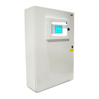
Honeywell touchpoint Pro Technical Handbook (200 pages)
Brand:
Honeywell
| Category:
Control Systems
| Size: 9.01 MB
Table of Contents
4
Table of Contents
2
Revision History
8
1 Important Safety Information
8
International Standards
9
Warnings
10
Cautions
12
2 Safety Hazards, Warnings and Cautions
12
Safety
15
Location and Description of Warning Labels
18
3 Touchpoint Pro Introduction
18
TPPR Access Levels
18
Table 1. TPPR Access Levels
19
TPPR Control System Layout
21
TPPR System Key Components
26
Table 2. TPPR Module Types
27
Power Supply Options
28
Table 3. PSU Terminal Allocation
29
Table 4. DC-UPS Primary Terminal Allocation
29
Table 5. DC-UPS Secondary Terminal Allocation
30
Table 6. DC-UPS LED Meanings
30
Table 7. Backup Battery Details
32
4 TPPR Mechanical Installation
32
TPPR Siting Considerations
33
Installing Wall Mounted Enclosures
33
Table 8. Approximate Wall Mounted Enclosure Weights
35
Installing Floor Standing Enclosures
36
Installing the TPPR 19". Rack Mounted Unit
37
Installing the TPPR Panel Mount Controller
38
Installing the Battery Enclosure
40
5 TPPR Electrical Installation
40
Power Requirements
41
Cabling Requirements
47
Table 9. AIM Ma Connection Table
49
Table 10. AIM MV Connection Table
50
Table 11. IM Connection Table
51
Table 12. ROM Connection Table (Unpowered)
52
Controller Electrical Connections
52
Table 13. RCM Connection Table
54
Table 14. Communications Ring Cable
55
Table 15. System State Relay Connections
55
Table 16. PSU Input Connections
56
First Time Switch On
57
6 Modbus Installation (Option)
57
Introduction
57
Programming the Host
57
Addressing Conventions and Register Values
58
Modbus Bus Interface Board (BIB) Installation
60
Modbus Cables
60
Modbus Electrical Connections
60
Modbus RTU Connections
60
Modbus Termination Resistor
61
Modbus Configuration Examples
62
Modbus Jumper Settings and Termination Resistor Fitting
62
Modbus Multi-Drop Mode
63
7 Software Setup and Commissioning
63
How to Setup or Change the Touchscreen Panel Configuration
63
How to Calibrate the Touchscreen
64
How to Edit Service Contact Settings
64
Configuring the Touchpoint Pro TCP/IP Address and Printer
65
Enabling Tppr's Remote Connection Port
65
How to Print Active Events
66
8 Calibrating Gas Sensors
67
Calibrating Aim-MV Input Channels
69
Calibrating Aim-Ma Input Channel Loops
72
9 Configuring System Parameters
72
General Considerations
73
Analogue Input Module 4-20 Ma Parameters
82
Analogue Input Module MV Bridge Parameters
89
Digital Input Module Parameters
91
Relay Output Module Parameters
92
Cause & Effect Matrix
98
Control of Output Channels - Priority
98
Power Supply Unit Parameters
99
10 Configuring STEL and LTEL Alarms
99
STEL Operation
100
LTEL Operation
103
11 Configuring Modbus
103
Modbus Register Allocation for Function 02 - Read Input Status
103
Table 17. Modbus Parameter Settings
103
Table 18. Modbus Input Channels
103
Table 19. Modbus Output Channels
104
Modbus Register Allocation for Function 04 - Read Input Registers
104
Table 20. Modbus System Summary
104
Table 21. Modbus System Summary Continued
104
Table 22. Modbus System Summary Continued
104
Table 23. Modbus Channel Analogue Values
104
Table 24. Modbus Channel Analogue Values (Float)
105
Register Allocation for Function 03 / 06 / 16 - Read / Write Holding Registers
105
Table 25. Modbus Channel Animation Register
105
Table 26. Modbus Channel Animation Register Continued
106
Table 27. Query Poll Register
106
Table 28. Query Poll Register Values
106
Table 29. Query Poll Descriptions
106
Table 30. Query Poll Types
107
Command Types
107
Table 31. Query Poll Example
107
Table 32. Command Poll Registers
107
Table 33. Command Poll Register Values
107
Table 34. Command Types
108
Exception Responses
108
Table 35. Command Type Example
108
Table 36. Modbus Exception Responses
109
12 Configuration Files
109
Viewing and Editing the Configuration
110
To Back Up the Configuration
110
Restoring the Configuration
111
Deleting the Configuration
112
CCB Configuration Settings
114
13 Normal Day-To-Day Operation
114
TPPR Controller Touchscreen Interface
114
TPPR PC Configuration Software Interface
114
TPPR Webserver Interface
115
TPPR Safety Function
115
Touchscreen Operation
115
Table 37. System Alert Icons
119
How to Recalibrate the Touchscreen
119
Touchscreen Calibration
119
How to View Input Channels and Input Details
119
Table 38. Input Channel Menu Options
120
How to View Output Channels
121
How to View the Trend Graph
121
Table 39. Inhibit / Force Options
122
How to View Event History
122
How to View Event Reports
122
How to Access Diagnostic Information
123
Managing the Integral SD Card
124
Accessing Help
124
System State Relays
124
Table 40. System State Relay Operation
125
14 Alarms, Faults, Warnings and Inhibits
125
Latching Alarms
125
STEL / LTEL Alarms
126
Rate Alarm
126
Relay Activated Outputs
127
Sensor Over Range Operation
127
Catalytic Sensor Over Range Operation
127
Full Scale Exceeded and Over Range Warning Operation
129
Special Considerations When Using Catalytic Sensors
131
Responding to Alarms, Faults and Warnings
133
Viewing Faults and Warnings
134
Inhibiting a Channel
136
15 Maintenance Procedures
136
Routine Maintenance
137
Periodic Maintenance
138
16 How to Test the TPPR System
138
Introduction
139
LED Panel Test
139
Field Inputs Test
140
Configuration Settings Test
141
Cause and Effect Test
142
Panel Button Test
142
System Relay Test
143
LCD Screen Test
143
How to Exercise the Output Relays
144
How to Remove or Replace Modules
147
How to Add or Install a New I/O Module
148
How to Check the DC-UPS
149
How to Change the Battery Protection Fuse
149
How to Replace Batteries
150
17 System Troubleshooting
150
Observed Problem
153
Other Issues
154
18 Error Codes
165
19 Ring Communication Errors
165
Module Faults
165
Troubleshooting Module Faults First Response
166
Troubleshooting Module Faults Second Response
167
Ring Fault Diagnostics and Debugging Techniques
170
20 Further Assistance and Training
171
21 TPPR Specifications
171
Rack Mounted Equipment
173
Wall Mounted Enclosures
175
Floor Standing Enclosures
176
Power Supplies and Fuses
180
Control Module and User Interface
181
I/O Modules
184
22 Certification
184
EU Declaration of Conformity
184
Applicable National and International Standards
185
National and International Certificates for Zone 2 DIV. 2
185
European Performance Approval (DEKRA Exam) for Systems
189
23 Ordering Information
189
TPPR System ID Configuration
190
TPPR Components Part Numbers
191
24 Disposal of Redundant / Unserviceable Parts
191
Restriction of Hazardous Substances (Rohs) Directive
191
Waste Electrical and Electronic Equipment (WEEE) Directive
191
TPPR System Construction
193
25 Table of Icons
195
26 List of Illustrations
198
Tables 27 List of Tables
198
27 List Of Tables
Advertisement
Honeywell touchpoint Pro Operating Instructions Manual (241 pages)
Brand:
Honeywell
| Category:
Controller
| Size: 7.04 MB
Table of Contents
2
Table of Contents
8
Safety and Information
11
How to Use This Manual
12
Safety Hazards
14
Location and Description of Warning Labels
15
Equipment Rating Labels (Hazardous Locations)
16
Disposal
17
Batteries
18
Information
19
Overview / Introduction
20
Touchpoint Pro Controller
21
System Topology
22
Input/Output (I/O) Modules
23
Available Modules
24
Sensor Catalogue
25
Power Supply Options
26
Touchpoint Pro UPS Module with Backup Battery
27
Mechanical Installation
29
Small Wall Mounted Enclosure – Mild Steel
30
Large Wall Mounted Enclosure – Mild Steel
31
Hazardous Area Enclosure
32
Floor Standing Enclosures
33
Floor Standing Cabinet - Front Access
35
Floor Standing Cabinet - Rear Access
37
Rack Mounted Unit
39
Touchpoint Pro Battery Box
41
Touchpoint Pro Battery Box Assembly
43
Cooling and Ventilation
44
Electrical Installation
45
DC Power Input
46
Ring Network
47
VDC Power - Controller
48
Earthing
50
EMC / RFI Considerations
51
Electrical Connections
54
Power Redundancy Module
55
UPS and Battery Box
57
Analogue Input Module 4-20 Ma
60
Analogue Input Module MV Bridge
61
Digital Input Module
62
Relay Output Module
64
Ring Coupling Module
86
Commission Power Supply Unit Status Channels
87
Buzzer Activation and Button Password Protection
88
Calibrate Touch Panel
89
Calibrate MV Input Channels
90
Calibrate Ma Input Channel Loops
92
Normal Operation
94
Navigation - Inputs and Outputs Screens
95
Navigation - Active Events
96
Overview – Web Server Interface
98
Navigation – Inputs and Outputs Screens
99
Navigation – Active Events
100
Alarms
101
Acknowledge an Active Alarm
102
Faults and Warnings
103
Reset a Latched Fault or Warning
104
View Input Channels and Input Details
105
View Output Channels
107
View Trend Graph
108
View Event History
109
Access Diagnostic Information
110
Maintenance
111
Field Inputs Test
112
Configuration Settings Test
113
Cause and Effect Test
114
Routine Maintenance
115
How to Replace a Faulty I/O Module
120
How to Remove or Decommission an I/O Module
122
Backup / Restore Configuration
123
Change the SD Card
126
Touchpoint Pro Battery Box
128
Routine Maintenance
129
Problem Solving
132
List of Error Codes
143
Further Assistance
144
Specifications
145
U Remote Unit Enclosure Without User Interface
147
Floor Standing Enclosures
148
Floor Standing Cabinets Front Access
149
DIN Rail (Module Supply and Communication)
150
Power Supply Redundancy Module (RDN Module)
151
Backup Batteries
152
Control Module and User Interface
153
Analogue Input Module MV Bridge
154
Digital Input Module
155
Certification
156
National and International Certificates
158
Ordering Information
160
Touchpoint Pro Control System Part Number Generator
161
TPPR-V Controllers and Remote Units
163
TPPR-H Enclosures
175
TPPR-W Psus
176
Honeywell Analytics Product Warranty
177
Appendix 1 - Modbus Option
178
Installation
179
Cable Recommendation
180
Electrical Connections
184
Multi-Drop Mode
185
Configuration
186
Register Allocation for Function 02 – Read Input Status
187
Register Allocation for Function 04 – Read Input Registers
188
Query Poll Registers
189
Query Types Available
190
Command Poll Registers
191
Exception Responses
192
Appendix 2 - Configurable Parameter Reference Guide
193
Sensor Settings
194
Suppression Settings
195
Threshold Alarm Hysteresis
196
Rate Alarm Settings 1
197
Inhibit Delay Settings
198
Gas Range Fault Settings
199
Calibration Signal Settings
200
Fault Signalling Settings 1
201
Analogue Input Module MV Bridge
202
Sensor Settings
203
Suppression Settings
204
Threshold Alarm Hysteresis
205
Inhibit Delay Settings
206
Calibration Reminder Settings
207
Digital Input Module
208
Alarm Settings
209
Relay Output Module
210
Cause and Effect Type Selection
211
Appendix 3 - Wiring Diagrams
212
AIM 4-20 Ma with 2 Wire Device Powered By AIM Ma
213
AIM 4-20 Ma with 3 Wire Device Powered By External Power Supply
214
AIM 4-20 Ma with 2 Wire Device Powered By External Power Supply
215
DIM in Unsupervised Configuration
216
DIM in Supervised Open Circuit Configuration
217
DIM in Supervised Configuration
218
AIM MV with Sensor Connectivity
219
ROM with Internal Auxiliary Supply in NC and NO Configuration
220
ROM with External Auxiliary Supply in NC and NO Configuration
221
Appendix 4 - Abbreviations
222
Appendix 5 - User Interface Software Menu Structure
227
Appendix 6 - Glossary of Icons
230
Appendix 7 - Logged Events and Where They Are Displayed
Honeywell touchpoint Pro Operating Manual (100 pages)
Brand:
Honeywell
| Category:
Control Systems
| Size: 4.73 MB
Table of Contents
5
Table of Contents
10
1 Important Safety Information
10
International Standards
11
Warnings
12
Cautions
12
Intended Readers
12
Conventions Used
13
TPPR Documentation Suite
13
Document Translations
13
Associated Documents
13
How to Use This Document
13
Further Information and Help
14
2 Safety Hazards, Warnings and Cautions
14
Safety
14
Warnings and Cautions
15
Safety Hazards
17
Location and Description of Warning Labels
17
Safety Warning Labels
18
Equipment Rating Labels (Hazardous Locations)
19
Warning Labels
20
3 Touchpoint Pro Introduction
20
TPPR Access Levels
21
TPPR Control System Layout
22
Centralised Command and Control Option
22
Distributed Command and Control (Remote Units) Option
23
TPPR System Key Components
23
Enclosures and Racks
23
TPPR Controller User Interfaces
24
SD Card
24
USB Port
24
PC Configuration Software
24
Webserver Software
24
PC Operating Systems
24
Supported Web Browsers
25
Licences
25
TPPR Controller Hardware
26
TPPR Backplane
26
Ring Network
28
TPPR Modules
28
Sensor Catalogue
29
Power Supply Options
29
Power Supply Unit Modules (PSU)
30
Power Redundancy Module (RDN)
31
DC Uninterruptible Power Supply (DC-UPS) Module
32
Backup Batteries
34
4 Configuration Files
34
Viewing and Editing the Configuration
34
To View or Edit the Configuration
35
To Back Up the Configuration
35
Restoring the Configuration
35
Deleting the Configuration
36
5 Normal Day-To-Day Operation
36
TPPR Controller Touchscreen Interface
36
TPPR PC Configuration Software Interface
36
TPPR Webserver Interface
37
TPPR Safety Function
37
Touchscreen Operation
37
System Status Screen Alert Icons
38
Active Event History
38
Touchscreen Layout
39
Touchscreen Navigation
41
Login Requirements
41
How to Recalibrate the Touchscreen
41
How to View Input Channels and Input Details
42
How to View Output Channels
43
How to View the Trend Graph
43
To View the Trend Graph
44
How to View Event History
44
How to View Event Reports
44
How to Generate Reports
44
How to Print Active Events
45
How to Access Diagnostic Information
45
Managing the Integral SD Card
45
SD Card Purposes
46
SD Card Management
46
SD Capacity Reporting
46
How to Check the SD Card Capacity
46
Ejecting the SD Card
46
Replacing an SD Card
46
Accessing Help
47
System State Relays
47
ROM Output Relays On System Fail
48
6 Alarms, Faults, Warnings and Inhibits
48
Latching Alarms
48
STEL / LTEL Alarms
48
Using the STEL Alarm
49
Assigning the STEL Alarm to an Output Relay
49
Rate Alarm
49
Relay Activated Outputs
49
Sensor Over Range Operation
50
Gas Readings
50
Sensor Over Range Operation
50
Catalytic Sensor Over Range Operation
50
Full Scale Exceeded and Over Range Warning Operation
51
Event Status with a Rising Gas Reading
51
Event Status As the Gas Concentration Decreases
52
Special Considerations When Using Catalytic Sensors
52
Configuration of Relay Outputs
53
Responding to Alarms, Faults and Warnings
54
To View Active Alarms
54
To Acknowledge an Active Alarm
55
To Reset a Latched Alarm
55
Viewing Faults and Warnings
55
To View Faults and Warnings
56
To Acknowledge (Accept) a Fault or Warning
56
To Reset a Latched Fault or Warning
56
Inhibiting a Channel
56
How to Inhibit a Channel
57
Channel Auto-Inhibits
58
7 Maintenance Procedures
58
Routine Maintenance
59
Periodic Maintenance
59
Battery Enclosure Maintenance
59
Cable Maintenance
60
8 How to Test the TPPR System
60
Introduction
61
LED Panel Test
61
Field Inputs Test
62
Configuration Settings Test
62
How to Use the Configuration Settings Test Mode
63
Cause and Effect Test
63
How to Use the Cause and Effect Test Mode
64
Panel Button Test
64
System Relay Test
65
LCD Screen Test
65
How to Exercise the Output Relays
66
9 Calibrating Gas Sensors
66
Calibration Definitions
67
Calibrating Aim-MV Input Channels
67
Calibrating Aim-Ma Input Channel Loops
68
10 System Troubleshooting
68
Observed Problem
71
Other Issues
71
Modules Reporting a Fault
72
11 Error Codes
83
12 Other Potential Issues
83
Batteries Fail to Come Online
83
DC-UPS Shows That Batteries Are Failing
83
Module Faults
83
Modules Reporting a Fault
84
Spurious Fault Reporting
85
13 Further Assistance and Training
86
14 EU Declaration of Conformity
86
Applicable National and International Standards
87
National and International Certificates for Zone 2 DIV. 2
87
European Performance Approval (DEKRA Exam) for Systems
88
Approved Components
89
Special Conditions for Use When Used for Explosion Protection
89
Special Conditions for Use When Used for Measurement of Toxic Gases or Oxygen
90
Configuration of Relay Outputs for Safety-Related Switching Operations
90
Compliance with EN 45544-2 (Toxic Gases)
90
Compliance with EN 50104 (Oxygen)
90
Important Notes On Certification
91
15 Ordering Information
91
TPPR System ID Configuration
92
TPPR Components Part Numbers
93
16 Disposal of Redundant / Unserviceable Parts
93
Restriction of Hazardous Substances (Rohs) Directive
93
Waste Electrical and Electronic Equipment (WEEE) Directive
93
TPPR System Construction
93
TPPR Safe Area Enclosures
93
TPPR Battery Enclosure
94
TPPR Power Supply Units
94
TPPR Ring Coupling Module
94
TPPR Backplanes
94
TPPR Packaging
95
17 Table of Icons
97
18 List of Illustrations
99
19 List of Tables
Advertisement
Honeywell touchpoint Pro Security Manual (12 pages)
Brand:
Honeywell
| Category:
Controller
| Size: 0.42 MB
Table of Contents
4
1 Contents
4
Table of Contents
5
2 Introduction
5
Scope
5
Assumptions and Pre-Requisites
5
Related Documents
5
Security Controls
5
Additional User Controls
6
3 IT System Architecture
6
Ethernet Remote Connections
6
Physical and Local Connections
7
4 Threats
7
Unauthorised Access
7
Communications Snooping
7
Viruses and Other Malicious Software Agents
8
5 Mitigation Strategies
8
Touchpoint Pro System
8
Monitor System Access
8
User Access and Passwords
9
Software and Unusual Operation
9
Memory Media
9
Configuration Port
9
Software and Firmware Updates
9
Computers and Access
9
Operating Software
10
User Access and Passwords
10
Networks, Firewalls & VPN Connections
10
Physical Access
10
Firewall and DMZ
10
Internet and VPN
11
6 Glossary
11
Abbreviations
Share and save
Advertisement
Related Products
Honeywell Touchpoint Plus
Honeywell T775U Series
Honeywell T775A2009
Honeywell T775B2016
Honeywell T775M2014
Honeywell T775M2022
Honeywell T775M2030
Honeywell T775R2001
Honeywell T775B2024
Honeywell TP973
Honeywell Categories
Thermostat
Controller
Security Camera
Control Unit
Accessories
More Honeywell Manuals
×
Login
Sign In
OR
Sign in with Facebook
Sign in with Google
×
Upload manual
Upload from disk
Upload from URL