
Subscribe to Our Youtube Channel
Related Manuals for Planet WGSW-52040


Summary of Contents for Planet WGSW-52040
- Page 1 Configuration Guide 48-Port 10/100/1000Base-T + 4-Port 100/1000X SFP Managed Switch WGSW-52040 www.PLANET.com.tw...
-
Page 2: Fcc Warning
Trademarks Copyright © PLANET Technology Corp. 2013. Contents are subject to revision without prior notice. PLANET is a registered trademark of PLANET Technology Corp. All other trademarks belong to their respective owners. Disclaimer PLANET Technology does not warrant that the hardware will work properly in all environments and applications, and makes no warranty and representation, either implied or expressed, with respect to the quality, performance, merchantability, or fitness for a particular purpose. -
Page 3: Table Of Contents
Contents CHAPTER 1 INTRODUCTION ..................1-1 1.1 P ..........................1-1 ACKET ONTENTS 1.2 P ........................1-1 RODUCT ESCRIPTION 1.3 P ........................... 1-3 RODUCT EATURES 1.4 P ........................1-5 RODUCT PECIFICATIONS CHAPTER 2 INSTALLATION..................2-1 2.1 H ........................2-1 ARDWARE ESCRIPTION 2.1.1 Switch Front Panel ........................ - Page 4 4.4.4 SNMP Configuration ......................4-10 4.4.5 Typical SNMP Configuration Examples ................4-14 4.4.6 SNMP Troubleshooting ......................4-15 4.5 S ..........................4-16 WITCH PGRADE 4.5.1 Switch System Files ......................4-16 4.5.2 BootROM Upgrade........................ 4-16 4.5.3 FTP/TFTP Upgrade....................... 4-19 CHAPTER 5 FILE SYSTEM OPERATIONS..............5-29 5.1 I ..................
- Page 5 10.3 ULDP F .................... 10-23 UNCTION YPICAL XAMPLES 10.4 ULDP T ......................10-24 ROUBLESHOOTING CHAPTER 11 LLDP FUNCTION OPERATION CONFIGURATION ......11-26 11.1 I LLDP F ....................11-26 NTRODUCTION TO UNCTION 11.2 LLDP F ............... 11-27 UNCTION ONFIGURATION EQUENCE 11.3 LLDP F ....................
- Page 6 16.4 DDM T ......................16-60 ROUBLESHOOTING CHAPTER 17 LLDP-MED ....................17-61 17.1 I LLDP-MED ...................... 17-61 NTRODUCTION TO 17.2 LLDP-MED C ................17-61 ONFIGURATION EQUENCE 17.3 LLDP-MED E ........................17-64 XAMPLE 17.4 LLDP-MED T ....................17-67 ROUBLESHOOTING CHAPTER 18 BPDU-TUNNEL CONFIGURATION............18-67 18.1 I ....................
- Page 7 20.5 M VLAN T ..............20-90 ULTI RANSLATION ONFIGURATION 20.5.1 Introduction to Multi-to-One VLAN Translation ..............20-90 20.5.2 Multi-to-One VLAN Translation Configuration..............20-90 20.5.3 Typical application of Multi-to-One VLAN Translation............20-91 20.5.4 Multi-to-One VLAN Translation Troubleshooting .............. 20-93 20.6 D VLAN C ....................
- Page 8 22.3 MSTP C ....................22-119 ONFIGURATION 22.4 MSTP E .......................... 22-124 XAMPLE 22.5 MSTP T ......................22-129 ROUBLESHOOTING CHAPTER 23 QOS CONFIGURATION..............23-130 23.1 I S ....................... 23-130 NTRODUCTION TO 23.1.1 QoS Terms ........................23-130 23.1.2 QoS Implementation ....................... 23-131 23.1.3 Basic QoS Model ......................23-132 23.2 Q ....................
- Page 9 26.4 ARP ............................. 26-16 26.4.1 Introduction to ARP ......................26-16 26.4.2 ARP Configuration Task List....................26-16 26.4.3 ARP Troubleshooting ......................26-17 CHAPTER 27 ARP SCANNING PREVENTION FUNCTION CONFIGURATION..27-18 27.1 I ARP S ............27-18 NTRODUCTION TO CANNING REVENTION UNCTION 27.2 ARP S ............
- Page 10 32.4 DHCP ..............32-46 REFIX ELEGATION ERVER ONFIGURATION 32.5 DHCP ..............32-48 REFIX ELEGATION LIENT ONFIGURATION 32.6 DHCP .................... 32-48 ONFIGURATION XAMPLES 32.7 DHCP ......................32-50 ROUBLESHOOTING CHAPTER 33 DHCP OPTION 82 CONFIGURATION..........33-52 33.1 I DHCP O 82 ..................... 33-52 NTRODUCTION TO PTION 33.1.1 DHCP Option 82 Message Structure ................
- Page 11 37.3 DHCP S 82 A ..............37-86 NOOPING PTION PPLICATION XAMPLES 37.4 DHCP S 82 T ................37-87 NOOPING PTION ROUBLESHOOTING CHAPTER 38 IPV4 MULTICAST PROTOCOL ............38-88 38.1 IP ..................38-88 ULTICAST ROTOCOL VERVIEW 38.1.1 Introduction to Multicast ....................38-88 38.1.2 Multicast Address ......................
- Page 12 42.1.1 The Authentication Structure of 802.1x ................42-135 42.1.2 The Work Mechanism of 802.1x ..................42-137 42.1.3 The Encapsulation of EAPOL Messages ................ 42-138 42.1.4 The Encapsulation of EAP Attributes ................42-140 42.1.5 The Authentication Methods of 802.1x................42-141 42.1.6 The Extension and Optimization of 802.1x ..............42-146 42.1.7 The Features of VLAN Allocation ..................
- Page 13 46.3 TACACS+ S ................. 46-172 CENARIOS YPICAL XAMPLES 46.4 TACACS+ T ....................46-173 ROUBLESHOOTING CHAPTER 47 RADIUS CONFIGURATION..............47-174 47.1 I RADIUS ......................47-174 NTRODUCTION TO 47.1.1 AAA and RADIUS Introduction..................47-174 47.1.2 Message structure for RADIUS..................47-174 47.2 RADIUS C ...................
- Page 14 CHAPTER 52 WEB PORTAL CONFIGURATION............52-204 52.1 I ................ 52-204 NTRODUCTION TO ORTAL UTHENTICATION 52.2 W ............52-204 ORTAL UTHENTICATION ONFIGURATION 52.3 W ............... 52-207 ORTAL UTHENTICATION YPICAL XAMPLE 52.4 W ..............52-208 ORTAL UTHENTICATION ROUBLESHOOTING CHAPTER 53 VLAN-ACL CONFIGURATION ...............53-1 53.1 I VLAN-ACL ......................
- Page 15 57.4 ULSM T ......................57-31 ROUBLESHOOTING CHAPTER 58 MIRROR CONFIGURATION ..............58-32 58.1 I ......................58-32 NTRODUCTION TO IRROR 58.2 M ....................58-32 IRROR ONFIGURATION 58.3 M ........................58-33 IRROR XAMPLES 58.4 D ....................58-34 EVICE IRROR ROUBLESHOOTING CHAPTER 59 SFLOW CONFIGURATION..............59-35 59.1 I ......................
- Page 16 64.3 E ......................64-58 XAMPLES OF UMMER 64.4 S ....................64-59 UMMER ROUBLESHOOTING CHAPTER 65 DNSV4/V6 CONFIGURATION ..............65-60 65.1 I DNS ......................... 65-60 NTRODUCTION TO 65.2 DNS ..................65-61 ONFIGURATION 65.3 T DNS......................65-63 YPICAL XAMPLES OF 65.4 DNS T .......................
-
Page 17: Chapter 1 Introduction
WRR and RADIUS authentication besides the IPv4 protocol supported. Supporting IPv6 management features and also backward compatible with IPv4, the WGSW-52040 helps the enterprises to step in the IPv6 era with the lowest investment. Besides, you don’t need to replace the network facilities when the IPv6 FTTx... - Page 18 The WGSW-52040 provides 802.1Q Tagged VLAN, Q-in-Q, voice VLAN and GVRP protocol. The VLAN groups allowed to be on the WGSW-52040 will be maximally up to 256. By supporting port aggregation, the WGSW-52040 allows the operation of a high-speed trunk combined with multiple ports. It enables up to 32 groups of maximum 8 ports for trunking.
-
Page 19: Product Features
1.3 Product Features Physical Port 48-Port 10/100/1000Base-T Gigabit Ethernet RJ-45 4 100/1000Base-X mini-GBIC/SFP slots, SFP type auto detection RJ-45 to DB9 console interface for Switch basic management and setup IP Stacking Connects with stack member via both Gigabit TP and SFP interfaces ... - Page 20 Port Mirroring to monitor the incoming or outgoing traffic on a particular port (many to many) Provides Port Mirror (many-to-1) Quality of Service 8 priority queues on all switch ports Supports for strict priority and Weighted Round Robin (WRR) CoS policies ...
-
Page 21: Product Specifications
1.4 Product Specifications WGSW-52040 Product 48-Port 10/100/1000Base-T + 4-Port 1000X SFP Managed Gigabit Switch Hardware Specifications Copper Ports 48 10/ 100/1000Base-T RJ-45 auto-MDI/MDI-X ports 4 100/1000Base-X SFP interfaces SFP / Mini-GBIC Slots Console 1 x RS-232 DB9 serial port (9600, 8, N, 1) - Page 22 Supports SNMPv1 / v2c / v3 Supports Security IP safety net management function: avoid unlawful landing at nonrestrictive area Supports Syslog server for IPv4 and IPv6 Supports TACACS+ Layer3 Function Static Route Support maximum 128 static routes Layer2 Function Port disable/enable. Auto-negotiation 10/100/1000Mbps full and half duplex mode selection.
- Page 23 Up to 512 entries Bandwidth Control At least 64Kbps step Supports MAC + port binding IPv4 / IPv6 + MAC + port binding Security IPv4 / IPv6 + port binding Supports MAC filter ARP Scanning Prevention IEEE 802.1x Port-based network access control Authentication AAA Authentication: TACACS+ and IPv4/IPv6 over RADIUS RFC-1213 MIB-II...
- Page 24 IEEE 802.1p Class of service IEEE 802.1Q VLAN Tagging IEEE 802.1x Port Authentication Network Control Environment Temperature: 0 ~ 50 degrees C Operating Relative Humidity: 5 ~ 90% (non-condensing) Temperature: -10 ~ 70 degrees C Storage Relative Humidity: 5 ~ 90% (non-condensing)
-
Page 25: Chapter 2 Installation
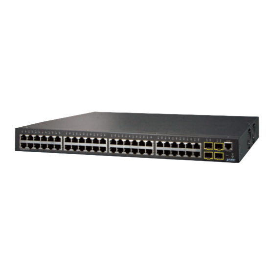
Figure 2-1 shows the front panel of the Managed Switch. WGSW-52040 Front Panel Figure 2-1 WGSW-52040 front panel ■ Gigabit TP interface 10/100/1000Base-T Copper, RJ-45 Twist-Pair: Up to 100 meters. ■ Gigabit SFP slots 100/1000Base-X mini-GBIC slot, SFP (Small Form Factor Pluggable) transceiver module: From 550 meters (Multi-mode fiber), up to 10/20/30/40/50/70/120 kilometers (Single-mode fiber). -
Page 26: Switch Rear Panel
The front panel LEDs indicates instant status of port links, data activity, system operation, Stack status and system power, helps monitor and troubleshoot when needed. WGSW-52040 LED Indication Figure 2-2 WGSW-52040 LED panel ■ System Color Function Green Lights to indicate that the Switch has power. - Page 27 Figure 2-3 Rear panel of WGSW-52040 ■ AC Power Receptacle For compatibility with electric service in most areas of the world, the Managed Switch’s power supply automatically adjusts to line power in the range of 100-240VAC and 50/60 Hz. Plug the female end of the power cord firmly into the receptalbe on the rear panel of the Managed Switch.
-
Page 28: Installing The Managed Switch
2.2 Installing the Managed Switch This section describes how to install your Managed Switch and make connections to the Managed Switch. Please read the following topics and perform the procedures in the order being presented. To install your Managed Switch on a desktop or shelf, simply complete the following steps. In this paragraph, we will describe how to install the Managed Switch and the installation points attended to 2.2.1 Desktop Installation To install the Managed Switch on desktop or shelf, please follows these steps:... -
Page 29: Rack Mounting
Step5: Supply power to the Managed Switch. Connect one end of the power cable to the Managed Switch. Connect the power plug of the power cable to a standard wall outlet. When the Managed Switch receives power, the Power LED should remain solid Green. 2.2.2 Rack Mounting To install the Managed Switch in a 19-inch standard rack, please follow the instructions described below. -
Page 30: Installing The Sfp Transceiver
Figure 2-6 Mounting WGSW-52040 in a Rack Step6: Proceeds with steps 4 and 5 of session 2.2.1 Desktop Installation to connect the network cabling and supply power to the Managed Switch. 2.2.3 Installing the SFP Transceiver The sections describe how to insert an SFP transceiver into an SFP slot. - Page 31 Approved PLANET SFP Transceivers PLANET Managed Switch supports 100/1000 dual mode with both single mode and multi-mode SFP transceivers. The following list of approved PLANET SFP transceivers is correct at the time of publication: Gigabit SFP Transceiver Modules SFP-Port 1000Base-T Module – 100M MGB-GT MGB-SX SFP-Port 1000Base-SX mini-GBIC module –...
- Page 32 MFB-FB20 SFP-Port 100Base-BX Transceiver (WDM,TX:1550nm) - 20KM SFP-Port 100Base-FX Transceiver (1310nm) - 2KM (-40~75 degrees C) MFB-TFX SFP-Port 100Base-FX Transceiver (1310nm) - 20KM (-40~75 degrees MFB-TF20 1. It is recommended to use PLANET SFPs on the Managed Switch. If you insert an SFP transceiver that is not supported, the Managed Switch will not recognize it.
- Page 33 Removing the transceiver module 1. Make sure there is no network activity by checking with the network administrator, or through the management interface of the switch/converter (if available) to disable the port in advance. 2. Remove the Fiber Optic Cable gently. 3....
-
Page 34: Chapter 3 Switch Management
Chapter 3 Switch Management 3.1 Management Options After purchasing the switch, the user needs to configure the switch for network management. Switch provides two management options: in-band management and out-of-band management. 3.1.1 Out-Of-Band Management Out-of-band management is the management through Console interface. Generally, the user will use out-of-band management for the initial switch configuration, or when in-band management is not available. - Page 35 1) Click Start menu - All Programs -Accessories -Communication - HyperTerminal. Figure 3-2 Opening Hyper Terminal 2) Type a name for opening HyperTerminal, such as “Switch”. Figure 3-3 Opening HyperTerminal 3-11...
- Page 36 3) In the “Connect using” drop-list, select the RS-232 serial port used by the PC, e.g. COM1, and click “OK”. Figure 3-4 Opening HyperTerminal 4) COM1 property appears, select “9600” for “Baud rate”, “8” for “Data bits”, “none” for “Parity checksum”, “1” for stop bit and “none”...
-
Page 37: In-Band Management
Step 3: Entering switch CLI interface Power on the switch, the following appears in the HyperTerminal windows, that is the CLI configuration mode for Switch. Testing RAM... 0x077C0000 RAM OK Loading MiniBootROM... Attaching to file system ... Loading nos.img ... done. Booting.. - Page 38 network segment; 3) If 2) is not met, Telnet client can connect to an IPv4/IPv6 address of the switch via other devices, such as a router. The switch is Layer 3 switch that can be configured with several IPv4/IPv6 addresses. The following example assumes the shipment status of the switch where only VLAN1 exists in the system.
- Page 39 Step 2: Run Telnet Client program. Run Telnet client program included in Windows with the specified Telnet target. Figure 3-7 Run telnet client program included in Windows Step 3: Login to the switch. Login to the Telnet configuration interface. Valid login name and password are required, otherwise the switch will reject Telnet access.
-
Page 40: Management Via Http
3.1.2.2 Management via HTTP To manage the switch via HTTP, the following conditions should be met: Switch has an IPv4/IPv6 address configured; The host IPv4/IPv6 address (HTTP client) and the switch’s VLAN interface IPv4/IPv6 address are in the same network segment; If 2) is not met, HTTP client should connect to an IPv4/IPv6 address of the switch via other devices, such as a router. - Page 41 “admin”, and password of “admin”, the configuration procedure should like the following: Switch>enable Switch#config Switch(config)#username admin privilege 15 password 0 admin Switch(config)#authentication line web login local The Web login interface of WGSW-52040 is as below: Figure 3-10 Web Login Interface 3-17...
- Page 42 Input the right username and password, and then the main Web configuration interface is shown as below. Figure 3-11 Main Web Configuration Interface When configure the switch, the name of the switch is composed with English letters. 3.1.2.3 Manage the Switch via SNMP Network Management Software The necessities required by SNMP network management software to manage switches: 1) IP addresses are configured on the switch;...
-
Page 43: Cli Interface
3.2 CLI Interface The switch provides thress management interface for users: CLI (Command Line Interface) interface, Web interface, Snmp netword management software. We will introduce the CLI interface and Web configuration interface in details, Web interface is familiar with CLI interface function and will not be covered, please refer to “Snmp network management software user manual”. -
Page 44: Admin Mode
On entering the CLI interface, entering user entry system first. If as common user, it is defaulted to User Mode. The prompt shown is “Switch>“, the symbol “>“ is the prompt for User Mode. When exit command is run under Admin Mode, it will also return to the User Mode. Under User Mode, no configuration to the switch is allowed, only clock time and version information of the switch can be queries. -
Page 45: Configuration Syntax
VLAN Mode Using the vlan <vlan-id> command under Global Mode can enter the corresponding VLAN Mode. Under VLAN Mode the user can configure all member ports of the corresponding VLAN. Run the exit command to exit the VLAN Mode to Global Mode. ... -
Page 46: Shortcut Key Support
3.2.3 Shortcut Key Support Switch provides several shortcut keys to facilitate user configuration, such as up, down, left, right and Blank Space. If the terminal does not recognize Up and Down keys, ctrl +p and ctrl +n can be used instead. Key(s) Function Back Space... -
Page 47: Input Verification
3.2.5 Input Verification 3.2.5.1 Returned Information: Success All commands entered through keyboards undergo syntax check by the Shell. Nothing will be returned if the user entered a correct command under corresponding modes and the execution is successful. Returned Information: error Output error message Explanation The entered command does not exist, or there is... -
Page 48: Chapter 4 Basic Switch Configuration
Chapter 4 Basic Switch Configuration 4.1 Basic Configuration Basic switch configuration includes commands for entering and exiting the admin mode, commands for entering and exiting interface mode, for configuring and displaying the switch clock, for displaying the version information of the switch system, etc. Command Explanation Normal User Mode/ Admin Mode... -
Page 49: Telnet Management
Global Mode Configure the information displayed when the banner motd <LINE> login authentication of a telnet or console user is no banner motd successful. 4.2 Telnet Management 4.2.1 Telnet 4.2.1.1 Introduction to Telnet Telnet is a simple remote terminal protocol for remote login. Using Telnet, the user can login to a remote host with its IP address of hostname from his own workstation. - Page 50 Enable the Telnet server function in the telnet-server enable switch: the no command disables the no telnet-server enable Telnet function. username <user-name> [privilege Configure user name and password of <privilege>] [password [0 | 7] <password>] the telnet. The no form command deletes no username <username>...
-
Page 51: Ssh
exec Configure command authorization authorization line vty command <1-15> manner and authorization selection {local | radius | tacacs} (none|) priority of login user with VTY (login with no authorization line vty command <1-15> Telnet and SSH). The no command recovers to be default manner. accounting line {console | vty} command <1-15>... - Page 52 connection is established. The information transferred on this connection is protected from being intercepted and decrypted. The switch meets the requirements of SSH2.0. It supports SSH2.0 client software such as SSH Secure Client and putty. Users can run the above software to manage the switch remotely.
-
Page 53: Configure Switch Ip Addresses
4.2.2.3 Example of SSH Server Configuration Example1: Requirement: Enable SSH server on the switch, and run SSH2.0 client software such as Secure shell client or putty on the terminal. Log on the switch by using the username and password from the client. Configure the IP address, add SSH user and enable SSH service on the switch. - Page 54 3. BOOTP configuration 4. DHCP configuration 1. Enable VLAN port mode Command Explanation Global Mode interface vlan <vlan-id> Create VLAN interface (layer 3 interface); the no interface vlan <vlan-id> no command deletes the VLAN interface. 2. Manual configuration Command Explanation VLAN Interface Mode ip address <ip_address>...
-
Page 55: Snmp Configuration
through DHCP negotiation; the no command disables the DHCP client function. 4.4 SNMP Configuration 4.4.1 Introduction to SNMP SNMP (Simple Network Management Protocol) is a standard network management protocol widely used in computer network management. SNMP is an evolving protocol. SNMP v1 [RFC1157] is the first version of SNMP which is adapted by vast numbers of manufacturers for its simplicity and easy implementation;... -
Page 56: Introduction To Mib
or log the event according to the settings. Inform-Request is mainly used for inter-NMS communication in the layered network management. USM ensures the transfer security by well-designed encryption and authentication. USM encrypts the messages according to the user typed password. This mechanism ensures that the messages can’t be viewed on transmission. -
Page 57: Introduction To Rmon
public MIB contains public network management information that can be accessed by all NMS; private MIB contains specific information which can be viewed and controlled by the support of the manufacturers. MIB-I [RFC1156] is the first implemented public MIB of SNMP, and is replaced by MIB-II [RFC1213]. - Page 58 Configure IP address of SNMP management base Configure engine ID Configure user Configure group Configure view Configuring TRAP Enable/Disable RMON 1. Enable or disable SNMP Agent server function Command Explanation Global Mode Enable the SNMP Agent function on the snmp-server enabled switch;...
- Page 59 snmp-server securityip enable Enable or disable secure IP address check function on the NMS. snmp-server securityip disable 4. Configure engine ID Command Explanation Global Mode Configure the local engine ID on the switch. snmp-server engineid <engine-string> no snmp-server engineid This command is used for SNMP v3. 5.
- Page 60 {<ipv6-num-std>|<ipv6-name>}] 7. Configure view Command Explanation Global Mode snmp-server view <view-string> Configure view on the switch. This command <oid-string> {include|exclude} no snmp-server view <view-string> is used for SNMP v3. [<oid-string>] 8. Configuring TRAP Command Explanation Global Mode snmp-server enable traps Enable the switch to send Trap message.
-
Page 61: Typical Snmp Configuration Examples
4.4.5 Typical SNMP Configuration Examples The IP address of the NMS is 1.1.1.5; the IP address of the switch (Agent) is 1.1.1.9. Scenario 1: The NMS network administrative software uses SNMP protocol to obtain data from the switch. The configuration on the switch is listed below: Switch(config)#snmp-server enable Switch(config)#snmp-server community rw private Switch(config)#snmp-server community ro public... -
Page 62: Snmp Troubleshooting
The configuration on the switch is listed below: Switch(config)#snmp-server enable Switch(config)#snmp-server community rw private Switch(config)#snmp-server community ro public Switch(config)#snmp-server securityip 2004:1:2:3::2 The NMS can use private as the community string to access the switch with read-write permission, or use public as the community string to access the switch with read-only permission. -
Page 63: Switch Upgrade
4.5 Switch Upgrade Switch provides two ways for switch upgrade: BootROM upgrade and the TFTP/FTP upgrade under Shell. 4.5.1 Switch System Files The system files includes system image file and boot file. The updating of the switch is to update the two files by overwrite the old files with the new ones. The system image files refers to the compressed files of the switch hardware drivers, and software support program, etc, namely what we usually call the IMG update file. - Page 64 Figure 4-2 Typical topology for switch upgrade in BootROM mode The upgrade procedures are listed below: Step 1: As shown in the figure, a PC is used as the console for the switch. A console cable is used to connect PC to the management port on the switch. The PC should have FTP/TFTP server software installed and has the image file required for the upgrade.
- Page 65 Step 5: Execute write nos.img in BootROM mode. The following saves the system update image file. [Boot]: write nos.img File nos.img exists, overwrite? (Y/N)?[N] y Writing nos.img............. Write nos.img OK. [Boot]: Step 6: The following update file boot.rom, the basic environment is the same as Step 4. [Boot]: load boot.rom Loading…...
-
Page 66: Ftp/Tftp Upgrade
startup-config 2,922 1980-01-01 00:09:14 ---- temp.img 2,431,631 1980-01-01 00:00:32 ---- 2. CONFIG RUN command Used to set the IMAGE file to run upon system start-up, and the configuration file to run upon configuration recovery. [Boot]: config run Boot File: [nos.img] nos.img Config File: [boot.conf] 4.5.3 FTP/TFTP Upgrade 4.5.3.1 Introduction to FTP/TFTP... - Page 67 to provide data connection service. TFTP builds upon UDP, providing unreliable data stream transfer service with no user authentication or permission-based file access authorization. It ensures correct data transmission by sending and acknowledging mechanism and retransmission of time-out packets. The advantage of TFTP over FTP is that it is a simple and low overhead file transfer service.
- Page 68 Start up configuration file: refers to the configuration sequence used in switch startup. Startup configuration file stores in nonvolatile storage, corresponding to the so-called configuration save. If the device does not support CF, the configuration file stores in FLASH only, if the device supports CF, the configuration file stores in FLASH or CF, if the device supports multi-config file, names the configuration file to be .cfg file, the default is startup.cfg.
- Page 69 (2) Configure TFTP server connection idle time (3) Configure retransmission times before timeout packets without acknowledgement (4) Shut down TFTP server 1. FTP/TFTP client configuration (1)FTP/TFTP client upload/download file Command Explanation Admin Mode copy <source-url> <destination-url> FTP/TFTP client upload/download file. [ascii | binary] (2)For FTP client, server file list can be checked.
- Page 70 Command Explanation Global Mode ftp-server timeout <seconds> Set connection idle time. 3. TFTP server configuration (1)Start TFTP server Command Explanation Global Mode Start TFTP server, the no command shuts down tftp-server enable TFTP server and prevents TFTP user from no tftp-server enable logging in.
- Page 71 10.1.1.2 10.1.1.1 Figure 4-2 Download nos.img file as FTP/TFTP client Scenario 1: The switch is used as FTP/TFTP client. The switch connects from one of its ports to a computer, which is a FTP/TFTP server with an IP address of 10.1.1.1; the switch acts as a FTP/TFTP client, the IP address of the switch management VLAN is 10.1.1.2.
- Page 72 Switch(config)#interface vlan 1 Switch(Config-if-Vlan1)#ip address 10.1.1.2 255.255.255.0 Switch(Config-if-Vlan1)#no shut Switch(Config-if-Vlan1)#exit Switch(config)#exit Switch#copy tftp: //10.1.1.1/12_30_nos.img nos.img Scenario 2: The switch is used as FTP server. The switch operates as the FTP server and connects from one of its ports to a computer, which is a FTP client. Transfer the “nos.img” file in the switch to the computer and save as 12_25_nos.img.
- Page 73 “nos.img” file from the switch to the computer. Scenario 4: Switch acts as FTP client to view file list on the FTP server. Synchronization conditions: The switch connects to a computer by an Ethernet port, the computer is a FTP server with an IP address of 10.1.1.1;...
- Page 74 When upload/download system file with FTP protocol, the connectivity of the link must be ensured, i.e., use the “Ping” command to verify the connectivity between the FTP client and server before running the FTP program. If ping fails, you will need to check for appropriate troubleshooting information to recover the link connectivity.
- Page 75 ensured, i.e., use the “Ping” command to verify the connectivity between the TFTP client and server before running the TFTP program. If ping fails, you will need to check for appropriate troubleshooting information to recover the link connectivity. The following is the message displays when files are successfully transferred. Otherwise, please verify link connectivity and retry “copy”...
-
Page 76: Chapter 5 File System Operations
Chapter 5 File System Operations 5.1 Introduction to File Storage Devices File storage devices used in switches mainly include FLASH cards. As the most common storage device, FLASH is usually used to store system image files (IMG files), system boot files (ROM files) and system configuration files (CFG files). - Page 77 Command Explanation Admin Configuration Mode rmdir <directory> Delete a sub-directory in a designated directory on a certain device. 4. Changing the current working directory of the storage device Command Explanation Admin Configuration Mode cd <directory> Change the current working directory of the storage device.
-
Page 78: Typical Applications
9. The copy operation of files Command Explanation Admin Configuration Mode copy <source-file-url > <dest-file-url> Copy a designated file one the switch and store it as a new one. 5.3 Typical Applications Copy an IMG file flash:/nos.img stored in the FLASH on the boardcard, to cf:/nos-6.1.11.0.img. The configuration of the switch is as follows: Switch#copy flash:/nos.img flash:/nos-6.1.11.0.img Copy flash:/nos.img to flash:/nos-6.1.11.0.img? [Y:N] y... -
Page 79: Chapter 6 Cluster Configuration
Chapter 6 Cluster Configuration 6.1 Introduction to cluster network management Cluster network management is an in-band configuration management. Unlike CLI, SNMP and Web Config which implement a direct management of the target switches through a management workstation, cluster network management implements a direct management of the target switches (member switches) through an intermediate switch (commander switch). - Page 80 2. Create cluster 1) Configure private IP address pool for member switches of the cluster 2) Create or delete cluster 3) Add or remove a member switch 3. Configure attributes of the cluster in the commander switch 1) Enable or disable automatically adding cluster members 2) Set automatically added members to manually added ones 3) Set or modify the time interval of keep-alive messages on switches in the cluster.
- Page 81 2. Create a cluster Command Explanation Global Mode cluster ip-pool <commander-ip> Configure the private IP address pool no cluster ip-pool for cluster member devices. cluster commander [<cluster_name>] Create or delete a cluster. no cluster commander cluster member {nodes-sn <nodes-sn> | mac-address <mac-addr>...
- Page 82 4. Configure attributes of the cluster in the candidate switch Command Explanation Global Mode cluster keepalive interval <second> Set the keep-alive interval of the no cluster keepalive interval cluster. Set the max number of lost cluster keepalive loss-count <int> keep-alive messages that can be no cluster keepalive loss-count tolerated in the clusters.
- Page 83 Enable http function in commander switch and member switch. Notice: must insure the http function be enabled in member switch when ip http server commander switch visiting member switch by web. The commander switch visit member switch via beat member node in member cluster topology.
-
Page 84: Examples Of Cluster Administration
6.3 Examples of Cluster Administration Scenario: The four switches SW1-SW4, amongst the SW1 is the command switch and other switches are member switch. The SW2 and SW4 is directly connected with the command switch, SW3 connects to the command switch through SW2. Figure 6-1: Examples of Cluster Configuration Procedure 1. - Page 85 protocol from broadcasting the private cluster addresses in this VLAN to other switches and cause routing loops. Whether the connection between the command switch and the member switch is correct. We can use the debug cluster packets to check if the command and the member switches can receive and process related cluster admin packets correctly.
-
Page 86: Chapter 7 Port Configuration
Chapter 7 Port Configuration 7.1 Introduction to Port Switch contains Cable ports and Combo ports. The Combo ports can be configured to as either 1000GX-TX ports or SFP Gigabit fiber ports. If the user needs to configure some network ports, he/she can use the interface ethernet <interface-list>... - Page 87 1. Enter the Ethernet port configuration mode Command Explanation Global Mode interface ethernet <interface-list> Enters the network port configuration mode. 2. Configure the properties for the Ethernet ports Command Explanation Port Mode media-type {copper | Sets the combo port mode (combo ports copper-preferred-auto | fiber | only).
- Page 88 loopback Enables/Disables loopback test function for specified ports. no loopback Enables the storm control function for broadcasts, multicasts and unicasts with storm control {unicast | broadcast | unknown destinations (short for broadcast), multicast} {kbps <Kbits> | pps <PPS>} and sets the allowed broadcast packet no strom control {unicast | broadcast | number or the bit number passing per multicast}>...
-
Page 89: Port Configuration Example
3. Virtual cable test Command Explanation Admin Mode virtual-cable-test interface ethernet Test virtual cables of the port. <interface-list> 7.3 Port Configuration Example Switch 1 1/10 1/12 Switch 2 Switch 3 Figure 7-1: Port Configuration Example No VLAN has been configured in the switches, default VLAN1 is used. Switch Port Property... -
Page 90: Port Troubleshooting
Switch2: Switch2(config)#interface ethernet 1/9 Switch2(Config-If-Ethernet1/9)#speed-duplex force100-full Switch2(Config-If-Ethernet1/9)#exit Switch2(config)#interface ethernet 1/10 Switch2(Config-If-Ethernet1/10)#speed-duplex force1g-full Switch2(Config-If-Ethernet1/10)#exit Switch2(config)#monitor session 1 source interface ethernet 1/8;1/9 Switch2(config)#monitor session 1 destination interface ethernet 1/10 Switch3: Switch3(config)#interface ethernet 1/12 Switch3(Config-If-Ethernet1/12)#speed-duplex force100-full Switch3(Config-If-Ethernet1/12)#exit 7.4 Port Troubleshooting Here are some situations that frequently occurs in port configuration and the advised solutions: ... -
Page 91: Chapter 8 Port Isolation Function Configuration
Chapter 8 Port Isolation Function Configuration 8.1 Introduction to Port Isolation Function Port isolation is an independent port-based function working in an inter-port way, which isolates flows of different ports from each other. With the help of port isolation, users can isolate ports within a VLAN to save VLAN resources and enhance network security. -
Page 92: Port Isolation Function Typical Examples
3. Display the configuration of port isolation Command Explanation Admin Mode and Global Mode Display the configuration of port isolation, show isolate-port group [ <WORD> ] including all configured port isolation groups and Ethernet ports in each group. 8.3 Port Isolation Function Typical Examples e1/15 Vlan e1/1... -
Page 93: Chapter 9 Port Loopback Detection Function Configuration
Chapter 9 Port Loopback Detection Function Configuration 9.1 Introduction to Port Loopback Detection Function With the development of switches, more and more users begin to access the network through Ethernet switches. In enterprise network, users access the network through layer-2 switches, which means urgent demands for both internet and the internal layer 2 Interworking. -
Page 94: Port Loopback Detection Function Configuration Task List
9.2 Port Loopback Detection Function Configuration Task List 1. Configure the time interval of loopback detection 2. Enable the function of port loopback detection 3. Configure the control method of port loopback detection 4. Display and debug the relevant information of port loopback detection 5.... -
Page 95: Port Loopback Detection Function Example
Command Explanation Admin Mode Enable the debug information of the debug loopback-detection function module of port loopback detection. no debug loopback-detection The no operation of this command will disable the debug information. Display the state and result of the loopback show loopback-detection [interface detection of all ports, if no parameter is provided;... -
Page 96: Port Loopback Detection Troubleshooting
As shown in the above configuration, the switch will detect the existence of loopbacks in the network topology. After enabling the function of loopback detection on the port connecting the switch with the outside network, the switch will notify the connected network about the existence of a loopback, and control the port on the switch to guarantee the normal operation of the whole network. -
Page 97: Introduction To Uldp Function
Chapter 10 ULDP Function Configuration 10.1 Introduction to ULDP Function Unidirectional link is a common error state of link in networks, especially in fiber links. Unidirectional link means that only one port of the link can receive messages from the other port, while the latter one can not receive messages from the former one. -
Page 98: Uldp Configuration Task Sequence
This kind of problem often appears in the following situations: GBIC (Giga Bitrate Interface Converter) or interfaces have problems, software problems, hardware becomes unavailable or operates abnormally. Unidirectional link will cause a series of problems, such as spinning tree topological loop, broadcast black hole. ULDP (Unidirectional Link Detection Protocol) can help avoid disasters that could happen in the situations mentioned above. - Page 99 1. Enable ULDP function globally Command Explanation Global configuration mode uldp enable Globally enable or disable ULDP function. uldp disable 2. Enable ULDP function on a port Command Explanation Port configuration mode uldp enable Enable or disable ULDP function on a port. uldp disable 3.
- Page 100 Global configuration mode Configure the interval of Hello messages, uldp hello-interval <integer> ranging from 5 to 100 seconds. The value no uldp hello-interval is 10 seconds by default. 7. Configure the interval of Recovery Command Explanation Global configuration mode Configure the interval of Recovery reset, uldp recovery-time <integer>...
-
Page 101: Uldp Function Typical Examples
debug uldp event Enable or disable the debug switch of event information. no debug uldp event debug uldp packet {receive|send} Enable or disable the type of messages no debug uldp packet {receive|send} can be received and sent on all ports. debug uldp {hello|probe|echo| unidir|all} [receive|send] interface ethernet Enable or disable the content detail of a... -
Page 102: Uldp Troubleshooting
SwitchA(Config-If-Ethernet1/1)#exit SwitchA(config)#interface ethernet 1/2 SwitchA(Config-If-Ethernet1/2)#uldp enable Switch B configuration sequence: SwitchB(config)#uldp enable SwitchB(config)#interface ethernet1/3 SwitchB(Config-If-Ethernet1/3)#uldp enable SwitchB(Config-If-Ethernet1/3)#exit SwitchB(config)#interface ethernet 1/4 SwitchB(Config-If-Ethernet1/4)#uldp enable As a result, port g1/1, g1/2 of SWITCH A are all shut down by ULDP, and there is notification information on the CRT terminal of PC1. - Page 103 decides the working mode and rate of the ports, ULDP won’t take effect no matter enabled or not. In such situation, the port is considered as “Down”. In order to make sure that neighbors can be correctly created and unidirectional links can be correctly discovered, it is required that both end of the link should enable ULDP, using the same authentication method and password.
-
Page 104: Chapter 11 Lldp Function Operation Configuration
Chapter 11 LLDP Function Operation Configuration 11.1 Introduction to LLDP Function Link Layer Discovery Protocol (LLDP) is a new protocol defined in 802.1ab. It enables neighbor devices to send notices of their own state to other devices, and enables all ports of every device to store information about them. -
Page 105: Lldp Function Configuration Task Sequence
Many kinds of network management software use “Automated Discovery” function to trace the change and condition of topology, but most of them can reach layer-three and classify the devices into all IP subnets at best. This kind of data are very primitive, only referring to basic events like the adding and removing of relative devices instead of details about where and how these devices operate with the network. - Page 106 2. Configure the port-base LLDP function switch Command Explanation Port Mode lldp enable Configure the port-base LLDP function lldp disable switch. 3. Configure the operating state of port LLDP Command Explanation Port Mode Configure the operating state of port lldp mode (send|receive|both|disable) LLDP.
- Page 107 7. Configure the intervals of sending Trap messages Command Explanation Global Mode Configure the intervals of sending lldp notification interval <seconds> Trap messages as the specified value or no lldp notification interval default value. 8. Configure to enable the Trap function of the port Command Explanation Port Configuration Mode...
-
Page 108: Lldp Function Typical Example
12. Display and debug the relative information of LLDP Command Explanation Admin, Global Mode Display the current LLDP configuration show lldp information. Display the LLDP configuration show lldp interface ethernet <IFNAME> information of the current port. Display the information of all kinds of show lldp traffic counters. -
Page 109: Lldp Function Troubleshooting
Figure 11-1: LLDP Function Typical Configuration Example In the network topology graph above, the port 1,3 of SWITCH B are connected to port 2,4 of SWITCH A. Port 1 of SWITCH B is configured to message-receiving-only mode, Option TLV of port 4 of SWITCH A is configured as portDes and SysCap. -
Page 110: Chapter 12 Port Channel Configuration
Chapter 12 Port Channel Configuration 12.1 Introduction to Port Channel To understand Port Channel, Port Group should be introduced first. Port Group is a group of physical ports in the configuration level; only physical ports in the Port Group can take part in link aggregation and become a member port of a Port Channel. -
Page 111: Brief Introduction To Lacp
can only be performed on ports in full-duplex mode. For Port Channel to work properly, member ports of the Port Channel must have the same properties as follows: All ports are in full-duplex mode. All Ports are of the same speed. All ports are Access ports and belong to the same VLAN or are all TRUNK ports, or are ... -
Page 112: Static Lacp Aggregation
configuration (speed, duplex, basic configuration, management Key) of the ports to be aggregated. After the dynamic aggregation port enables LACP protocol, the management Key is 0 by default. After the static aggregation port enables LACP, the management Key of the port is the same with the ID of the aggregation group. -
Page 113: Port Channel Configuration Task List
compare the priority of the systems, if they are same, then compare the MAC address of the systems. The end with a small device ID has the high priority. Compare the ID of the ports (the priority of the port + the ID of the port). For each port in the side of the device which has the high device priority, first, compare the priority of the ports, if the priorities are same, then compare the ID of the ports. - Page 114 3. Enter port-channel configuration mode. Command Explanation Global Mode interface port-channel Enter port-channel configuration mode. <port-channel-number> 4. Set load-balance method for port-group Command Explanation Aggregation port configuration mode load-balance {src-mac | dst-mac | dst-src-mac | Set load-balance for port-group. src-ip | dst-ip | dst-src-ip} 5.
-
Page 115: Port Channel Examples
12.3 Port Channel Examples Scenario 1: Configuring Port Channel in LACP. Figure 12-2: Configure Port Channel in LACP The switches in the description below are all switch and as shown in the figure, ports 1, 2, 3, 4 of S1 are access ports and add them to group1 with active mode. Ports 6, 8, 9, 10 of S2 are access ports and add them to group2 with passive mode. - Page 116 Switch2(Config-If-Port-Channel2)# Configuration result: Shell prompts ports aggregated successfully after a while, now ports 1, 2, 3, 4 of S1 form an aggregated port named “Port-Channel1”, ports 6, 8, 9, 10 of S2 form an aggregated port named “Port-Channel2”; can be configured in their respective aggregated port mode. Scenario 2: Configuring Port Channel in ON mode.
-
Page 117: Port Channel Troubleshooting
Switch2#config Switch2(config)#port-group 2 Switch2(config)#interface ethernet 1/6 Switch2 (Config-If-Ethernet1/6)#port-group 2 mode on Switch2 (Config-If-Ethernet1/6)#exit Switch2 (config)#interface ethernet 1/8-10 Switch2(Config-If-Port-Range)#port-group 2 mode on Switch2(Config-If-Port-Range)#exit Configuration result: Add ports 1, 2, 3, 4 of S1 to port-group1 in order, and we can see a group in “on” mode is completely joined forcedly, switch in other ends won’t exchange LACP PDU to complete aggregation. -
Page 118: Chapter 13 Mtu Configuration
Chapter 13 MTU Configuration 13.1 Introduction to MTU So far the Jumbo (Jumbo Frame) has not reach a determined standard in the industry (including the format and length of the frame). Normally frames sized within 1519-9000 should be considered jumbo frame. Networks with jumbo frames will increase the speed of the whole network by 2% to 5%. -
Page 119: Chapter 14 Efm Oam Configuration
Chapter 14 EFM OAM Configuration 14.1 Introduction to EFM OAM Ethernet is designed for Local Area Network at the beginning, but link length and network scope is extended rapidly while Ethernet is also applied to Metropolitan Area Network and Wide Area Network along with development. Due to lack the effectively management mechanism, it affects Ethernet application to Metropolitan Area Network and Wide Area Network, implementing OAM on Ethernet becomes a necessary development trend. - Page 120 OAM protocol data units (OAMPDU) use destination MAC address 01-80-c2-00-00-02 of protocol, the max transmission rate is 10Pkt/s. EFM OAM is established on the basis of OAM connection, it provides a link operation management mechanism such as link monitoring, remote fault detection and remote loopback testing, the simple introduction for EFM OAM in the following: 1.
- Page 121 Errored frame event: The number of detected error frames over M seconds can not be less than the low threshold. Errored frame seconds event: The number of error frame seconds detected over M seconds can not be less than the low threshold. (Errored frame second: Receiving an errored frame at least in a second.) 3.
-
Page 122: Efm Oam Configuration
Typical EFM OAM application topology is in the following, it is used for point-to-point link and emulational IEEE 802.3 point-to-point link. Device enables EFM OAM through point-to-point connection to monitor the link fault in the First Mile with Ethernet access. For user, the connection between user to telecommunication is “the First Mile”, for service provider, it is “the Last Mile”. - Page 123 Configure transmission period of ethernet-oam period <seconds> OAMPDU (optional), no command no ethernet-oam period restores the default value. Configure timeout of EFM OAM ethernet-oam timeout <seconds> connection, no command restores no ethernet-oam timeout the default value. 2. Configure link monitor Command Explanation Port mode...
- Page 124 3. Configure remote failure Command Explanation Port mode Enable remote failure detection of EFM OAM (failure means ethernet-oam remote-failure critical-event or link-fault event of the no ethernet-oam remote-failure local), no command disables the function. (optional) ethernet-oam errored-symbol-period Configure the high threshold of threshold high {high-symbols | none} errored symbol period event, no no ethernet-oam errored-symbol-period...
-
Page 125: Efm Oam Example
14.3 EFM OAM Example Example: CE and PE devices with point-to-point link enable EFM OAM to monitor “the First Mile” link performance. It will report the log information to network management system when occurring fault event and use remote loopback function to detect the link in necessary instance Figure 14-3: Typical OAM application topology Configuration procedure: (Omitting SNMP and Log configuration in the following) -
Page 126: Efm Oam Troubleshooting
CE(config-if-ethernet1/1)#no ethernet-oam remote-loopback supported 14.4 EFM OAM Troubleshooting When using EFM OAM, it occurs the problem, please check whether the problem is resulted by the following reasons: Check whether OAM entities of two peers of link in passive mode. If so, EFM OAM connection can not be established between two OAM entities. -
Page 127: Chapter 15 Port Security
Chapter 15 PORT SECURITY 15.1 Introduction to PORT SECURITY Port security is a MAC address-based security mechanism for network access controlling. It is an extension to the existing 802.1x authentication and MAC authentication. It controls the access of unauthorized devices to the network by checking the source MAC address of the received frame and the access to unauthorized devices by checking the destination MAC address of the sent frame. -
Page 128: Example Of Port Security
MAC address table or a MAC address is configured to several interfaces in same VLAN, both of them will violate the security of the MAC address. switchport port-security aging {static | time <value> Enable port-security aging | type {absolute | inactivity}} entry of the interface, specify no switchport port-security violation aging {static | aging time or aging type. -
Page 129: Port Security Troubleshooting
Switch(config)#interface Ethernet 1/1 Switch(config-if-ethernet1/1)#switchport port-security Switch(config-if- ethernet1/1)#switchport port-security maximum 10 Switch(config-if- ethernet1/1)#exit Switch(config)# 15.4 PORT SECURITY Troubleshooting If problems occur when configuring PORT SECURITY, please check whether the problem is caused by the following reasons: Check whether PORT SECURITY is enabled normally Check whether the valid maximum number of MAC addresses is configured ... -
Page 130: Chapter 16 Ddm Configuration
Chapter 16 DDM Configuration 16.1 Introduction to DDM 16.1.1 Brief Introduction to DDM DDM (Digital Diagnostic Monitor) makes the detailed digital diagnostic function standard in SFF-8472 MSA. It set that the parameter signal is monitored and make it to digitize on the circuit board of the inner module. -
Page 131: Ddm Function
current, tx power and rx power) can fast locate the fault through Digital Diagnostic function. Besides, the state of Tx Fault and Rx LOS is important for analyzing the fault. 3. Compatibility verification Compatibility verification is used to analyze whether the environment of the module accords the data manual or it is compatible with the corresponding standard, because the module capability is able to be ensured only in the compatible environment. -
Page 132: Ddm Configuration Task List
verification which are decided by the manufacturer. Besides the verification mode of the real-time parameters and the default thresholds are same. 3. Transceiver monitoring Besides checking the real-time working state of the transceiver, the user needs to monitor the detailed status, such as the former abnormity time and the abnormity type. Transceiver monitoring helps the user to find the former abnormity status through checking the log and query the last abnormity status through executing the commands. - Page 133 low-warn} {<value> | default}} 3. Configure the state of the transceiver monitoring (1) Configure the interval of the transceiver monitoring Command Explanation Global mode Set the interval of the transceiver monitor. The no command sets the transceiver-monitoring interval <minutes> no transceiver-monitoring interval interval to be the default interval of 15 minutes.
-
Page 134: Examples Of Ddm
(4)Clear the information of the transceiver monitoring Command Explanation Admin mode clear transceiver threshold-violation [interface Clear the threshold violation of the ethernet <interface-list>] transceiver monitor. 16.3 Examples of DDM Example1: Ethernet 21 and Ethernet 23 are inserted the fiber module with DDM, Ethernet 24 is inserted the fiber module without DDM, Ethernet 22 does not insert any fiber module, show the DDM information of the fiber module. - Page 135 Ethernet 1/21 transceiver detail information: Base information: SFP found in this port, manufactured by company, on Sep 29 2010. Type is 1000BASE-SX, Link length is 550 m for 50um Multi-Mode Fiber. Link length is 270 m for 62.5um Multi-Mode Fiber. Nominal bit rate is 1300 Mb/s, Laser wavelength is 850 nm.
- Page 136 Base information: …… Brief alarm information: RX loss of signal Voltage high RX power low Detail diagnostic and threshold information: Diagnostic Threshold Realtime Value High Alarm Low Alarm High Warn Low Warn -------------- ----------- ----------- ------------ --------- Temperature(℃) Voltage(V) 7.31(A+) 5.00 0.00 5.00...
- Page 137 Diagnostic Threshold Realtime Value High Alarm Low Alarm High Warn Low Warn -------------- ----------- ----------- ---------- --------- Temperature(℃) 33 Voltage(V) 7.31(A+) 5.00 0.00 5.00 0.00 Bias current(mA) 6.11(W+) 10.30 0.00 5.00 0.00 RX Power(dBM) -30.54(A-) 9.00 -25.00 9.00 -25.00 TX Power(dBM) -13.01(A-) 9.00 -12.00(-25.00) 9.00 -10.00(-25.00)
-
Page 138: Ddm Troubleshooting
The last threshold-violation time is Jan 02 11:00:50 2011. Brief alarm information: RX loss of signal RX power low Detail diagnostic and threshold information: Diagnostic Threshold Realtime Value High Alarm Low Alarm High Warn Low Warn ------------ ----------- ----------- ------------ --------- Temperature(℃)... -
Page 139: Chapter 17 Lldp-Med
Chapter 17 LLDP-MED 17.1 Introduction to LLDP-MED LLDP-MED (Link Layer Discovery Protocol-Media Endpoint Discovery) based on 802.1AB LLDP (Link Layer Discovery Protocol) of IEEE. LLDP provides a standard link layer discovery mode, it sends local device information (including its major capability, management IP address, device ID and port ID) as TLV (type/length/value) triplets in LLDPDU (Link Layer Discovery Protocol Data Unit) to the direct connection neighbors. - Page 140 no lldp transmit med tlv networkPolicy send LLDP-MED Network Policy TLV. The no command disables the capability. Configure the specified port to send LLDP-MED Extended lldp transmit med tlv extendPoe Power-Via-MDI TLV. The no no lldp transmit med tlv extendPoe command disables the capability.
- Page 141 {description-language | province-state | city | county | street | locationNum | location | floor | room | Configure the detailed address postal | otherInfo} <address> after enter Civic Address LCI no {description-language | province-state | city | address mode of the port. county | street | locationNum | location | floor | room | postal | otherInfo} Global mode...
-
Page 142: Lldp-Med Example
17.3 LLDP-MED Example Figure 17-1: Basic LLDP-MED configuration topology 1) Configure Switch A SwitchA(config)#interface ethernet1/1 SwitchA (Config-If-Ethernet1/1)# lldp enable SwitchA (Config-If-Ethernet1/1)# lldp mode both(this configuration can be omitted, the default mode is RxTx) SwitchA (Config-If-Ethernet1/1)# lldp transmit med tlv capability SwitchA (Config-If-Ethernet1/1)# lldp transmit med tlv network policy SwitchA (Config-If-Ethernet1/1)# lldp transmit med tlv inventory SwitchB (Config-If-Ethernet1/1)# network policy voice tag tagged vid 10 cos 5 dscp 15... - Page 143 SwitchB (Config-If-Ethernet1/1)# lldp transmit med tlv network policy SwitchB (Config-If-Ethernet1/1)# lldp transmit med tlv inventory SwitchB (Config-If-Ethernet1/1)# network policy voice tag tagged vid 10 cos 4 3) Verify the configuration # Show the global status and interface status on Switch A. SwitchA# show lldp neighbors interface ethernet 1/1 Port name : Ethernet1/1 Port Remote Counter : 1...
- Page 144 Hardware Revision: Firmware Revision:4.0.1 Software Revision:6.2.30.0 Serial Number: Manufacturer Name:**** Model Name:Unknown Assert ID:Unknown IEEE 802.3 Information : auto-negotiation support: Supported auto-negotiation support: Not Enabled PMD auto-negotiation advertised capability: 1 operational MAU type: 1 SwitchA# show lldp neighbors interface ethernet 1/2 Port name : interface ethernet 1/2 Port Remote Counter:1 Neighbor Index: 1...
-
Page 145: Lldp-Med Troubleshooting
corresponding Remote table with LLDP MED information on Ethernet1 of switch A. 17.4 LLDP-MED Troubleshooting If problems occur when configuring LLDP-MED, please check whether the problem is caused by the following reasons: Check whether the global LLDP is enabled. ... -
Page 146: Background Of Bpdu-Tunnel
18.1.2 Background of bpdu-tunnel Special lines are used in a service provider network to build user-specific Layer 2 networks. As a result, a user network is broken down into parts located at different sides of the service provider network. As shown in Figure, User A has two devices (CE 1 and CE 2) and both devices belong to the same VLAN. -
Page 147: Examples Of Bpdu-Tunnel
2. Configure the port to support the tunnel Command Explanation Port mode Enable the port to support the tunnel, bpdu-tunnel {stp|gvrp|uldp|lacp|dot1x} the no command disables the no bpdu-tunnel {stp|gvrp|uldp|lacp|dot1x} function. 18.3 Examples of bpdu-tunnel Special lines are used in a service provider network to build user-specific Layer 2 networks. As a result, a user network is broken down into parts located at different sides of the service provider network. -
Page 148: Bpdu-Tunnel Troubleshooting
specific multicast MAC address, and then forwards the packet in the service provider network. 2. The encapsulated Layer 2 protocol packet (called BPDU Tunnel packet) is forwarded to PE 2 at the other end of the service provider network, which de-encapsulates the packet, restores the original destination MAC address of the packet, and then sends the packet to network 2 of user A. -
Page 149: Chapter 19 Eee Energy-Saving Configuration
Chapter 19 EEE Energy-saving Configuration 19.1 Introduction to EEE Energy-saving eee is Energy Efficient Ethernet. After the port is enabled this function, switch will detect the port state automatically. If the port is free and there is no data transmission, this port will change to the power saving mode and it will cut down the power of the port to save the energy. -
Page 150: Chapter 20 Vlan Configuration
Chapter 20 VLAN Configuration 20.1 VLAN Configuration 20.1.1 Introduction to VLAN VLAN (Virtual Local Area Network) is a technology that divides the logical addresses of devices within the network to separate network segments basing on functions, applications or management requirements. By this way, virtual workgroups can be formed regardless of the physical location of the devices. -
Page 151: Vlan Configuration Task List
With the aforementioned features, VLAN technology provides us with the following convenience: Improving network performance Saving network resources Simplifying network management Lowering network cost Enhancing network security Switch Ethernet Ports can works in three kinds of modes: Access, Hybrid and Trunk, each mode has a different processing method in forwarding the packets with tagged or untagged. - Page 152 11. Specify internal VLAN ID 1. Create or delete VLAN Command Explanation Global Mode vlan WORD Create/delete VLAN or enter VLAN Mode no vlan WORD 2. Set or delete VLAN name Command Explanation VLAN Mode name <vlan-name> Set or delete VLAN name. no name 3.
- Page 153 switchport trunk allowed vlan {WORD | all Set/delete VLAN allowed to be crossed | add WORD | except WORD | remove by Trunk. The “no” command restores WORD} the default setting. no switchport trunk allowed vlan switchport trunk native vlan <vlan-id> Set/delete PVID for Trunk port.
- Page 154 VLAN mode private-vlan {primary | isolated | Configure current VLAN to Private VLAN. community} The no command deletes private VLAN. no private-vlan 10. Set Private VLAN association Command Explanation VLAN mode private-vlan association <secondary-vlan-list> Set/delete Private VLAN association. no private-vlan association 11.
-
Page 155: Typical Vlan Application
20.1.3 Typical VLAN Application Scenario: VLAN100 VLAN2 VLAN200 Workstation Workstation Switch A Trunk Link Switch B VLAN2 VLAN200 Workstation VLAN100 Workstation Figure 20-2: Typical VLAN Application Topology The existing LAN is required to be partitioned to 3 VLANs due to security and application requirements. -
Page 156: Typical Application Of Hybrid Port
Switch A: Switch(config)#vlan 2 Switch(Config-Vlan2)#switchport interface ethernet 1/2-4 Switch (Config-Vlan2)#exit Switch (config)#vlan 100 Switch (Config-Vlan100)#switchport interface ethernet 1/5-7 Switch (Config-Vlan100)#exit Switch (config)#vlan 200 Switch (Config-Vlan200)#switchport interface ethernet 1/8-10 Switch (Config-Vlan200)#exit Switch (config)#interface ethernet 1/11 Switch (Config-If-Ethernet1/11)#switchport mode trunk Switch(Config-If-Ethernet1/11)#exit Switch(config)# Switch B: Switch(config)#vlan 2 Switch(Config-Vlan2)#switchport interface ethernet 1/2-4... - Page 157 internet Switch A Switch B Fiugre 20-3: Typical Application of Hybrid Port PC1 connects to the interface Ethernet 1/7 of SwitchB, PC2 connects to the interface Ethernet 1/9 of SwitchB, Ethernet 1/10 of SwitchA connect to Ethernet 1/10 of SwitchB. It is required that PC1 and PC2 can not mutually access due to reason of the security, but PC1 and PC2 can access other network resources through the gateway SwitchA.
-
Page 158: Dot1Q-Tunnel Configuration
Switch(config)#vlan 10 Switch(Config-Vlan10)#switchport interface ethernet 1/10 Switch B: Switch(config)#vlan 7;9;10 Switch(config)#interface ethernet 1/7 Switch(Config-If-Ethernet1/7)#switchport mode hybrid Switch(Config-If-Ethernet1/7)#switchport hybrid native vlan 7 Switch(Config-If-Ethernet1/7)#switchport hybrid allowed vlan 7;10 untag Switch(Config-If-Ethernet1/7)#exit Switch(Config)#interface Ethernet 1/9 Switch(Config-If-Ethernet1/9)#switchport mode hybrid Switch(Config-If-Ethernet1/9)#switchport hybrid native vlan 9 Switch(Config-If-Ethernet1/9)#switchport hybrid allowed vlan 9;10 untag Switch(Config-If-Ethernet1/9)#exit Switch(Config)#interface Ethernet 1/10 Switch(Config-If-Ethernet1/10)#switchport mode hybrid... - Page 159 On the customer port Trunk VLAN 200-300 This port on PE1 is enabled Unsymmetrical QinQ and belong to VLAN3 connection SP networks Customer Trunk connection networks1 Trunk connection This port on PE1 is enabled QinQ and belong to VLAN3 Unsymmetrical Customer connection networks2...
-
Page 160: Dot1Q-Tunnel Configuration
will). The user network is considerably independent. When the ISP internet is upgrading their network, the user networks do not have to change their original configuration. Detailed description on the application and configuration of dot1q-tunnel will be provided in this section. - Page 161 dot1q-tunnel Port1 of PE1 and PE2. tpid 9100 Configuration procedure is as follows: PE1: Switch(config)#vlan 3 Switch(Config-Vlan3)#switchport interface ethernet 1/1 Switch(Config-Vlan3)#exit Switch(Config)#interface ethernet 1/1 Switch(Config-Ethernet1/1)# dot1q-tunnel enable Switch(Config-Ethernet1/1)# exit Switch(Config)#interface ethernet 1/10 Switch(Config-Ethernet1/10)#switchport mode trunk Switch(Config-Ethernet1/10)#exit Switch(config)#dot1q-tunnel tpid 0x9100 Switch(Config)# PE2: Switch(config)#vlan 3 Switch(Config-Vlan3)#switchport interface ethernet 1/1...
-
Page 162: Dot1Q-Tunnel Troubleshooting
20.2.4 Dot1q-tunnel Troubleshooting Enabling dot1q-tunnel on Trunk port will make the tag of the data packet unpredictable which is not required in the application. So it is not recommended to enable dot1q-tunnel on Trunk port. Enabled with STP/MSTP is not supported. Enabled with PVLAN is not supported. -
Page 163: Typical Applications Of Selective Qinq
2. Configure selective QinQ of port Command Explanation Port mode dot1q-tunnel selective enable Enable/disable selective QinQ of the no dot1q-tunnel selective enable port. 20.3.3 Typical Applications of Selective QinQ Figure 20-5: Selective QinQ application 1. Ethernet1/1 of SwitchA provides public network access for PC users and Ethernet 1/2 of SwitchA provides public network access for IP phone users. - Page 164 tagged with the tag of VLAN 2000 as the outer VLAN tag on Ethernet1/2. Steps of configuration: # Create VLAN 1000 and VLAN 2000 on SwitchA. switch(config)#vlan 1000;2000 # Configure Ethernet1/1 as a hybrid port and configure it to remove VLAN tags when forwarding packets of VLAN 1000.
-
Page 165: Selective Qinq Troubleshooting
switch(config-if-ethernet1/2)#interface ethernet 1/9 switch(config-if-ethernet1/9)#switchport mode hybrid switch(config-if-ethernet1/9)#switchport hybrid allowed vlan 1000;2000 tag After the above configuration, packets of VLAN 100 through VLAN 200 from Ethernet1/1 are automatically tagged with the tag of VLAN 1000 as the outer VLAN tag, and packets of VLAN 201 through VLAN 300 from Ethernet1/2 are automatically tagged with the tag of VLAN 2000 as the outer VLAN tag on SwitchA. -
Page 166: Vlan-Translation Configuration
Application and configuration of VLAN translation will be explained in detail in this section. 20.4.2 VLAN-translation Configuration Configuration task sequence of VLAN-translation: 1. Configure the VLAN-translation function on the port 2. Configure the VLAN-translation relations on the port 3. Configure whether the packet is dropped when checking VLAN-translation is failing 4. -
Page 167: Typical Application Of Vlan-Translation
4. Show the related configuration of vlan-translation Command Explanation Admin mode Show the related configuration of show vlan-translation vlan-translation. 20.4.3 Typical application of VLAN-translation Scenario: Edge switch PE1 and PE2 of the ISP internet support the VLAN20 data task between CE1 and CE2 of the client network with VLAN3. -
Page 168: Vlan-Translation Troubleshooting
switch(Config)#interface ethernet 1/1 switch(Config-Ethernet1/1)#switchport mode trunk switch(Config-Ethernet1/1)# vlan-translation enable switch(Config-Ethernet1/1)# vlan-translation 20 to 3 in switch(Config-Ethernet1/1)# vlan-translation 3 to 20 out switch(Config-Ethernet1/1)# exit switch(Config)#interface ethernet 1/10 switch(Config-Ethernet1/10)#switchport mode trunk switch(Config-Ethernet1/10)#exit switch(Config)# Note: this switch only supports the in direction. 20.4.4 VLAN-translation Troubleshooting Normally the VLAN-translation is applied on trunk ports. -
Page 169: Typical Application Of Multi-To-One Vlan Translation
Multi-to-One VLAN translation configuration task list: 1. Configure Multi-to-One VLAN translation on the port 2. Show the related configuration of Multi-to-One VLAN translation 1. Configure Multi-to-One VLAN translation on the port Command Explanation Port mode vlan-translation n-to-1 <WORD> to Configure/delete Multi-to-One VLAN <new-vlan-id>... - Page 170 Figure 20-7: VLAN-translation typical application Configuration Item Configuration Explanation Switch1、Switch2 VLAN Trunk Port Downlink port 1/1 and uplink port 1/5 of Switch1 and Switch 2 Multi-to-One Downlink port 1/1 of Switch1 and Switch2 VLAN-translation Configuration procedure is as follows: Switch1、Switch2: switch(Config)# vlan 1-3;100 switch(Config-Ethernet1/1)#switchport mode trunk switch(Config-Ethernet1/1)# vlan-translation n-to-1 1-3 to 100...
-
Page 171: Multi-To-One Vlan Translation Troubleshooting
20.5.4 Multi-to-One VLAN Translation Troubleshooting Do not be used with Dot1q-tunnel at the same time. Do not be used with VLAN-translation at the same time. The same MAC address should not exist in the original and the translated VLAN. ... -
Page 172: Dynamic Vlan Configuration
Notice: Dynamic VLAN needs to associate with Hybrid attribute of the ports to work, so the ports that may be added to a dynamic VLAN must be configured as Hybrid port. 20.6.2 Dynamic VLAN Configuration Dynamic VLAN Configuration Task Sequence: 1. - Page 173 <vlan-id> priority <priority-id> the MAC address and the VLAN, namely specified MAC address join/leave no mac-vlan {mac <mac-addrss>|all} specified VLAN. 4. Configure the IP-subnet-based VLAN function on the port Command Explanation Port Mode Enable/disable the port IP-subnet-base switchport subnet-vlan enable no switchport subnet-vlan enable VLAN function on the port.
-
Page 174: Typical Application Of The Dynamic Vlan
7. Adjust the priority of the dynamic VLAN Command Explanation Global Mode dynamic-vlan mac-vlan prefer Configure the priority of the dynamic dynamic-vlan subnet-vlan prefer VLAN. 20.6.3 Typical Application of the Dynamic VLAN Scenario: In the office network Department A belongs to VLAN100. Several members of this department often have the need to move within the whole office network. -
Page 175: Dynamic Vlan Troubleshooting
For example, M at E1/1 of SwitchA, then the configuration procedures are as follows: Switch A, Switch B, Switch C: SwitchA (Config)#mac-vlan mac 00-03 -0f-11-22-33 vlan 100 priority 0 SwitchA (Config)#interface ethernet 1/1 SwitchA (Config-Ethernet1/1)# swportport mode hybrid SwitchA (Config-Ethernet1/1)# swportport hybrid allowed vlan 100 untagged SwitchB (Config)#mac-vlan mac 00-03-0f-11-22-33 vlan 100 priority 0 SwitchB (Config)#exit SwitchB#... -
Page 176: Gvrp Configuration
20.7 GVRP Configuration 20.7.1 Introduction to GVRP GVRP, i.e. GARP VLAN Registration Protocol, is an application of GARP (Generic Attribute Registration Protocol). GARP is mainly used to establish an attribute transmission mechanism to transmit attributes, so as to ensure protocol entities registering and deregistering the attribute. -
Page 177: Gvrp Configuration Task List
20.7.2 GVRP Configuration Task List GVRP configuration task list: 1. Configure GVRP timer 2. Configure port type 3. Enable GVRP function 1. Configure GVRP timer Command Explanation Global mode garp timer join <200-500> garp timer leave <500-1200> Configure leaveall, join and leave garp timer leaveall <5000-60000>... -
Page 178: Example Of Gvrp
20.7.3 Example of GVRP GVRP application: Switch A Switch B Switch C Figure 20-11: Typical GVRP Application Topology To enable dynamic VLAN information register and update among switches, GVRP protocol is to be configured in the switch. Configure GVRP in Switch A, B and C, enable Switch B to learn VLAN100 dynamically so that two workstations connected to VLAN100 in Switch A and C can communicate with each other through Switch B without static VLAN100 entries. - Page 179 Switch A: Switch(config)# gvrp Switch(config)#vlan 100 Switch(Config-Vlan100)#switchport interface ethernet 1/2-6 Switch(Config-Vlan100)#exit Switch(config)#interface ethernet 1/11 Switch(Config-If-Ethernet1/11)#switchport mode trunk Switch(Config-If-Ethernet1/11)# gvrp Switch(Config-If-Ethernet1/11)#exit Switch B: Switch(config)#gvrp Switch(config)#interface ethernet 1/10 Switch(Config-If-Ethernet1/10)#switchport mode trunk Switch(Config-If-Ethernet1/10)# gvrp Switch(Config-If-Ethernet1/10)#exit Switch(config)#interface ethernet 1/11 Switch(Config-If-Ethernet1/11)#switchport mode trunk Switch(Config-If-Ethernet1/11)# gvrp Switch(Config-If-Ethernet1/11)#exit Switch C: Switch(config)# gvrp...
-
Page 180: Gvrp Troubleshooting
20.7.4 GVRP Troubleshooting The GARP counter setting for Trunk ports in both ends of Trunk link must be the same, otherwise GVRP will not work normally. It is recommended to avoid enabling GVRP and RSTP at the same time in switch. If GVRP needs to be enabled, RSTP function for the ports must be disabled first. -
Page 181: Voice Vlan Configuration
20.8.2 Voice VLAN Configuration Voice VLAN Configuration Task Sequence: Set the VLAN to Voice VLAN Add a voice equipment to Voice VLAN Enable the Voice VLAN on the port 1. Configure the VLAN to Voice VLAN Command Explanation Global Mode voice-vlan vlan <vlan-id>... -
Page 182: Typical Applications Of The Voice Vlan
20.8.3 Typical Applications of the Voice VLAN Scenario: A company realizes voice communication through configuring Voice VLAN. IP-phone1 and IP-phone2 can be connected to any port of the switch, namely normal communication and interconnected with other switches through the uplink port. IP-phone1 MAC address is 00-03-0f-11-22-33, connect port 1/1 of the switch, IP-phone2 MAC address is 00-03-0f-11-22-55, connect port 1/2 of the switch. -
Page 183: Voice Vlan Troubleshooting
switch(Config)#interface ethernet 1/1 switch(Config-If-Ethernet1/1)#switchport mode hybrid switch(Config-If-Ethernet1/1)#switchport hybrid allowed vlan 100 untag switch(Config-If-Ethernet1/1)#exit switch(Config)#interface ethernet 1/2 switch(Config-If-Ethernet1/2)#switchport mode hybrid switch(Config-If-Ethernet1/2)#switchp ort hybrid allowed vlan 100 untag witch(Config-If-Ethernet1/2)#exit 20.8.4 Voice VLAN Troubleshooting Voice VLAN can not be applied concurrently with MAC-base VLAN. The Voice VLAN support maximum 1 024 sets of voice equipments, the exceeded number of equipments will not be supported. -
Page 184: Chapter 21 Mac Table Configuration
Chapter 21 MAC Table Configuration 21.1 Introduction to MAC Table MAC table is a table identifies the mapping relationship between destination MAC addresses and switch ports. MAC addresses can be categorized as static MAC addresses and dynamic MAC addresses. Static MAC addresses are manually configured by the user, have the highest priority and are permanently effective (will not be overwritten by dynamic MAC addresses);... - Page 185 Figure 21-1: MAC Table dynamic learning The topology of the figure above: 4 PCs connected to switch, where PC1 and PC2 belongs to a same physical segment (same collision domain), the physical segment connects to port 1/5 of switch; PC3 and PC4 belongs to the same physical segment that connects to port 1/12 of switch.
-
Page 186: Forward Or Filter
is the default aging time for MAC address entry in switch. Aging time can be modified in switch. 21.1.2 Forward or Filter The switch will forward or filter received data frames according to the MAC table. Take the above figure as an example, assuming switch have learnt the MAC address of PC1 and PC3, and the user manually configured the mapping relationship for PC2 and PC4 to ports. -
Page 187: Mac Address Table Configuration Task List
the switch MAC table, the switch will directly forward the frames to the associated ports; when the destination MAC address in a unicast frame is not found in the MAC table, the switch will broadcast the unicast frame. When VLANs are configured, the switch will forward unicast frame within the same VLAN. -
Page 188: Typical Configuration Examples
Clear dynamic address table Command Explanation Admin Mode clear mac-address-table dynamic [address Clear the dynamic address table. <mac-addr>] [vlan <vlan-id>] [interface [ethernet | portchannel] <interface-name>] Configure MAC learning through CPU control Command Explanation Global Mode mac-address-learning cpu-control Enable MAC learning through CPU no mac-address-learning cpu-control control, the no command restores that the chip automatically learn MAC... -
Page 189: Mac Table Troubleshooting
Scenario: Four PCs as shown in the above figure connect to port 1/5, 1/7, 1/9, 1/11 of switch, all the four PCs belong to the default VLAN1. As required by the network environment, dynamic learning is enabled. PC1 holds sensitive data and can not be accessed by any other PC that is in another physical segment;... - Page 190 Most switches support MAC address learning, each port can dynamically learn several MAC addresses, so that forwarding data streams between known MAC addresses within the ports can be achieved. If a MAC address is aged, the packet destined for that entry will be broadcasted.
- Page 191 Lock the port, then MAC addresses learned will be disabled. The “no switchport port-security lock switchport port-security lock” command no switchport port-security lock restores the function. Notice: This command is not supported by the switch. Convert dynamic secure MAC addresses learned by the port to static secure MAC switchport port-security convert addresses.
-
Page 192: Mac Notification Configuration
If MAC address binding cannot be enabled for a port, make sure the port is not enabling port aggregation and is not configured as a Trunk port. MAC address binding is exclusive to such configurations. If MAC address binding is to be enabled, the functions mentioned above must be disabled first. - Page 193 2. Configure the global MAC notification Command Explanation Global mode mac-address-table notification Configure or cancel the global MAC no mac-address-table notification notification. 3. Configure the interval for sending MAC notification Command Explanation Global mode Configure the interval for sending the mac-address-table notification interval MAC address notification, the no <0-86400>...
-
Page 194: Mac Notification Example
Show the configuration and the data show mac-notification summary of MAC notification. 7. Clear the statistics of MAC notification trap Command Explanation Admin mode Clear the statistics of MAC clear mac-notification statistics notification trap. 21.6.3 MAC Notification Example IP address of network management station (NMS) is 1.1.1.5, IP address of Agent is 1.1.1.9. NMS will receive Trap message from Agent. -
Page 195: Chapter 22 Mstp Configuration
Chapter 22 MSTP Configuration 22.1 Introduction to MSTP The MSTP (Multiple STP) is a new spanning-tree protocol which is based on the STP and the RSTP. It runs on all the bridges of a bridged-LAN. It calculates a common and internal spanning tree (CIST) for the bridge-LAN which consists of the bridges running the MSTP, the RSTP and the STP. -
Page 196: Operations Within An Mstp Region
Root Root REGION Figure 22-1: Example of CIST and MST Region In the above network, if the bridges are running the STP or the RSTP, one port between Bridge M and Bridge B should be blocked. But if the bridges in the yellow range run the MSTP and are configured in the same MST region, MSTP will treat this region as a bridge. -
Page 197: Port Roles
22.2.1.1 Operations between MST Regions If there are multiple regions or legacy 802.1D bridges within the network, MSTP establishes and maintains the CST, which includes all MST regions and all legacy STP bridges in the network. The MST instances combine with the IST at the boundary of the region to become the CST. - Page 198 7. Configure the spanning-tree attribute of port 8. Configure the snooping attribute of authentication key 9. Configure the FLUSH mode once topology changes 1. Enable MSTP and set the running mode Command Explanation Global Mode and Port Mode spanning-tree Enable/Disable MSTP. no spanning-tree Global Mode spanning-tree mode {mstp|stp|rstp}...
- Page 199 Configure currently port whether running spanning-tree rootguard rootguard in instance 0, configure the no spanning-tree rootguard rootguard port can’t turn to root port. spanning-tree [mst <instance-id>] Enable loopguard function on specified loopguard instance, the no command disables this no spanning-tree [mst <instance-id>] function.
- Page 200 Command Explanation Global Mode spanning-tree forward-time <time> Set the value for switch forward delay no spanning-tree forward-time time. spanning-tree hello-time <time> Set the Hello time for sending BPDU no spanning-tree hello-time messages. spanning-tree maxage <time> Set Aging time for BPDU messages. no spanning-tree maxage spanning-tree max-hop <hop-count>...
- Page 201 7. Configure the spanning-tree attribute of port Command Explanation Port Mode spanning-tree cost Set the port path cost. no spanning-tree cost spanning-tree port-priority Set the port priority. no spanning-tree port-priority spanning-tree rootguard Set the port is root port. no spanning-tree rootguard Global Mode spanning-tree transmit-hold-count Set the max transmit-hold-count of...
-
Page 202: Mstp Example
Enable: the spanning-tree flush once the topology changes. Disable: the spanning tree don’t flush spanning-tree tcflush {enable| disable| when the topology changes. protect} Protect: the spanning-tree flush not no spanning-tree tcflush more than one time every ten seconds. The no command restores to default setting, enable flush once the topology changes. - Page 203 Bridge MAC …00-00-01 …00-00-02 …00-00-03 …00-00-04 Address Bridge Priority 3276 3276 3276 2768 port 1 port 2 port 3 port 4 port 5 port 6 port 7 port 1 200000 200000 200000 port 2 200000 200000 200000 port 3 200000 200000 port 4 200000...
- Page 204 Switch2(config)#vlan 20 Switch2(Config-Vlan20)#exit Switch2(config)#vlan 30 Switch2(Config-Vlan30)# exit Switch2(config)#vlan 40 Switch2(Config-Vlan40)# exit Switch2(config)#vlan 50 Switch2(Config-Vlan50)#exit Switch2(config)#spanning-tree mst configur ation Switch2(Config-Mstp-Region)#name mstp Switch2(Config-Mstp-Region)#instance 3 vlan 20;30 Switch2(Config-Mstp-Region)#insta nce 4 vlan 40;50 Switch2(Config-Mstp-Region)#exi Switch2(config)#interface e1/1-7 Switch2(Config-Port-Range)#switc hport mode trunk Switch2(Config-Port-Range)#ex Switch2(config)#spanning-tree witch3: Switch3(config)#vlan 20 Switch3(Config-Vlan20)# exit Switch3(config)#vlan 30...
- Page 205 Switch4: Switch4(config)#vlan 20 Switch4(Config-Vlan20)# exit Switch4(config)#vlan 30 Switch4(Config-Vlan30)# exit Switch4(config)#vlan 40 Switch4(Config-Vlan40)# exit Switch4(config)#vlan 50 Switch4(Config-Vlan50)#exit Switch4(config)#spanning-tree mst configur ation Switch4(Config-Mstp-Region)#name mstp Switch4(Config-Mstp-Region)#instance 3 vlan 20;30 Switch4(Config-Mstp-Region)#insta nce 4 vlan 40;50 Switch4(Config-Mstp-Region)#exi Switch4(config)#interface e1/1-7 Switch4(Config-Port-Range)#switc hport mode trunk Switch4(Config-Port-Range)#ex Switch4(config)#spanning-tree Switch4(config)#spanning-tree mst 4 priority 0 After the above configuration, Switch1 is the root bridge of the instance 0 of the entire network.
- Page 206 Figure 22-3: The Topology Of the Instance 0 after the MSTP Calculation Figure 22-4: The Topology Of the Instance 3 after the MSTP Calculation Figure 22-5: The Topology Of the Instance 4 after the MSTP Calculation 22-128...
-
Page 207: Mstp Troubleshooting
22.5 MSTP Troubleshooting In order to run the MSTP on the switch port, the MSTP has to be enabled globally. If the MSTP is not enabled globally, it can’t be enabled on the port. The MSTP parameters co work with each other, so the parameters should meet the following conditions. -
Page 208: Chapter 23 Qos Configuration
Chapter 23 QoS Configuration 23.1 Introduction to QoS QoS (Quality of Service) is a set of capabilities that allow you to create differentiated services for network traffic, thereby providing better service for selected network traffic. QoS is a guarantee for service quality of consistent and predictable data transfer service to fulfill program requirements. -
Page 209: Qos Implementation
IP Precedence: IP priority. Classification information carried in Layer 3 IP packet header, occupying 3 bits, in the range of 0 to 7. DSCP: Differentiated Services Code Point, classification information carried in Layer 3 IP packet header, occupying 6 bits, in the range of 0 to 63, and is downward compatible with IP Precedence. -
Page 210: Basic Qos Model
transmission bandwidth, IP provide bandwidth service by the best effort. This is acceptable for services like Mail and FTP, but for increasing multimedia business data and e-business data transmission, this best effort method cannot satisfy the bandwidth and low-lag requirement. Based on differentiated service, QoS specifies a priority for each packet at the ingress. - Page 211 Figure 23-4: Classification process Policing and remark: Each packet in classified ingress traffic is assigned an internal priority value and a drop precedence value, and can be policed and remarked. Policing can be performed based on the flow to configure different policies that allocate bandwidth to classified traffic, the assigned bandwidth policy may be dual bucket dual color or dual bucket three color.
- Page 212 Figure 23-5: Policing and Remarking process Queuing and scheduling: There are the internal priority and the drop precedence for the egress packets, the queuing operation assigns the packets to different priority queues according to the internal priority, while the scheduling operation perform the packet forwarding according to the priority queue weight and the drop precedence.
-
Page 213: Qos Configuration Task List
Figure 23-6: Queuing and Scheduling process 23.2 QoS Configuration Task List Configure class map Set up a classification rule according to ACL, CoS, VLAN ID, IPv4 Precedent, DSCP, IPV6 FL to classify the data stream. Different classes of data streams will be processed with different policies. - Page 214 After data steam classification, a policy map can be created to associate with the class map created earlier and enter class mode. Then different policies (such as bandwidth limit, priority degrading assigning new DSCP value) can be applied to different data streams. You can also define a policy set that can be use in a policy map by several classes.
- Page 215 no policy-map <policy-map-name> map mode; the no command deletes the specified policy map. After a policy map is created, it can be associated to a class. Different policy or class <class-map-name> [insert-before new DSCP value can be applied to <class-map-name>] different data streams in class mode;...
- Page 216 messages can be only red or green when passing policy. When printing the information, in-profile means green and out-profile means red; In dual bucket mode, there are three colors(green, yellow, red) of messages. in-profile means green, out-profile means red and yellow.
- Page 217 direction of the vlan interface . 4. Configure queue management algorithm and weight Command Explanation Global Mode mls qos queue algorithm {sp | wrr | wdrr} Set queue management algorithm, the no mls qos queue algorithm default queue management algorithm is wrr.
-
Page 218: Qos Example
clear mls qos statistics [interface Clear accounting data of the specified ports or VLAN Policy Map. If there are <interface-name> | vlan <vlan-id>] no parameters, clear accounting data of all policy map. 7. Show configuration of QoS Command Explanation Admin Mode show mls qos maps [cos-intp | dscp-intp] Display the configuration of QoS mapping. - Page 219 Example 2: In port ethernet1/2, set the bandwidth for packets from segment 192.168.1.0 to 10 Mb/s, with a burst value of 4 MB, all packets exceed this bandwidth setting will be dropped. The configuration steps are listed below: Switch#config Switch(config)#access-list 1 permit 192.168.1.0 0.0.0.255 Switch(config)#class-map c1 Switch(Config-ClassMap-c1)#match access-group 1 Switch(Config-ClassMap-c1)#exit...
- Page 220 Server QoS area Switch3 Switch2 Trunk Switch1 Figure 23-7: Typical QoS topology As shown in the figure, inside the block is a QoS domain, Switch1 classifies different traffics and assigns different IP precedences. For example, set CoS precedence for packets from segment 192.168.1.0 to 5 on port ethernet1/1.
-
Page 221: Qos Troubleshooting
QoS configuration in Switch2: Switch#config Switch(config)#interface ethernet 1/1 Switch(Config-If-Ethernet1/1)#mls qos trust cos 23.4 QoS Troubleshooting trust cos can be used with other trust or Policy Map. trust dscp can be used with other trust or Policy Map. This configuration takes effect to IPv4 and IPv6 packets. -
Page 222: Chapter 24 Flow-Based Redirection
Chapter 24 Flow-based Redirection 24.1 Introduction to Flow-based Redirection Flow-based redirection function enables the switch to transmit the data frames meeting some special condition (specified by ACL) to another specified port. The fames meeting a same special condition are called a class of flow, the ingress port of the data frame is called the source port of redirection, and the specified egress port is called the destination port of redirection. -
Page 223: Flow-Based Redirection Examples
2. Check the current flow-based redirection configuration Command Explanation Global Mode/Admin Mode Display the information of show flow-based-redirect {interface [ethernet current flow-based redirection <IFNAME> |<IFNAME>]} in the system/port. 24.3 Flow-based Redirection Examples Example: User’s request of configuration is listed as follows: redirecting the frames whose source IP is 192.168.1.111 received from port 1 to port 6, that is sending the frames whose source IP is 192.168.1.111 received from port 1 through port6. -
Page 224: Chapter 25 Flexible Qinq Configuration
Chapter 25 Flexible QinQ Configuration 25.1 Introduction to Flexible QinQ 25.1.1 QinQ Technique Dot1q-tunnel is also called QinQ (802.1Q-in-802.1Q), which is an expansion of 802.1Q. Its dominating idea is encapsulating the customer VLAN tag (CVLAN tag) to the service provider VLAN tag (SPVLAN tag). - Page 225 operation 3. Bind flexible QinQ policy-map to port 1. Configure class map Command Explanation Global mode class-map <class-map-name> Create a class-map and enter no class-map <class-map-name> class-map mode, the no command deletes the specified class-map. match {access-group <acl-index-or-name> | Set the match standard of class-map, ip dscp <dscp-list>| ip precedence (classify data flow by ACL, IPv4 Precedent or DSCP, etc for the class...
-
Page 226: Flexible Qinq Example
3. Bind flexible QinQ policy-map to port Command Explanation Port mode service-policy <policy-map-name> in Apply a policy-map to a port, the no no service-policy <policy-map-name> in command deletes the specified policy-map applied to the port. 4. Show flexible QinQ policy-map bound to port Command Explanation Admin mode... - Page 227 to VOIP, DSCP30 corresponds to VOD. After the downlink port enables flexible QinQ function, the packets will be packed with different external tags according to DSCP of users. DSCP10 will be packed an external tag 1001 (This tag is unique in public network), enter Broad Band Network-DSCP10 and classfied to BRAS device.
-
Page 228: Flexible Qinq Troubleshooting
Switch(config-classmap-c1)#exit Switch(config)#class-map c2 Switch(config-classmap-c2)#match ip dscp 20 Switch(config-classmap-c2)#exit Switch(config)#class-map c3 Switch(config-classmap-c3)#match ip dscp 30 Switch(config-classmap-c3)#exit Switch(config)#policy-map p1 Switch(config-policymap-p1)#class c1 Switch(config-policymap-p1-class-c1)# set s-vid 1002 Switch(config-policymap-p1)#class c2 Switch(config-policymap-p1-class-c2)# set s-vid 2002 Switch(config-policymap-p1)#class c3 Switch(config-policymap-p1-class-c3)# set s-vid 3002 Switch(config-policymap-p1-class-c3)#exit Switch(config-policymap-p1)#exit Switch(config)#interface ethernet 1/1 Switch(config-if-ethernet1/1)#dot1q-tunnel enable Switch(config-if-ethernet1/1)# service-policy p1 in 25.3 Flexible QinQ Troubleshooting... -
Page 229: Chapter 26 Layer 3 Management Configuration
Chapter 26 Layer 3 Management Configuration Switch only support Layer 2 forwarding, but can configure a Layer 3 management port for the communication of all kinds of management protocols based on IP protocol. 26.1 Layer 3 Management Interface 26.1.1 Introduction to Layer 3 Management Interface Only one layer 3 management interface can be created on switch. -
Page 230: Ip Configuration
Configure the description information of VLAN interface. description <text> The no command will cancel the description information of no description VLAN interface. 26.2 IP Configuration 26.2.1 Introduction to IPv4, IPv6 IPv4 is the current version of global universal Internet protocol. The practice has proved that IPv4 is simple, flexible, open, stable, strong and easy to implement while collaborating well with various protocols of upper and lower layers. - Page 231 Therefore, in order to solve all kinds of problems existing in IPv4 comprehensively, the next generation Internet Protocol IPv6 designed by IETF has become the only feasible solution at present. First of all, the 128 bits addressing scheme of IPv6 Protocol can guarantee to provide enough globally unique IP addresses for global IP network nodes in the range of time and space.
-
Page 232: Ip Configuration
mechanism is to share and reuse same address space among different network segments. This mechanism mitigates the problem of the shortage of IPv4 address temporally; meanwhile it adds the burden of address translation process for network device and application. Since the address space of IPv6 has increased greatly, address translation becomes unnecessary, thus the problems and system cost caused by NAT deployment are solved naturally. -
Page 233: Ipv6 Address Configuration
2. Configure the default gateway Command Explanation Global Mode Configure the default gateway of the ip default-gateway <A.B.C.D> route. The no command cancels the no ip default-gateway <A.B.C.D> configuration. 26.2.2.2 IPv6 Address Configuration The configuration Task List of IPv6 is as follows: 1. -
Page 234: Ipv6 Troubleshooting
ipv6 default-gateway <X:X::X:X> Configure IPv6 default gateway of the router. The no command cancels the configuration. no ipv6 default-gateway <X:X::X:X> 2. IPv6 Neighbor Discovery Configuration (1) Configure DAD Neighbor solicitation Message number Command Explanation Interface Configuration Mode Set the neighbor query message number sent in ipv6 nd dad attempts <value>... -
Page 235: Static Route
26.3 Static Route 26.3.1 Introduction to Static Route As mentioned earlier, the static route is the manually specified path to a network or a host. Static route is simple and consistent, and can prevent illegal route modification, and is convenient for load balance and route backup. However, it also has its own defects. Static route, as its name indicates, is static, it won’t modify the route automatically on network failure, and manual configuration is required on such occasions, therefore it is not suitable for mid and large-scale networks. -
Page 236: Static Route Configuration Examples
Global mode Set static routing; the no ip ip route {<ip-prefix> <mask> | route {<ip-prefix> <mask> | <ip-prefix>/<prefix-length>} {<gateway-address> | <ip-prefix>/<prefix-length>} <gateway-interface>} [<distance>] [<gateway-address> | no ip route {<ip-prefix> <mask> | <gateway-interface>] <ip-prefix>/<prefix-length>} [<gateway-address> | [<distance>] command deletes <gateway-interface>] [<distance>] a static route entry 26.3.4 Static Route Configuration Examples The figure shown below is a simple network consisting of three layer3 switches, the network... -
Page 237: Arp
Switch#config Next hop use the partner IP address Switch(config)#ip route 10.1.1.0 255.255.255.0 10.1.2.1 Next hop use the partner IP address Switch(config)#ip route 10.1.4.0 255.255.255.0 10.1.3.1 Configuration of layer3 SwitchB Switch#config Switch(config)#ip route 0.0.0.0 0.0.0.0 10.1.3.2 In this way, ping connectivity can be established between PC-A and PC-C, and PC-B and PC-C. -
Page 238: Arp Troubleshooting
26.4.3 ARP Troubleshooting If ping from the switch to directly connected network devices fails, the following can be used to check the possible cause and create a solution. Check whether the corresponding ARP has been learned by the switch. ... -
Page 239: Chapter 27 Arp Scanning Prevention Function Configuration
Chapter 27 ARP Scanning Prevention Function Configuration 27.1 Introduction to ARP Scanning Prevention Function ARP scanning is a common method of network attack. In order to detect all the active hosts in a network segment, the attack source will broadcast lots of ARP messages in the segment, which will take up a large part of the bandwidth of the network. -
Page 240: Arp Scanning Prevention Configuration Task Sequence
27.2 ARP Scanning Prevention Configuration Task Sequence Enable the ARP Scanning Prevention function. Configure the threshold of the port-based and IP-based ARP Scanning Prevention Configure trusted ports Configure trusted IP Configure automatic recovery time Display relative information of debug information and ARP scanning 1. - Page 241 4. Configure trusted IP Command Explanation Global configuration mode anti-arpscan trust ip <ip-address> [<netmask>] Set the trust attributes of IP. no anti-arpscan trust ip <ip-address> [<netmask>] 5. Configure automatic recovery time Command Explanation Global configuration mode anti-arpscan recovery enable Enable or disable the automatic no anti-arpscan recovery enable recovery function.
-
Page 242: Arp Scanning Prevention Typical Examples
27.3 ARP Scanning Prevention Typical Examples SWITCH B E1/1 E1/19 SWITCH A E1/2 E1/2 Server 192.168.1.100/24 Figure 27-1: ARP scanning prevention typical configuration example In the network topology above, port E1/1 of SWITCH B is connected to port E1/19 of SWITCH A, the port E1/2 of SWITCH A is connected to file server (IP address is 192.168.1.100/24), and all the other ports of SWITCH A are connected to common PC. -
Page 243: Arp Scanning Prevention Troubleshooting Help
27.4 ARP Scanning Prevention Troubleshooting Help ARP scanning prevention is disabled by default. After enabling ARP scanning prevention, users can enable the debug switch, “debug anti-arpscan”, to view debug information. 27-22... -
Page 244: Chapter 28 Prevent Arp Spoofing Configuration
Chapter 28 Prevent ARP Spoofing Configuration 28.1 Overview 28.1.1 ARP (Address Resolution Protocol) Generally speaking, ARP (RFC-826) protocol is mainly responsible of mapping IP address to relevant 48-bit physical address, that is MAC address, for instance, IP address is 192.168.0.1, network card Mac address is 00-30-4F-FD-1D-2B. -
Page 245: Prevent Arp Spoofing Configuration
spoofing. ARP spoofing accesses normal network environment by counterfeiting legal IP address firstly, and sends a great deal of counterfeited ARP application packets to switches, after switches learn these packets, they will cover previously corrected IP, mapping of MAC address, and then some corrected IP, MAC address mapping are modified to correspondence relationship configured by attack packets so that the switch makes mistake on transfer packets, and takes an effect on the whole network. -
Page 246: Prevent Arp Spoofing Example
3. Function on changing dynamic ARP to static ARP Command Explanation Global Mode and Port Mode ip arp-security convert Change dynamic ARP to static ARP. 28.3 Prevent ARP Spoofing Example Switch Equipment Explanation Equipment Configuration Quality switch IP:192.168.2.4; mac: 00-00-00-00-00-04 IP:192.168.2.1;... - Page 247 So it is very important to protect ARP list, configure to forbid ARP learning command in stable environment, and then change all dynamic ARP to static ARP, the learned ARP will not be refreshed, and protect for users. Switch#config Switch(config)#interface vlan 1 Switch(config-if-vlan1)#arp 192.168.2.1 00-00-00-00-00-01 interface ethernet 1/1 Switch(config-if-vlan1)#arp 192.168.2.2 00-00-00-00-00-02 interface ethernet 1/2 Switch(config-if-vlan1)#arp 192.168.2.3 00-00-00-00-00-03 interface ethernet 1/3...
-
Page 248: Chapter 29 Arp Guard Configuration
Chapter 29 ARP GUARD Configuration 29.1 Introduction to ARP GUARD There is serious security vulnerability in the design of ARP protocol, which is any network device, can send ARP messages to advertise the mapping relationship between IP address and MAC address. This provides a chance for ARP cheating. Attackers can send ARP REQUEST messages or ARP REPLY messages to advertise a wrong mapping relationship between IP address and MAC address, causing problems in network communication. -
Page 249: Arp Guard Configuration Task List
entries in the chip, and as a result, might affect other applications. So this will be improper. It is recommended that adopting FREE RESOURCE related accessing scheme. Please refer to relative documents for details. 29.2 ARP GUARD Configuration Task List 1. -
Page 250: Chapter 30 Gratuitous Arp Configuration
Chapter 30 Gratuitous ARP Configuration 30.1 Introduction to Gratuitous ARP Gratuitous ARP is a kind of ARP request that is sent by the host with its IP address as the destination of the ARP request. The basic working mode for the switch is as below: The Layer 3 interfaces of the switch can be configured to advertise gratuitous ARP packets period or the switch can be configured to enable to send gratuitous ARP packets in all the interfaces globally. -
Page 251: Gratuitous Arp Configuration Example
2. Display configurations about gratuitous ARP Command Explanation Admin Mode and Configuration Mode show ip gratuitous-arp [interface vlan To display configurations about gratuitous ARP. <1-4094>] 30.3 Gratuitous ARP Configuration Example Switch Interface vlan10 192.168.15.254 255.255.255.0 Figure 30-1: Gratuitous ARP Configuration Example For the network topology shown in the figure above, interface VLAN10 whose IP address is 192.168.15.254 and network address mask is 255.255.255.0 in the switch system. -
Page 252: Gratuitous Arp Troubleshooting
30.4 Gratuitous ARP Troubleshooting Gratuitous ARP is disabled by default. And when gratuitous ARP is enabled, the debugging information about ARP packets can be retrieved through the command debug ARP send. If gratuitous ARP is enabled in global configuration mode, it can be disabled only in global configuration mode. -
Page 253: Chapter 31 Dhcp Configuration
Chapter 31 DHCP Configuration 31.1 Introduction to DHCP DHCP [RFC2131] is the acronym for Dynamic Host Configuration Protocol. It is a protocol that assigns IP address dynamically from the address pool as well as other network configuration parameters such as default gateway, DNS server, and default route and host image file position within the network. -
Page 254: Dhcp Server Configuration
DHCP server and the DHCP client are not in the same network, the server will not receive the DHCP broadcast packets sent by the client, therefore no DHCP packets will be sent to the client by the server. In this case, a DHCP relay is required to forward such DHCP packets so that the DHCP packets exchange can be completed between the DHCP client and server. - Page 255 Command Explanation Global Mode ip dhcp pool <name> Configure DHCP Address pool. The no no ip dhcp pool <name> operation cancels the DHCP Address pool. (2) Configure DHCP address pool parameters Command Explanation DHCP Address Pool Mode Configure the address scope that can be network-address <network-number>...
- Page 256 next-server Configure the address of the server hosting [<address1>[<address2>[…<address8> file for importing. The no command deletes no next-server the address of the server hosting file for [<address1>[<address2>[…<address8> importing. Configure the network parameter specified option <code> {ascii <string> | hex by the option code. The no command <hex>...
-
Page 257: Dhcp Relay Configuration
Command Explanation Global Mode ip dhcp conflict logging Enable/disable logging for DHCP address to no ip dhcp conflict logging detect address conflicts. Admin Mode Delete a single address conflict record or all clear ip dhcp conflict <address | all > conflict records. - Page 258 via DHCP relay to the DHCP client. DHCP Relay Configuration Task List: 1. Enable DHCP relay. 2. Configure DHCP relay to forward DHCP broadcast packet. 3. Configure share-vlan 1. Enable DHCP relay. Command Explanation Global Mode service dhcp DHCP server and DHCP relay is enabled as the DHCP service is enabled.
-
Page 259: Dhcp Configuration Examples
31.4 DHCP Configuration Examples Scenario 1: Too save configuration efforts of network administrators and users, a company is using switch as a DHCP server. The Admin VLAN IP address is 10.16.1.2/16. The local area network for the company is divided into network A and B according to the office locations. The network configurations for location A and B are shown below. - Page 260 Switch(dhcp-B-config)#dns-server 10.16.2.202 Switch(dhcp-B-config)#option 72 ip 10.16.2.209 Switch(dhcp-config)#exit Switch(config)#ip dhcp excluded-address 10.16.2.200 10.16.2.201 Switch(config)#ip dhcp pool A1 Switch(dhcp-A1-config)#host 10.16.1.210 Switch(dhcp-A1-config)#hardware-address 00-03-22-23-dc-ab Switch(dhcp-A1-config)#exit Usage Guide: When a DHCP/BOOTP client is connected to a VLAN1 port of the switch, the client can only get its address from 10.16.1.0/24 instead of 10.16.2.0/24. This is because the broadcast packet from the client will be requesting the IP address in the same segment of the VLAN interface after VLAN interface forwarding, and the VLAN interface IP address is 10.16.1.2/24, therefore the IP address assigned to the client will belong to 10.16.1.0/24.
- Page 261 Switch(config)#service dhcp Switch(config)#interface vlan 1 Switch(Config-if-Vlan1)#ip address 192.168.1.1 255.255.255.0 Switch(Config-if-Vlan1)#exit Switch(config)#vlan 2 Switch(Config-Vlan-2)#exit Switch(config)#interface Ethernet 1/2 Switch(Config-Erthernet1/2)#switchport access vlan 2 Switch(Config-Erthernet1/2)#exit Switch(config)#interface vlan 2 Switch(Config-if-Vlan2)#ip address 10.1.1.1 255.255.255.0 Switch(Config-if-Vlan2)#exit Switch(config)#ip forward-protocol udp bootps Switch(config)#interface vlan 1 Switch(Config-if-Vlan1)#ip help-address 10.1.1.10 Switch(Config-if-Vlan1)#exit Note: It is recommended to use the combination of command ip forward-protocol udp <port>...
-
Page 262: Dhcp Troubleshooting
address of interface vlan1 as 192.168.40.50, configure the address of DHCP Relay forwarding as 192.168.40.199, configure vlan3 as a sub-vlan of vlan1. The configuration is as follows: switch(config)#vlan 1 switch(config)#vlan 3 switch(config)#interface ethernet 1/2 Switch(Config-If-Ethernet1/2)#switchport access vlan 3 switch(config)#interface ethernet 1/3 Switch(Config-If-Ethernet1/2)#switchport mode trunk switch(config)#service dhcp switch(config)#ip forward-protocol udp bootps... -
Page 263: Chapter 32 Dhcpv6 Configuration
Chapter 32 DHCPv6 Configuration 32.1 Introduction to DHCPv6 DHCPv6 [RFC3315] is the IPv6 version for Dynamic Host Configuration Protocol (DHCP). It is a protocol that assigns IPv6 address as well as other network configuration parameters such as DNS address, and domain name to DHCPv6 client, DHCPv6 is a conditional auto address configuration protocol relative to IPv6. -
Page 264: Dhcpv6 Server Configuration
In the time of located server, the DHCP client tries to find a DHCPv6 server by broadcasting a SOLICIT packet to all the DHCP delay delegation and server with broadcast address as FF02::1:2. Any DHCP server which receives the request, will reply the client with an ADVERTISE message, which includes the identity of the server –DUID, and its priority. - Page 265 To configure DHCPv6 address pool (1) To achieve/delete DHCPv6 address pool (2) To configure parameter of DHCPv6 address pool To enable DHCPv6 server function on port 1. To enable/disable DHCPv6 service Command Explanation Global Mode service dhcpv6 To enable DHCPv6 service. no service dhcpv6 2.
-
Page 266: Dhcpv6 Relay Delegation Configuration
lifetime {<valid-time> | infinity} To configure valid time or preferred time of {<preferred-time> | infinity} DHCPv6 address pool. no lifetime 3. To enable DHCPv6 server function on port. Command Explanation Interface Configuration Mode ipv6 dhcp server <poolname> To enable DHCPv6 server function on [preference <value>] [rapid-commit] specified port, and binding the used [allow-hint]... -
Page 267: Prefix Delegation Server Configuration
32.4 DHCPv6 Prefix Delegation Server Configuration DHCPv6 prefix delegation server configuration task list as below: To enable/delete DHCPv6 service To configure prefix delegation pool To configure DHCPv6 address pool (1) To achieve/delete DHCPv6 address pool (2) To configure prefix delegation pool used by DHCPv6 address pool (3)... - Page 268 Command Explanation DHCPv6 address pool Configuration Mode prefix-delegation pool <poolname> To specify prefix delegation pool used by [lifetime <valid-time> <preferred-time>] DHCPv6 address pool, and assign usable no prefix-delegation pool <poolname> prefix to client. (3) To configure static prefix delegation binding Command Explanation DHCPv6 address pool Configuration...
-
Page 269: Prefix Delegation Client Configuration
32.5 DHCPv6 Prefix Delegation Client Configuration DHCPv6 prefix delegation client configuration task list as below: To enable/disable DHCPv6 service To enable DHCPv6 prefix delegation client function on port 1. To enable/disable DHCPv6 service Command Explanation Global Mode service dhcpv6 To enable DHCPv6 service. no service dhcpv6 2. - Page 270 Usage guide: Switch3 configuration: Switch3>enable Switch3#config Switch3(config)#service dhcpv6 Switch3(config)#ipv6 dhcp pool EastDormPool Switch3(dhcpv6-EastDormPool-config)#network-address 2001:da8:100:1::1 2001:da8:100:1::100 Switch3(dhcpv6-EastDormPool-config)#excluded-address 2001:da8:100:1::1 Switch3(dhcpv6-EastDormPool-config)#dns-server 2001:da8::20 Switch3(dhcpv6-EastDormPool-config)#dns-server 2001:da8::21 Switch3(dhcpv6-EastDormPool-config)#domain-name dhcpv6.com Switch3(dhcpv6-EastDormPool-config)#lifetime 1000 600 Switch3(dhcpv6-EastDormPool-config)#exit Switch3(config)#interface vlan 1 Switch3(Config-if-Vlan1)#ipv6 address 2001:da8:1:1::1/64 Switch3(Config-if-Vlan1)#exit Switch3(config)#interface vlan 10 Switch3(Config-if-Vlan10)#ipv6 address 2001:da8:10:1::1/64 Switch3(Config-if-Vlan10)#ipv6 dhcp server EastDormPool preference 80 32-49...
-
Page 271: Dhcpv6 Troubleshooting
Switch3(Config-if-Vlan10)#exit Switch3(config)# Switch2 configuration: Switch2>enable Switch2#config Switch2(config)#service dhcpv6 Switch2(config)#interface vlan 1 Switch2(Config-if-Vlan1)#ipv6 address 2001:da8:1:1::2/64 Switch2(Config-if-Vlan1)#exit Switch2(config)#interface vlan 10 Switch2(Config-if-Vlan10)#ipv6 address 2001:da8:10:1::2/64 Switch2(Config-if-Vlan10)#exit Switch2(config)#interface vlan 100 Switch2(Config-if-Vlan100)#ipv6 address 2001:da8:100:1::1/64 Switch2(Config-if-Vlan100)#no ipv6 nd suppress-ra Switch2(Config-if-Vlan100)#ipv6 nd managed-config-flag Switch2(Config-if-Vlan100)#ipv6 nd other-config-flag Switch2(Config-if-Vlan100)#exit Switch2(config)# Switch1 configuration: Switch1(config)#service dhcpv6 Switch2(config)#interface vlan 1... - Page 272 router responsible for DHCPv6 packet forwarding has DHCPv6 relay function. If DHCPv6 relay is not available for the intermediate router, it is recommended to replace the router or upgrade its software to one that has a DHCPv6 relay function; Sometimes hosts are connected to the DHCPv6 enabled switches, but can not get IPv6 addresses.
-
Page 273: Chapter 33 Dhcp Option 82 Configuration
Chapter 33 DHCP Option 82 Configuration 33.1 Introduction to DHCP Option 82 DHCP option 82 is the Relay Agent Information Option, its option code is 82. DHCP option 82 is aimed at strengthening the security of DHCP servers and improving the IP address configuration policy. -
Page 274: Option 82 Working Mechanism
SubOpt: the sequence number of sub-option, the sequence number of Circuit ID sub-option is 1, the sequence number of Remote ID sub-option is 2. Len: the number of bytes in Sub-option Value, not including the two bytes in SubOpt segment and Len segment. -
Page 275: Dhcp Option 82 Configuration Task List
other information for the client according to the information and preconfigured policy in the option segment of the message. Then it will forward the reply message with DHCP configuration information and option 82 information to DHCP Relay Agent. 4)DHCP Relay Agent will peel the option 82 information from the replay message sent by DHCP server, and then forward the message with DHCP configuration information to the DHCP client. - Page 276 This command is used to set the retransmitting policy of the system for the received DHCP request message which contains option 82. The drop mode means that if the message has option82, then the system will drop it without processing; keep mode means that the system will keep the ip dhcp relay information policy {drop | original option 82 segment in the message,...
- Page 277 3. Enable the DHCP option 82 of server. Command Explanation Global mode This command is used to enable the switch ip dhcp server relay information enable DHCP server to identify option82. The “no ip dhcp server relay information enable” no ip dhcp server relay information enable command will make the server ignore the option 82.
- Page 278 ip dhcp relay information option Set self-defined format of remote-id for self-defined remote-id format [ascii | relay option82. hex] ip dhcp relay information option self-defined subscriber-id {vlan | port | id Set creation method for option82, users (switch-id (mac | hostname)| can define the parameters of circute-id remote-mac)| string WORD } suboption by themselves...
-
Page 279: Dhcp Option 82 Application Examples
33.3 DHCP Option 82 Application Examples DHCP Relay Agent Vlan2:ethernet1/3 Switch3 Switch1 DHCP Client PC1 Vlan3 Vlan2:ethernet1/2 DHCP Server Switch2 DHCP Client PC2 Figure 33-1: A DHCP option 82 typical application example In the above example, layer 2 switches Switch1 and Switch2 are both connected to layer 3 switch Switch3, Switch 3 will transmit the request message from DHCP client to DHCP serer as DHCP Relay Agent. - Page 280 class "Switch3Vlan2Class1" { match option agent.circuit-id "Vlan2+Ethernet1/2" option agent.remote-id=00:30:4f:02:33:01; class "Switch3Vlan2Class2" { match option agent.circuit-id "Vlan2+Ethernet1/3" option agent.remote-id=00:30:4f:02:33:01; subnet 192.168.102.0 netmask 255.255.255.0 { option routers 192.168.102.2; option subnet-mask 255.255.255.0; option domain-name "example.com.cn"; option domain-name-servers 192.168.10.3; authoritative; pool { range 192.168.102.21 192.168.102.50; default-lease-time 86400;...
-
Page 281: Dhcp Option 82 Troubleshooting
33.4 DHCP Option 82 Troubleshooting DHCP option 82 is implemented as a sub-function module of DHCP Relay Agent. Before using it, users should make sure that the DHCP Relay Agent is configured correctly. DHCP option 82 needs the DHCP Relay Agent and the DHCP server cooperate to finish the task of allocating IP addresses. -
Page 282: Chapter 34 Dhcp Option 60 And Option 43
Chapter 34 DHCP Option 60 and option 34.1 Introduction to DHCP Option 60 and Option 43 DHCP server analyzes DHCP packets from DHCP client. If packets with option 60, it will decide whether option 43 is returned to DHCP client according to option 60 of packets and configuration of option 60 and option 43 in DHCP server address pool. -
Page 283: Option 60 And Option 43 Example
string with hex format in ip dhcp pool mode. Configure option 43 character option 43 hex WORD string with hex format in ip dhcp pool mode. Configure option 60 character option 60 ip A.B.C.D string with IP format in ip dhcp pool mode. -
Page 284: Dhcp Option 60 And Option 43 Troubleshooting
34.4 DHCP Option 60 and Option 43 Troubleshooting If problems occur when configuring DHCP option 60 and option 43, please check whether the problem is caused by the following reasons: Check whether service dhcp function is enabled If the address pool configured option 60, check whether it matches with the option 60 of the packets Chapter 35 DHCPv6 Options 37, 38 35.1 Introduction to DHCPv6 Options 37, 38... -
Page 285: Options 37, 38 Configuration Task List
packets of server, option 37 and option 38 are meaningless and are peeled from the respond packets. Therefore, the application of option 37 and option 38 is transparent for client. DHCPv6 server can authenticate identity of DHCPv6 client and DHCPv6 relay device by option 37 and option 38, assign and manage client address neatly through configuring the assign policy, prevent DHCPv6 attack availably according to the inclusive client information, such as forging MAC address fields of DHCPv6 packets to trigger IP address exhaust attack. - Page 286 keep, the system keeps option 37 unchanged and forwards the packet to the server; replace, the system replaces option 37 of current packet with its own before forwarding it to the server. no command configures the reforward policy of DHCPv6 packets with option 37 as replace.
- Page 287 original default configuration, i.e. vlan name together with port name. Port mode This command is used to set the form of adding option 37 in received DHCPv6 request packets, of which <remote-id> is the content of remote-id in ipv6 dhcp snooping remote-id <remote-id> user-defined option 37 and it is no ipv6 dhcp snooping remote-id a string with a length of less...
- Page 288 command disables it. This command enables the ipv6 dhcp relay subscriber-id option switch relay to support the no ipv6 dhcp relay subscriber-id option option 38, the no form of this command disables it. Configures user configuration options to generate remote-id. The no command restores to ipv6 dhcp relay remote-id delimiter WORD its original default...
- Page 289 a length of less than 128. The no operation restores subscriber-id in option 38 to vlan name together with port name such as "Vlan2+Ethernet1/2". 3. Dhcpv6 server option basic functions configuration Command Description Global mode This command enables DHCPv6 server to support the ipv6 dhcp server remote-id option identification of option 37, the no ipv6 dhcp server remote-id option...
- Page 290 option 37 or option 38 options exist and the option 37 and option 38 of relay-forw in the innermost layer are selected. The no operation of it restores the default configuration, i.e. selecting option 37 and option 38 of the original packets. IPv6 DHCP Class configuration mode {remote-id [*] <remote-id>...
-
Page 291: Options 37, 38 Examples
35.3 DHCPv6 Options 37, 38 Examples 35.3.1 DHCPv6 Snooping options 37, 38 Example Switch B Interface E1/1 Switch A Interface E1/2 Interface E1/3 Interface E1/4 MAC-AA MAC-BB MAC-CC Figure 35-1: DHCPv6 Snooping option schematic As is shown in the figure above, Mac-AA, Mac-BB and Mac-CC are normal users, connected to untrusted interface 1/2, 1/3 and 1/4 respectively, and they get IP 2010:2, 2010:3 and 2010:4 through DHCPv6 Client;... - Page 292 SwitchA(config-if-ethernet1/1)#exit SwitchA(config)#interface vlan 1 SwitchA(config-if-vlan1)#ipv6 address 2001:da8:100:1::1 SwitchA(config-if-vlan1)#exit SwitchA(config)#interface ethernet 1/1-4 SwitchA(config-if-port-range)#switchport access vlan 1 SwitchA(config-if-port-range)#exit SwitchA(config)# Switch B configuration: SwitchB(config)#service dhcpv6 SwitchB(config)#ipv6 dhcp server remote-id option SwitchB(config)#ipv6 dhcp server subscriber-id option SwitchB(config)#ipv6 dhcp pool EastDormPool SwitchB(dhcpv6-eastdormpool-config)#network-address 2001:da8:100:1::2 2001:da8:100:1::1000 SwitchB(dhcpv6-eastdormpool-config)#dns-server 2001::1 SwitchB(dhcpv6-eastdormpool-config)#domain-name dhcpv6.com SwitchB(dhcpv6-eastdormpool-config)# excluded-address 2001:da8:100:1::2 SwitchB(dhcpv6-eastdormpool-config)#exit...
-
Page 293: Dhcpv6 Relay Option37, 38 Example
2001:da8:100:1::3 2001:da8:100:1::30 SwitchB(dhcpv6-pool-eastdormpool-class-class1-config)#exit SwitchB(dhcpv6-eastdormpool-config)#class CLASS2 SwitchB(dhcpv6-pool-eastdormpool-class-class2-config)#address range 2001:da8:100:1::31 2001:da8:100:1::60 SwitchB(dhcpv6-eastdormpool-config)#class CLASS3 SwitchB(dhcpv6-pool-eastdormpool-class-class3-config)#address range 2001:da8:100:1::61 2001:da8:100:1::100 SwitchB(dhcpv6-pool-eastdormpool-class-class3-config)#exit SwitchB(dhcpv6-eastdormpool-config)#exit SwitchB(config)#interface vlan 1 SwitchB(config-if-vlan1)#ipv6 address 2001:da8:100:1::2/64 SwitchB(config-if-vlan1)#ipv6 dhcp server EastDormPool SwitchB(config-if-vlan1)#exit SwitchB(config)# 35.3.2 DHCPv6 Relay option37, 38 Example Example 1: When deploying IPv6 campus network, DHCPv6 server function of routing device can be used for IPv6 address allocation if special server is used for uniform allocation and management for IPv6 address. -
Page 294: Options 37, 38 Troubleshooting
Figure 35-2: DHCPv6 relay option schematic Switch2 configuration: S2(config)#service dhcpv6 S2(config)#ipv6 dhcp relay remote-id option S2(config)#ipv6 dhcp relay subscriber-id option S2(config)#vlan 10 S2(config-vlan10)#int vlan 10 S2(config-if-vlan10)#ipv6 address 2001:da8:1:::2/64 S2(config-if-vlan10)#ipv6 dhcp relay destination 2001:da8:10:1::1 S2(config-if-vlan10)#exit S2(config)# 35.4 DHCPv6 Options 37, 38 Troubleshooting ... - Page 295 Snooping option37,38 can process one of the following operations for DHCPv6 request packets with option37,38: replace the original option37,38 with its own; discard the packets with option37,38; do not execute adding, discarding or forwarding operation. Therefore, please check policy configuration of snooping option37,38 on second device when obtaining the false address or no address is obtained according to option37,38.
-
Page 296: Chapter 36 Dhcp Snooping Configuration
Chapter 36 DHCP Snooping Configuration 36.1 Introduction to DHCP Snooping DHCP Snooping means that the switch monitors the IP-getting process of DHCP CLIENT via DHCP protocol. It prevents DHCP attacks and illegal DHCP SERVER by setting trust ports and untrust ports. And the DHCP messages from trust ports can be forwarded without being verified. -
Page 297: Dhcp Snooping Configuration Task Sequence
Automatic Recovery: A while after the switch shut down the port or send blockhole, it should automatically recover the communication of the port or source MAC and send information to Log Server via syslog. LOG Function: When the switch discovers abnormal received packets or automatically recovers, it should send syslog information to Log Server. - Page 298 2. Enable DHCP Snooping binding Command Explanation Globe mode ip dhcp snooping binding enable Enable or disable the DHCP snooping binding no ip dhcp snooping binding function. enable 3. Enable DHCP Snooping binding ARP function Command Explanation Globe mode ip dhcp snooping binding arp This command is not supported by the switch.
- Page 299 7. Set helper server address Command Explanation Globe mode ip user helper-address A.B.C.D [port <udpport>] source <ipAddr> Set or delete helper server address. (secondary|) no ip user helper-address (secondary|) 8. Set trusted ports Command Explanation Port mode ip dhcp snooping trust Set or delete the DHCP snooping trust attributes no ip dhcp snooping trust of ports.
- Page 300 11. Add static binding information Command Explanation Globe mode ip dhcp snooping binding user <mac> address <ipAddr> interface (ethernet|) <ifname> Add/delete DHCP snooping static binding list entries. no ip dhcp snooping binding user <mac> interface (ethernet|) <ifname> 12. Set defense actions Command Explanation Port mode...
- Page 301 15. Configure DHCP Snooping option 82 attributes Command Explanation Globe mode ip dhcp snooping information This command is used to set subscriber-id option subscriber-id format {hex | format of DHCP snooping option82. acsii | vs-hp} ip dhcp snooping information Set the suboption2 (remote ID option) content of option remote-id {standard | option 82 added by DHCP request packets (they are received by the port).
-
Page 302: Dhcp Snooping Typical Application
ip dhcp snooping information Set the suboption1 (circuit ID option) content of option 82 added by DHCP request packets (they option subscriber-id {standard | <circuit-id>} are received by the port). The no command sets no ip dhcp snooping information the additive suboption1 (circuit ID option) format option subscriber-id of option 82 as standard. -
Page 303: Dhcp Snooping Troubleshooting Help
Setting DHCP Snooping on the switch will effectively detect and block this kind of network attack. Configuration sequence is: switch# switch#config switch(config)#ip dhcp snooping enable switch(config)#interface ethernet 1/11 switch(Config-Ethernet1/11)#ip dhcp snooping trust switch(Config-Ethernet1/11)#exit switch(config)#interface ethernet 1/12 switch(Config-Ethernet1/12)#ip dhcp snooping trust switch(Config-Ethernet1/12)#exit switch(config)#interface ethernet 1/1-10 switch(Config-Port-Range)#ip dhcp snooping action shutdown... -
Page 304: Chapter 37 Dhcp Snooping Option 82 Configuration
Chapter 37 DHCP Snooping Option 82 Configuration 37.1 Introduction to DHCP Snooping Option 82 DHCP option 82 is the Relay Agent Information Option, its option code is 82. DHCP option 82 is aimed at strengthening the security of DHCP servers and improving the IP address configuration policy. -
Page 305: Dhcp Snooping Option 82 Working Mechanism
SubOpt: the sequence number of sub-option, the sequence number of Circuit ID sub-option is 1, the sequence number of Remote ID sub-option is 2. Len: the number of bytes in Sub-option Value, not including the two bytes in SubOpt segment and Len segment. -
Page 306: Dhcp Snooping Option 82 Configuration Task List
option segment of the message. Then it will forward the reply message with DHCP configuration information and option 82 information to DHCP SNOOPING. 4)DHCP SNOOPING will peel the option 82 information from the replay message sent by DHCP server, then the message with DHCP configuration information to perform layer 2 forwarding. -
Page 307: Dhcp Snooping Option 82 Application Examples
Command Explanation Port mode ip dhcp snooping trust Set or delete DHCP SNOOPING trust no ip dhcp snooping trust attribute of ports. 37.3 DHCP Snooping Option 82 Application Examples DHCP Client PC1 Switch1 Vlan1:eth1/3 DHCP Server Figure 37-1: DHCP option 82 typical application example In the above example, layer 2 Switch1 will transmit the request message from DHCP client to DHCP serer through enable DHCP Snooping. -
Page 308: Dhcp Snooping Option 82 Troubleshooting
agent.remote-id=00:30:4f:02:33:01; subnet 192.168.102.0 netmask 255.255.255.0 { option routers 192.168.102.2; option subnet-mask 255.255.255.0; option domain-name "example.com.cn"; option domain-name-servers 192.168.10.3; authoritative; pool { range 192.168.102.51 192.168.102.80; default-lease-time 43200; #12 Hours max-lease-time 86400; #24 Hours allow members of "Switch1Vlan1Class1"; Now, the DHCP server will allocate addresses for the network nodes from Switch1 within the range of 192.168.102.51 ~ 192.168.102.80. -
Page 309: Chapter 38 Ipv4 Multicast Protocol
Chapter 38 IPv4 Multicast Protocol 38.1 IPv4 Multicast Protocol Overview This chapter will give an introduction to the configuration of IPv4 Multicast Protocol. 38.1.1 Introduction to Multicast Various transmission modes can be adopted when the destination of packet (including data, sound and video) transmission is the minority users in the network. -
Page 310: Multicast Address
2. Optimize performance: reduce redundant traffic 3. Distributed application: Enable Multipoint Application 38.1.2 Multicast Address The destination address of Multicast message uses class D IP address with range from 224.0.0.0 to 239.255.255.255. D class address can not appear in the source IP address field of an IP message. -
Page 311: Ip Multicast Packet Transmission
224.0.0.11 Active Agent 224.0.0.12 DHCP Server/Relay Agent 224.0.0.13 All PIM Routers 224.0.0.14 RSVP Encapsulation 224.0.0.15 All CBT Routers 224.0.0.16 Specified SBM 224.0.0.17 All SBMS 224.0.0.18 VRRP 224.0.0.22 IGMP When Ethernet transmits Unicast IP messages, the destination MAC address it uses is the receiver’s MAC address. -
Page 312: Ip Multicast Application
38.1.4 IP Multicast Application IP Multicast technology has effectively solved the problem of sending in single point and receiving in multipoint. It has achieved the effective data transmission from a point to multiple points, saved a great deal of network bandwidth and reduced network load. Making use of the Multicast property of network, some new value-added operations can be supplied conveniently. -
Page 313: Dcscm Configuration Task List
The Service-Oriented Priority Strategy Multicast of Security Controllable technology adopts the following mode: for multicast data in limit range, set the priority specified by the user at the join-in end so that data can be sent in a higher priority on TRUNK port, consequently guarantee the transmission is processed in user-specified priority in the entire network. - Page 314 [no] access-list <5000-5099> {deny|permit} ip {{<source> <source-wildcard>}|{host-source The rule used to configure source control. This <source-host-ip>}|any-source} rule does not take effect until it is applied to {{<destination> specified port. Using the NO form of it can delete <destination-wildcard>}|{host-desti specified rule. nation <destination-host-ip>}|any-destinat ion}...
- Page 315 Next is to configure destination control rule. It is similar to source control, except to use ACL No. of 6000-7999. Command Explanation Global Configuration Mode [no] access-list <6000-7999> {deny|permit} ip {{<source> <source-wildcard>}|{host-source The rule used to configure destination <source-host-ip>{range<2-65535>|}}|any-sou control. This rule does not take effect rce} {{<destination>...
-
Page 316: Dcscm Configuration Examples
commands are as follows: Command Explanation Global Configuration Mode Configure multicast strategy, specify [no] ip multicast policy <IPADDRESS/M> priority for sources and groups in <IPADDRESS/M> cos <priority> specific range, and the range is <0-7>. 38.2.3 DCSCM Configuration Examples 1. Source Control In order to prevent an Edge Switch from putting out multicast data ad asbitsium, we configure Edge Switch so that only the switch at port Ethernet1/5 is allowed to transmit multicast, and the data group must be 225.1.2.3. -
Page 317: Dcscm Troubleshooting
Switch(config)#ip multicast destination-control 10.0.0.0/8 access-group 6000 In this way, users of this network segment can only join groups other than 238.0.0.0/8. 3. Multicast strategy Server 210.1.1.1 is distributing important multicast data on group 239.1.2.3, we can configure on its join-in switch as follows: Switch(config)#ip multicast policy 210.1.1.1/32 239.1.2.3/32 cos 4 In this way, the multicast stream will have a priority of value 4 (Usually this is pretty higher, the higher possible one is protocol data;... -
Page 318: Igmp Snooping Configuration Task List
decide to forward multicast packets according to the forwarding table. Switch provides IGMP Snooping and is able to send a query from the switch so that the user can use switch in IP multicast. 38.3.2 IGMP Snooping Configuration Task List 1. - Page 319 IFNAME limit group source strategy limitation”. Set this vlan to layer 2 general querier. It is ip igmp snooping vlan <vlan-id> recommended to configure a layer 2 general l2-general-querier querier on a segment. The “no ip igmp no ip igmp snooping vlan <vlan-id> snooping vlan <vlan-id>...
-
Page 320: Igmp Snooping Examples
ip igmp snooping vlan <vlan-id> Configure the query robustness. The “no ip query-robustness <value> igmp snooping vlan <vlan-id> no ip igmp snooping vlan <vlan-id> query-robustness” command restores to the query-robustness default value. ip igmp snooping vlan <vlan-id> Configure the suppression query time. The suppression-query-time <value>... - Page 321 Multicast router Multicast Server 1 Multicast Server 2 Multicast port IGMP Snooping Group 1 Group 1 Group 1 Group 2 Figure 38-1: Enabling IGMP Snooping function Example: As shown in the above figure, a VLAN 100 is configured in the switch and includes ports 1, 2, 6, 10 and 12.
- Page 322 traffic of program 2 and port 12 will not receive the traffic of program 1. Scenario 2: L2-general-querier Multicast Server Group 1 Group 2 Switch A IGMP Snooping L2 general querier Multicast port Switch B IGMP Snooping Group 1 Group 1 Group 1 Group 2 Figure 38-2: The switches as IGMP Queries...
-
Page 323: Igmp Snooping Troubleshooting
Multicast Configuration The same as scenario 1 IGMP Snooping listening result: Similar to scenario 1 38.3.4 IGMP Snooping Troubleshooting On IGMP Snooping function configuration and usage, IGMP Snooping might not run properly because of physical connection or configuration mistakes. So the users should note that: ... -
Page 324: Chapter 39 Ipv6 Multicast Protocol
Chapter 39 IPv6 Multicast Protocol 39.1 MLD Snooping 39.1.1 Introduction to MLD Snooping MLD, the Multicast Listener Discovery Protocol, is used to realize multicasting in the IPv6. MLD is used by the network equipments such as routers which supports multicast for multicast listener discovery, also used by listeners looking forward to join certain multicast group informing the router to receive data packets from certain multicast address, all of which are done through MLD message exchange. - Page 325 2. Configure MLD Snooping Command Explanation Global Mode Enable MLD Snooping on specific VLAN. The ipv6 mld snooping vlan <vlan-id> “no” form of this command disables MLD no ipv6 mld snooping vlan <vlan-id> Snooping on specific VLAN. Configure the number of the groups in which ipv6 mld snooping vlan <vlan-id>...
-
Page 326: Mld Snooping Examples
query-mrsp ipv6 mld snooping vlan <vlan-id> query-robustness <value> Configure the query robustness, the “no” form of this command restores to the default. no ipv6 mld snooping vlan <vlan-id> query-robustness ipv6 mld snooping vlan <vlan-id> Configure the suppression query time. The suppression-query-time <value>... - Page 327 Suppose we need MLD Snooping on VLAN 100, however by default, the global MLD Snooping as well as the MLD Snooping on each VLAN are, therefore first we have to enable the global MLD Snooping at the same time enable the MLD Snooping on VLAN 100, furthermore we need to set the port 1 of VLAN 100 as a mrouter port.
- Page 328 Scenario 2: MLD L2-general-querier SwitchA SwitchB Figure 39-2: Switch as MLD Querier Function figure Configuration of switch B is the same as the switches in case 1, and here the switch 1 replaces the Multicast Router in case 1. Assume the vlan 60 configured on it contains port 1, 2, 10 and 12, amongst port 1 is connected to multicast server, port 2 to switch2.
-
Page 329: Mld Snooping Troubleshooting
SwitchB#config SwitchB(config)#ipv6 mld snooping SwitchB(config)#ipv6 mld snooping vlan 100 SwitchB(config)#ipv6 mld snooping vlan 100 mrouter interface ethernet 1/1 Multicast configuration: Same as scenario 1 MLD Snooping interception results: Same as scenario 1 39.1.4 MLD Snooping Troubleshooting In configuring and using MLD Snooping, the MLD Snooping server may fail to run properly due to physical connection failure, wrong configuration, etc. -
Page 330: Chapter 40 Multicast Vlan
Chapter 40 Multicast VLAN 40.1 Introductions to Multicast VLAN Based on current multicast order method, when orders from users in different VLAN, each VLAN will copy a multicast traffic in this VLAN, which is a great waste of the bandwidth. By configuration of the multicast VLAN, we add the switch port to the multicast VLAN, with the IGMP Snooping/MLD Snooping functions enabled, users from different VLAN will share the same multicast VLAN. -
Page 331: Multicast Vlan Examples
and the multicast VLAN. 2. Configure the IGMP Snooping Command Explanation Global Mode Enable the IGMP Snooping function on the ip igmp snooping vlan <vlan-id> no ip igmp snooping vlan <vlan-id> multicast VLAN. The no form of this command disables the IGMP Snooping on the multicast VLAN. - Page 332 As shown in the figure, the multicast server is connected to the layer 3 switch switchA through port 1/1 which belongs to the VLAN10 of the switch. The layer 3 switch switchA is connected with layer 2 switches through the port1/10, which configured as trunk port. On the switchB the VLAN100 is configured set to contain port1/15, and VLAN101 to contain port1/20.
- Page 333 SwitchB(config)#vlan 20 SwitchB(config-vlan20)#multicast-vlan SwitchB(config-vlan20)#multicast-vlan association 100,101 SwitchB(config-vlan20)#exit SwitchB(config)#ip igmp snooping SwitchB(config)#ip igmp snooping vlan 20 When multicast VLAN supports IPv6 multicast, usage is the same with IPv4, but the difference is using with MLD Snooping, so does not give an example. 40-112...
-
Page 334: Chapter 41 Acl Configuration
Chapter 41 ACL Configuration 41.1 Introduction to ACL ACL (Access Control List) is an IP packet filtering mechanism employed in switches, providing network traffic control by granting or denying access the switches, effectively safeguarding the security of networks. The user can lay down a set of rules according to some information specific to packets, each rule describes the action for a packet with certain information matched: “permit”... -
Page 335: Access-List Action And Global Default Action
41.1.3 Access-list Action and Global Default Action There are two access-list actions and default actions: “permit” or “deny”. The following rules apply: An access-list can consist of several rules. Filtering of packets compares packet conditions to the rules, from the first rule to the first matched rule; the rest of the rules will not be processed. - Page 336 (11) Configuring a standard IPv6 access-list based on nomenclature a) Create a standard IPv6 access-list based on nomenclature b) Specify multiple permit or deny rule entries c) Exit ACL Configuration Mode 2. Configuring the packet filtering function (1) Enable global packet filtering function (2) Configure default action 3.
- Page 337 access-list <num> {deny | permit} igmp {{<sIpAddr> Creates a numbered IGMP extended IP access rule; if the <sMask>} | any-source | {host-source <sIpAddr>}} {{<dIpAddr> <dMask>} | any-destination | numbered extended access-list {host-destination <dIpAddr>}} [<igmp-type>] of specified number does not [precedence <prec>] [tos exist, then an access-list will be created using this number.
- Page 338 Creates a standard IP access-list based on nomenclature; the “no ip ip access-list standard <name> access-list standard no ip access-list standard <name> <name>“ command deletes the name-based standard IP access-list. b. Specify multiple “permit” or “deny” rules Command Explanation Standard IP ACL Mode Creates a standard name-based IP access rule;...
- Page 339 Command Explanation Extended IP ACL Mode [no] {deny | permit} icmp {{<sIpAddr> <sMask>} | Creates an extended any-source | {host-source <sIpAddr>}} {{<dIpAddr> name-based ICMP IP access <dMask>} | any-destination | {host-destination rule; the no form command <dIpAddr>}} [<icmp-type> [<icmp-code>]] deletes this name-based [precedence <prec>] [tos extended IP access rule.
- Page 340 Command Explanation Extended IP ACL Mode Exits extended name-based exit IP ACL configuration mode. (5) Configuring a numbered standard MAC access-list Command Explanation Global Mode Creates a numbered standard MAC access-list, if the access-list already exists, access-list<num>{deny|permit}{any-source-mac|{ho then a rule will add to the st-source-mac<host_smac>}|{<smac><smac-mask>} current access-list;...
- Page 341 Creates an extended name-based MAC access rule mac-access-list extended <name> for other IP protocols; the no no mac-access-list extended <name> form command deletes this name-based extended MAC access rule. b. Specify multiple “permit” or “deny” rule entries Command Explanation Extended name-based MAC access rule Mode [no]{deny|permit}{any-source-mac|{host-source-ma Creates an extended c<host_smac>}|{<smac><smac-mask>}}...
- Page 342 [no]{deny|permit}{any-source-mac|{host-source-ma Creates an name-based extended MAC access rule c <host_smac>}|{<smac><smac-mask>}} {any-destination-mac|{host-destination-mac<host_d matching tagged 802.3 frame; mac>}|{<dmac><dmac-mask>}} [tagged-802-3 [cos the no form command deletes <cos-val> [<cos-bitmask>]] [vlanId <vid-value> this name-based extended [<vid-mask>]]] MAC access rule. c. Exit ACL Configuration Mode Command Explanation Extended name-based MAC access configure Mode Quit the extended...
- Page 343 on| {host-destination<destination-host-ip>}} [<igmp-type>] [precedence <precedence>] [tos <tos>][time-range<time-range-name>] access-list<num>{deny|permit}{any-source-mac| {host-source-mac<host_smac>}|{<smac><smac-ma sk>}}{any-destination-mac|{host-destination-mac <host_dmac>}|{<dmac><dmac-mask>}}tcp Creates a numbered mac-ip {{<source><source-wildcard>}|any-source| extended mac-tcp access {host-source<source-host-ip>}} [s-port {<port1> | rule; if the numbered range <sPortMin> <sPortMax>}] extended access-list of {{<destination><destination-wildcard>}|any-destinati specified number does not on| {host-destination <destination-host-ip>}} [d-port exist, then an access-list will {<port3>...
- Page 344 <tos>][time-range<time-range-name>] Deletes this numbered no access-list <num> extended MAC-IP access rule. (9) Configuring a extended MAC-IP access-list based on nomenclature a. Create an extensive MAC-IP access-list based on nomenclature Command Explanation Global Mode Creates an extended name-based MAC-IP access rule; the no form command mac-ip-access-list extended <name>...
- Page 345 {host-source<source-host-ip>}} MAC-IGMP access rule. {{<destination><destination-wildcard>}|any-destinati on| {host-destination <destination-host-ip>}} [<igmp-type>] [precedence <precedence>] [tos <tos>][time-range<time-range-name>] [no]{deny|permit}{any-source-mac|{host-source-ma c<host_smac>}|{<smac><smac-mask>}} {any-destination-mac|{host-destination-mac <host_dmac>}|{<dmac><dmac-mask>}}tcp Creates an extended {{<source><source-wildcard>}|any-source| name-based MAC-TCP {host-source<source-host-ip>}} [s-port {<port1> | access rule; the no form range <sPortMin> <sPortMax>}] command deletes this {{<destination><destination-wildcard>}|any-destinati name-based extended on| {host-destination <destination-host-ip>}} [d-port MAC-TCP access rule.
- Page 346 on| {host-destination<destination-host-ip>}} [precedence<precedence>][tos<tos>][time-range<ti me-range-name>] c. Exit MAC-IP Configuration Mode Command Explanation Extended name-based MAC-IP access Mode Quit extended name-based exit MAC-IP access mode. (10) Configuring a numbered standard IPv6 access-list Command Explanation Global Mode Creates a numbered standard IPv6 access-list, if the access-list already exists, ipv6 access-list <num>...
- Page 347 Command Explanation Standard IPv6 ACL Mode [no] {deny | permit} {{<sIPv6Prefix/sPrefixlen>} | Creates a standard any-source | {host-source <sIPv6Addr> }} name-based IPv6 access rule; the no form command deletes the name-based standard IPv6 access rule. c. Exit name-based standard IP ACL configuration mode Command Explanation Standard IPv6 ACL Mode...
- Page 348 absolute-periodic {Monday | Tuesday | Wednesday | Thursday | Friday | Saturday | Sunday} <start_time> to {Monday | Tuesday | Wednesday | Thursday | Configure the time range for Friday | Saturday | Sunday} <end_time> the request of the week, and every week will run by the periodic time range.
-
Page 349: Acl Example
Physical interface mode: Applies an access-list to the specified direction on the port; the no command deletes the access-list bound to the port. {ip|ipv6|mac|mac-ip} access-group VLAN interface mode: Applies an <acl-name> {in} [traffic-statistic] access-list to the specified direction on no {ip|ipv6|mac|mac-ip} access-group the port of VLAN;... - Page 350 Configuration result: Switch#show firewall Firewall status: enable. Switch#show access-lists access-list 110(used 1 time(s)) 1 rule(s) access-list 110 deny tcp 10.0.0.0 0.0.0.255 any-destination d-port 21 Switch#show access-group interface ethernet 1/10 interface name:Ethernet1/10 the ingress acl use in firewall is 110, traffic-statistics Disable. Scenario 2: The configuration requirement is stated as below: The switch should drop all the 802.3 datagram with 00-12-11-23-xx-xx as the source MAC address coming from interface 10.
- Page 351 Switch #show access-lists access-list 1100(used 1 time(s)) access-list 1100 deny 00-12-11-23-00-00 00-00-00-00-ff-ff any-destination-mac untagged-802-3 access-list 1100 deny 00-12-11-23-00-00 00-00-00-00-ff-ff any-destination-mac Switch #show access-group interface ethernet 1/10 interface name:Ethernet1/10 MAC Ingress access-list used is 1100,traffic-statistics Disable. Scenario 3: The configuration requirement is stated as below: The MAC address range of the network connected to the interface 10 of the switch is 00-12-11-23-xx-xx, and IP network is 10.0.0.0/24.
- Page 352 Switch#show access-lists access-list 3110(used 1 time(s)) access-list 3110 deny 00-12-11-23-00-00 00-00-00-00-ff-ff any-destination-mac tcp 10.0.0.0 0.0.0.255 any-destination d-port 21 access-list 3110 deny any-source-mac 00-12-11-23-00-00 00-00-00-00-ff-ff icmp any-source 10.0.0.0 0.0.0.255 Switch #show access-group interface ethernet 1/10 interface name:Ethernet1/10 MAC-IP Ingress access-list used is 3110, traffic-statistics Disable. Scenario 4: The configuration requirement is stated as below: IPv6 protocol runs on the interface 600 of the switch.
- Page 353 Ipv6 access-list 600(used 1 time(s)) ipv6 access-list 600 deny 2003:1:1:1::0/64 any-source ipv6 access-list 600 permit 2003:1:1:1:66::0/80 any-source Switch #show access-group interface ethernet 1/10 interface name:Ethernet1/10 IPv6 Ingress access-list used is 600, traffic-statistics Disable. Scenario 5: The configuration requirement is stated as below: The interface 1, 2, 5, 7 belongs to vlan100, Hosts with 192.168.0.1 as its IP address should be disabled from accessing the listed interfaces.
-
Page 354: Acl Troubleshooting
41.4 ACL Troubleshooting Checking for entries in the ACL is done in a top-down order and ends whenever an entry is matched. Default rule will be used only if no ACL is bound to the incoming direction of the port, or no ACL entry is matched.Each ingress port can bind one MAC-IP ACL, one IP ACL, one MAC ACL, one IPv6 ACL (via the physical interface mode or Vlan interface mode). - Page 355 fails, the changing will fail either. When removing a VLAN configuration, if there are any ACLs bound to the VLAN, the ACL will be removed from all the physical interfaces belonging to the VLAN, and it will be bound to VLAN 1 ACL(if ACL is configured in VLAN1). If VLAN 1 ACL binding fails, the VLAN removal operation will fail.
-
Page 356: Chapter 42 802.1X Configuration
Chapter 42 802.1x Configuration 42.1 Introduction to 802.1x The 802.1x protocol originates from 802.11 protocol, the wireless LAN protocol of IEEE, which is designed to provide a solution to doing authentication when users access a wireless LAN. The LAN defined in IEEE 802 LAN protocol does not provide access authentication, which means as long as the users can access a LAN controlling device (such as a LAN Switch), they will be able to get all the devices or resources in the LAN. - Page 357 Figure 42-1: The Authentication Structure of 802.1x The supplicant system is an entity on one end of the LAN segment, should be authenticated by the access controlling unit on the other end of the link. A Supplicant system usually is a user terminal device. Users start 802.1x authentication by starting supplicant system software.
-
Page 358: The Work Mechanism Of 802.1X
access the LAN via the authentication server system, and deal with the authenticated/unauthenticated state of the controlled port according to the result of the authentication. The authenticated state means the user is allowed to access the network resources, the unauthenticated state means only the EAPOL messages are allowed to be received and sent while the user is forbidden to access network resources. -
Page 359: The Encapsulation Of Eapol Messages
system and the PAE of the authenticator system in the environment of LAN. Between the PAE of the authenticator system and the RADIUS server, there are two methods to exchange information: one method is that EAP messages adopt EAPOR (EAP over RADIUS) encapsulation format in RADIUS protocol;... - Page 360 EAPOL-Start (whose value is 0x01): the frame to start authentication. EAPOL-Logoff (whose value is 0x02): the frame requesting to quit. EAPOL-Key (whose value is 0x03): the key information frame. EAPOL-Encapsulated-ASF-Alert (whose value is 0x04): used to support the Alerting messages of ASF (Alert Standard Forum).
-
Page 361: The Encapsulation Of Eap Attributes
Identifier: to assist matching the Request and Response messages. Length: the length of the EAP packet, covering the domains of Code, Identifier, Length and Data, in byte. Data: the content of the EAP packet, depending on the Code type. 42.1.4 The Encapsulation of EAP Attributes RADIUS adds attribute... -
Page 362: The Authentication Methods Of 802.1X
42.1.5 The Authentication Methods of 802.1x The authentication can either be started by supplicant system initiatively or by devices. When the device detects unauthenticated users to access the network, it will send supplicant system EAP-Request/Identity messages to start authentication. On the other hand, the supplicant system can send EAPOL-Start message to the device via supplicant software. - Page 363 EAP-TLS(Transport Layer Security) EAP-TTLS(Tunneled Transport Layer Security) PEAP(Protected Extensible Authentication Protocol) They will be described in detail in the following part. Attention: The switch, as the access controlling unit of Pass-through, will not check the content of a particular EAP method, so can support all the EAP methods above and all the EAP authentication methods that may be extended in the future.
- Page 364 Figure 42-9: the Authentication Flow of 802.1x EAP-MD5 2. EAP-TLS Authentication Method EAP-TLS is brought up by Microsoft based on EAP and TLS protocols. It uses PKI to protect the id authentication between the supplicant system and the RADIUS server and the dynamically generated session keys, requiring both the supplicant system and the Radius authentication server to possess digital certificate to implement bidirectional authentication.
- Page 365 Figure 42-10: the Authentication Flow of 802.1x EAP-TLS 3. EAP-TTLS Authentication Method EAP-TTLS is a product of the cooperation of Funk Software and Certicom. It can provide an authentication as strong as that provided by EAP-TLS, but without requiring users to have their own digital certificate.
- Page 366 EAP-PEAP is brought up by Cisco, Microsoft and RAS Security as a recommended open standard. It has long been utilized in products and provides very good security. Its design of protocol and security is similar to that of EAP-TTLS, using a server’s PKI certificate to establish a safe TLS tunnel in order to protect user authentication.
-
Page 367: The Extension And Optimization Of 802.1X
Figure 42-12: the Authentication Flow of 802.1x EAP Termination Mode 42.1.6 The Extension and Optimization of 802.1x Besides supporting the port- based access authentication method specified by the protocol, devices also extend and optimize it when implementing the EAP relay mode and EAP termination mode of 802.1x. -
Page 368: The Features Of Vlan Allocation
When the MAC-based method is used, all the users accessing a port should be authenticated separately, only those pass the authentication can access the network, while the others can not. When one user becomes offline, the other users will not be affected. -
Page 369: Configuration Task List
the ports whose link type is Access. 2. Guest VLAN Guest VLAN feature is used to allow the unauthenticated user to access some specified resources. The user authentication port belongs to a default VLAN (Guest VLAN) before passing the 802.1x authentication, with the right to access the resources within this VLAN without authentication. - Page 370 Command Explanation Global Mode dot1x enable Enables the 802.1x function in the switch and ports; the no no dot1x enable command disables the 802.1x function. Enables the switch force client software using private dot1x privateclient enable 802.1x authentication packet format. The no command will no dot1x privateclient enable disable this function.
- Page 371 Command Explanation Port Mode dot1x port-method {macbased | Sets the port access management method; portbased | userbased {standard | the no command restores MAC-based advanced}} access management. no dot1x port-method Sets the maximum number of access users dot1x max-user macbased <number> for the specified port;...
- Page 372 dot1x accept-mac <mac-address> [interface <interface-name> ] Adds 802.1x address filter table entry, the no command no dot1x accept-mac deletes 802.1x filter address table entries. <mac-address> [interface <interface-name> ] Enables the EAP relay authentication function in the dot1x eapor enable switch; the no command sets EAP local end no dot1x eapor enable authentication.
-
Page 373: Application Example
dot1x timeout tx-period Sets the interval for the supplicant to re-transmit EAP request/identity frame; the no command restores the <seconds> no dot1x timeout tx-period default setting. dot1x re-authenticate Enables IEEE 802.1x re-authentication (no wait timeout [interface <interface-name> ] requires) for all ports or a specified port. 42.3 802.1x Application Example 42.3.1 Examples of Guest Vlan Applications Update server... - Page 374 Update server Authenticator server Ethernet1/3 VLAN2 VLAN10 SWITCH Ethernet1/ Ethernet1/6 VLAN5 Internet User Figure 42-14: User Joining Guest VLAN As illustrated in the above figure, on the switch port Ethernet1/2, the 802.1x feature is enabled, and the VLAN10 is set as the port’s Guest VLAN. Before the user gets authenticated or when the user fails to do so, port Ethernet1/2 is added into VLAN10, allowing the user to access the Update Server.
- Page 375 The following are configuration steps: # Configure RADIUS server. Switch(config)#radius-server authentication host 10.1.1.3 Switch(config)#radius-server accounting host 10.1.1.3 Switch(config)#radius-server key test Switch(config)#aaa enable Switch(config)#aaa-accounting enable # Create VLAN100. Switch(config)#vlan 100 # Enable the global 802.1x function Switch(config)#dot1x enable # Enable the 802.1x function on port Ethernet1/2 Switch(config)#interface ethernet1/2 Switch(Config-If-Ethernet1/2)#dot1x enable # Set the link type of the port as access mode.
-
Page 376: Examples Of Ipv4 Radius Applications
Using the command of show running-config or show interface ethernet1/2, users can check the configuration of Guest VLAN. When there is no online user, no failed user authentication or no user gets offline successfully, and more authentication-triggering messages (EAP-Request/Identity) are sent than the upper limit defined, users can check whether the Guest VLAN configured on the port takes effect with the command show vlan id 100. -
Page 377: Examples Of Ipv6 Radius Application
Switch(config)#radius-server key test Switch(config)#aaa enable Switch(config)#aaa-accounting enable Switch(config)#dot1x enable Switch(config)#interface ethernet 1/2 Switch(Config-Ethernet1/2)#dot1x enable Switch(Config-Ethernet1/2)#dot1x port-control auto Switch(Config-Ethernet1/2)#exit 42.3.3 Examples of IPv6 Radius Application 2004:1:2:3::2 2004:1:2:3::1 Radius Server 2004:1:2:3::3 Figure 42-17: IPv6 Radius Connect the computer to the interface 1/2 of the switch, and enable IEEE802.1x on interface1/2. -
Page 378: Troubleshooting
Switch(config)#radius-server authentication host 2004:1:2:3::3 Switch(config)#radius-server accounting host 2004:1:2:3::3 Switch(config)#radius-server key test Switch(config)#aaa enable Switch(config)#aaa-accounting enable Switch(config)#dot1x enable Switch(config)#interface ethernet 1/2 Switch(Config-If-Ethernet1/2)#dot1x enable Switch(Config-If-Ethernet1/2)#dot1x port-control auto Switch(Config-If-Ethernet1/2)#exit 42.4 802.1x Troubleshooting It is possible that 802.1x be configured on ports and 802.1x authentication be set to auto, t switch can’t be to authenticated state after the user runs 802.1x supplicant software. -
Page 379: Chapter 43 The Number Limitation Function Of Mac And Ip In Port, Vlan Configuration
Chapter 43 The Number Limitation Function of MAC and IP in Port, VLAN Configuration 43.1 Introduction to the Number Limitation Function of MAC and IP in Port, VLAN MAC address list is used to identify the mapping relationship between the destination MAC addresses and the ports of switch. - Page 380 of ARP, ND on each INTERFACE VLAN. The number of static or dynamic MAC address on a port should not exceed the configuration. The number of user on each VLAN should not exceed the configuration, either. Limiting the number of MAC and ARP list entry can avoid DOS attack to a certain extent. When malicious users frequently do MAC or ARP cheating, it will be easy for them to fill the MAC and ARP list entries of the switch, causing successful DOS attacks.
- Page 381 4. Configure the violation mode of ports 5. Display and debug the relative information of number limitation of MAC and IP on ports 1. Enable the number limitation function of MAC and IP on ports Command Explanation Port configuration mode switchport mac-address dynamic maximum <value>...
- Page 382 Command Explanation Port mode switchport mac-address violation {protect Set the violation mode of the port, the no | shutdown} [recovery <5-3600>] command restores the violation mode to no switchport mac-address violation protect. 5. Display and debug the relative information of number limitation of MAC and IP on ports Command Explanation...
-
Page 383: The Number Limitation Function Of Mac And Ip In Port , Vlan Typical Examples
43.3 The Number Limitation Function of MAC and IP in Port, VLAN Typical Examples SWITCH A SWITCH B ……… Figure 43-1: The Number Limitation of MAC and IP in Port, VLAN Typical Configuration Example In the network topology above, SWITCH B connects to many PC users, before enabling the number limitation function of MAC and IP in Port, VLAN, if the system hardware has no other limitation, SWTICH A and SWTICH B can get the MAC, ARP, ND list entries of all the PC, so limiting the MAC, ARP list entry can avoid DOS attack to a certain extent. -
Page 384: The Number Limitation Function Of Mac And Ip In Port , Vlan Troubleshooting Help
43.4 The Number Limitation Function of MAC and IP in Port, VLAN Troubleshooting Help The number limitation function of MAC and IP in Port, VLAN is disabled by default, if users need to limit the number of user accessing the network, they can enable it. If the number limitation function of MAC address can not be configured, please check whether Spanning-tree, dot1x, TRUNK is running on the switch and whether the port is configured as a MAC-binding port. -
Page 385: Chapter 44 Operational Configuration Of Am Function
Chapter 44 Operational Configuration of AM Function 44.1 Introduction to AM Function AM (Access Management) means that when a switch receives an IP or ARP message, it will compare the information extracted from the message (such as source IP address or source MAC-IP address) with the configured hardware address pool. - Page 386 Global Mode am enable Globally enable or disable AM function. no am enable 2. Enable AM function on an interface Command Explanation Port Mode Enable/disable AM function on the port. am port When the AM function is enabled on the no am port port, no IP or ARP message will be forwarded by default.
-
Page 387: Am Function Example
Command Explanation Global Configuration Mode Display the AM configuration information show am [interface <interface-name>] of one port or all ports. 44.3 AM Function Example Internet SWITCH Port1 Port2 HUB1 HUB2 ……… PC30 Figure 44-1: a typical configuration example of AM function In the topology above, 30 PCs, after converged by HUB1, connect with interface1 on the switch. -
Page 388: Am Function Troubleshooting
44.4 AM Function Troubleshooting AM function is disabled by default, and after it is enabled, relative configuration of AM can be made. Users can view the current AM configuration with “show am” command, such as whether the AM is enabled or not, and AM information on each interface, they can also use “show am [interface <interface-name>]”... -
Page 389: Chapter 45 Security Feature Configuration
Chapter 45 Security Feature Configuration 45.1 Introduction to Security Feature Before introducing the security features, we here first introduce the DoS. The DoS is short for Denial of Service, which is a simple but effective destructive attack on the internet. The server under DoS attack will drop normal user data packet due to non-stop processing the attacker’s data packet, leading to the denial of the service and worse can lead to leak of sensitive data of the server.'... -
Page 390: Prevent Tcp Unauthorized Label Attack Function Configuration Task Sequence
45.2.2 Prevent TCP Unauthorized Label Attack Function Configuration Task Sequence 1.Enable the anti TCP unauthorized label attack function Command Explanation Global Mode Enable/disable checking TCP label function. [no] dosattack-check tcp-flags enable 45.2.3 Anti Port Cheat Function Configuration Task Sequence 1. Enable the anti port cheat function Command Explanation Global Mode... -
Page 391: Prevent Icmp Fragment Attack Function Configuration Task Sequence
45.2.5 Prevent ICMP Fragment Attack Function Configuration Task Sequence 1. Enable the prevent ICMP fragment attack function 2. Configure the max permitted ICMPv4 net load length Command Explanation Global Mode [no] dosattack-check icmp-attacking Enable/disable the prevent ICMP fragment enable attack function. Configure the max permitted ICMPv4 net load length. -
Page 392: Chapter 46 Tacacs+ Configuration
Chapter 46 TACACS+ Configuration 46.1 Introduction to TACACS+ TACACS+ terminal access controller access control protocol is a protocol similar to the radius protocol for control the terminal access to the network. Three independent functions of Authentication, Authorization, Accounting are also available in this protocol. Compared with RADIUS, the transmission layer of TACACS+ protocol is adopted with TCP protocol, further with the packet head ( except for standard packet head) encryption, this protocol is of a more reliable transmission and encryption characteristics, and is more adapted to security control. -
Page 393: Tacacs+ Scenarios Typical Examples
tacacs-server authentication host Configure the IP address, listening port <ip-address> [port <port-number>] number, the value of timeout timer and the [timeout <seconds>] [key {0 | 7} key string of the TACACS+ server; the no <string>] [primary] form of this command deletes the no tacacs-server authentication host TACACS+ authentication server. -
Page 394: Tacacs+ Troubleshooting
A computer connects to a switch, of which the IP address is 10.1.1.2 and connected with a TACACS+ authentication server; IP address of the server is 10.1.1.3 and the authentication port is defaulted at 49, set telnet log on authentication of the switch as tacacs local, via using TACACS+ authentication server to achieve telnet user authentication. -
Page 395: Chapter 47 Radius Configuration
Chapter 47 RADIUS Configuration 47.1 Introduction to RADIUS 47.1.1 AAA and RADIUS Introduction AAA is short for Authentication, Authorization and Accounting, it provide a consistency framework for the network management safely. According to the three functions of Authentication, Authorization, Accounting, the framework can meet the access control for the security network: which one can visit the network device, which access-level the user can have and the accounting for the network resource. - Page 396 Code field(1octets): is the type of the RADIUS packet. Available value for the Code field is show as below: Access-Request Access-Accept Access-Reject Accounting-Request Accounting-Response 11 Access-Challenge Identifier field (1 octet): Identifier for the request and answer packets. Length field (2 octets): The length of the overall RADIUS packet, including Code, Identifier, Length, Authenticator and Attributes Authenticator field (16 octets): used for validation of the packets received from the RADIUS server.
-
Page 397: Radius Configuration Task List
(unassigned) Framed-AppleTalk-Zone Reply-Message 40-59 (reserved for accounting) Callback-Number CHAP-Challenge Callback-Id NAS-Port-Type (unassigned) Port-Limit Framed-Route Login-LAT-Port Length field (1 octet), the length in octets of the attribute including Type, Length and Value fields. Value field, value of the attribute whose content and format is determined by the type and length of the attribute. - Page 398 2. Configure the RADIUS authentication key Command Explanation Global Mode To configure the encryption key for the radius-server key {0 | 7} <string> RADIUS server. The no form of this no radius-server key command will remove the configured key. 3. Configure the RADIUS server Command Explanation Global Mode...
-
Page 399: Radius Typical Examples
To configure the timeout value for the RADIUS server. The no form of this radius-server timeout <seconds> no radius-server timeout command will restore the default configuration. radius-server accounting-interim-update To configure the update interval for timeout <seconds> accounting. The no form of this command no radius-server will restore the default configuration. -
Page 400: Ipv6 Radiusexample
RADIUS authentication server without Ethernet1/2; IP address of the server is 10.1.1.3 and the authentication port is defaulted at 1812, accounting port is defaulted at 1813. Configure steps as below: Switch(config)#interface vlan 1 Switch(Config-if-vlan1)#ip address 10.1.1.2 255.255.255.0 Switch(Config-if-vlan1)#exit Switch(config)#radius-server authentication host 10.1.1.3 Switch(config)#radius-server accounting host 10.1.1.3 Switch(config)#radius-server key test Switch(config)#aaa enable... -
Page 401: Radius Troubleshooting
Switch(config)#radius-server authentication host 2004:1:2:3::3 Switch(config)#radius-server accounting host 2004:1:2:3::3 Switch(config)#radius-server key test Switch(config)#aaa enable Switch(config)#aaa-accounting enable 47.4 RADIUS Troubleshooting In configuring and using RADIUS, the RADIUS may fail to authentication due to reasons such as physical connection failure or wrong configurations. The user should ensure the following: ... -
Page 402: Chapter 48 Ssl Configuration
Chapter 48 SSL Configuration 48.1 Introduction to SSL As the computer networking technology spreads, the security of the network has been taking more and more important impact on the availability and the usability of the networking application. The network security has become one of the greatest barriers of modern networking applications. -
Page 403: Basic Element Of Ssl
48.1.1 Basic Element of SSL The basic strategy of SSL provides a safety channel for random application data forwarding between two communication programs. In theory, SSL connect is similar with encrypt TCP connect. The position of SSL protocol is under application layer and on the TCP. If the mechanism of the data forwarding in the lower layer is reliable, the data read-in the network will be forwarded to the other program in sequence, lose packet and re-forwarding will not appear. -
Page 404: Ssl Configuration Task List
48.2 SSL Configuration Task List 1. Enable/disable SSL function 2. Configure/delete port number by SSL used 3. Configure/delete secure cipher suite by SSL used 4. Maintenance and diagnose for the SSL function 1. Enable/disable SSL function Command Explanation Global Mode ip http secure-server Enable/disable SSL function. -
Page 405: Ssl Typical Example
3. Configure/delete secure cipher suite by SSL used Command Explanation Global Mode ip http secure-ciphersuite {des-cbc3-sha|rc4-128-sha| Configure/delete secure cipher suite by SSL used. des-cbc-sha} no ip http secure-ciphersuite 4. Maintenance and diagnose for the SSL function Command Explanation Admin Mode or Configuration Mode show ip http secure-server status Show the configured SSL information. -
Page 406: Ssl Troubleshooting
Web Server Date Acquisition Fails Malicious Users Web Browser https SSLSession Connected PC Users Configuration on the switch: Switch(config)# ip http secure-server Switch(config)# ip http secure-port 1025 Switch(config)# ip http secure-ciphersuite rc4-128-sha 48.4 SSL Troubleshooting In configuring and using SSL, the SSL function may fail due to reasons such as physical connection failure or wrong configurations. -
Page 407: Chapter 49 Ipv6 Security Ra Configuration
Chapter 49 IPv6 Security RA Configuration 49.1 Introduction to IPv6 Security RA In IPv6 networks, the network topology is generally compromised of routers, layer-two switches and IPv6 hosts. Routers usually advertise RA, including link prefix, link MTU and other information, when the IPv6 hosts receive RA, they will create link address, and set the default router as the one sending RA in order to implement IPv6 network communication. -
Page 408: Security Ra Typical Examples
ipv6 security-ra enable Enable and disable IPv6 security RA in port configuration mode. no ipv6 security-ra enable 3. Display and debug the relative information of IPv6 security RA Command Explanation Admin Mode Enable the debug information of IPv6 debug ipv6 security-ra security RA module, the no operation of no debug ipv6 security-ra this command will disable the output of... -
Page 409: Security Ra Troubleshooting Help
Switch configuration task sequence: Switch#config Switch(config)#ipv6 security-ra enable Switch(Config-If-Ethernet1/2)# ipv6 security-ra enable 49.4 IPv6 Security RA Troubleshooting Help The function of IPv6 security RA is quite simple, if the function does not meet the expectation after configuring IPv6 security RA: ... -
Page 410: Chapter 50 Mab Configuration
Chapter 50 MAB Configuration 50.1 Introduction to MAB In actual network existing the device which can not install the authentication client, such as printer, PDA devices, they can not process 802.1x authentication. However, to access the network resources, they need to use MAB authentication to replace 802.1x authentication. MAB authentication is a network accessing authentication method based on the accessing port and the MAC address of MAB user. - Page 411 Command Explanation Global Mode mac-authentication-bypass enable Enable the global MAB authentication no mac-authentication-bypass enable function. Port Mode mac-authentication-bypass enable Enable the port MAB authentication function. no mac-authentication-bypass enable 2. Configure MAB authentication username and password Command Explanation Global Mode mac-authentication-bypass Set the authentication mode of MAB username-format {mac-address | {fixed authentication function.
-
Page 412: Mab Example
mac-authentication-bypass Enable the spoofing-garp-check function, MAB function will not deal with spoofing-garp-check enable no mac-authentication-bypass spoofing-garp any more; the no command spoofing-garp-check enable disables the function. Configure the authentication mode and authentication mab {radius | none} priority of MAC address, the no command no authentication mab restores the default authentication mode. - Page 413 Switch1 is a layer 2 accessing switch, Switch2 is a layer 3 aggregation switch. Ethernet 1/1 is an access port of Switch1, connects to PC1, it enables 802.1x port-based function and configures guest vlan as vlan8. Ethernet 1/2 is a hybrid port, connects to PC2, native vlan of the port is vlan1, and configures guest vlan as vlan8, it joins in vlan1, vlan8 and vlan10 with untag method and enables MAB function.
-
Page 414: Mab Troubleshooting
Switch(config-if-ethernet1/1)#dot1x port-method portbased Switch(config-if-ethernet1/1)#dot1x guest-vlan 8 Switch(config-if-ethernet1/1)#exit Switch(config)#interface ethernet 1/2 Switch(config-if-ethernet1/2)#switchport mode hybrid Switch(config-if-ethernet1/2)#switchport hybrid native vlan 1 Switch(config-if-ethernet1/2)#switchport hybrid allowed vlan 1;8;10 untag Switch(config-if-ethernet1/2)#mac-authentication-bypass enable Switch(config-if-ethernet1/2)#mac-authentication-bypass enable guest-vlan 8 Switch(config-if-ethernet1/2)#exit Switch(config)#interface ethernet 1/3 Switch(config-if-ethernet1/3)#switchport mode access Switch(config-if-ethernet1/3)#mac-authentication-bypass enable Switch(config-if-ethernet1/3)#exit Switch(config)#interface ethernet 1/4 Switch(config-if-ethernet1/4)# switchport mode trunk 50.4 MAB Troubleshooting... -
Page 415: Chapter 51 Pppoe Intermediate Agent Configuration
Chapter 51 PPPoE Intermediate Agent Configuration 51.1 Introduction to PPPoE Intermediate Agent 51.1.1 Brief Introduction to PPPoE PPPoE (Point to Point Protocol over Ethernet) is a protocol that apply PPP protocol to Ethernet. PPP protocol is a link layer protocol and supply a communication method of point-to-point, it is usually selected by host dial-up link, for example the link is line dial-up. - Page 416 many access collector of the network. Broadband Access Server responds PADO packet: The second step, server responds PADO (PPPoE Active Discovery Offer) packet to client according to the received source MAC address of PADI packet, the packet will take sever name and service name.
- Page 417 Figure 51-1: PPPoE IA protocol exchange process 51.1.2.2 PPPoE Packet Format PPPoE packet format is as follows: Ethernet II frame Destination MAC Source MAC Type Field PPPoE Data CRC Check Sum PPPoE data Version Type Code Session ID Length Field TLV1 ……...
- Page 418 TLV type field (2 bytes): A TLV frame means a TAG, type field means TAG type, the table is as follows. TLV length field (2 bytes): Specify the length of TAG data field. TLV data field (the length is not specified): Specify the transmitted data of TAG. Tag Type Tag Explanation 0x0000...
- Page 419 Figure 51-2: PPPoE IA - vendor tag (4 bytes in each row) Add TLV tag as 0x0105 for PPPoE IA, TAG_LENGTH is length field of vendor tag; 0x00000DE9 is “ADSL Forum” IANA entry of the fixed 4 bytes; 0x01 is type field of Agent Circuit ID, length is length field and Agent Circuit ID value field;...
- Page 420 connected client as untrust port, trust port can receive all packets, untrust port can receive only PADI, PADR and PADT packets which are sent to server. To ensure client operation is correct, it must set the port connected server as trust port, each access device has a trust port at least. PPPoE IA vendor tag can not exist in PPPoE packets sent by server to client, so we can strip and forward these vendor tags if they exist in PPPoE packets.
-
Page 421: Pppoe Intermediate Agent Typical Application
pppoe intermediate-agent type self-defined remote-id {mac | hostname| string WORD} Configure the self-defined remote-id. no pppoe intermediate-agent type self-defined remote-id pppoe intermediate-agent delimiter Configure the delimiter among the fields <WORD> in circuit-id and remote-id no pppoe intermediate-agent delimiter pppoe intermediate-agent format (circuit-id | remote-id) (hex | ascii) Configure the format with hex or ASCII no pppoe intermediate-agent format... - Page 422 Both host and BAS server run PPPoE protocol, they are connected by layer 2 ethernet, switch enables PPPoE Intermediate Agent function. Typical configuration (1) in the following: Step1: Switch enables global PPPoE IA function, MAC as 0a0b0c0d0e0f. Switch(config)# pppoe intermediate-agent Step2: Configure port ethernet1/1 which connect server as trust port, and configure vendor tag strip function.
- Page 423 Step2: Configure port ethernet1/1 which connect server as trust port, and configure vendor tag strip function. Switch(config-if-ethernet1/1)#pppoe intermediate-agent trust Switch(config-if-ethernet1/1)#pppoe intermediate-agent vendor-tag strip Step3: Port ethernet1/2 of vlan1 and port ethernet1/3 of vlan 1234 enable PPPoE IA function of port. Switch(config-if-ethernet1/2)#pppoe intermediate-agent Switch(config-if-ethernet1/3)#pppoe intermediate-agent Step4: Configure pppoe intermediate-agent access-node-id as abcd.
-
Page 424: Pppoe Intermediate Agent Troubleshooting
51.4 PPPoE Intermediate Agent Troubleshooting Only switch enables global PPPoE intermediate agent firstly, this function can be run on port. Configure a trust port at least, and this port can connect to server. vendor tag strip function must be configured by trust port. ... -
Page 425: Chapter 52 Web Portal Configuration
Chapter 52 Web Portal Configuration 52.1 Introduction to Web Portal Authentication 802.1x authentication uses the special client to authenticate, the device uses the special layer 2 switch, the authentication server uses RADIUS server, the format of authentication message uses EAP protocol. Use EAPOL encapsulation technique (encapsulate EAP packets within Ethernet frame) to process the communication between client and authentication proxy switch, but authentication proxy switch and authentication server use EAPOR encapsulation format (runn EAP packets on Radius protocol) to process the communication. - Page 426 1. Enable/disable web portal authentication globally Command Explanation Global Mode webportal enable Enable/disable web portal authentication no webportal enable globally. 2. Enable/disable web portal authentication of the port Command Explanation Port Mode webportal enable Enable/disable web portal authentication of no webportal enable the port.
- Page 427 6. Enable dhcp snooping binding web portal function Command Explanation Port Mode ip dhcp snooping binding webportal Enable dhcp snooping binding web portal no ip dhcp snooping binding webportal function. 7. Delete the binding information of web portal authentication Command Explanation Admin Mode clear webportal binding {mac WORD |...
-
Page 428: Web Portal Authentication Typical Example
52.3 Web Portal Authentication Typical Example Figure 52-1: Web portal typical application scene In the above figure, pc1 is end-user, there is http browser in it, but no 802.1x authentication client, pc1 wants to access the network through web portal authentication. Switch1 is the accessing device, it configures accounting server’s address and port as RADIUS server’s IP and port, and enable the accounting function. -
Page 429: Web Portal Authentication Troubleshooting
Switch(config)#interface vlan 1 Switch(config-if-vlan1)#ip address 192.168.40.50 255.255.255.0 Switch(config)#webportal enable Switch(config)#webportal nas-ip 192.168.40.50 Switch(config)#webportal redirect 192.168.40.99 Switch(config)#interface ethernet 1/3 Switch(config-if-ethernet1/3)#webportal enable Web portal authentication associates with DHCP snooping binding to use, the configuration is as follows: Switch(config)#ip dhcp snooping enable Switch(config)#ip dhcp snooping binding enable Switch(config)#interface ethernet 1/2 Switch(config-if-ethernet1/2)#webportal enable Switch(config-if-ethernet1/2)#ip dhcp snooping binding webportal... -
Page 430: Chapter 53 Vlan-Acl Configuration
Chapter 53 VLAN-ACL Configuration 53.1 Introduction to VLAN-ACL The user can configure ACL policy to VLAN to implement the accessing control of all ports in VLAN, and VLAN-ACL enables the user to expediently manage the network. The user only needs to configure ACL policy in VLAN, the corresponding ACL action can takes effect on all member ports of VLAN, but it does not need to solely configure on each member port. - Page 431 Global mode vacl mac access-group {<700-1199> | WORD} {in | out} [traffic-statistic] vlan Configure or delete MAC VLAN-ACL. (Egress filtering is not supported by WORD no vacl mac access-group {<700-1199> | switch.) WORD} {in | out} vlan WORD 3. Configure VLAN-ACL of MAC-IP Command Explanation Global mode...
-
Page 432: Vlan-Acl Configuration Example
Admin mode Clear the statistic information of VACL. clear vacl [in | out] statistic vlan (Egress filtering is not supported by [<vlan-id>] switch.) 53.3 VLAN-ACL Configuration Example A company’s network configuration is as follows, all departments are divided by different VLANs, technique department is Vlan1, finance department is Vlan2. -
Page 433: Vlan-Acl Troubleshooting
Switch(config-time-range-t1)#periodic weekdays 13:00:00 to 18:00:00 2) Configure the extended acl_a of IP, at working hours it only allows to access the resource within the internal network (such as 192.168.0.255). Switch(config)# ip access-list extended vacl_a Switch(config-ip-ext-nacl-vacl_a)# permit ip any-source 192.168.0.0 0.0.0.255 time-range t1 Switch(config-ip-ext-nacl-vacl_a)# deny ip any-source any-destination time-range t1 3) Configure the extended acl_b of IP, at any time it only allows to access resource within the internal network (such as 192.168.1.255). -
Page 434: Chapter 54 Savi Configuration
Chapter 54 SAVI Configuration 54.1 Introduction to SAVI SAVI (Source Address Validation Improvement) is a security authentication method that provides the granularity level of the node source address. It gets the trust node information (such as port, MAC address information), namely, anchor information by monitoring the interaction process of the relative protocol packets (such as ND protocol, DHCPv6 protocol) and using CPS (Control Packet Snooping) mechanism. - Page 435 Enable or disable SAVI function Command Explanation Global mode savi enable Enable the global SAVI function, no no savi enable command disables the function. Enable or disable application scene function for SAVI Command Explanation Global mode savi ipv6 {dhcp-only | slaac-only | Enable the application scene function for dhcp-slaac} enable SAVI, no command disables the function.
- Page 436 savi max-dad-prepare-delay Configure the max redetection lifetime <max-dad-prepare-delay> period for SAVI binding, no command no savi max-dad-prepare-delay restores the default value. Configure the global max-slaac-life for SAVI Command Explanation Global mode savi max-slaac-life <max-slaac-life> Configure the lifetime period of the dynamic slaac binding at BOUND state, no savi max-slaac-life no command restores the default value.
- Page 437 savi ipv6 mac-binding-limit Configure the corresponding dynamic <limit-num> binding number for the same MAC no savi ipv6 mac-binding-limit address, no command restores the default value. Note: The binding number only limits the dynamic binding, but does not limit the static binding number. 11.
-
Page 438: Savi Typical Application
15. Configure the binding number Command Explanation Port mode savi ipv6 binding num <limit-num> Configure the binding number of a port, no savi ipv6 binding num no command restores the default value. Note: The binding number only limits the dynamic binding, but does not limit the static binding number. - Page 439 Client_1 and Client_2 means two different user’s PC installed IPv6 protocol, respectively connect with port Ethernet1/12 of Switch1 and port Ethernet1/13 of Switch2, and enable the source address check function of SAVI. Ethernet1/1 and Ethernet1/2 are uplink ports of Switch1 and Switch2 respectively, enable DHCP trust and ND trust functions.
-
Page 440: Savi Troubleshooting
Switch1(config)#interface ethernet1/12-20 Switch1(config-if-port-range)#savi ipv6 check source ip-address mac-address Switch1(config-if-port-range)#savi ipv6 binding num 4 Switch1(config-if-port-range)#exit Switch1(config)#exit Switch1#write 54.4 SAVI Troubleshooting After ensure no problem about SAVI client hardware and cable, please check the status which may exist and the propositional solutions in the following: ... -
Page 441: Chapter 55 Mrpp Configuration
Chapter 55 MRPP Configuration 55.1 Introduction to MRPP MRPP (Multi-layer Ring Protection Protocol), is a link layer protocol applied on Ethernet loop protection. It can avoid broadcast storm caused by data loop on Ethernet ring, and restore communication among every node on ring network when the Ethernet ring has a break link. -
Page 442: Mrpp Protocol Packet Types
Break state: one or a few physical link break in ring network 3. nodes Each switch is named after a node on Ethernet. The node has some types: Primary node: each ring has a primary node, it is main node to detect and defend. Transfer node: except for primary node, other nodes are transfer nodes on each ring. -
Page 443: Mrpp Protocol Operation System
LINK-DOWN-FLUSH_FDB packet After primary node detects ring failure or receives LINK-DOWN packet, open blocked secondary port, and then uses two ports to send the packet, to inform each transfer node to refresh own MAC address. LINK-UP-FLUSH_FDB packet After primary detects ring failure to restore normal, and uses packet from primary port, and informs each transfer node to refresh own MAC address. - Page 444 2) Configure MRPP ring 3) Configure the query time of MRPP 4) Configure the compatible mode 5) Display and debug MRPP relevant information 1) Globally enable MRPP Command Explanation Global Mode mrpp enable Globally enable and disable MRPP. no mrpp enable 2) Configure MRPP ring Command Explanation...
- Page 445 Command Explanation Global Mode Configure the query interval of MRPP. mrpp poll-time <20-2000> 4) Configure the compatible mode Command Explanation Global Mode Enable the compatible mode for ERRP, the mrpp errp compatible no command disables the compatible no mrpp errp compatible mode.
-
Page 446: Mrpp Typical Scenario
55.3 MRPP Typical Scenario SWITCH A SWITCH B Master Node MRPP Ring 4000 SWITCH C SWITCH D Figure 55-2: MRPP typical configuration scenario The above topology often occurs on using MRPP protocol. The multi switch constitutes a single MRPP ring, all of the switches only are configured an MRPP ring 4000, thereby constitutes a single MRPP ring. - Page 447 SWITCH B configuration Task Sequence: Switch(Config)#mrpp enable Switch(Config)#mrpp ring 4000 Switch(mrpp-ring-4000)#control-vlan 4000 Switch(mrpp-ring-4000)#enable Switch(mrpp-ring-4000)#exit Switch(Config)#interface ethernet 1/1 Switch(config-If-Ethernet1/1)#mrpp ring 4000 primary-port Switch(config-If-Ethernet1/1)#interface ethernet 1/2 Switch(config-If-Ethernet1/2)#mrpp ring 4000 secondary-port Switch(config-If-Ethernet1/2)#exit Switch(Config)# SWITCH C configuration Task Sequence: Switch(Config)#mrpp enable Switch(Config)#mrpp ring 4000 Switch(mrpp-ring-4000)#control-vlan 4000 Switch(mrpp-ring-4000)#enable Switch(mrpp-ring-4000)#exit...
-
Page 448: Mrpp Troubleshooting
Switch(config-If-Ethernet1/2)#exit Switch(Config)# 55.4 MRPP Troubleshooting The normal operation of MRPP protocol depends on normal configuration of each switch on MRPP ring, otherwise it is very possible to form ring and broadcast storm: Configuring MRPP ring, you’d better disconnected the ring, and wait for each switch configuration, then open the ring. -
Page 449: Chapter 56 Ulpp Configuration
Chapter 56 ULPP Configuration 56.1 Introduction to ULPP Each ULPP group has two uplink ports, they are master port and slave port. The port may be a physical port or a port channel. The member ports of ULPP group have three states: Forwarding, Standby, Down. Normally, only one port at the forwarding state, the other port is blocked at the Standby state. - Page 450 When configuring ULPP, it needs to specify the VLAN which is protected by this ULPP group through the method of MSTP instances, and ULPP does not provide the protection to other VLANs. When the uplink switch is happennig, the primary forwarding entries of the device will not be applied to new topology in the network.
-
Page 451: Ulpp Configuration Task List
56.2 ULPP Configuration Task List 1. Create ULPP group globally 2. Configure ULPP group 3. Show and debug the relating information of ULPP 1. Create ULPP group globally Command Expalnation Global mode ulpp group <integer> Configure and delete ULPP group no ulpp group <integer>... - Page 452 description <string> Configure or delete ULPP group no description description. Port mode Configure the receiving control ulpp control vlan <vlan-list> VLANs, no operation restores the no ulpp control vlan <vlan-list> default value 1. Enable or disable receiving the flush ulpp flush enable mac packets which update the MAC ulpp flush disable mac address.
-
Page 453: Ulpp Typical Examples
debug ulpp error Show the error information of ULPP, the no no debug ulpp error operation disables the showing. debug ulpp event Show the event information of ULPP, the no operation disables the showing. no debug ulpp event 56.3 ULPP Typical Examples 56.3.1 ULPP Typical Example1 SwitchD SwitchB E1/1... - Page 454 Switch(Config)#vlan 10 Switch(Config-vlan10)#switchport interface ethernet 1/1; 1/2 Switch(Config-vlan10)#exit Switch(Config)#spanning-tree mst configuration Switch(Config-Mstp-Region)#instance 1 vlan 10 Switch(Config-Mstp-Region)#exit Switch(Config)#ulpp group 1 Switch(ulpp-group-1)#protect vlan-reference-instance 1 Switch(ulpp-group-1)#control vlan 10 Switch(ulpp-group-1)#exit Switch(Config)#interface ethernet 1/1 Switch(config-If-Ethernet1/1)# ulpp group 1 master Switch(config-If-Ethernet1/1)#exit Switch(Config)#interface Ethernet 1/2 Switch(config-If-Ethernet1/2)# ulpp group 1 slave Switch(config-If-Ethernet1/2)#exit SwitchB configuration task list: Switch(Config)#vlan 10...
-
Page 455: Ulpp Typical Example2
56.3.2 ULPP Typical Example2 SwitchD SwitchB E1/1 E1/2 SwitchC Vlan 1-100 Vlan 101-200 E1/1 E1/2 SwitchA Figure 56-4: ULPP typical example2 ULPP can implement the VLAN-based load balance. As the picture illustrated, SwitchA configures two ULPP groups: port E1/1 is the master port and port 1/2 is the slave port in group1, port 1/2 is the master port and port 1/1 is the slave port in group2. -
Page 456: Ulpp Troubleshooting
Switch(config-If-Ethernet1/1)#switchport mode trunk Switch(config-If-Ethernet1/1)#ulpp group 1 master Switch(config-If-Ethernet1/1)#ulpp group 2 slave Switch(config-If-Ethernet1/1)#exit Switch(Config)#interface Ethernet 1/2 Switch(config-If-Ethernet1/2)#switchport mode trunk Switch(config-If-Ethernet1/2)# ulpp group 1 slave Switch(config-If-Ethernet1/2)# ulpp group 2 master Switch(config-If-Ethernet1/2)#exit SwitchB configuration task list: Switch(Config)#interface ethernet 1/1 Switch(config-If-Ethernet1/1)#switchport mode trunk Switch(config-If-Ethernet1/1)# ulpp flush enable mac Switch(config-If-Ethernet1/1)# ulpp flush enable arp SwitchC configuration task list: Switch(Config)#interface ethernet 1/2... -
Page 457: Chapter 57 Ulsm Configuration
Chapter 57 ULSM Configuration 57.1 Introduction to ULSM ULSM (Uplink State Monitor) is used to process the port state synchronization. Each ULSM group is made up of the uplink port and the downlink port, both the uplink port and the downlink port may be multiple. The port may be a physical port or a port channel, but it can not be a member port of a port channel, and each port only belongs to one ULSM group. -
Page 458: Ulsm Configuration Task List
57.2 ULSM Configuration Task List 1. Create ULSM group globally 2. Configure ULSM group 3. Show and debug the relating information of ULSM 1. Create ULSM group globally Command explanation Global mode ulsm group <group-id> Configure and delete ULSM group globally. no ulsm group <group-id>... -
Page 459: Ulsm Typical Example
57.3 ULSM Typical Example SwitchD E1/3 E1/4 SwitchB E1/1 E1/2 SwitchC E1/1 E1/2 SwitchA Figure 57-2: ULSM typical example The above topology is the typical application environment which is used by ULSM and ULPP protocol. ULSM is used to process the port state synchronization, its independent running is useless, so it usually associates with ULPP protocol to use. -
Page 460: Ulsm Troubleshooting
Switch(Config)#ulsm group 1 Switch(Config)#interface ethernet 1/1 Switch(config-If-Ethernet1/1)#ulsm group 1 downlink Switch(config-If-Ethernet1/1)#exit Switch(Config)#interface ethernet 1/3 Switch(config-If-Ethernet1/3)#ulsm group 1 uplink Switch(config-If-Ethernet1/3)#exit SwitchC configuration task list: Switch(Config)#ulsm group 1 Switch(Config)#interface ethernet 1/2 Switch(config-If-Ethernet1/2)#ulsm group 1 downlink Switch(config-If-Ethernet1/2)#exit Switch(Config)#interface ethernet 1/4 Switch(config-If-Ethernet1/4)#ulsm group 1 uplink Switch(config-If-Ethernet1/4)#exit 57.4 ULSM Troubleshooting ... -
Page 461: Chapter 58 Mirror Configuration
Chapter 58 Mirror Configuration 58.1 Introduction to Mirror Mirror functions include port mirror function, CPU mirror function, flow mirror function. Port mirror refers to the duplication of data frames sent/received on a port to another port. The duplicated port is referred to as mirror source port and the duplicating port is referred to as mirror destination port. A protocol analyzer (such as Sniffer) or a RMON monitor will be connected at mirror destination port to monitor and manage the network, and diagnose the problems in the network. -
Page 462: Mirror Examples
monitor session <session> source {interface <interface-list> | cpu} {rx| tx| Specifies mirror source port; the no command both} deletes mirror source port. no monitor session <session> source {interface <interface-list> | cpu} 3. Specify flow mirror source Command Explanation Global mode monitor session <session>... -
Page 463: Device Mirror Troubleshooting
58.4 Device Mirror Troubleshooting If problems occur on configuring port mirroring, please check the following first for causes: Whether the mirror destination port is a member of a TRUNK group or not, if yes, modify the TRUNK group. If the throughput of mirror destination port is smaller than the total throughput of mirror source port(s), the destination port will not be able to duplicate all source port traffic;... -
Page 464: Chapter 59 Sflow Configuration
Chapter 59 sFlow Configuration 59.1 Introduction to sFlow The sFlow (RFC 3176) is a protocol based on standard network export and used on monitoring the network traffic information developed by the InMon Company. The monitored switch or router sends date to the client analyzer through its main operations such as sampling and statistic, then the analyzer will analyze according to the user requirements so to monitor the network. - Page 465 port value and deletes the IP address. 2. Configure the sFlow proxy address Command Explanation Global Mode sflow agent-address <collector-address> Configure the source IP address applied by no sflow agent-address the sFlow proxy; the “no” form of the command deletes this address. 3.
-
Page 466: Sflow Examples
no sflow rate [input | output] command deletes the rate value. 7. Configure the sFlow statistic sampling interval Command Explanation Port Mode sflow counter-interval <interval-vlaue> Configure the max interval when sFlow no sflow counter-interval performing statistic sampling. The “no” form of this command deletes Configure the analyzer used by sFlow Command... -
Page 467: Sflow Troubleshooting
Switch (Config-If-Ethernet1/1)#sflow rate output 10000 Switch (Config-If-Ethernet1/1)#sflow counter-interval 20 Switch (Config-If-Ethernet1/1)#exit Switch (config)# interface ethernet1/2 Switch (Config-If-Ethernet1/2)#sflow rate input 20000 Switch (Config-If-Ethernet1/2)#sflow rate output 20000 Switch (Config-If-Ethernet1/2)#sflow counter-interval 40 59.4 sFlow Troubleshooting In configuring and using sFlow, the sFlow server may fail to run properly due to physical connection failure, wrong configuration, etc. -
Page 468: Chapter 60 Rspan Configuration
Chapter 60 RSPAN Configuration 60.1 Introduction to RSPAN Port mirroring refers to the duplication of data frames sent/received on a port to another port. The duplicated port is referred to as mirror source port and the duplicating port is referred to as mirror destination port. It is more convenience for network administrator to monitor and manage the network and diagnostic after the mirroring function achieved. - Page 469 To be noticed: Normal mode is introduced by default. When using the normal mode, datagrams with reserved MAC addresses cannot be broadcasted. For chassis switches, at most 4 mirror destination ports are supported, and source or destination port of one mirror session can be configured on each line card.
-
Page 470: Rspan Configuration Task List
60.2 RSPAN Configuration Task List Configure RSPAN VLAN Configure mirror source port(cpu) Configure mirror destination port Configure reflector port Configure remote VLAN of mirror group 1. Configure RSPAN VLAN Command Explanation VLAN Configuration Mode To configure the specified VLAN as RSPAN remote-span VLAN. -
Page 471: Typical Examples Of Rspan
Command Explanation Global Mode monitor session <session> reflector-port To configure the interface to reflector <interface-number> port; The no command deletes the reflector no monitor session <session> port. reflector-port 5. Configure remote VLAN of mirror group Command Explanation Global Mode monitor session <session> To configure remote VLAN of mirror remote vlan <vid>... - Page 472 connected to the intermediate switch is not fixed. Datagrams can be broadcasted in the RSPAN VLAN through the loopback, which is much more flexible. The normal mode configuration is show as below: Solution 1: Source switch: Interface ethernet 1/1 is the source port for mirroring. Interface ethernet 1/2 is the destination port which is connected to the intermediate switch.
- Page 473 Switch(Config-Vlan5)#exit Switch(config)#interface ethernet 1/9 Switch(Config-If-Ethernet1/9)#switchport mode trunk Switch(Config-If-Ethernet1/9)#exit Switch(config)#interface ethernet 1/10 Switch(Config-If-Ethernet1/10)#switchport access vlan 5 Switch(Config-If-Ethernet1/10)#exit Solution 2: Source switch: Interface ethernet 1/1 is the source port. Interface ethernet 1/2 is the TRUNK port, which is connected to the intermediate switch. The native VLAN should not be a RSPAN VLAN.
-
Page 474: Rspan Troubleshooting
Switch(config)#interface ethernet 1/6-7 Switch(Config-If-Port-Range)#switchport mode trunk Switch(Config-If-Port-Range)#exit Destination switch: Interface ethernet1/9 is the source port which is connected to the source switch. Interface ethernet1/10 is the destination port which is connected to the monitor. This port is required to be configured as an access port, and belong to the RSPAN VLAN. -
Page 475: Chapter 61 Erspan
Chapter 61 ERSPAN 61.1 Introduction to ERSPAN ERSPAN (Encapsulated Remote Switched Port Analyzer) eliminates the limitation that the source port and the destination port must be located on the same switch. This feature makes it possible for the source port and the destination port to be located on different devices in the network, and facilitates the network administrator to manage remote switches. -
Page 476: Typical Examples Of Erspan
monitor session <session> destination Specify the mirror destination tunnel; the no tunnel <tunnel-number> command deletes the mirror destination no monitor session <session> tunnel. destination tunnel <tunnel-number> 3. Appoint the mirror destination, and the destination can be the physical port or the tunnel Command Explanation Global Mode... - Page 477 Figure 61-1: diagram ERSPAN application Before configuring layer-3 remote port mirroring, make sure that you have created a GRE tunnel that connects the source and destination device, and ensure the normal transmitting for GRE tunnel. The configuration of layer-3 remote port mirror needs to be processed on the source and destination n devices respectively.
- Page 478 SwitchA (config)#router ospf SwitchA (config-router)#network 0.0.0.0/0 area 0 SwitchA (config-router)#exit # Configure Ethernet 1/1 as a source port and Tunnel1 as the destination port of local mirroring group 1. SwitchA(config)#monitor session 4 destination tunnel 1 SwitchA(config)#monitor session 4 source interface ethernet 1/1 both (3) Configure Device B (the intermediate device) # Configure OSPF protocol.
-
Page 479: Erspan Troubleshooting
61.4 ERSPAN Troubleshooting If problems occur when configuring ERSPAN, please check whether the problem is caused by the following reasons: Make sure GRE tunnel configuration to ensure the normal transmission for the traffic. If the throughput of mirror destination port is smaller than the total throughput of mirror source port(s), the destination port will not be able to duplicate the traffic of all source port;... -
Page 480: Chapter 62 Sntp Configuration
Chapter 62 SNTP Configuration 62.1 Introduction to SNTP The Network Time Protocol (NTP) is widely used for clock synchronization for global computers connected to the Internet. NTP can assess packet sending/receiving delay in the network, and estimate the computer’s clock deviation independently, so as to achieve high accuracy in network computer clocking. In most positions, NTP can provide accuracy from 1 to 50ms according to the characteristics of the synchronization source and network route. -
Page 481: Typical Examples Of Sntp Configuration
62.2 Typical Examples of SNTP Configuration SNTP/NTP SNTP/NTP SERVER SERVER … … SWITCH SWITCH SWITCH Figure 62-2: Typical SNTP Configuration All switches in the autonomous zone are required to perform time synchronization, which is done through two redundant SNTP/NTP servers. For time to be synchronized, the network must be properly configured. There should be reachable route between any switch and the two SNTP/NTP servers. -
Page 482: Chapter 63 Ntp Function Configuration
Chapter 63 NTP Function Configuration 63.1 Introduction to NTP Function The NTP (Network Time Protocol) synchronizes timekeeping spans WAN and LAN among distributed time servers and clients, it can get millisecond precision. The introduction of event, state, transmit function and action are defined in RFC-1305. - Page 483 Global Mode ntp server {<ip-address> | <ipv6-address>} [version <version_no>] To enable the specified time server of time [key <key-id>] source. no ntp server {<ip-address> | <ipv6-address>} 3. To configure the max number of broadcast or multicast servers supported by the NTP client Command Explication Global Mode...
- Page 484 ntp authentication-key <key-id> md5 To configure authentication key for NTP <value> authentication. no ntp authentication-key <key-id> ntp trusted-key <key-id> To configure trusted key. no ntp trusted-key <key-id> 7. To specified some interface as NTP multicast client interface Command Explication vlan Configuration Mode To configure specified interface to receive ntp multicast client no ntp multicast client...
-
Page 485: Typical Examples Of Ntp Function
debug ntp packets [send | receive] To enable debug switch of NTP packet no debug ntp packets [send | receive] information. debug ntp adjust To enable debug switch of time update no debug ntp adjust information. debug ntp sync To enable debug switch of time no debug ntp sync synchronize information. -
Page 486: Ntp Function Troubleshooting
63.4 NTP Function Troubleshooting In configuration procedures, if there is error occurred, the system can give out the debug information. The NTP function disables by default, the show command can be used to display current configuration. If the configuration is right please use debug every relative debugging command and display specific information in procedure, and the function is configured right or not, you can also use show command to display the NTP running information, any questions please send the recorded message to the technical service center. -
Page 487: Chapter 64 Summer Time Configuration
Chapter 64 Summer Time Configuration 64.1 Introduction to Summer Time Summer time is also called daylight saving time, it is a time system for saving energy sources. In summer the time is advanced 1 hour to keep early hours, reduce the lighting, so as to save electrolighting. The rule that adopt summer time is different in each country. -
Page 488: Summer Time Troubleshooting
Configuration procedure is as follows: Switch(config)# clock summer-time 2012 absolute 23:00 2012.4.1 00:00 2012.10.1 Example2: The configuration requirement in the following: The summer time from 23:00 on the first Saturday of April to 00:00 on the last Sunday of October year after year, clock offset as 2 hours, and summer time is named as time_travel. -
Page 489: Chapter 65 Dnsv4/V6 Configuration
Chapter 65 DNSv4/v6 Configuration 65.1 Introduction to DNS DNS (Domain Name System) is a distributed database used by TCP/IP applications to translate domain names into corresponding IPv4/IPv6 addresses. With DNS, you can use easy-to-remember and signification domain names in some applications and let the DNS server translate them into correct IPv4/IPv6 addresses. There are two types of DNS services, static and dynamic, which supplement each other in application. -
Page 490: Dnsv
that accept email for a given Internet domain. By providing a world-wide, distributed keyword-based redirection service, the Domain Name System is an essential component of the functionality of the Internet. 65.2 DNSv4/v6 Configuration Task List To enable/disable DNS function To configure/delete DNS server To configure/delete domain name suffix To delete the domain entry of specified address in dynamic cache To enable DNS dynamic domain name resolution... - Page 491 Command Explanation Admin Mode To delete the domain entry of specified clear dynamic-host {<ip-address> | <ipv6-address> | all} address in dynamic cache. 5. To enable DNS dynamic domain name resolution Command Explanation Global Mode To enable DNS dynamic domain name dns lookup {ipv4 | ipv6} <hostname>...
-
Page 492: Typical Examples Of Dns
To show the configured DNS server show dns name-server information. To show the configured DNS domain name show dns domain-list suffix information. To show the dynamic domain name show dns hosts information of resolved by switch. Display the configured global DNS show dns config information on the switch. -
Page 493: Dns Troubleshooting
DNS SERVER IP:219.240.250.101 IPv6:2001::1 client SWITCH INTERNET Figure 65-2: DNS SERVER typical environment The figure above is an application of DNS SERVER. Under some circumstances, the client PC doesn’t know the real DNS SERVER, and points to the switch instead. The switch plays the role of a DNS SERVER in two steps: Enable the global DNS SERVER function, configure the IP address of the real DNS server. - Page 494 Then please make sure that the DNS dynamic lookup function is enabled (use the “ip domain-lookup” command) before enabling the DNS CLIENT function. To use DNS SERVER function, please enable it (use the “ip dns server” command); Finally ensure configured DNS server address (use “dns-server” command), and the switch can ping DNS server;...
-
Page 495: Chapter 66 Monitor And Debug
Chapter 66 Monitor and Debug When the users configures the switch, they will need to verify whether the configurations are correct and the switch is operating as expected, and in network failure, the users will also need to diagnostic the problem. Switch provides various debug commands including ping, telnet, show and debug, etc. -
Page 496: Traceroute6
66.4 Traceroute6 The Traceroute6 function is used on testing the gateways passed through by the data packets from the source equipment to the destination equipment, to verify the accessibility and locate the network failure. The principle of the Traceroute6 under IPv6 is the same as that under IPv4, which adopts the hop limit field of the ICMPv6 and IPv6 header. -
Page 497: Debug
Display the switch parameter configuration written in the Flash Memory at current operation show startup-config state, which is normally the configuration file applied in next time the switch starts up. Display the VLAN port mode and the belonging show switchport interface [ethernet VLAN number of the switch as well as the Trunk <IFNAME>] port information. - Page 498 zone, and log host. The log information is classified to four level of severities by which the information will be filtered According to the severity level the log information can be auto outputted to corresponding log channel. 66.7.1.1 Log Output Channel So far the system log can be outputted the log information through four channels: ...
-
Page 499: System Log Configuration
doubt is high than debugging. The rule applied in filtering the log information by severity level is that: only the log information with level equal to or higher than the threshold will be outputted. So when the severity threshold is set to debugging, all information will be outputted and if set to critical, only critical, alerts and emergencies will be outputted. - Page 500 2. Configure the log host output channel 3. Enable/disable the log executed-commands 4. Display the log source 5. Display executed-commands state Display and clear log buffer zone Command Description Admin Mode show logging buffered [ level {critical | Show detailed log information in warnings} | range <begin-index>...
-
Page 501: System Log Configuration Example
Show the log information source of show logging source mstp MSTP module. Display executed-commands state Command Description Admin mode Show the state of logging show logging executed-commands state executed-commands 66.7.3 System Log Configuration Example Example 1: When managing VLAN the IPv4 address of the switch is 100.100.100.1, and the IPv4 address of the remote log server is 100.100.100.5. -
Page 502: Chapter 67 Reload Switch After Specified Time
Chapter 67 Reload Switch after Specified Time 67.1 Introduce to Reload Switch after Specifid Time Reload switch after specified time is to reboot the switch without shutdown its power after a specified period of time, usually when updating the switch version. The switch can be rebooted after a period of time instead of immediately after its version being updated successfully. -
Page 503: Chapter 68 Debugging And Diagnosis For Packets Received And Sent By Cpu
Chapter 68 Debugging and Diagnosis for Packets Received and Sent by CPU 68.1 Introduction to Debugging and Diagnosis for Packets Received and Sent by CPU The following commands are used to debug and diagnose the packets received and sent by CPU, and are supposed to be used with the help of the technical support. -
Page 504: Chapter 69 Dying Gasp Configuration
Chapter 69 Dying Gasp Configuration 69.1 Introduction to Dying Gasp Dying gasp is power failure alarm function. It means that at the case of power failure, the switch can also send information through the ethernet ports to notice the other switch that it is power failure. Dying gasp is enabled as default, but it could run normally with the snmp management function. -
Page 505: Ec Declaration Of Conformity
*Model Number: 48-Port 10/100/1000Base-T + 4-Port 1000X SFP Managed Gigabit Switch * Produced by: Manufacturer‘s Name : Planet Technology Corp. Manufacturer‘s Address: 10F., No.96, Minquan Rd., Xindian Dist., New Taipei City 231, Taiwan (R.O.C.). Is here with confirmed to comply with the requirements set out in the Council Directive on the Approximation of the Laws of the Member States relating to Electromagnetic Compatibility Directive on (2004/108/EC).
Need help?
Do you have a question about the WGSW-52040 and is the answer not in the manual?
Questions and answers