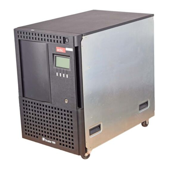
ADIC Scalar 100 User Manual
Quantum scalar 100: user guide
Hide thumbs
Also See for Scalar 100:
- User manual (346 pages) ,
- Quick start manual (2 pages) ,
- Release note (2 pages)
Table of Contents
Advertisement
Quick Links
Download this manual
See also:
User Manual
Advertisement
Table of Contents

Related Manuals for ADIC Scalar 100


Summary of Contents for ADIC Scalar 100
-
Page 1: User Manual
SNC™ 5101 ® for the Scalar User Manual... -
Page 2: Copyright Notice
ADIC • 10 BROWN ROAD • ITHACA, NEW YORK, USA • 1-607-241-4800 ADIC • 11431 WILLOWS ROAD, NE • REDMOND, WASHINGTON, USA • 1-800-336-1233 ADIC • 10949 EAST PEAKVIEW AVENUE • ENGLEWOOD, COLORADO, USA • 1-800-827-3822 ADIC/GRAU Storage Systems GmbH ZAC des Basses Auges Eschenstraße 3 1, rue Alfred de Vigny D-89558 Böhmenkirch, Germany... -
Page 3: Table Of Contents
Table of Contents List of Figures ... ix List of Tables... xiii Notices... 1 ADIC Limited Product Warranty ... 1 ADIC End User License Agreement ... 2 Safety Notices ... 5 Safety Inspection... 6 How to Power Down the SNC ... 6 Environmental Notices and Statements ... - Page 4 Introduction to the ADIC Management Console... 17 Client/Server Model ... 17 Agent ... 17 Server ... 17 Client ... 18 Features... 18 SNMP... 18 SNMP Community Support ... 19 Security ... 19 SAN Access Control ... 19 Host Registration Service... 20 Saved Views...
- Page 5 SNC 5101 Front Panel ... 55 Refresh SNC 5101 Data ... 55 Admin Menu Group... 56 Connect to Server ... 57 Logon ... 57 Change Password ... 57 Logoff... 58 Add New User... 58 Remove User... 59 If You Lose the Password ... 60 Tools Menu Group...
- Page 6 Installing the Host Registration Service... 100 Installing Scalar Firewall Manager... 101 Installation Instructions... 102 Installation Steps for a New SNC ... 102 Installation Steps for an Existing SNC... 109 Entering Host Parameters ... 114 Changing Access Permissions ... 116 Determining LUN Assignments ... 117 Adding and Removing Hosts...
- Page 7 Fibre Channel MAP ... 142 Verify Fibre Channel Connections... 142 Test GBIC ... 142 Examine Cables... 143 Fibre Channel Loop Back Test ... 143 Testing Fibre Channel Optical Cable... 144 Replace Fibre Channel Cable... 144 Replace Fibre Channel Device... 144 SNC MAP ...
- Page 8 Saving a Configuration File ... 166 Loading a Configuration File ... 166 Zmodem Status Code Table ... 167 Setting the Time and Date... 168 Appendix B: Service Port Command Reference ... 171 Appendix C: Diagnostic Command Reference ... 247 Boot Modes... 247 Entering Diagnostic Mode ...
-
Page 9: List Of Figures
List of Figures Figure 1-1: Configuration Overview ... 9 Figure 1-2: Configuration Detail ... 10 Figure 1-3: LEDs ... 14 Figure 1-4: Client Server Model ... 17 Figure 1-5: LED Indicators on Front Panel View ... 21 Figure 2-1: Placement of Thumbscrews on Unit ... 26 Figure 2-2: SCSI Cabling for One Drive and One Channel ... - Page 10 Figure 3-23: Removing a User ... 59 Figure 3-24: Tools Menu ... 60 Figure 3-25: Discover Net ... 60 Figure 3-26: Connect to an SNC ... 61 Figure 3-27: Right-Click Menu: Connect ... 62 Figure 3-28: Disconnect ... 62 Figure 3-29: Right-Click Menu: Disconnect ... 63 Figure 3-30: Health Check Submenu ...
- Page 11 Figure 3-65: Add New Fibre Channel Device ... 88 Figure 3-66: New SCSI Channel Device ... 89 Figure 3-67: Device Mapping Warning ... 89 Figure 3-68: Right-Click Menu: Update Firmware ... 90 Figure 3-69: Update Firmware ... 91 Figure 3-70: Right-Click Menu: Restart ... 91 Figure 3-71: Warning Before Restarting ...
- Page 12 Figure D-11: NMI 2 ... 258 page xii List of Figures...
- Page 13 List of Tables Table 1-1: Fibre Channel Connections ...12 Table 2-1: Pre-Installation Steps ...23 Table 2-2: Installation Steps ...26 Table 2-3: Cabling for Two or Three Drives Over Two Channels ...30 Table 2-4: Cabling for Four Drives over Two Channels ...32 Table 2-5: Cabling for Five or Six drives Over Four Channels ...33 Table 2-6: Post-Installation Steps ...35 Table 3-1: Health Check Levels ...65...
- Page 14 page xiv List of Tables...
-
Page 15: Notices
Notices This manual is intended to provide instruction and reference for the ADIC SNC™ 5101 for the Scalar 100® tape library. ADIC Limited Product Warranty 1. Subject to the limitations set forth below, ADIC warrants to Buyer as follows: a.) For 3 years from the date of delivery to Buyer, all hardware products... -
Page 16: Adic End User License Agreement
party, provided that Buyer notifies ADIC in writing of any such claim within 10 days after learning thereof and that Buyer gives ADIC full control over the defense and set- tlement of the claim and fully cooperates with ADIC with respect thereto. If any such claim is brought or is likely to be brought, ADIC may at its option replace or modify the Products to make them non-infringing, or refund to Buyer, upon the return of the Products at issue, the price paid therefore, less 20% for each year which has passed... - Page 17 of its computers of the same machine architecture, provided that the Software is installed on one (1) Designated Computer at a time. b.) Use. Licensee is authorized hereby to use the Software on one computer only (Designated Computer), or on backup equipment if the Designated Computer is inoperative until such time as the Designated Computer is restored to operation.
- Page 18 d.) Responsibility. Licensee has sole responsibility for use of the products and any information entered, used, or stored thereon, including responsibility for protection of data from modification, destruction, or disclosure, and for the accuracy and integrity of the data. ADIC assumes no responsibility for Licensee's negligence or failure to protect its data.
-
Page 19: Safety Notices
CONSEQUENTIAL DAMAGES OR ANY DAMAGES WHATSOEVER RESULT- ING FROM THE LOSS OF USE, DATA OR PROFITS, RERUN TIME, INACCU- RATE INPUT OR WORK DELAYS, OR ANY PERSONAL OR PROPERTY DAMAGE ARISING OUT OF OR IN CONNECTION WITH THIS LICENSE OR THE USE, PERFORMANCE OR NON-PERFORMANCE OF THE SOFTWARE, WHETHER IN ACTION, IN CONTRACT, OR TORT INCLUDING NEGLI- GENCE, EVEN IF ADIC KNEW, SHOULD HAVE KNOWN OR HAS BEEN... -
Page 20: Safety Inspection
How to Power Down the SNC 1. Perform a controlled system shutdown of attached host systems. 2. Power down the Scalar 100 tape library Environmental Notices and Statements Product Recycling This unit contains recyclable materials. These materials should be recycled where processing sites are available and according to local regulations. -
Page 21: Regulatory Notices
Regulatory Notices SNC CE Notice The Storage Networking component is a DC component and its regulatory compliance hinges on the proper use and installation inside the SC100 library. Installation in any other hardware/application will negate the regulatory compliance for this component and the hardware in which it was installed in. -
Page 22: Copyright Notice
A “Declaration of Conformity” in accordance with the preceding standards has been made and is on file at ADIC Europe, ZAC de Basses Auges, 1, rue Alfred de Vigny, 78112 Fourqueux, FRANCE. Copyright Notice Copyright © 1996-2001 by ADIC. All rights reserved. This document is the property of ADIC. -
Page 23: Chapter 1: Introduction
Features Overview The SNC is the interface between storage and Open System Host interfaces and provides Fibre Channel to SCSI connectivity as well as the ability to manage the library and other devices within the storage network. One possible configuration is illustrated in Figure 1-1. -
Page 24: Configuration Support
Configuration Support The SNC provides two Fibre Channel interfaces. The FC interfaces are configured with Giga Bit Interface Converter (GBIC) modules. In addition, the SNC has four Ultra2 SCSI interfaces. The Ultra2 interfaces are Low Voltage Differential (LVD). See Figure 1-2: Figure 1-2: Configuration Detail Address Mapping The SNC maps addresses across and between these different interfaces and preserves the... -
Page 25: Access Security Capabilities
Therefore, multiple virtual private connections can be created on the same Storage Networking infrastructure. SFM is a Virtual Private connection or channel between a storage element and the user of that element in a Storage Area Network. Scalar Firewall Manager is a method of Access Security that manages the access between an Initiator (user, host, system, ..) to Target/... -
Page 26: Data Mover Module
The Channel Zoning capability is always available to users of the SNC. Data Mover Module The SNC can move data directly between storage devices that are attached to it. This direct movement of data can be from disk to disk, disk to tape, tape to disk or tape to tape. -
Page 27: Ultra2 Scsi I/O Interfaces
that is a Field Replaceable Unit (FRU). See “Removing and Replacing the GBIC” on page 154. Cables should have a duplex SC connector on the GBIC end and a connector appropriate to the HBA in use on the host end. Fibre Channel interfaces support the following Public and Private Loop modes: •... -
Page 28: Ethernet
• The unit provides four SCSI-3 VHDCI connectors for maximum mechanical reliability. The SCSI interfaces are compliant with the following SCSI specifications: • ANSI T10/1071D Rev. 6, SCSI-3 Fast-20 • ANSI T10/375D Rev. 10t, SCSI-2 • ANSI T10/1142D Rev 20b, SCSI-3 Parallel Interface-2 Ethernet The 10/100 Base-T Ethernet port has an RJ-45 connector for out-of-band management. -
Page 29: Supported Platforms
When the SNC is first turned on, some of the LEDs will be on and others will flash while it is booting. The following list briefly describes how to interpret the LED signals. See also “POST Error Codes” on page 255. FC 1-2 •... -
Page 30: Supported Devices
This section contains the physical, electrical, and environmental specifications for the product. The SNC is enclosed in the Scalar 100 tape library. Only the Front Panel of the unit is visible from the back of the Scalar 100. The external dimensions are: •... -
Page 31: Introduction To The Adic Management Console
Introduction to the ADIC Management Console The ADIC Management Console uses a combination of industry-standard Simple Network Management Protocol (SNMP) requests and a method or technology known as SCSI over TCP, which encapsulates SCSI commands and/or data in TCP packets. Client/Server Model Figure 1-4: Client Server Model The ADIC Management Console is part of a three-part client/server model. -
Page 32: Client
TCP, as required. Specifically, the Java Management Application Programming Interface (JMAPI) is used where possible to provide an industry standard and transportable interface. All communication between the Clients and the Server is implemented using the Java Remote Method Invocation (RMI), a form of remote procedure call (RPC). The Server is written to be both transportable and efficient. -
Page 33: Snmp Community Support
SFM manages access permission between any host attached to an SNC SAN connection and any storage element attached to the SNC. This includes storage devices attached to any SCSI Channel and storage devices attached to any other SAN Connection on the SNC. -
Page 34: Host Registration Service
Host Registration Service The Host Registration Service is software that installs on the host from the CD-ROM or it can be downloaded from www.adic.com. It simplifies SFM configuration for the system administrator. It removes the burden of physically tracing each connection to correlate the HBA World Wide Name (WWN) with a specific host. -
Page 35: Event Logging
Event Logging You can retrieve and view the SNC event logs in a table. Filtering based upon the significance of events simplifies fault isolation. For more information, see “Events” on page 65. Health Checks Instantaneous and periodic health checks allow monitoring of each SNC and the devices attached to it. -
Page 36: Heartbeat
Heartbeat Each component of the ADIC Management Console monitors the components with which it communicates to ensure continuity of service. If the SNC is no longer available, the server component notifies monitoring clients. For more information, see “Health Check” on page 63. page 22 Features... -
Page 37: Chapter 2: Installation
Chapter 2: Installation This section covers installation of the SNC, SCSI devices, host adapter, and ADIC Management Console software. ADIC professional services are required for SNC installation. Instructions on how to install the product is divided into three sections: Pre-installation Checklist: Before the service representative installs the SNC, check the items on the Pre- installation Checklist. - Page 38 ° Have been ordered with the product or ° Have been preinstalled and checked ° Are labelled with: ---Host system identifier ---Scalar 100 tape library system identifier. Label both ends of each SCSI cable with: ° Drive ID and SNC connector number.
- Page 39 Table 2-1: Pre-Installation Steps Step Customer Action or Decision Decide on network parameters. Ethernet port configuration decisions: Static IP address____________ Netmask (if required)_________ User-defined SNC name (optional)__________________ If the SNC is not on the same TCP/ IP subnet as the server*, assign the default network gateway address and/or route table entries: ________________________...
-
Page 40: Installation Checklist
Figure 2-1: Placement of Thumbscrews on Unit Installation Checklist The installation checklist has instructions on how to install the SNC with SCSI attached storage and Fibre Channel attached hosts. ADIC professional services are required for SNC installation. Table 2-2: Installation Steps... - Page 41 To connect the SCSI cables appropriately, see “Library and Controller Cabling to Drives” on page 28 Turn on the Scalar 100 tape library. After the Scalar 100 tape library has finished cycling on, issue the targets command from the service terminal.
-
Page 42: Library And Controller Cabling To Drives
Table 2-2: Installation Steps Step Power down the FC host(s). Connect the FC cables from the FC HBA(s) to the SNC . Power up the FC host(s). Issue fcShow command from the service terminal to show the status of the FC interface that is installed and connected. -
Page 43: Figure 2-2: Scsi Cabling For One Drive And One Channel
Figure 2-2: SCSI Cabling for One Drive and One Channel Refer to Figure 2-3 for the most effective Channel Zoning for balancing load across two SCSI Channels. Figure 2-4 shows SCSI Cabling for two Drives over two Channels. Figure 2-5 shows SCSI Cabling for three Drives over two Channels. Table 2-3 summarizes the appropriate SCSI Cabling for one, two, or three Drives over two Channels. -
Page 44: Figure 2-4: Scsi Cabling For Two Drives And Two Channels
Table 2-3: Cabling for Two or Three Drives Over Two Channels Library Drive 1 Drive 2 Drive 3 Figure 2-4: SCSI Cabling for Two Drives and Two Channels page 30 SCSI 1 SCSI 2 SCSI 3 SCSI 4 Installation Checklist... -
Page 45: Figure 2-5: Scsi Cabling For Three Drives And Two Channels
Channels. Figure 2-7 shows four Drives over four Channels as seen from the back of the Scalar 100 tape library. Table 2-5 summarizes the appropriate SCSI Cabling for five or six Drives over four Channels. Figure 2-8 shows cabling for five Drives and four Channels. -
Page 46: Figure 2-7: Scsi Cabling For Four Drives And Two Channels
Table 2-4: Cabling for Four Drives over Two Channels Library Drive 1 Drive 2 Drive 3 Drive 4 Figure 2-7: SCSI Cabling for Four Drives and Two Channels page 32 SCSI 1 SCSI 2 SCSI 3 SCSI 4 Installation Checklist... -
Page 47: Figure 2-8: Scsi Cabling For Five Drives And Three Channels
Table 2-5: Cabling for Five or Six drives Over Four Channels Library Drive 1 Drive 2 Drive 3 Drive 4 Drive 5 Drive 6 Figure 2-8: SCSI Cabling for Five Drives and Three Channels Installation Checklist SCSI 1 SCSI 2 SCSI 3 SCSI 4 page 33... -
Page 48: Figure 2-9: Scsi Cabling For Six Drives And Four Channels
Figure 2-9: SCSI Cabling for Six Drives and Four Channels page 34 Installation Checklist... -
Page 49: Post-Installation Checklist
Post-installation Checklist Perform the actions listed in Table 2-6 after the service representative has completed the installation steps. Table 2-6: Post-Installation Steps Step Install the ADIC Management Console software. For an updated list of supported systems, visit “Service and Support” at www.adic.com. -
Page 50: Other Installation Issues
Become familiar with using the ADIC Management Console. You must use the ADIC Management Console to monitor and maintain your Storage Area Network. If a trap/event is reported by the ADIC Management Console , check the reported event code, then see “Remote Event Notification”... -
Page 51: Installing The San Explorer And Host Registration Service
3. Boot the operating system and install the device driver for the HBA. 4. Reboot and verify that the device driver has started and that expected target devices are seen by the operating system. 5. Install optional utility software, if desired. Perform steps 4 and 5 after the SNC is installed and connected to the host system. -
Page 52: Power-Up And Boot Sequence Guidelines
ADIC Management Console client or from the service terminal. Before you turn on or restart the hosts that are connected to the Scalar 100 tape library, you must wait until the SNC has finished booting. You will know that the SNC has finished booting when the RDY LED on the user panel blinks at intervals of one second. -
Page 53: Installation Requirements
SERVER The system used for the Server does not need to be used as a Client and can be placed in a locked closet. It does need network access to the SNCs it will be managing, so appropriate routes will have to be set on that system and on the SNCs. CLIENT The Client system can be located anywhere, as long as it can connect to the Server system using TCP/IP. -
Page 54: Startup And Configuration
3. The default install option is set to install both the ADIC Management Console Server and Client. When you install the ADIC Management Console on any other attached system, you can opt to install the Client only. Startup and Configuration The first time you install the server component, there is one pre-defined user account, which has administrator privileges. -
Page 55: Figure 2-11: Add New User
To add a new administrator account pull down the Admin menu and click on Add User. See Figure 2-11: Figure 2-11: Add New User Remember that user names and passwords are case sensitive. After you add a new administrator account, the pre-defined user account is deactivated. Attention: Save your administrator account information in a secure location. - Page 56 page 42 Other Installation Issues...
-
Page 57: Chapter 3: Using The Adic Management Console
Chapter 3: Using the ADIC Management Console Menus allow you to select views of one or more SNCs and the devices connected to them, and to perform various actions. From the main screen, six major menu groups are available: • File •... -
Page 58: Figure 3-1: Connect To Server
automatically made when the Client starts. If the Server is on a different system the following dialog is displayed. Figure 3-1: Connect to Server You can enter an IP address or a name if it can be resolved by the Client system. After you connect to the Server, log on. -
Page 59: Tree View
Data Panel on the right. The Tree View in Figure 3-3 is an unexpanded Tree View for a single SNC in a single Scalar 100. For an expanded view, see Figure 3-4. Because the SNC with IP address 192.168.1.182 is selected, it is shown in Tree View with blue highlighting. -
Page 60: Figure 3-4: Expanded Tree View
Tree View is the default view and is selected when the SNC Front Panel option is unchecked. In Tree View, you see icons representing one or more SNCs in a hierarchical tree structure. When you click the node symbol at the left of the ADIC icon, the tree expands to show connected elements represented by other icons. -
Page 61: Fibre Channel Port Modes And Connection Options
The icons used in the Tree View carry specific meaning, both in their design and in their color. See Figure 3-5. Figure 3-5: Icons for Channel Modes and Channel Type In Figure 3-4, Tree View shows Fibre Channel 2 in blue, SCSI Channels 1-4 in green, and Fibre Channel 1 in purple. - Page 62 Public Target and the default connection setting is Loop. From the ADIC Management Console, you can view the settings and change port parameters. Port Mode Options TARGET In this mode, the port operates as a Target allowing a Fibre Channel Initiator (Host or FC switch) to attach to it.
-
Page 63: Figure 3-6: Information About A Selected Channel
LOOP PREFERRED With this connection option, the port operates in Loop mode unless it detects a connection to an N_Port device in which case it automatically switches to Point-to-Point. When a Channel is selected, the lower part of the Data Panel display includes the WWN, port mode, connection type, and maximum speed. -
Page 64: Figure 3-7: Icons Used In Tree View
Figure 3-7: Icons Used in Tree View When a device is selected, information about its capacity, status, width, and speed is all included in the lower portion of the Data Panel. See Figure 3-8. For a list of the different icons used in Tree View, see Figure 3-7. -
Page 65: Figure 3-9: Information About A Selected Host
When a host is selected, information about its WWN, Network Name, Operating System and HBA attachment is all included in the lower portion of the Data Panel. See Figure 3-9. Figure 3-9: Information About a Selected Host No matter what component in Tree View is selected--host, channel, device, or the SNC itself--the top "paragraph"... -
Page 66: File Menu Group
Basement, and then during the course of the session decide to disconnect from the SNC handling Floor 2’s storage, performing a Save Current View only saves a view of the SNCs handling storage connections for the Floor 3 and Basement Scalar 100s. The original view is overwritten by the new view. -
Page 67: Save Current View As
Save Current View as The Save Current View As option saves the currently viewed collection of SNCs on the server. You are prompted to enter a name or short phrase so you can choose to reload the same view in the future. Figure 3-11: Save Current View as Open a Previous View Figure 3-12 is an example list of views previously saved by a user. -
Page 68: Exit
If you press the Close button, the window closes and you are returned to the main screen. Figure 3-12: Saved Views Exit Exit stops the ADIC Management Console Client application and closes its window. Attention: If you exit without selecting a save option after making changes to a view, the changes you made are lost. -
Page 69: View Menu Group
Panel option to see a front-panel view of the selected SNC. The front panel of the SNC is visible from the back of the Scalar 100 tape library. You can see the status of the lights on the front panel of the SNC. The lights are refreshed automatically, about five times per second. -
Page 70: Admin Menu Group
the selected SNC and update all data. This refreshes the data for the SNC and all attached devices. The Refresh SNC 5101 option can also be accessed by right-clicking on Refresh SNC 5101 in the Tree View display. See Figure 3-16. Refresh SNC 5101 is the first of the available right-click options. -
Page 71: Connect To Server
Connect to Server Figure 3-18: Connect To Server To connect to the server, you are prompted to enter the name or IP address of the ADIC Management Console Server system. See Figure 3-18. The status/message line at the bottom of the screen shows whether your connection was successful or unsuccessful. After you have made a successful connection, you can log on. -
Page 72: Logoff
If you do not want to change your password, press Cancel for your old password to remain unchanged. Figure 3-20: Change Password Logoff If you select the Logoff menu item, you will be asked to confirm that you really want to log off. -
Page 73: Remove User
If you decide not to add a new user, press Cancel to return to the main screen. Figure 3-22: Adding a User Remove User You can remove a user if you successfully logged on with administrator privileges. You must enter a valid administrator name and password and then select the name of the user you want to remove. -
Page 74: If You Lose The Password
If You Lose the Password If you lose the administrator password and there is no other user account that has administrator privileges, follow the instructions in the section called “Reactivating the Default Administrator Account” of the Readme file in the appropriate platform software subfolder of the SANMGMT folder on the installation CD-ROM. -
Page 75: Connect
In the Network Address box enter “0” in the place of the subnet you wish to explore, e.g. the entry “192.168.22.0” searches for IP addresses between “192.168.22.0” and “192.168.22.255”. In the Network Mask box enter a subnet mask that matches the class of network you are searching, e.g. -
Page 76: Disconnect
The Connect option of the Tools menu is one of two ways to connect to a particular SNC. You can also right-click the SNC in the Tree View display. See Figure 3-27. Scroll down to the Connect option, which is the second choice in the right-click menu. Figure 3-27: Right-Click Menu: Connect Disconnect The Disconnect SNC 5101 menu choice ends your connection to the selected SNC and... -
Page 77: Health Check
display. See Figure 3-29. The Disconnect option is the third choice in the right-click menu. Figure 3-29: Right-Click Menu: Disconnect Health Check The Health submenus allow you to determine the status of the selected ADIC Management Console. You can also check target devices and controllers. Perform Health Check requests an immediate health check at the current level specified. -
Page 78: Figure 3-31: Right-Click Menu: Perform Health Check
Perform Health Check can also be selected from the right-click menu. See Figure 3-31. In Tree View, select the SNC and then scroll down to the fourth option, Perform Health Check. Figure 3-31: Right-Click Menu: Perform Health Check Figure 3-32: Health Check Setting Options available on the Level tab allow you to choose how thorough the health check will be when it is performed. -
Page 79: Events
Table 3-1: Health Check Levels Level # On the Interval tab you may enter, in minutes, the amount of time that elapses between automatic health checks on the selected SNC. The interval can range from 0 to 65,535 minutes. The default interval is 60 minutes. Check SNC 5101 Heartbeat performs a simple communication check on the selected SNC. -
Page 80: Figure 3-34: Event Reporting Level
the selected level will be displayed. The most recent events are displayed at the top of the list. Selecting Warning will display Warning and Notice events. Figure 3-34: Event Reporting Level Selecting Information will display Information, Warning and Notice events. Figure 3- 35 contains the contents of a typical Event Log. -
Page 81: Figure 3-36: Saving An Event Log
Save Event Log allows you to save a copy of the currently displayed entries of the selected SNC event log to a text file. From the browser dialog, you enter a name for the file and the location where you want to save it. Figure 3-36 shows the browser dialog. Figure 3-36: Saving an Event Log After saving the log, you have an option that clears the whole Event Log on the selected SNC. -
Page 82: Figure 3-38: Event Trap Thresholds
Figure 3-38: Event Trap Thresholds A threshold level of zero disables traps for that event. A threshold level of one means that a trap is sent each time the event occurs. Any other value (up to 255) specifies how many times the event can occur in a ten-minute period;... -
Page 83: Figure 3-39: Change Event Threshold Dialog Box
must occur within a ten-minute period or no trap will be issued. The Fibre Channel LIP is the only event that has its threshold level set to something other than 1. Figure 3-39: Change Event Threshold Dialog Box Receive Event Traps is the last option on the Events submenu. It controls whether your ADIC Management Console client receives trap notifications for the SNCs you are monitoring in your current view. -
Page 84: Save Snc 5101 Configuration
is connected to a server. You can Minimize the window but you cannot close it. You can double-click on an event in the window to display more detailed information. Figure 3-40: Event Trap Window In the example above, the Event Trap window contains some typical Health Check events. You can see, for example, that the server at 192.168.30.200 was not online on August 2, 2001 at 4:46 p.m. -
Page 85: Load Snc 5101 Configuration
Attention: It is important that you save the configuration of each SNC initially and any time there is a change in the device address maps. It is a good idea to save the configuration locally and on the Server to ensure that you have access to the file. -
Page 86: Controls Menu Group
Figure 3-44: Loading a Configuration From the Server Attention: If you replace the SNC and do not load the saved configuration, you might not be able to use the storage devices attached to the SNC or data may be lost. -
Page 87: Feature Enable
Scalar Firewall Manager allows you to control access permission between FC hosts (HBAs) and storage devices (Target LUNs) attached to the SNC. If you need to enable this feature, you must have the License Key that corresponds to the serial number of your SNC. -
Page 88: Feature Enable: Data Mover Module
The Data Mover Module allows you to use Server-Free tape backup applications that support SNIA Extended SCSI Copy. This feature allows the SNC to move blocks of data directly between storage devices attached to the SNC. It is already enabled. Access Options Use this menu if you want to view or configure Access Control settings for the selected SNC. -
Page 89: Figure 3-49: Right-Click Menu: Channel Zoning
See Figure 3-49. Channel Zoning is the fifth option on the right-click menu. Channel Zoning does not need to be Enabled before you use it. Figure 3-49: Right-Click Menu: Channel Zoning Channel or “Port” zoning configures access to all the LUNs on a particular SCSI channel for the exclusive use of a host or group of hosts on a single Fibre Channel. -
Page 90: Access Options: Scalar Firewall Manager
Scalar Firewall Manager provides you with a finer degree of access control between host bus adapters in individual systems and Target LUNS on storage devices. SFM can be used to allow multiple Fibre Channel hosts connected directly or via switches and hubs to be able to share the same SCSI or Fibre Channels while restricting their access to selected LUNs. -
Page 91: Figure 3-51: Right-Click Menu: Scalar Firewall Manager
menu. See Figure 3-51. Scalar Firewall Manager is the sixth option on the right-click menu. Figure 3-51: Right-Click Menu: Scalar Firewall Manager Attention: If you did not use Channel Zoning to restrict access between SAN connections and SCSI Channels, SFM has full control of all SAN and SCSI Channels. -
Page 92: Figure 3-52: Scalar Firewall Manager Access Settings
Figure 3-52: Scalar Firewall Manager Access Settings You can press the Close button to close the window. If you made changes, a confirmation box will present you with the option of not closing until you apply the changes. Pressing the Apply Changes button keeps the changes you made to host data fields and LUN assignments. -
Page 93: Snmp Community Strings
SNMP Community Strings This menu option will display a dialog (Figure 3-53) that allows you to modify the SNMP community strings for the ADIC Management Console. They are stored on the Server. Figure 3-53: SNMP Community Strings SNMP community strings serve to group network devices into logical collections for management purposes. -
Page 94: Figure 3-54: Right-Click Menu: Scsi Channel Parameters
54. Unless you have selected a SCSI channel in Tree View, the SCSI Channel option will be grayed out. Figure 3-54: Right-Click Menu: SCSI Channel Parameters Attention: If you change any of the SCSI Channel Parameter settings, you have to reset the SCSI channel or reboot the SNC to use the new settings. Figure 3-55: SCSI Channel Controls: Target to Initiator The SCSI Channel settings window gives you the opportunity to change a number of different settings. -
Page 95: Figure 3-56: First Scsi Reset Warning
Bus Reset on Power Up is typically enabled. Removing the check mark from this box disables SCSI bus reset on power-up. Enable Termination is typically enabled. Removing the check mark from this box disables the internal termination circuits. The default Alternate Initiator ID is set automatically by the SNC. When the SNC scans the SCSI Bus, it determines which IDs are currently being used by target devices and sets the Alternate ID to the highest ID not in use. -
Page 96: Fibre Channel
Figure 3-57: Second SCSI Reset Warning Fibre Channel Fibre Channel shows you parameters for the selected Fibre Channel interface. If you have administrator privileges, you can change the settings by selecting the Channel in Tree View and then going to Controls > Fibre Channel. You may also access the Fibre Channel Parameters dialog box by selecting the Channel in Tree View and then using the right-click menu. -
Page 97: Figure 3-59: Fibre Channel Default Settings
The default Loop ID setting is Soft and should typically not be changed. (It may be appropriate to use another Loop ID setting when using Fibre Channel switches). If you remove the check mark from the box, you can enter a loop ID value from 0 to 125. Frame Size has three possible values: 512, 1024, and 2048. -
Page 98: Device Mapping
Device Mapping Using the ADIC Management Console, you can edit the SNC’s persistent address map database and customize the LUN assignment for each target device. Select the SNC in Tree View and then select Device Mapping from the Controls pull-down menu. You may also access the Device Mapping dialog box via the right-click menu. -
Page 99: Figure 3-61: Devices Available For Mapping
Figure 3-61: Devices Available for Mapping In Figure 3-61, several SCSI devices are displayed, one of which is on SCSI Channel 4 of the SNC at 192.168.1.182. The Target ID of the selected tape device is 4, its Device LUN is 0, and its Assigned LUN is 10. -
Page 100: Figure 3-62: Device Mapping Window
From the ADIC Management Console, select the SNC. Figure 3-62: Device Mapping Window As shown in Figure 3-62, devices that have already been entered into the persistent device map appear in black type on the left. The Device Mapping Window uses the format Channel [Target ID:Device LUN] after the Channel type, SCSI or Fibre. -
Page 101: Pre-Assigning Device Numbers
than the devices on SCSI 2. When you are satisfied with the assignments that have been made, press OK. If you decide not to make any changes, press Cancel. Figure 3-63: Devices That Have Been Remapped From the ADIC Management Console, select the SNC, then from the Controls menu, choose Restart SNC. -
Page 102: Figure 3-64: Add New Scsi Device
The default device type is SCSI, see Figure 3-64. Fill in the desired Channel Number, Target ID and LUN Number for a SCSI device. Figure 3-64: Add New SCSI Device If the device to be added is a Fibre Channel device, use the pull-down to select Fibre, and then fill in the desired LUN and the WWN of the device, if known. -
Page 103: Figure 3-66: New Scsi Channel Device
connected to SCSI Channel 1. It will have a target ID of 0 and a LUN of 0. It appears in the right-hand column of the Device Mapping screen. See Figure 3-66. Figure 3-66: New SCSI Channel Device Make sure that each device in the right-hand column is mapped to a LUN in the left-hand column, or the Device Mapping window will not close. -
Page 104: Update Firmware
Update Firmware With the SNC selected in Tree View, you can use the Controls > Update Firmware option to update operational firmware or you can use it to send micro-code to SCSI target devices as a means to update their firmware. You can also access the Update Firmware file browser by using the right-click menu. -
Page 105: Restart Snc 5101
the SNC to use the new firmware. Figure 3-69: Update Firmware Restart SNC 5101 After you select an SNC in Tree View, you can use the Controls > Restart SNC 5101 option to reboot it. You can also reboot a selected SNC via the right-click menu. See Figure 3-70. -
Page 106: Identify Snc 5101
When you select Restart SNC 5101, the following message is displayed: Figure 3-71: Warning Before Restarting Identify SNC 5101 Identify SNC 5101 allows you to visually identify the selected SNC. Pressing the Turn Ready LED On button makes the RDY light flash rapidly. See Figure 3-72. For the position of the RDY LED, see “LED Indicators”... -
Page 107: Figure 3-73: Viewing Events In The Event Log
Level 0 events are displayed by the Client only when the viewing level is set to All Events. See Table 3-2. Table 3-2: Event Viewing Levels Level Name Notice Warning Information Private Figure 3-73: Viewing Events in the Event Log Remote Events and Notifications Explanation Conditions that should always be reported, such as tempera-... -
Page 108: Events And Traps
Events and Traps Events are recorded in the SNC event log. For each event, an assigned Viewing Level corresponds with the event log facility available to the Client application (all events are recorded in the SNC log regardless of the assigned level). A Trap Threshold is preset for each event so that when the number of instances of that event reaches the threshold, a trap will be sent. -
Page 109: Health Check
While an SNC is being monitored, the Server application periodically attempts to communicate with it (every two minutes). A fault is reported to any interested Client if an SNC is no longer available. While a Client is connected to a Server, the Client periodically tests the connection to the Server to make sure it is still available. -
Page 110: Health Check Level Control
Figure 3-75: Successful Health Check Health Check is enabled when the level is set to a value greater than 0. This can be set from the Client application or from the service terminal. Health Check Level Control The Health Check level may be set to the levels described below using the ADIC Management Console. - Page 111 1 — Basic Function When set to the “Basic Function” level, the SNC periodically scans the system resources to locate problems. Health Check status will be set if either of the following conditions is true: Temperature Sensors detect WARNING or ALARM status Power Supply sensors detect a change in status since the last report.
-
Page 112: Health Check Interval
Health Check Interval The Health Check interval controls how often the Health Check process runs. The interval may range from 1 to 65,535 minutes. The default setting is 60 minutes. See Figure 3-76. Figure 3-76: Health Check Interval Performance Impact of Health Checks At higher levels (3 or 4), the Health Check process may interfere with high demand I/O operations. -
Page 113: Chapter 4: Scalar Firewall Manager
(an optional automatic Host Registration Service that provides periodic host status information is included). It has no interface dependencies and supports Fibre Channel, SCSI or any other SAN interface. It is also independent of the storage elements and requires no change in legacy or new storage devices. -
Page 114: Host Registration
Any HBA (or Initiator) that is added to a SAN connection at a later time will only have access to the SNC Command and Control LUN. In this case, the system administrator must explicitly set access privileges to the desired storage element for each host connection. -
Page 115: Installing Scalar Firewall Manager
It is important for the system administrator to know whether hosts are online or offline when configuring SFM access settings. A Host Registration Service is provided to simplify SFM configuration and it allows the system administrator to monitor host status. It removes the burden of physically tracing each connection to correlate the Fibre Channel HBA WWN with a specific host. -
Page 116: Installation Instructions
“Installation Steps for an Existing SNC” on page 109. Installation Steps for a New SNC Note: This procedure assumes that the Scalar 100 and the SNC are finished booting, and that the ADIC Management Console software has already been installed. -
Page 117: Figure 4-1: One Registered Host Online
9. Startup one of the hosts and wait for it to finish booting. From the SNC, select the SNC. From the View menu, select Refresh SNC 5101 Data. 10. After the SNC has been refreshed, expand the tree to show tree elements. Expand the tree for the Fibre Channel that the host is connected to and verify that the registered host is displayed. -
Page 118: Figure 4-3: Confirming That Two Registered Hosts Are Online
11. Repeat steps 8 and 9 until all hosts are displayed. Figure 4-3 is an example that shows how two registered hosts, Collie and Timberline, are displayed. Because Timberline is selected, information about it appears in the Data Panel. Figure 4-3: Confirming That Two Registered Hosts are Online page 104 Installing Scalar Firewall Manager... -
Page 119: Figure 4-4: Determining The Assigned Lun
12. Expand the tree to display storage devices and determine their Assigned LUNs. Figure 4-4 shows the Assigned LUN for the selected SCSI device on SCSI Channel 4. Figure 4-4: Determining the Assigned LUN The Assigned LUN for the selected device is displayed in the first line of the Disk Device description area. -
Page 120: Figure 4-5: Initial Sfm Window Before Access Assignments
14. From the ADIC Management Console, select the SNC. From the Controls menu, select Access Options > Scalar Firewall Manager. Figure 4-5 shows a Scalar Firewall Manager window that does not yet have any access settings. Figure 4-5: Initial SFM Window Before Access Assignments Registered hosts are shown in the column on the left. -
Page 121: Figure 4-6: Sfm Host Parameters Pop-Up
After you have selected a certain host, and its parameters are displayed at the bottom of the window, you can still see parameters for another host by hovering the mouse over the other host’s name. A pop-up with host parameters will appear. See Figure 4-6. Figure 4-6: SFM Host Parameters Pop-Up 15. -
Page 122: Figure 4-7: Assigning Host Access Permissions
Figure 4-7: Assigning Host Access Permissions For more information about the device at a specific LUN, you can hover the mouse over the Assigned LUN number in the header row. See Figure 4-8. The pop-up will state the Channel Number, Target ID and Device LUN, product ID, vendor ID, and serial number of the device. -
Page 123: Installation Steps For An Existing Snc
19. Save your configuration, as explained in “Save SNC 5101 Configuration” on page 70. Installation Steps for an Existing SNC Note: This procedure assumes that the storage devices, SNC and hosts are turned on and the ADIC Management Console software has already been installed. - Page 124 Otherwise, if you have changed Channel Zoning settings to create restricted access zones, confirm that you want to keep those settings and restrictions. If you want to keep those settings, go to step 2. You can use a combination of Channel Zoning and SFM but SFM can only control access permissions between devices in the same access zone.
-
Page 125: Figure 4-9: Two Hosts Online
7. After the SNC has been refreshed, expand the tree to show tree elements. Expand the tree for the Fibre Channels and verify that all registered hosts are displayed. Figure 4- 9 is an example that shows how registered hosts are displayed. Figure 4-9: Two Hosts Online In the Tree View panel of Figure 4-9, you can see that hosts are connected to the SNC Fibre Channel ports 1 and 2. -
Page 126: Figure 4-11: Checking Access Settings Inherited From Hosts
LUN is on and see how the SNC has made LUN assignments by pressing the Close button and going back to the main screen. Expand the tree to display SCSI or Fibre Channel storage devices and determine their Assigned LUNs. Figure 4-12 shows the Assigned LUN for... -
Page 127: Figure 4-12: Checking The Assigned Lun
the selected SCSI device on SCSI Channel 4. Figure 4-12: Checking the Assigned LUN The Assigned LUN for the selected device is displayed in the first line of the Disk Device description area. In the above example, the assigned LUN for the selected disk device is 10. -
Page 128: Entering Host Parameters
Entering Host Parameters You may need to manually enter host parameters if the Host Registration Service is not installed or when automatic host registration is not available for a specific host type (for example, to register a Fibre Channel switch). When you see the WWN of the host in the SFM Access Settings window and the other fields are shown as “unknown”... -
Page 129: Figure 4-14: Entering Parameters For A Fibre Channel Switch
Host Name: Usually the name of the computer on the Local Area Network (LAN). System administrators use this name to refer to the host. Host Type: The type of host, version of the operating system software and the Service Pack Level (NT/Windows 2000) or patch level (e.g., Solaris, AIX). Otherwise, Host Type can be the type of network appliance, switch, bridge, etc. -
Page 130: Changing Access Permissions
Changing Access Permissions Attention: Ensure that the host is not accessing the device LUN if you intend to remove its access privileges. If possible, unmount the file system or shutdown the host before removing access. If you give shared access to a LUN, ensure that some other software will manage device sharing. -
Page 131: Determining Lun Assignments
Determining LUN Assignments You can expand the tree to display SCSI Channel storage devices and determine their assigned LUNs. Figure 4-16 shows the Assigned LUN for the selected SCSI device on SCSI Channel 4. -
Page 132: Adding And Removing Hosts
The Assigned LUN is displayed below Disk Device description on the right side of the screen. In the above example, the assigned LUN for the selected disk device is 10. Adding and Removing Hosts After SFM is already enabled, you may want to add a Host (or Initiator) to the SAN configuration or remove it from the SAN configuration. -
Page 133: Figure 4-17: Adding A New Host
Adding a Host Before Attaching it to the SAN You can add a host that has not yet been attached to the SAN and configure its access permissions beforehand. You add the host by pressing the New Host button in the SFM Access Settings window and manually entering the WWN and other parameters as shown in Figure 4-17. -
Page 134: Combining Sfm With Channel Zoning
2. Refer to the section “Changing Access Permissions” on page 116 to assign access permissions for the new host. 3. When you are ready to attach the new Host to the SAN, go to the section “Attaching a New Host to the SAN” on page 118. Removing a Host from the SAN Configuration You may want to remove a host from the SFM database. -
Page 135: Chapter 5: Maintenance Action Plans
Chapter 5: Maintenance Action Plans This section describes the Maintenance Action Plans (MAPs) for the SNC. MAPs exist for all of the SNC’s component systems. If it is clear that a particular component system is at fault in a problem situation, you may go directly to the MAP for that component by consulting Table 5-1 below. -
Page 136: Service Reference Table
Service Reference Table Review all visual observations and event codes against the following table. Numerical equivalents for the Event Viewing Levels are shown in Table 5-2: “Event Viewing Levels” on page 122. Table 5-2: Event Viewing Levels Number Level Notice Warning Information Default Trap Threshold settings, displayed in column 3 of Table 5-3: “Service Reference... - Page 137 Table 5-3: Service Reference Table Event Viewing Code Level N.A. N.A. N.A. N.A. N.A. N.A. N.A. N.A. N.A. N.A. N.A. N.A. N.A. N.A. N.A. N.A. N.A. N.A. N.A. N.A. N.A. N.A. N.A. N.A. N.A. N.A. Service Reference Table Default Trap Description Threshold Visual Observations...
- Page 138 Table 5-3: Service Reference Table Event Viewing Code Level page 124 Default Trap Description Threshold ADIC Management Console reports a temperature change (event message indicates the change to High, Very High, Reduced, to High, or OK SNC is shutting down as requested by the ADIC Management Console (a Restart was requested)
- Page 139 Table 5-3: Service Reference Table Event Viewing Code Level Service Reference Table Default Trap Description Threshold A SCSI bus reports a reset has been detected SNC has added a device to its configuration table NOTE: The trap is held off until the SNC has been up for 60 seconds SNC has removed a device from its configuration...
- Page 140 Table 5-3: Service Reference Table Event Viewing Code Level page 126 Default Trap Description Threshold Fibre Channel interface driver reported debug file dump (event log contains further information) Power has returned to Nominal from Warning or Alarm Stage Power has entered Warning Range from Nominal Range (Power falling) or Alarm Range (Power improving)
- Page 141 Table 5-3: Service Reference Table Event Viewing Code Level Service Reference Table Default Trap Description Threshold SNC restart completed Maximum number of initiators has been exceeded The event log is about to overwrite the earliest events Health Check Event Descriptions Power supply is out of specification Temperature change detected since the last report (event message...
-
Page 142: Table 5-4: Action Reference Table
Table 5-3: Service Reference Table Event Viewing Code Level N.A. N.A. N.A. N.A. Footnotes Check the Event Log to find out which interface (FCAL or SCSI) caused this event. Then use the appropriate action number. This trap signals a change in state. A string sent with the trap will indicate the nature of the previous state. -
Page 143: Start Map
Start MAP Gather as much information as possible before performing a repair action. When gathering information, you may need to connect the service terminal to the service port. See "Appendix A: Connecting to the Service Port". For the latest information on the SNC, see “Service and Support” at www.adic.com. Event Code or Obvious Symptom Either an Event Code has been reported by the ADIC Management Console or an error has been observed by other means. -
Page 144: Check Snc Product Versions
• Operating system version • Service pack version • Hot-fix version • HBA hardware version • HBA firmware version • HBA device driver version If an update is required, perform the update. Check SNC Product Versions For an updated list of required updates, see “Service and Support” at www.adic.com. If the ADIC Management Console application is in use, use the Help >... -
Page 145: Quick Component Check
Check the event codes against the “Service Reference Table”on page 123. If there are no abnormal events, go to “Perform Health Check” on page 131. If the client application is not available, use the loggerDumpCurrent 2 command from the service terminal. See the "loggerDump [number]" command on page 207. Check the event codes against the “Service Reference Table”... -
Page 146: Device Access Map
If the database has no room for a newly detected device, the new device will not be mapped (assigned a LUN). The database can become full if there are more devices attached than there were previously or if devices were moved to different ports or channels. -
Page 147: Check Fibre Channel Port Status
Check Fibre Channel Port Status 1. Enter the fcShow command from the service terminal (see “Service Port Command Reference” on page 171). If the fcShow command does not display a Firmware State of Ready for the attached Fibre Channel SAN connections, go to “Fibre Channel MAP”... -
Page 148: Scsi Map
2. If you are running Scalar Firewall Manager use the ADIC Management Console to open Controls > Access Options > Scalar Firewall Manager menu and verify the host and target device access settings. 3. Restart the hosts and verify that each host can access the devices that have been assigned by SFM. -
Page 149: Check Attached Scsi Devices From The Service Port
Check SCSI Bus Termination Attention: If in this procedure you determine that you need to remove a SCSI cable or terminator, all I/O to the SNC must be stopped and the Scalar 100 must be turned off. For each SCSI device attached to the questionable SCSI channel: 1. -
Page 150: Check For Multiple Scsi Ids
3. Excessive termination: Check that all SCSI devices other than the end devices have internal termination disabled. 4. If SCSI termination is OK, go to “Check for Multiple SCSI IDs” below. 5. If you powered the Scalar 100 down in order to correct a SCSI termination problem, turn it back on. •... -
Page 151: Improper Device Type
Examine SCSI Cables Attention: If in this procedure you determine that you need to remove a SCSI cable, all I/O to the SNC must be stopped and the Scalar 100 must be turned off. 1. Look for damaged cables. Check for breaks in the cable jacket, exposed or frayed cable shield, exposed or broken wires. -
Page 152: Examine Scsi Connectors
If you did not have to replace or re-secure a SCSI cable, go to “SCSI Loop Back Test”. 3. If you replaced or re-secured a SCSI cable, turn on the Scalar 100. 4. After the SNC finishes booting, enter the scsiShow command from the service terminal. -
Page 153: Scsi Loop Back Test
5. Connect a short SCSI loopback test cable to those two SCSI channels. An appropriate SCSI loopback cable is included in the CE Tool Kit. 6. Power on the system. Wait for the SNC and the Scalar 100 to finish booting. The Scalar 100 takes longer to boot than the SNC does. -
Page 154: Isolating Scsi Devices
(refer to the list made in “Check for Multiple SCSI IDs” on page 136) using a known-good SCSI cable and terminators. 6. Power the Scalar 100 back on. Wait for it and the SNC to finish booting. The Scalar 100 takes longer to boot than the SNC does. -
Page 155: Restore Scsi Setup
2. Reconnect all available SCSI devices to their proper channel assignments (either their original configuration, or with any changes made per this MAP). 3. Wait for the SNC and the Scalar 100 to finish booting. The Scalar 100 takes longer to boot than the SNC does. -
Page 156: Fibre Channel Map
Fibre Channel MAP These steps are performed if • The Fibre Channel interface reports a reset or system error • The Fibre Channel interface reports an error processing a request or response • The Fibre Channel interface reports an excess of 10 LIPs in a 10-minute interval •... -
Page 157: Examine Cables
• Go to “Examine Cables” below. Examine Cables Attention: If in this procedure, you need to remove or replace the Fibre Channel cable, you must stop I/O at the Fibre Channel host. 1. Remove the cables. 2. If any cables are obviously damaged, replace them. 3. -
Page 158: Testing Fibre Channel Optical Cable
Testing Fibre Channel Optical Cable Note: If the Fibre Channel cable is extremely long it may be more practical to replace the Fibre Channel device first; then if the problem is not resolved, replace the cable. 1. If the cables are already removed, reattach them. •... -
Page 159: Snc Map
The Server could not verify the connection to the SNC Observe Operational LED Behavior When the Scalar 100 is first powered on, the front-panel’s LEDs flash a variety of patterns as it performs the Power On Self Test (POST) and then starts booting. Within one minute, the SNC should have booted successfully and the Ready LED should be blinking once per second. -
Page 160: Temperature Warnings Or Alarms Received
command on page 185 for operational temperature ranges that will generate these messages. If the temperature problems are due to a reduction in blower functionality, Event Codes 62, 63, 64, or 65 will be accompanied by Event Codes 67 or 68. See the "envMonRangeShow"... -
Page 161: Power Map
Health Check generates a Trap Event Code 113, indicating that Power is running in Warning or Alarm Range 1. Verify that Scalar 100 is plugged into an active AC power source. 2. Verify the status of the SNC Power LED. If the Power LED remains off, go to “Removing the SNC”... - Page 162 2. Verify that the Ethernet Link LED, which is the green LED on the left, is on. • If the LED is on, go to step 3. • If it is not on, go to “Preparing for Removal and Replacement of the SNC” on page 154.
- Page 163 11. From the service terminal, enter the ifShow command. See “Service Port Command Reference” on page 171. SN600752 > ifShow ibmEmac (unit number 0): Flags: (0x8063) UP BROADCAST MULTICAST ARP RUNNING Type: ETHERNET_CSMACD Internet address: 172.16.76.211 Broadcast address: 172.16.255.255 Netmask 0xffff0000 Subnetmask 0xffff0000 Ethernet address is 00:60:45:17:02:f0 Metric is 0 Maximum Transfer Unit size is 1500...
- Page 164 15. Otherwise, use the ethAddrSet command to set the correct IP address and netmask values See the"ethAddrSet" command on page 188. • From the service terminal, enter the reboot command and wait for the SNC to finish booting. • Go back to step 11. 16.
- Page 165 19. From the service port, enter the elTest command. diagmode > elTest ==== Testing Ethernet ==== Init complete. Ethernet OK value = 0 = 0x0 20. If the test failed, replace the SNC. • Go to “Preparing for Removal and Replacement of the SNC” on page 154. •...
-
Page 166: Service Port Map
1. Reconnect the terminal to the SNC with the RS-232 null modem cable. 2. Stop all I/O to the SNC. 3. Perform a graceful shutdown of the Scalar 100 and keep the power off for 5 seconds. Then turn it back on. -
Page 167: Chapter 6: Removal And Replacement Procedures
Chapter 6: Removal and Replacement Procedures This section describes the removal and replacement procedures for the SNC in its entirety or for one or more of its GBICs. Handling Electrostatic Discharge-Sensitive Parts Attention: It is highly recommended that you follow industry best practice when handling Electro Static Discharge (ESD) Sensitive Parts. -
Page 168: Removing And Replacing The Gbic
SNC has stopped. 1. Verify that the latest configuration has been saved. • See “Save SNC 5101 Configuration” on page 70. 2. Perform a graceful shutdown of the Scalar 100 and disconnect the power cord. page 154 Removing and Replacing the GBIC... -
Page 169: Removing And Replacing The Snc
For ESD information, see “Handling Electrostatic Discharge- Sensitive Parts” on page 153. This procedure describes how to remove and replace the SNC from the Scalar 100. Removing the SNC 1. Complete all steps in “Preparing for Removal and Replacement of the SNC” on page 154. -
Page 170: Final Test Preparation
1. Attach the service terminal to the SNC. 2. Reattach the power cord to the Scalar 100. 3. Turn on the Scalar 100 and wait until it and the SNC have finished booting. The SNC finishes booting before the Scalar 100 finishes. -
Page 171: Ethernet Test
2. From the service terminal, enter the scsiChannelTest 1,2 command. 3. If the test passed, remove the loop back cable and go to “Test SCSI Port 3 and 4”. If not, go to “Start MAP” on page 129. Test SCSI Port 3 and 4 1. -
Page 172: Figure 6-1: Ethernet Port
connection to the Ethernet. See Figure 6-1. You will need to first configure the IP address by connecting a terminal or terminal emulator to the Service Port of the SNC. Figure 6-1: Ethernet Port To configure the network, connect to the SNC Service Port. See "Appendix A: Connecting to the Service Port". -
Page 173: Updating The Snc
• If a network gateway is needed for the SNC to communicate with other systems, you must specify one. foster > gateAddrSet "192.168.1.1" value = 0 = 0x0 • When more complicated routing is required to reach the ADIC Management Con- sole server, use the route command to specify the destination address, as a full address (single host) or as an abbreviated subnet address. -
Page 174: Post-Repair Checklist
Attention: You must perform this step if you replaced the SNC. See “Service Port Command Reference” on page 171. 6. Perform a graceful shutdown of the Scalar 100 and unplug the power cord. 7. Disconnect the RS-232 cable from the SNC. - Page 175 Table 6-1: Post-Repair Checklist Step Actions If you replaced the SNC, configure the network parameters. Perform the following: Start the ADIC Management Console server and client, logon with administrator privileges and connect to the SNC If you downloaded new operating software in Step 5, use the Controls >...
- Page 176 Table 6-1: Post-Repair Checklist Step Actions From the service terminal, enter the fcShow command to show the status of each FC interface that is installed and connected. From the service terminal, enter the fcShowDevs command to show the SCSI target devices that are connected as seen by the Fibre Channel interface.
-
Page 177: Appendix A: Connecting To The Service Port
Appendix A: Connecting to the Service Port The service port is an RS-232C Data Terminal Equipment (DTE) port, configured at 19200 Baud, with 8 data bits, no parity and hardware flow control. The 9-pin connector is compatible with serial ports on PCs. A PC may be used to connect to the service port, using a 9-pin to 9-pin null modem cable. -
Page 178: Connecting The Service Terminal
Table A-2 lists the null modem cable connections. Table A-2: Null Modem Cable Connections Service Port Pin Number Carrier detect (not used) Data terminal ready <-> Data set ready <-> Data terminal ready Request to send <-> Ring indicator (not used) Connecting the Service Terminal ARDWARE EQUIRED... -
Page 179: Verifying The Connection
2. Turn on the service terminal. 3. On the service terminal, select the HyperTerminal icon and double-click on it. 4. In the New Connection dialog enter SNC for the name and click OK. 5. In the Connect To dialog, for the Connect using field select the COM Port number that you have chosen and click OK. -
Page 180: Updating Snc Firmware
Updating SNC Firmware 1. From the Hyper Terminal window, at the SN60023 > command prompt, type rz and then press the Enter key. 2. From the HyperTerminal window select Transfer and Send File. 3. From the Send File dialog enter the path and filename where the firmware file is located or click the Browse button and navigate to it. -
Page 181: Zmodem Status Code Table
2. From the HyperTerminal window select Transfer and Send File. 3. From the Send File dialog enter the path and file name where the firmware file is located or click the Browse button and navigate to it. In the Protocol field, select Zmodem and click the Send button. -
Page 182: Setting The Time And Date
Table A-3: Zmodem Status Codes Status Description Code Setting the Time and Date ETTING THE 1. Use the rtcDateSet command to manually set the Real Time Clock. See the "rtcDateSet[year],[month],[dayofmonth],[dayofweek], [hour],[minute],[second]" command on page 217: SN60023 > rtcDateSet 2001,1,26,5,9,30,00 value = 0 = 0x0 SN60023 >... - Page 183 DDING A YSTEM 1. To enable the timeserver functionality use the setNettime command. See the "setNettime [value]" command on page 225): SN60023 > setNettime 1 Nettime 1 value = 0 = 0x0 SN60023 > 2. Add a Host running timeserver to the SNC using the setTimeHost command. See the "setTimeHost"...
- Page 184 YNCHRONIZING THE IMESERVER 1. Add a Host running timeserver to the SNC using the setTimeHost command. See the "setTimeHost" command on page 226: SN60023 > setTimeHost “butter” Time Host butter value = 0 = 0x0 SN60023 > 2. Synchronize the SNC’s Real Time Clock with the timeserver using the rtcSetCurrent command: SN60023 >...
-
Page 185: Appendix B: Service Port Command Reference
Appendix B: Service Port Command Reference A “shell” interface provides access to management and configuration commands. The shell is accessible by connecting a terminal or computer with terminal emulation software to the SNC’s Service Port. The ADIC Management Console application should be used for managing the SNC. When you use the ADIC Management Console, most of the operations described in this reference will be carried out through the client application. - Page 186 Table B-1: Commands Grouped by Function Command or Command Group Ethernet Network arptabShow ethAddrGet ethAddrSet gateAddrGet gateAddrSet host “ add ” host “ delete ” host “ list ” hostNameSet icmpstatShow ifShow inetstatShow ipstatShow macShow mbufShow route route “ add ” page 172 Description Display a list of known ARP...
- Page 187 Table B-1: Commands Grouped by Function Command or Command Group route “ delete ” route “ list ” snmpCommunitiesShow snmpReadCommunityAdd snmpReadCommunityRemove snmpTrapCommunitySet snmpWriteCommunityAdd snmpWriteCommunityRemove tcpstatShow trapDestAdd trapDestRemove trapDestShow udpstatShow userAdd userDelete userList Commands Grouped by Function Description Delete network route table entries List network route table entries...
- Page 188 Table B-1: Commands Grouped by Function Command or Command Group Event Logging cleShow cleShowAll csClearLogFile loggerDump loggerDumpCurrent supportDump Fibre Channel fcConnTypeGet fcConnTypeSet fcFibreSpeedGet fcFibreSpeedSet fcGbicShow fcPortModeGet fcPortModeSet fcRestart page 174 Description Display Command Log events for the specified LUN Display Command Log events for all LUNs Clear the Event Log Display Event Log records...
- Page 189 Table B-1: Commands Grouped by Function Command or Command Group fcShow fcShowDevs fcShowNames fcTxDisable fcTxEnable setFcFrameSize setFcHardId setHost sysNodeNameModeSet sysNodeNameModeShow targets Flash File System Commands Grouped by Function Description Display Fibre Channel interface status Display attached SCSI and Fibre Channel Target Devices from Fibre Channel port perspective Display Node and Port...
- Page 190 Table B-1: Commands Grouped by Function Command or Command Group Health Check hlthChkIntervalGet hlthChkIntervalSet hlthChkLevelGet hlthChkLevelSet hlthChkNow Help clehelp diagHelp help hlthChkhelp mapHelp netHelp snmpHelp userHelp page 176 Description Remove (delete) a file Initiate a receive Zmodem file transfer session Initiate a send Zmodem file transfer session Display Health Check...
- Page 191 Table B-1: Commands Grouped by Function Command or Command Group Product Data and Maintenance clearReservation initializeBox licenseShow mapCompressDatabase mapRebuildDatabase mapShowDatabase mapShowDevs mapWinnowDatabase shellLock showBox Commands Grouped by Function Description Force-clear a reservation on the specified target Restore factory defaults by deleting all configuration files including persistent address map and SFM...
- Page 192 Table B-1: Commands Grouped by Function Command or Command Group showVersions sysConfigShow sysVpdShow sysVpdShowAll ridTag version uptime SAN Access Security sfmAccessApply sfmAccessClear sfmAccessSet sfmActiveSet sfmConnectionSet sfmFeatureEnable page 178 Description Displays the version of the operational firmware, Power-On-Self-Test (POST), Bootrom and Alternate Bootrom Display configuration settings...
- Page 193 Table B-1: Commands Grouped by Function Command or Command Group sfmHostShow sfmInactiveSet sfmNameSet sfmShow sfmSparseAccessSet sfmTypeSet SCSI fcShowDevs scsiAltIdGet scsiAltIdSet scsiHostChanGet scsiHostChanSet scsiHostIdGet scsiHostIdSet Commands Grouped by Function Description Display LUN access permissions for a specific host Deactivate Scalar Firewall Manager access control allowing all hosts to access all LUNs...
- Page 194 Table B-1: Commands Grouped by Function Command or Command Group scsiRescan scsiResetDisableGet scsiResetDisableSet scsiShow scsiTermGet scsiTermSet targets Startup diagBoot normalBoot reset reboot Time and Date date dateSetFromRTC hostShow rdate page 180 Description Rescan for devices on one or all SCSI Channels Display SCSI Bus Reset on Power-Up Setting Set the SCSI Bus Reset on...
- Page 195 Table B-1: Commands Grouped by Function Command or Command Group rtcDateSet rtcSetCurrent setNettime setTimeHost tzSet OMMANDS This section describes the commands that are available to control, manage, and service the SNC. The commands are listed in alphabetical order for easier reference. Each command displays a status “value”...
- Page 196 clearReservation[devId] The clearReservation command can be used to force-clear a reservation held by a host for the specified target device. It may be necessary to issue this command if a host that has a reservation for a shared device was disconnected from the SNC without properly shutting down the application software that issued the reservation.
- Page 197 csClearLogFile The csClearLogFile command clears the contents of the event log. SN600726 > csClearLogFile value = 0 = 0x0 SN600726 > date The date command displays the system’s date and the time. The system may be set to read its local Real Time Clock (see the dateSetFromRTC command) or a remote host (see the rdate “...
- Page 198 diagHelp The diagHelp command displays a list of the diagnostic commands. SN60023 > diagHelp ** Diagnostic commands: Available in Diagnostic Mode Only ** elTest Test Ethernet port w/loop-back cable fcSlotTest <portnum> Test specified Fibre Channel port w/loop- back cable normalBoot Shutdown and restart in normal mode scsiChannelTest <x,y>...
-
Page 199: Table B-2: Environmental Channels
SN60023 > disableCC value = 0 = 0x0 SN60023 > enableCC To restore the capability to send commands to the command and control interface (LUN 0), use the enableCC command. The command is typically used to re-enable the interface after it was disabled by the disableCC command. SN60023 >... - Page 200 Table B-2: Environmental Channels Channel Name SN60023 > envMonShow Channel State ------------------------------------------------------ Air Inlet Temperature Air Outlet Temperature IO Processor Temperature Input Power: Input Power: Local Power 2.5 Volts Local Power 3.3 Volts Local Power 3.3 Volts Aux Nominal All Power All Temp Sample Count value = 1 = 0x1...
- Page 201 Alarm: 0 value = 1 = 0x1 SN600012 > ethAddrGet The ethAddrGet command displays the IP address of the Storage Networking Controller, specified as 4 decimal numbers separated by periods. SN60023 > ethAddrGet IP Address set to 192.168.1.176 value = 0 = 0x0 SN60023 >...
- Page 202 ethAddrSet The ethAddrSet command changes the IP address of the SNC. An IP address is specified as 4 decimal numbers separated by periods. SN60023 > ethAddrSet "192.168.1.54" Host Address set to 192.168.1.54 for Ethernet interface value = 0 = 0x0 SN60023 >...
- Page 203 fcConnTypeSet [port],[connection] The fcConnTypeSet command is used to set the type of connection for a Fibre Channel port. See also the fcConnTypeGet command Parameter Port Connection Type The following example shows how to set Fibre Channel port 1 connection type to point-to- point.
- Page 204 fcFibreSpeedSet [port],[speed] The fcFibreSpeedSet command sets the Fibre Channel port speed to 1 Gb/sec or 2 Gb/sec for a Fibre Channel port. The port can also be set to autorange, as in the example below. Parameter Port Speed SN60023 > fcFibreSpeedSet 1,0 value = 0 = 0x0 SN6002 >...
- Page 205 SN600023 > fcGbicShow --------------------------------------------------------------- Ctlr : Module : ID : Code : --------------------------------------------------------------- 1 : 4 : Serial Module Definition Protocol : Connector Type --------------- SC : Nominal Speed ---------------- 2.5 Gb/sec : Link length for 9/125 um ----- 0 meters : Link length for 50/125 um ---- 5500 meters : Link length for 62.5/125 um -- 2700 meters : Vendor Name ------------------ FINISAR CORP.
- Page 206 Parameter After the command executes, the number displayed as a value indicates the port mode as follows: Value The following example shows how the connection type is displayed when Fibre Channel port 1 is specified and the port mode is Private Target. SN6002 >fcPortModeGet 1 value = 1 = 0x1 SN6002 >...
- Page 207 local loop. If the port mode is in Public Initiator mode, the SNC also scans for devices attached to a Fabric. Parameter Port Mode SN60023 > fcPortModeSet 1,2 value = 0 = 0x0 SN60023 > Attention: You must issue the fcRestart command or reboot the SNC for the new setting to take effect.
- Page 208 SN60023 > fcRestart 1 value = 0 = 0x0: Restart of FC Channel 1 succeeded In order to get the command prompt (e.g. SN60023 >) to show after you have executed the fcRestart command, you will need to press the Enter key. fcShow [level] The fcShow command displays the channel status for each Fibre Channel interface.
- Page 209 Firmware Version The version of firmware on the Fibre Channel controller. Loop ID Fabric Attached Port Mode Ext. FIFO Link Speed Attention: If the Firmware State is anything but Ready, the information output by this command will be unreliable. fcShowDevs The fcShowDevs command displays information about the devices that are accessible from each Fibre Channel interface.
- Page 210 In the example, Channel Zoning was used for access control. Fibre Channel 1 has access to all of the attached SCSI tape and disk devices. For the other Fibre Channel interface, Channel Zoning has been setup to restrict access to certain devices. SN60023 >...
- Page 211 fcTxDisable [port] The fcTxDisable command disables a Fibre Channel port transmitter. Parameter Port SN60023 > fcTxDisable 1 value = 0 = 0x0 SN60023 > fcTxEnable [port] The fcTxEnable command enables or re-enables a Fibre Channel port transmitter. Parameter Port SN60023 > fcTxEnable 1 value = 0 = 0x0 SN60023 >...
- Page 212 routes defined for that subnet. Consult your network administrator for more information on the default gateway (sometimes referred to as default router) address. Successful gateAddrSet SN60023 > gateAddrSet “10.0.0.1” value = 0 = 0x0 SN60023 > Failed gateAddrSet (1) The folowing message is received when trying to set a new gateway address and that address is currently unreachable.
- Page 213 ioHelp mapHelp netHelp snmpHelp userHelp shellLock version whoami clearReservation [devId] Clear reservation on a target (may reset target) diagBoot initializeBox defaults, reboot ridTag [“value”] base unit disableCC [option] option 1 - Report as Invalid (AIX mode) option 2 - Fully disabled enableCC scsiRescan [chan] scsiShow...
- Page 214 subsystems targets List all known target devices uptime Display time since last boot See User’s Guide for more infomation value = 39 = 0x27 = ‘’’ SN60023 > hlthChkHelp The hlthChkHelp command displays a list of the Health Check commands. SN60023 >...
- Page 215 hlthChkLevelGet To display the current Health Check level, use the hlthChkLevelGet command. The example below shows that the current level is 2. SN60023 > hlthChkLevelGet value = 2 = 0x02 SN60023 > hlthChkLevelSet To set the Health Check level, use the hlthChkLevelSet command. The example below shows setting the level to 3.
- Page 216 where IP-address official_host_name is the first name selected for this host. nicknames The following is an example of host file contents. 192.168.1.90 bruno 200.0.0.42 socrates 200.0.0.45 plato 200.0.0.47 fred Note: The host file does not exist until you enter the host “ add ” SN60023 >...
- Page 217 200.0.0.47 fred SN60023 > host “delete”, "plato" SN60023> host list “ ” The host “ list ” command prints the content of the hosts file. The host utilities maintain a host file, nvfs:/mgnt/hosts, which is used at system startup to initialize the network hosts table. This table associates network names with IP addresses.
- Page 218 hostShow The hostShow command displays the IP address and alias (if any) of the unit processing the hostShow command, the localhost and the timeserver host. SN600012 > hostShow hostname -------- SN600012 localhost host value = 0 = 0x0 SN600012 > hostTypeShow The hostTypeShow command displays the host type setting for each Fibre Channel.
- Page 219 0 message response generated value = 30 = 0x1e SN60023 > ifShow The ifShow command is used to show the Ethernet port parameters and status as shown below. The SNC will show two devices. lnPci is the Ethernet port. lo is the local loopback port.
- Page 220 Proto Recv-Q Send-Q Local Address -------- ----- ------ ------ ------------------ --------------- c1fee18c TCP ESTABLISHED c1fee40c TCP c1fee58c TCP c1fee68c TCP c1feea0c TCP c1fee48c UDP value = 1 = 0x1 SN60023 > initializeBox The initializeBox command removes configuration files, such as management configuration and SCSI device maps, and then prompts to reboot.
-
Page 221: Table B-3: Event Log Levels
licenseShow The licenseShow command displays information about software license keys that are installed and the corresponding features that are available. The following example shows an SNC that contains a license key for the SFM and Data Mover features. SN60023 > licenseShow License “wsk96-sd59a”: Valid Features: SFM,... - Page 222 Table B-3: Event Log Levels Notice Warning Information The following is an example dump after a typical boot sequence with four target devices added (one additional one is shown; that is the Command and Control LUN of the SNC itself). SN60023 >...
- Page 223 macShow The macShow command displays the Media Access Control (MAC) address for the Ethernet interface. SN60023 > macShow Enet MAC Address: 0.60.45.d.0.80 value = 33 = 0x21 = '!' SN60023 > mapCompressDatabase Attention: Compressing the map database will cause device addresses to change unpredictably.
- Page 224 If you have not been using SFM, the output of this command will not reference SFM: SN60023 > mapCompressDatabase This command will compress the Persistent Device Map. Do you want to compress the Device Map? (y or n) y 0xc1689ac0 (tShell): Wrote 23 device maps to file 'nvfs:config/ device.map' Device Map Compressed value = 23 = 0x17...
- Page 225 that the system administrator must reassign SFM access permissions between the hosts and LUNs. This may be required when a host system has a limited number of logical units that may be supported, and changing devices on the SNC has caused the logical unit numbers to increase beyond the host’s supported level.
- Page 226 Type Chan TLun mapShowDevs The SNC maintains a cross-reference map of device addresses. Information about the presently attached and available devices in the map can be displayed using the mapShowDevs command. SN60023 > mapShowDevs devId Type Chan iId iLun UID -------------------------------------------------------------- 000 SNA 127 127 127 00000060.450d00c0 001 000 c0ec2600h 00000000h 009 SCSI 002 005 000 09000060.450d00c0 255 255 c1f9e090h 00000000h...
- Page 227 mapWinnowDatabase Occasionally, you may want to eliminate inactive entries from the database. The mapWinnowDatabase command reduces the database to only the devices presently attached. The address mapping of the current devices will not be altered. SN60023 > mapWinnowDatabase 0xc0ac8340 (tShell): Wrote 4 device maps to file 'nvfs:config/ device.map' value = 4 = 0x4 SN60023 >...
- Page 228 value = 47 = 0x2f = '/' SN60023 > netHelp The netHelp command displays a list of the Ethernet network commands. SN60023 > netHelp arptabShow - Display a list of known ARP entries ethAddrSet"inetaddr","netmask" - set IP Address gateAddrGet gateAddrSet "inetaddr" host "<func>","hostname","inetaddr"...
- Page 229 device.map restoring it for use when the SNC reboots. The normalBoot command will then reboot the unit. rdate timeserver “ ” The rdate “ timeserver ” command sets the system date and time to be read from a remote system. The "setTimeHost" command on page 226 must already have been entered before the rdate “...
- Page 230 If the ridtag command is entered with a string, that string becomes the RID tag recorded for the unit. SN60023 > ridtag “12D345677” *** value = 0 = 0x0 If a string is not entered, the existing RID tag is displayed. SN60023 >...
- Page 231 The route command is invoked to add, remove, and list the route table. route “ ” The route “ add ” command adds a route to the destination through the gateway. SN60023 > route "add","200.0.0","bruno" SN60023 > route delete “ The route “...
- Page 232 rtcSetCurrent The rtcSetCurrent command is used after the rdate “ timeserver ” command in order to synchronize the local Real Time Clock with the timeserver running on a remote host. Use the date command to see the synchronized settings. SN60023 > rtcSetCurrent value = 0 = 0x0 SN60023 >...
- Page 233 scsiAltIdGet [channel] The scsiAltIdGet command displays the alternate ID number for a specified channel. If no channel is specified, alternate IDs are displayed for all SCSI channels. SN60023 > scsiAltIdGet SCSIbus AltId ------- --------------- SCSI 1 1 SCSI 2 6 value = -1 = 0xffffffff SN60023 >...
- Page 234 scsiHostChanSet [channel],[mode] The scsiHostChanSet command sets the Channel Mode to Target or Initiator for the specified SCSI Channel. Parameter SCSI Channel Number Mode SN60023 > scsiHostChanSet 2,1 Host Chan set to TARGET for SCSI 2 will take effect upon reboot value = 0 = 0x0 SN60023 >...
- Page 235 value = 0 = 0x0 SN60023 > Attention: You must reboot the SNC after executing this command for the new settings to take effect. scsiRescan [channel] The command scsiRescan requests a SCSI rescan for new devices. If channel is specified (1 or 2), then only that channel is scanned. Otherwise, if channel is not specified or if channel is 0, then all channels are scanned.
- Page 236 SN60023 > scsiResetDisableSet [channel],[mode] The scsiResetDisableSet command sets the SCSI Bus Reset On Power Up for the specified SCSI channel. False is default and enables reset of SCSI bus on power-up, True disables SCSI bus reset on power-up. Parameter Channel Number Mode SN60023 >...
- Page 237 Vendor Product Sync/Off Width scsiTermGet [channel] The scsiTermGet command displays termination status information for the specified channel. If no channel is specified, status information is displayed for all SCSI channels. SN60023 > scsiTermGet SCSIbus Termination ------- --------------- SCSI 1 Enabled – default SCSI 2 Enabled value = 0 = 0x0 SN60023 >...
- Page 238 setFcFrameSize [channel],[size] Set the frame size for a channel using the setFcFrameSize command. SAN Channel Number Frame Size If an invalid size is set, then the frame size of 2048 will be used. Attention: You must reboot the SNC after executing this command for the new setting to take effect.
- Page 239 operating system. If [port] is 0, the change applies to all SAN connections; otherwise the host type is applied. Parameter Port Attention: You must reboot the SNC after executing this command for the new setting to take effect. setNettime [value] The setNettime command enables or disables timeserver functionality.
- Page 240 setSnaCCLun [newLUN] The setSnaCCLun command reassigns the SNC's Command and Control LUN to the specified value. newLUN is the new value for the Command and Control LUN. Valid values are 0 through 127. The new setting takes effect immediately. The previous value is removed from the device map and database and a trap is generated indicating that the device was removed.
- Page 241 sfmAccessSet [hostindex],<Starting LUN>,<Ending LUN>,<Access> The sfmAccessSet command sets the access for the specified range of LUNs for the specified host connection index. Access Value When you enter this command, the settings are stored in memory but are not applied until you enter the sfmAccessApply command.
- Page 242 values can be determined by looking at the “Id” column in the output of the sfmShow - 1 command. SN60023 > sfmConnectionSet 1,"ScsiPort2 [0:0:0] (QLA2100)" value = 0 = 0x0 SN60023 > sfmFeatureEnable The sfmFeatureEnable command enables the SFM feature. Each license key is unique for each SNC serial number.
- Page 243 The following command example shows SFM information for host Id 1. SN60023 > sfmHostShow 1 Host(1): State = 0, Type = 1, Flags = 0x00000000, Online WWN: 200000e0:8b0057d8 Name: 'LABATTS' Host Type: 'NT 4.0 SP5' Device Id: 'ScsiPort6 [0:0:0] (QLA2100) LUN Access: 0: 01 01 01 00 00 00 00 00 00 00 00 00 00 01 01 00 16: 00 00 00 00 00 00 00 00 00 01 01 00 00 00 00 00...
- Page 244 sfmNameSet [hostindex],"name string" The sfmNameSet command sets the host name field to the specified “name string” for the specified host connection index. The following command example shows setting the host name for host Id 1 to “LANDERS”. Existing hostindex and name values can be determined by looking at the “Id”...
- Page 245 sfmSparseAccessSet[hostindex], The sfmSparseAccess command sets the access for the specified LUNs for the specified host connection index. Same as sfmAccessSet except LUNs are entered as a string of characters separated by commas. Existing hostindex values can be determined by looking at the “Id” column in the output of the sfmShow -1 command. When you enter this command, the settings are stored in memory but are not applied until you enter the sfmAccessApply command.
- Page 246 The showVersions command displays the version of the operational firmware, Power-On-Self-Test (POST), Bootrom and Alternate Bootrom. SN600726 > showVersions ADIC Scalar Storage Network Controller Firmware-4 Version 0404.05 Built Oct 19 2001, 14:40:29 on 5xame by jsmyder POST Bootrom Alt Bootrom value = 0 = 0x0 SN600726 >...
- Page 247 sncFeatureEnable "licensekeystring" The sncFeatureEnable command enables the optional Data Mover feature. You enable the feature by entering the unique license key. SN60023 > sncFeatureEnable “BVRXC-G79DN” value = 0 = 0x0 SN60023 > Note: You can also activate Data Mover by simply entering the word enable rather than an actual license key.
- Page 248 SNMP community strings serve to group network devices into logical collections for management purposes. The community string must match on both the ADIC Management Console Server and the SNC you wish to manage. The default settings do match. Use the ADIC Management Console to view or edit strings that apply to the Server.
- Page 249 snmpTrapCommunitySet string [view] “ ”, The snmpTrapCommunitySet command sets the community string passed with all SNMP traps. The View switch must be set to “1” to be accepted by the ADIC Management Console. SN60023 > snmpTrapCommunitySet “pathlight”,1 Success value = 8 = 0x8 SN60023 >...
- Page 250 value = 0 = 0x0 SN60023 > sysNodeNameModeSet [Mode] The sysNodeNameModeSet command changes the Fibre Channel Node Name Mode for the Fibre Channel interface ports. In the default mode (Mode 0), each Fibre Channel port on the SNC has the same node name. For configurations that require the node name to be different, use the sysNodeNameModeSet command to change the mode to 1.
- Page 251 Example: SN60023 > sysNodeNameModeShow Active system node name mode is 0 Mode 0: Node name is the same on all FC Interfaces Mode 1: Node name is based on port name, but different from port name value = 0 = 0x0 SN60023 >...
- Page 252 buck172 > sysVpdShowAll ===[ Vital Product Data ]=== ******** VPD Base ******** Name ADIC ADIC Manufacture Date JAN 25 20:39:29 2001 00:00:00:60:45:17:00:0C 600012 Assy HCO BKA01001P RID Tag Firmware ID FirmwareVend Firmware Version 4.01 Config File Sys /nvfs Code File Sys ******** A BOARD ******** -------- Processor Board VPD -------- Name...
- Page 253 Bus Id 0.7.0 -------- FC 2 VPD -------- IO Class Fixed IO IO Type Fibre Channel IO Mfg QLogic Device Index IO Class Enum IO Type Enum Label Index Bus Id 0.8.0 -------- IO Option Card VPD -------- IO Class Option IO IO Type GBIC...
- Page 254 IO Type RS232 IO Mfg unknown Device Index IO Class Enum IO Type Enum Baud unknown Flow unknown ******** B BOARD ******** -------- Processor Board VPD -------- Name B Board Proc 00032601 BK002100P Flash Megs none Dram Megs 128 Meg Sys Ram NV RAM 80303...
- Page 255 -------- SCSI 4 VPD -------- IO Class Fixed IO IO Type SCSI IO Mfg LSI Logic Device Index IO Class Enum IO Type Enum Label Index Bus Id 1.1.1 value = 0 = 0x0 buck172 > filename “ The sz command initiates a send Zmodem file transfer session. You use this command when you want to save configuration information to a file in case the SNC needs to be replaced.
- Page 256 Vendor Product Type Specific tcpstatShow The tcpstatShow command displays TCP statistics for the Ethernet network. Interpreting these statistics requires detailed knowledge of Internet networking protocols. This information may be useful to the LAN administrator. SN60023 > tcpstatShow TCP: 301 packets sent 278 data packets (18371 bytes) 0 data packet (0 byte) retransmitted 23 ack-only packets (22 delayed)
- Page 257 0 persist timeout 1 keepalive timeout 1 keepalive probe sent 0 connection dropped by keepalive value = 36 = 0x24 = '$' SN60023 > trapDestAdd The trapDestAdd command allows you to add an ethernet address as a trap recipient to the SNMP trap destination table that is maintained within the SNC.
- Page 258 tzSet timezone “ The tzSet command sets the timezone offset from Greenwich Mean Time. SN60023 > tzSet “PDT” TZ Set TIMEZONE value = 0 = 0x0 SN60023 > udpstatShow The udpstatShow command displays UDP statistics for the Ethernet network. Interpreting these statistics requires detailed knowledge of Internet networking protocols. This information may be useful to the LAN administrator.
- Page 259 userAdd username password “ ” ” ” The userAdd command adds a user and password to the password file. The parameter “username” must be from 3 to 80 characters. The parameter “password” must be from 8 to 40 characters. SN60023 > userAdd "nancy","password" value = 0 = 0x0 SN60023 >...
- Page 260 userList - Display user list See User’s Guide for more information value = 0 = 0x0 SN60023> version The SNC is an intelligent device and has software that controls all functions. The revision of that operating software can be displayed with the version command. The first line displayed is the SNC firmware version.
-
Page 261: Appendix C: Diagnostic Command Reference
3. Remove the Ethernet cable, if installed. 4. Connect the terminal to the Service Port. 5. Turn on the Scalar 100 and wait for it and the SNC to finish booting. The Scalar 100 takes longer to finish booting. 6. If the command prompt displayed on the service terminal is diagmode >, proceed with the appropriate diagnostic tests. -
Page 262: Restoring Normal Mode
1. Connect the terminal to the Service Port, if it is not already connected. 2. If it is not already on, turn on the Scalar 100 and wait for it and the SNC to finish booting. The Scalar 100 takes longer to finish its boot. -
Page 263: Event Log Dump
2. Remove the Ethernet cable if installed. 3. Connect the terminal to the Service Port. 4. From the service terminal, type the hlthChkNow command. 5. Check the results displayed on the service terminal to determine the status of the interfaces and attached devices. If a failure is indicated, perform the appropriate MAP. Event Log Dump The events that have been logged in the SNC’s Event Log can be displayed on the service terminal or viewed from the ADIC Management Console. -
Page 264: Boot Mode Commands
2. Press the Enter key on the service terminal. If the prompt is not displayed, go to “Service Port MAP” on page 152 to determine whether the RS-232 cable and service terminal are working properly. 3. From the service terminal, navigate to the “DUMP” directory by entering the cd “ / ffs/dump ”... -
Page 265: Diagnostic Commands
3. It erases the new persistent device map and renames the original map file config/ device.map – restoring it for use when the SNC reboots. 4. It reboots the SNC. Diagnostic Commands This section is a reference for the commands that are available when the SNC is booted in diagmode. - Page 266 If errors are detected, the test displays the number of bad test iterations as shown below. If your test was not succesful, return to the MAP that sent you here. diagmode > elTest ==== Testing Ethernet ==== Init complete. Ethernet timeout error Ethernet timeout error Ethernet timeout error Ethernet timeout error...
- Page 267 Unsuccessful Fibre Test 2 (cable not plugged in): diagmode > fcSlotTest 1 FC 1 [##########] Iterations 37 Errors 37 - FAILED Fibre Channel Port 1 returns FAILED value = -1 = 0xffffffff = pNullDmaDesc + 0xfe4ea9f7 scsiChannelTest (x,y) The SNC must be in diagnostic mode to use this command and a SCSI cable must be connected between two SCSI channels.
- Page 268 showBox also lists the cabling requirements for each slot: SNC > showBox Back _________________________________________ /========================================/ [SW-2] [LVDT] SCSI1 |________________________________________|/ LVDT = SCSI Low Voltage Differential - Terminated SW-2 = Short Wave - Two GB value = 0 = 0x0 SNC > supportDump The supportDump command outputs the result of a number of Service Port commands in a standard way and in a specific order.
-
Page 269: Appendix D: Post Error Codes
Appendix D: POST Error Codes The Power-On-Self-Test (POST) is responsible for testing the integrity of the processor’s SDRAM. After testing SDRAM POST will attempt to transfer control to either the default bootrom image or an alternate image. POST can also download binary images over the service port and write them to flash memory. -
Page 270: Figure D-3: Simple Access
IpostMain starts by initializing the service-port and the system PLD(s). The ERR LED will extinguish and the RDY LED will turn on. POST will display the following message on the service port: == POST Version nnn == IMPLE CCESS Figure D-3: Simple Access The simple access test verifies that the processor can perform basic writes and reads to the SDRAM. -
Page 271: Secondary Post
ATTERN Figure D-6: Pattern Test This test writes and reads a series of diagnostic patterns to each memory location in SDRAM. This test is identified by the repeated flash of the SCSI2 LED. This test can take several seconds to complete. DDRESS Figure D-7: Address Test This test writes and reads address tags to memory to test for bad SDRAM address lines. -
Page 272: Post Service Menu
control to it. If the bootrom image is considered invalid then POST will repeat the bootrom checks at the location of the secondary bootrom. This step is indicated by the flash of the SCSI4 LED. TART OF OOTROM When POST starts a bootrom image it will display a line like: Bootrom (*FFF00100)(2) The number in the first parenthesis is the address of the bootrom’s startup code. -
Page 273: A - Cold Boot From [A]Lternate Bootrom
After completing the memory tests POST will display: == POST Version nnn == == POST MENU == A - Cold boot from [A]lternate bootrom B - Cold [B]oot from primary bootrom R - [R]eceive new boot image from serial port V - full [V]ersion information A - Cold boot from [A]lternate bootrom This option causes POST to transfer control to the alternate bootrom image at address... -
Page 274: V- Full [V]Ersion Information
V- full [V]ersion information This command will cause POST to display its version number, build date, the machine it was built on, and the user who built it. The display will look like: POST version 0402.02 Built Apr 4 2001, 15:24:06 on TANGLEFOOT by jimu Error Displays POST will flash the ERR LED along with the LEDs associated with any failed test. -
Page 275: Appendix E: Startup Message Reference
Appendix E: Startup Message Reference Bootrom Messages After the SNC completes its power-on self-test, it will attempt to find, load, and run the real-time LIC boot loader. See the sample code below. Press any key to stop auto-boot... auto-booting... boot device unit number processor number file name... -
Page 276: Final Startup Messages
- IBM PowerPC 405GP Rev. D Product Type - ADIC Copyright ADIC, 1994-2001 VxWorks 5.4 WIND version 2.5BSP 1.2/4a Copyright Wind River Systems, Inc., 1984-2000 Memory Size: 0x2000000 /nvfs/ - disk check in progress ... /nvfs/ - Volume is OK total # of clusters: 1,008 # of free clusters: 935 # of bad clusters: 0... - Page 277 a result of a response from a host that is running the Host Registration Service for Scalar Firewall Manager access control. SFM Disabled, License is Invalid Data Mover Enabled, License is Valid SAN Management Disabled, License is Invalid VPM Disabled, License is Invalid USCSI 4 - LVD Term Enabled USCSI 3 - LVD Term Enabled USCSI 2 - LVD Term Enabled...
- Page 278 page 264 Final Startup Messages...
-
Page 279: Appendix F: Glossary
Dynamic Random Access Memory Data Terminal Equipment Electrostatic Discharge Electromagnetic Interference Gigabit Interface Converter Graphical User Interface Host Bus Adapter Hierarchical Storage Management Hypertext Transfer Protocol Input/Output Internet Protocol Java Management Application Programming Interface Java RunTime Environment Light Emitting Diode... - Page 280 Power-On Self Test Point-to-Point Protocol Radio Frequency Interference Replacement Identification Remote Method Invocation Remote Procedure Call Real Time Operating System Storage Area Network Small Computer System Interface Synchronous Dynamic Random Access Memory Single-Ended Scalar Firewall Manager Storage Networking Controller Simple Network Management Protocol...
-
Page 281: Index
Index Access Options 74, 76, 106, 112, 116, 120, 133, 134 Action Reference Table 128 ADIC Management Console 10, 17, 38, 40, 41, 43–98, 99, 129, 130 Client 18 Server 17 Admin Menu 41, 56 Assigned LUN 51, 77, 85, 86, 105, 107, 108, 112, 113, 116, 117 Boot Modes 247, 250 bootrom 178, 232, 255, 257, 258, 259 Channel Number 51, 88, 108, 196, 212, 219, 220, 222, 223, 224, 253... - Page 282 Electrostatic Discharge 153 Environmental Notices 6 Ethernet Network Setup 157 Ethernet MAP 147 Event Log 21, 65, 66, 67, 92, 93, 94 Save 67 Event Trap 94 Set Threshold 65 Exit 54 Features Hardware 12 Software 20, 21, 22 Feature Enable 73 Fibre Channel 12, 13, 47, 82, 83, 88 MAP 142 Test 156...
- Page 283 Heartbeat 22, 65, 94, 95 Help 8 Host Adding 28, 118, 119 Removing 120 Host Bus Adapter. See HBA Host Registration Service 20, 37, 101, 102, 103 HyperTerminal 164, 165, 166 Identify 92 Installation 23–41 License Key 11, 19, 73, 177, 228, 233 Log off 58 Log on 40, 44, 57 Logoff.
- Page 284 Password 35, 40, 41 POST 255–260 Power Consumption 16 Power Down 6 Power MAP 147 Power Up 38 Product Data 55, 177 Product data 45, 55 service port commands 177 Recycling 6 Refresh 55, 56 Regulatory notices 7 Restart 91 Right-Click Menu 77, 80, 82, 84, 90 SAN Explorer 37 Save Current View 52...
- Page 285 Replacing 155 SNMP Community Strings 18, 19, 233 Specifications. See Operating Specifications Start MAP 129 Target ID 51, 85, 86, 88, 89 Target ID. See also Assigned LUN Telnet 159 Temperature MAP 145 Timeout 61 Tools Menu 60–72 Trap 94 Trap.
- Page 286 File Transfers 165 Status Codes 167 page 272 Table of Contents...
Need help?
Do you have a question about the Scalar 100 and is the answer not in the manual?
Questions and answers